EP3914502B1 - Lageranordnung - Google Patents
Lageranordnung Download PDFInfo
- Publication number
- EP3914502B1 EP3914502B1 EP21705134.1A EP21705134A EP3914502B1 EP 3914502 B1 EP3914502 B1 EP 3914502B1 EP 21705134 A EP21705134 A EP 21705134A EP 3914502 B1 EP3914502 B1 EP 3914502B1
- Authority
- EP
- European Patent Office
- Prior art keywords
- axis
- ring
- points
- bearing arrangement
- worm shaft
- Prior art date
- Legal status (The legal status is an assumption and is not a legal conclusion. Google has not performed a legal analysis and makes no representation as to the accuracy of the status listed.)
- Active
Links
Images



Classifications
-
- B—PERFORMING OPERATIONS; TRANSPORTING
- B62—LAND VEHICLES FOR TRAVELLING OTHERWISE THAN ON RAILS
- B62D—MOTOR VEHICLES; TRAILERS
- B62D5/00—Power-assisted or power-driven steering
- B62D5/04—Power-assisted or power-driven steering electrical, e.g. using an electric servo-motor connected to, or forming part of, the steering gear
- B62D5/0442—Conversion of rotational into longitudinal movement
- B62D5/0454—Worm gears
-
- B—PERFORMING OPERATIONS; TRANSPORTING
- B62—LAND VEHICLES FOR TRAVELLING OTHERWISE THAN ON RAILS
- B62D—MOTOR VEHICLES; TRAILERS
- B62D5/00—Power-assisted or power-driven steering
- B62D5/04—Power-assisted or power-driven steering electrical, e.g. using an electric servo-motor connected to, or forming part of, the steering gear
- B62D5/0409—Electric motor acting on the steering column
-
- F—MECHANICAL ENGINEERING; LIGHTING; HEATING; WEAPONS; BLASTING
- F16—ENGINEERING ELEMENTS AND UNITS; GENERAL MEASURES FOR PRODUCING AND MAINTAINING EFFECTIVE FUNCTIONING OF MACHINES OR INSTALLATIONS; THERMAL INSULATION IN GENERAL
- F16C—SHAFTS; FLEXIBLE SHAFTS; ELEMENTS OR CRANKSHAFT MECHANISMS; ROTARY BODIES OTHER THAN GEARING ELEMENTS; BEARINGS
- F16C27/00—Elastic or yielding bearings or bearing supports, for exclusively rotary movement
-
- F—MECHANICAL ENGINEERING; LIGHTING; HEATING; WEAPONS; BLASTING
- F16—ENGINEERING ELEMENTS AND UNITS; GENERAL MEASURES FOR PRODUCING AND MAINTAINING EFFECTIVE FUNCTIONING OF MACHINES OR INSTALLATIONS; THERMAL INSULATION IN GENERAL
- F16C—SHAFTS; FLEXIBLE SHAFTS; ELEMENTS OR CRANKSHAFT MECHANISMS; ROTARY BODIES OTHER THAN GEARING ELEMENTS; BEARINGS
- F16C19/00—Bearings with rolling contact, for exclusively rotary movement
- F16C19/54—Systems consisting of a plurality of bearings with rolling friction
- F16C19/56—Systems consisting of a plurality of bearings with rolling friction in which the rolling bodies of one bearing differ in diameter from those of another
-
- F—MECHANICAL ENGINEERING; LIGHTING; HEATING; WEAPONS; BLASTING
- F16—ENGINEERING ELEMENTS AND UNITS; GENERAL MEASURES FOR PRODUCING AND MAINTAINING EFFECTIVE FUNCTIONING OF MACHINES OR INSTALLATIONS; THERMAL INSULATION IN GENERAL
- F16C—SHAFTS; FLEXIBLE SHAFTS; ELEMENTS OR CRANKSHAFT MECHANISMS; ROTARY BODIES OTHER THAN GEARING ELEMENTS; BEARINGS
- F16C27/00—Elastic or yielding bearings or bearing supports, for exclusively rotary movement
- F16C27/04—Ball or roller bearings, e.g. with resilient rolling bodies
-
- F—MECHANICAL ENGINEERING; LIGHTING; HEATING; WEAPONS; BLASTING
- F16—ENGINEERING ELEMENTS AND UNITS; GENERAL MEASURES FOR PRODUCING AND MAINTAINING EFFECTIVE FUNCTIONING OF MACHINES OR INSTALLATIONS; THERMAL INSULATION IN GENERAL
- F16C—SHAFTS; FLEXIBLE SHAFTS; ELEMENTS OR CRANKSHAFT MECHANISMS; ROTARY BODIES OTHER THAN GEARING ELEMENTS; BEARINGS
- F16C35/00—Rigid support of bearing units; Housings, e.g. caps, covers
- F16C35/04—Rigid support of bearing units; Housings, e.g. caps, covers in the case of ball or roller bearings
- F16C35/06—Mounting or dismounting of ball or roller bearings; Fixing them onto shaft or in housing
- F16C35/07—Fixing them on the shaft or housing with interposition of an element
- F16C35/077—Fixing them on the shaft or housing with interposition of an element between housing and outer race ring
-
- F—MECHANICAL ENGINEERING; LIGHTING; HEATING; WEAPONS; BLASTING
- F16—ENGINEERING ELEMENTS AND UNITS; GENERAL MEASURES FOR PRODUCING AND MAINTAINING EFFECTIVE FUNCTIONING OF MACHINES OR INSTALLATIONS; THERMAL INSULATION IN GENERAL
- F16H—GEARING
- F16H55/00—Elements with teeth or friction surfaces for conveying motion; Worms, pulleys or sheaves for gearing mechanisms
- F16H55/02—Toothed members; Worms
- F16H55/22—Toothed members; Worms for transmissions with crossing shafts, especially worms, worm-gears
- F16H55/24—Special devices for taking up backlash
-
- F—MECHANICAL ENGINEERING; LIGHTING; HEATING; WEAPONS; BLASTING
- F16—ENGINEERING ELEMENTS AND UNITS; GENERAL MEASURES FOR PRODUCING AND MAINTAINING EFFECTIVE FUNCTIONING OF MACHINES OR INSTALLATIONS; THERMAL INSULATION IN GENERAL
- F16H—GEARING
- F16H57/00—General details of gearing
- F16H57/02—Gearboxes; Mounting gearing therein
- F16H57/021—Shaft support structures, e.g. partition walls, bearing eyes, casing walls or covers with bearings
-
- F—MECHANICAL ENGINEERING; LIGHTING; HEATING; WEAPONS; BLASTING
- F16—ENGINEERING ELEMENTS AND UNITS; GENERAL MEASURES FOR PRODUCING AND MAINTAINING EFFECTIVE FUNCTIONING OF MACHINES OR INSTALLATIONS; THERMAL INSULATION IN GENERAL
- F16C—SHAFTS; FLEXIBLE SHAFTS; ELEMENTS OR CRANKSHAFT MECHANISMS; ROTARY BODIES OTHER THAN GEARING ELEMENTS; BEARINGS
- F16C2326/00—Articles relating to transporting
- F16C2326/20—Land vehicles
- F16C2326/24—Steering systems, e.g. steering rods or columns
-
- F—MECHANICAL ENGINEERING; LIGHTING; HEATING; WEAPONS; BLASTING
- F16—ENGINEERING ELEMENTS AND UNITS; GENERAL MEASURES FOR PRODUCING AND MAINTAINING EFFECTIVE FUNCTIONING OF MACHINES OR INSTALLATIONS; THERMAL INSULATION IN GENERAL
- F16H—GEARING
- F16H57/00—General details of gearing
- F16H57/02—Gearboxes; Mounting gearing therein
- F16H57/021—Shaft support structures, e.g. partition walls, bearing eyes, casing walls or covers with bearings
- F16H2057/0213—Support of worm gear shafts
Definitions
- the present invention relates to a bearing arrangement for supporting a worm shaft meshing with a worm wheel in a housing of an electromechanical power steering system, comprising a first pivot bearing, a second pivot bearing and a pivot ring, the first pivot bearing being designed in such a way as to allow a pivoting movement of the worm shaft, the second Pivot bearing is arranged on the swivel ring.
- the invention further relates to an electromechanical power steering system with a drive module, which comprises a drive motor, a housing and a worm gear, with a worm shaft of the worm gear being mounted in a bearing arrangement.
- an electric motor In electromechanical power steering systems, an electric motor generates torque, which is transferred to a gearbox and there is superimposed on the steering torque set by the driver.
- Such bearing arrangements are from the prior art, for example from DE 10 2012 103 147 A1 , already known. They are used, for example, in steering power assistance systems, wherein they have a steering power assistance motor which drives a worm shaft which meshes with a worm wheel arranged on a steering shaft, the worm wheel being in operative connection with an input shaft of a steering gear and the worm shaft and the steering shaft in a common housing are rotatably mounted. Due to the geometry of the teeth of the worm shaft and worm wheel, the worm shaft is pushed away from the worm wheel under load. This leads to undesirable gear play between the worm shaft and the worm wheel.
- Gear backlash causes undesirable noises during operation of the worm gear. These undesirable noises occur particularly when steering with immediately successive, changing steering angle directions, also referred to as alternating steering.
- a bearing arrangement of a steering gear is also available, for example DE 10 2017 207 708 A1 known.
- the bearing arrangement comprises a swivel ring via the torsion webs of which the position of a swivel axis can be defined by an outer ring of the swivel ring being designed to be pivotable relative to the inner ring of the swivel ring.
- the torsion bars have a radial offset to the center of the swivel ring, so that the swivel axis is displaced into the radius of the tooth mesh. This allows the formation of reaction moments that result from the gearing forces in the gearing area between the worm shaft and worm wheel to be reduced.
- a steering gear with a screw pinion is also described, which can be connected to a drive via a shaft.
- the steering gear includes a shaft bearing with a first pivot bearing and a second pivot bearing.
- a holder for the first pivot bearing allows a pivoting movement for an annular section of the holder due to the recesses provided, which has a noise-reducing effect on the shaft bearing. Depending on the load acting, the positive effect of this holder is weakened.
- the DE 10 2008 040 673 A1 reveals a similar shaft bearing as that DE 10 2009 054 655 A1 , which discloses the preamble of claim 1.
- a transmission unit for a motor vehicle with a worm shaft that interacts with a worm wheel is also used by the DE 20 2016 103 794 U1 disclosed.
- the worm shaft is supported by a pivoting pivot bearing and a loose pivot bearing.
- a bearing arrangement for supporting a worm shaft meshing with a worm wheel in a housing is also disclosed, this bearing arrangement comprising a first pivot bearing, a second pivot bearing and a spring washer.
- the spring washer is connected to the housing with screws.
- the spring washer itself is not designed to withstand the axial forces acting on the worm shaft.
- the spring washer offers little resistance to the tilting movement of the worm shaft.
- the spring washer behaves rigidly compared to the radial forces acting on the main bearing.
- Another bearing arrangement for a worm shaft comprising a first pivot bearing and a second pivot bearing is disclosed in the DE 10 2016 211 714 B3 .
- the second pivot bearing is arranged pivotably in a swivel ring.
- Two annular spring elements are arranged axially on both sides of the swivel ring.
- the spring elements are supported on the housing of the bearing arrangement and the pivot bearing.
- the spring elements are intended to increase the rigidity of the pivot bearing against displacement in the axial direction, with the rigidity against pivoting movements remaining essentially unaffected.
- a bearing arrangement in which the fixed bearing is enclosed by two bearing shells and in which a spring element is arranged between the fixed bearing and the bearing shell is also provided by the WO 2019/174963 A1 disclosed.
- the present invention is based on the object of providing an improved electromechanical power steering system and an improved bearing arrangement for supporting a worm shaft meshing with a worm wheel in a housing of an electromechanical power steering system, the bearing arrangement in particular also being at changing loads should enable consistently reliable, low-noise operation, and is advantageously simple in structure.
- the bearing arrangement comprises a first pivot bearing, a second pivot bearing and a pivot ring, wherein the first pivot bearing is designed to allow a pivoting movement of the worm shaft, wherein the pivot ring comprises a first pivot ring component and a second pivot ring component and is designed to be resilient between the second pivot bearing and the housing to act.
- the second pivot bearing is arranged in the pivot ring at least partially between the first pivot ring component and the second pivot ring component.
- the first swivel ring component has two first points with respect to which the first swivel ring component is designed to be resilient
- the second swivel ring component according to the invention has two second points with respect to which the second swivel ring component is designed to be resilient.
- the points are not there Points in the strictly mathematical sense, but in particular have a certain areal extent, which, however, is many times smaller in relation to the respective swivel ring component.
- the first two points and the second two points are each sprung support points.
- the first two points form a first axis and the second two points form a second axis.
- a straight line is placed through the first two points and a straight line is placed through the second two points.
- the respective swivel ring component can be pivoted in particular with respect to the axis formed by the respective pair of points.
- the first axis and the second axis are not congruent, so the first two points and the second two points are arranged in particular at different locations, so that the axes run differently through the points.
- the axes run parallel and offset from one another.
- the swivel ring is designed to bias the worm shaft against the worm wheel.
- the preload prevents the worm shaft from lifting off the worm wheel, so that the worm gear is essentially free of play.
- the pivot ring is preferably designed in such a way as to form a pivot axis for pivoting the worm shaft.
- This allows the worm shaft to be pressed or pivoted in the direction of the worm wheel. In other words, this makes it possible to prevent or reduce lifting of the worm shaft from the worm wheel. This prevents or reduces gear play and thus prevents unwanted rattling noises during operation of the worm gear.
- the pivot axis is particularly dependent on the formation of the two first points of the first pivot ring component and the two second points of the second pivot ring component.
- the pivot ring is designed such that the pivot axis is formed by the two first points and the two second points.
- the pivot ring is designed such that the pivot axis for pivoting the worm shaft is orthogonal or normal to the radial vector of the Worm wheel runs. Such a pivoting movement enables a comparatively simple construction of the bearing arrangement.
- the pivot ring is designed such that the pivot axis for pivoting the worm shaft is formed by the spring-loaded support points.
- the support points have a defined distance from the axis of rotation and are relative to one another, so that no movement or grinding occurs at the support points.
- the swivel ring advantageously changes or shifts the position or spatial position of the swivel axis via the two first points and the two second points, in particular via the spring-loaded support points, depending on the direction of rotation of the worm shaft.
- the pivot ring is designed such that the position or spatial position of the pivot axis is dependent on the direction of rotation of the worm shaft.
- the pivot axis can be moved parallel, which changes its position.
- the direction of rotation of the worm shaft can also be referred to as the load direction.
- the swivel ring changes or shifts the position or spatial position of the swivel axis via the two first points and the two second points, in particular via the spring-loaded support points, depending on the amount of the load moment to be overcome.
- the swivel ring is designed such that the position or spatial position of the swivel axis is dependent on the amount of the load torque to be overcome.
- the pivot axis can be moved parallel, which changes its position.
- the second pivot bearing has an outer ring, wherein the outer ring forms a shoulder or a shoulder on which the first swivel ring component and/or the second swivel ring component is arranged.
- the shoulder or shoulder is particularly preferably formed in one piece on the outer ring.
- the shoulder or shoulder of the outer ring serves as the first swivel ring component and/or the second swivel ring component mechanical stop.
- a further stop is formed by a housing surrounding the bearing arrangement.
- this can eliminate the need for an additional securing element, which secures the first swivel ring component and the second swivel ring component in their arrangement position.
- the second pivot bearing has an outer ring, the outer ring forming a shoulder, the shoulder being received in a form-fitting manner by the pivot ring.
- this makes it possible to realize that the first pivot ring component is assigned to one side of the second pivot bearing and the second pivot ring component is assigned to the other side of the second pivot bearing, without the pivot ring components completely surrounding the pivot bearing. This advantageously allows a flat design of the swivel ring to be achieved.
- the pivot ring comprises a slotted ring, in particular a slotted ring as the first pivot ring component, and a sleeve-shaped element, in particular a sleeve-shaped element as the second pivot ring component.
- the sleeve-shaped element has in particular a central recess.
- the sleeve-shaped element is in particular circular and advantageously comprises a raised edge.
- the raised edge is particularly continuous in the circumferential direction, that is, with a closed cylinder surface.
- the erected edge is not continuous in the circumferential direction, that is, the erected edge has an interrupted cylindrical surface.
- the slotted ring and the sleeve-shaped element with a central recess advantageously together form the pivot axis for pivoting the worm shaft.
- Both the slotted ring and the sleeve-shaped element with a central recess advantageously have a suspension acting in the axial direction.
- the suspension or the spring elements of the suspension are designed in particular as elastomer elements and/or spring tongues and/or bending beams.
- a wedge-shaped elastomer element in particular, which has a load-dependent support point and which is advantageously designed in such a way that radial forces can also be transmitted.
- the two first points and/or the two second points of a swivel ring component advantageously each form the load-dependent support points.
- a bending beam as a spring element
- a bending beam has a load-dependent support point.
- the bending beams of a pivot axis are firmly connected to the housing holding the bearing in order to absorb radial forces.
- the suspension with bending beams is also realized in particular by the two first points and the two second points, these points being in particular the load-dependent support points.
- the pivot bearing is connected to the slotted ring and the sleeve-shaped element.
- the pivot bearing can be accommodated between the slotted ring and the sleeve-shaped element, preferably without play.
- the pivot bearing can be connected to the slotted ring and the sleeve-shaped element by means of its outer ring.
- the outer ring can have a shoulder or a shoulder, the shoulder or the shoulder serving as a mechanical stop for the slotted ring and/or the sleeve-shaped element. In this way, the pivot bearing is fixed in a “sandwich structure” in the axial direction between the slotted ring and the sleeve-shaped element.
- the slotted ring and/or the sleeve-shaped element can be designed to completely enclose the outer ring of the pivot bearing. This eliminates the need for an additional fastener to create the swivel ring. This simplifies the structure of the swivel ring and thus the structure of the bearing arrangement.
- a first circular arc-shaped, radially inner slot and a second, circular arc-shaped, radially outer slot are formed in the slotted ring, wherein the first slot and the second slot partially overlap in the circumferential direction, so that a first, radially inner circular ring, in particular a partial circular ring , and a second, radially outer circular ring, in particular a partial circular ring, are created, the first circular ring and the second circular ring being connected by two webs.
- the webs are in particular the first two points of the first swivel ring component.
- the webs can in particular be designed as a material taper.
- the webs advantageously serve to cushion the slotted ring in the axial direction of the swivel ring and thereby absorb the radial forces that occur.
- the webs in particular span partial circles that are formed by the slots.
- the two webs of the slotted ring mainly form or define the pivot axis.
- the pivot axis essentially corresponds to the axis running through the two webs, and thus in particular to the axis running through the first two points.
- the sleeve-shaped element comprises a disk-shaped section with a central recess.
- the sleeve-shaped element further comprises a wall section connected to the disc-shaped section at its radially outer edge and extending in the axial direction of the worm shaft.
- tongues are formed in the disk-shaped section, in particular as the two second points of the second swivel ring component, with the tongues each extending in the axial direction of the worm shaft.
- the tongues advantageously serve to cushion the sleeve-shaped element in the axial direction of the swivel ring.
- the two tongues, i.e. in particular the two second points, of the sleeve-shaped element mainly form or define the pivot axis.
- the pivot axis essentially corresponds to the axis running through the two tongues, and thus in particular to the axis running through the two second points.
- the tongues can be positioned in such a way that the axis connecting the tongues, i.e. in particular the second axis, deviates from an axis passing through the longitudinal axis of the worm shaft.
- the tongues are positioned in such a way that the axis connecting the tongues is not an axis passing through the longitudinal axis of the worm shaft.
- the longitudinal axis of the worm shaft and the axis connecting the tongues do not intersect in this embodiment and are therefore in particular spaced apart from one another.
- the axis connecting the tongues advantageously does not run through the center of the sleeve-shaped element.
- the longitudinal axis of the screw shaft and the axis connecting the tongues can be orthogonal to one another.
- the axis connecting the webs of the slotted ring, i.e. in particular the first axis advantageously leads through the longitudinal axis of the worm shaft.
- the tongues advantageously span a partial circle.
- the tongues can be positioned such that the axis connecting the tongues is an axis passing through the longitudinal axis of the worm shaft.
- the longitudinal axis of the worm shaft and the axis connecting the tongues advantageously intersect.
- the longitudinal axis of the worm shaft and the axis connecting the tongues can be orthogonal to one another.
- the axis connecting the webs of the slotted ring i.e. in particular the first axis
- the longitudinal axis of the screw shaft and the axis connecting the webs of the slotted ring do not intersect in this embodiment and are therefore in particular spaced apart from one another.
- the tongues can be oriented in opposite directions to one another in the circumferential direction.
- the tongues can be arranged opposite one another with respect to an imaginary axis of symmetry running through the center of the pivot ring.
- the pivot ring comprises a first receiving unit with a central recess and a second receiving unit with a central recess, the first receiving unit and the second receiving unit each comprising an annular element and a spring unit for the suspension acting in the axial direction.
- the first receiving unit is advantageously the first swivel ring component and the second receiving unit is advantageously the second swivel ring component.
- the two first points of the first swivel ring component and the two second points of the second swivel ring component are advantageously formed by the respective spring unit.
- the second pivot bearing is connected to the first receiving element and the second receiving element.
- the pivot bearing can be accommodated between the first receiving element and the second receiving element, preferably without play.
- the pivot bearing can be connected to the first receiving element and the second receiving element by means of its outer ring.
- the pivot ring comprises a support element with a central recess, wherein the support element is designed to accommodate the spring unit, in particular the spring unit of one of the receiving units.
- the annular element of the first receiving unit can advantageously have formations running in the tangential direction for receiving the associated spring unit.
- the formations are in particular formed in one piece with the first receiving unit.
- annular element of the second receiving unit can advantageously have formations running in the radial direction for receiving the associated spring unit exhibit.
- the formations are in particular formed in one piece with the second receiving unit.
- the spring unit can comprise one or more elastomer cushions.
- the first swivel ring component and/or the second swivel ring component in particular the sleeve-shaped element and/or the first receiving element and/or the second receiving element and/or the support element, can have an anti-rotation device.
- the anti-twist device advantageously ensures that the spatial position of the pivot axis remains unchangeable. As a result, the pivot axis remains constant during normal operation, especially if vibrations may occur. Safe operation is therefore guaranteed.
- an electromechanical power steering system with a drive module which includes a drive motor, a housing, a worm gear and a bearing arrangement.
- the worm gear includes a worm shaft with a worm shaft rotation axis and a worm wheel with a worm wheel rotation axis.
- the worm shaft is driven by the drive motor.
- the worm shaft is mounted in the bearing arrangement, the bearing arrangement being designed according to an embodiment according to the invention.
- the electromechanical power steering is a steer-by-wire steering system.
- Figure 1 shows an electromechanical power steering in a schematic, perspective view.
- the electromechanical power steering includes a steering column 1 and a steering gear 2.
- the steering column 1 includes a steering spindle 3, at the end facing the driver a steering wheel 4 is attached.
- the steering wheel 4 can also be referred to as a steering handle.
- the steering gear 2 includes a steering pinion 5, a steering rack 6 and two steering tie rods 7.
- the steering pinion 5 and the steering rack 6 are in engagement with one another.
- the steering gear 2 is used to translate steering commands that can be generated by turning the steering wheel 4 into corresponding rotations of steered vehicle wheels 8.
- the steering pinion 5 is mechanically coupled in a known manner by a kinematic connection to the steering rack 6, the respective steering tie rod 7 and the respective steered vehicle wheel 8.
- the steering command can thus be transmitted from the steering wheel 4 to the respective steered vehicle wheels 8, namely from the steering spindle 3 to the steering gear 2 by mechanical coupling and within the steering gear 2 also by mechanical coupling.
- the steering pinion 5 is driven by the drive module 11 to provide steering support.
- the electromechanical power steering can alternatively be designed as a steer-by-wire steering system, not shown in the figures, so that the steering command is transmitted from the steering wheel 4 to the respective steered vehicle wheels 8, namely from the steering spindle 3 to the steering gear 2 by electrical means Coupling and within the steering gear 2 by mechanical coupling.
- the electrical coupling can be in the form of a data transmission device, for example a data cable.
- a drive module 9 and the drive module 11 are shown in the electromechanical power steering in this exemplary embodiment.
- the drive module 9 and the drive module 11 each include - in Figure 1 not explicitly shown - a drive motor, a housing, a worm gear with a worm shaft and a worm wheel, the worm shaft being mounted in a bearing arrangement.
- a drive module can be attached to the steering column 1 or have an auxiliary power drive 31 coupled to the steering shaft 10 on the steering pinion 5.
- the drive modules 9, 11 can be constructed in the same way. Through the drive module 9, 11, an auxiliary torque can be coupled into the steering spindle 3 and/or the steering pinion 5 in order to support the driver in the steering work.
- the electromechanical power steering only has one drive module 9 or one drive module 11, in particular on one of the in Figure 1 positions shown.
- FIG. 9 An exemplary embodiment of a drive module 9 is described with reference to Figure 2 explained in more detail.
- the bearing arrangement of the drive module 9 can in particular, as with reference to the exemplary embodiments according to Figure 3 to Figure 6e explained, trained.
- the drive module 11 can be constructed accordingly.
- FIG. 2 shows an exemplary embodiment of a drive module 9, 11 for an electromechanical power steering in a schematic, perspective view, comprising a worm gear 10 and a drive motor 11.
- the worm gear 10 includes an in Figure 2 worm shaft 12, not shown, with a worm shaft rotation axis 13 and a worm wheel 14 with a worm wheel rotation axis 15.
- the worm shaft rotation axis 13 is the longitudinal axis of the worm shaft 12.
- the worm shaft 12, also referred to as a worm is protected by a housing element 16 and a housing cover 17 of the worm gear 10 protected from dirt and foreign bodies.
- the worm shaft 12 is supported by an in Figure 2 bearing arrangement, not shown, the bearing arrangement in particular, as with reference to Figure 4a to Figure 6e explained, can be trained.
- the drive motor 11 drives the worm shaft 12, which is rotatably mounted about the worm shaft rotation axis 13.
- the worm shaft 12 is in engagement with the worm wheel 14.
- the worm wheel 14 therefore rotates about the worm wheel rotation axis 15.
- An output shaft 18 is non-rotatably connected to the worm wheel 14 and rotates together with the worm wheel 14 about the worm wheel rotation axis 15.
- Figure 3 shows an exemplary embodiment of a bearing arrangement in a highly simplified diagram.
- the bearing arrangement includes the worm shaft 12, which is rotatably mounted about the worm shaft rotation axis 13.
- the worm shaft 12 is supported at its first, axial end by a first pivot bearing 19 and at its second, axial end by a second pivot bearing 20.
- the first pivot bearing 19 is designed to allow a defined pivoting movement of the worm shaft 12.
- the second pivot bearing 20 is designed as a swivel pivot bearing in that the second pivot bearing 20 is located within an in Figure 3 Swivel ring, not shown, is arranged.
- load case A differs from each other in that the worm shaft 12 rotates in opposite directions.
- a tooth force F A,1 acts at the point of engagement between the worm shaft 12 and the in Figure 3 worm wheel 14, not shown, in the direction of the second pivot bearing 20.
- the tooth force F A,1 causes a bearing reaction force F A,2 . This results in a reaction torque that pushes or pivots the worm shaft 12 in the direction of the worm wheel 14.
- a tooth force F B,1 acts at the point of engagement between the worm shaft 12 and the worm wheel 14 in the direction of the first pivot bearing 19.
- the tooth force F B,1 causes a bearing reaction force F B,2 . This also results in a reaction torque that pushes or pivots the worm shaft 12 in the direction of the worm wheel 14.
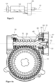
- Figure 4a shows a first embodiment of a bearing arrangement designed according to the invention in a sectional view with a breakout.
- the bearing arrangement is designed as a fixed-loose bearing and comprises a first rotary bearing 19 forming the floating bearing, a second rotary bearing 20 forming the fixed bearing and a pivot ring 21.
- the two rotary bearings 19, 20 are each designed as rolling ball bearings.
- the first pivot bearing 19 is fixed to its outer ring 45 in the direction of the worm shaft rotation axis 13 and is free of fixations on its inner ring in the direction of the worm shaft rotation axis 13, so that the first pivot bearing 19 cannot absorb any forces acting in the direction of the worm shaft rotation axis 13, but rather can only absorb radial forces.
- the first pivot bearing 19 is designed to allow a defined pivoting movement of the worm shaft 12.
- the bearing arrangement serves to support the worm shaft 12, which meshes with the worm wheel 14, in a housing 22 of an electromechanical power steering system.
- the pivot ring 21 is designed to accommodate the second pivot bearing 20 in a form-fitting manner. Specifically, the second pivot bearing 20 is received on its outer ring 45 in the direction of the worm shaft rotation axis 13 by the pivot ring 21, in that a shoulder 46 formed integrally in the outer ring 45 of the second pivot bearing 20 is received in a form-fitting manner by the pivot ring 21.
- the inner ring of the second pivot bearing 20 is fixed in the direction of the worm shaft rotation axis 13 by pressing the inner ring against a shoulder formed in the worm shaft 12 by a securing element 23 that can be screwed onto the end of the worm shaft 12.
- the second pivot bearing 20 can absorb forces and radial forces acting in the direction of the worm shaft rotation axis 13.
- the swivel ring 21 comprises a slotted ring 24 as a first swivel ring component and a sleeve-shaped element 25 as a second swivel ring component, the sleeve-shaped element 25 having a central recess.
- the sleeve-shaped element 25 comprises a disk-shaped section with a central recess and a wall section connected to the disk-shaped section at its radially outer edge and extending in the direction of the worm shaft rotation axis 13.
- the wall section is designed as a raised edge.
- the disk-shaped section and the wall section have approximately the same wall thickness.
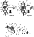
- Figure 4b shows the bearing arrangement Figure 4a in a side view.
- tongues 26 are formed as two second points, the tongues 26 each extending in the direction of the worm shaft rotation axis 13.
- the slotted ring 24 and the sleeve-shaped element 25 are arranged directly adjacent or directly adjacent to one another in the direction of the worm shaft rotation axis 13.
- the pivot ring 21 is designed to act resiliently between the second pivot bearing 20 and the housing 22.
- the sleeve-shaped element 25 of the pivot ring 21 is supported on the axial end facing away from the second pivot bearing 20 Worm shaft 12 on a locking ring 27 designed as a snap ring or bore locking ring in the direction of the worm shaft rotation axis 13.
- the locking ring 27 is embedded or fixed in a form-fitting manner in the opening of the housing 22.
- the pivot ring 21 is designed to form a pivot axis.
- the worm shaft 12 can be pivoted by the bearing arrangement about the pivot axis towards the worm wheel 14.
- the position or spatial position or orientation of the pivot axis depends on the direction of rotation of the worm shaft 12, that is, on the load direction, and on the amount of the load moment.
- the direction of rotation dependence of the position of the pivot axis is implemented as follows.
- the second pivot bearing 20 is pressed against the sleeve-shaped element 25 by the geometry of the meshing teeth of the worm shaft 12 and the worm wheel 14, the sleeve-shaped element 25 being one of its geometrical dimensions Design has corresponding spring action, which in turn causes a reaction moment that presses or pivots the worm shaft 12 in the direction of the worm wheel 14.
- This load case corresponds to load case A Figure 3 .
- the load dependence that is to say the dependence on the amount of the load moment, of the sleeve-shaped element 25 is realized by the elasticity or flexibility of the tongues 26.
- the larger the amount of the load moment the stronger the elastic deformation of the tongues 26 and the greater it is restoring spring force caused by the tongues 26.
- the pivoting of the worm shaft 12 serves to reduce the gear play between the worm shaft 12 and the worm wheel 14.
- the pivot axis runs orthogonally to the radial vector of the worm wheel 14.
- the tongues 26 of the sleeve-shaped element 25 are positioned in such a way that the axis 28 connecting the tongues 26, also referred to as the support point axis or as the second axis, deviates from an axis passing through the worm shaft rotation axis 13, that is, runs off-center, that is, not through the The center of the worm wheel 14 runs through, that is, it does not run through the worm shaft rotation axis 13.
- the tongues 26 are oriented opposite to one another in the circumferential direction.
- the swivel ring 21 is designed such that the swivel axis is formed by sprung support points, which correspond in particular to the two first points of the first swivel ring component and the two second points of the second swivel ring component.
- the position of the pivot axis therefore changes depending on the load.
- the spring-loaded support points are formed by the tongues 26 of the sleeve-shaped element 25.
- the tongues 26 form a point-shaped contact contact between the sleeve-shaped element 25 and the second pivot bearing 20.
- the tongues 26 are elastically deformable and thus have a spring effect in the direction of the worm shaft rotation axis 13.
- the point-shaped support contacts move depending on the forces acting in the direction of the worm shaft rotation axis 13, that is to say on the axial forces.
- Each tongue 26 forms a support point.
- the two tongues 26 thus form the support point axis 28, i.e. in particular the second axis formed by the two second points.
- Figure 4c shows the bearing arrangement Figure 4a in another side view. Compared to the side view Figure 4b
- the locking ring 27 and the sleeve-shaped element 25 are not shown, so that the view of the slotted ring 24, i.e. the first swivel ring component, is clear.
- a first circular arc-shaped, radially inner slot 29 and a second, circular arc-shaped, radially outer slot 30 are formed in the slotted ring 24.
- the first slot 29 and the second slot 30 partially overlap in the circumferential direction, so that a first partial circular ring 31 and a second partial circular ring 32 are created.
- the first partial circular ring 31 and the second partial circular ring 32 are connected by two webs 33.
- the webs 33 are in particular the first two points of the first swivel ring component.
- the two webs 33 each form a material taper between the first partial circular ring 31 and the second partial circular ring 32, so that the first partial circular ring 31 and the second partial circular ring 32 can be pivoted about an axis 34 connecting the two webs 33, also referred to as the taper point axis 34 or as the first axis is.
- the maximum possible stroke for the sleeve-shaped element 25 is determined by the distance to the shoulder 46, for the slotted one Ring 24 through the distance between the support in the housing 22 and the second partial circular ring 32 of the ring 24.
- the load dependence of the slotted ring 24 is realized by the elasticity or flexibility of the webs 33 and thus in particular by the first two points of the first swivel ring component.
- the course or the spatial position or the orientation of the pivot axis is dependent on the respective courses or spatial positions or orientations of the support point axis 28 and the taper point axis 34, and thus in particular on the second axis formed by the two second points of the second pivot ring component and the first axis formed by the two first points of the first pivot ring component.
- the pivot axis of the pivot ring 21 runs parallel to the support point axis 28 and the taper point axis 34 and centrally between the support point axis 28 and the taper point axis 34.
- the pivot axis of the pivot ring 21 also runs parallel to the support point axis 28 and the taper point axis 34. However, the pivot axis then does not run centrally between the second axis 28 and the first axis 34, but rather Depending on the direction of rotation of the worm shaft 12 and on the amount of the load torque to be overcome, closer to the support point axis 28 formed by the two tongues 26, i.e. the second axis 28, or closer to the taper point axis 34 formed by the two webs 33, i.e. the first axis 34.
- the pivot axis runs closer to the support point axis 28, that is, further away from the taper point axis 34 when the tooth forces are directed in the direction of the sleeve-shaped element 25. This corresponds to load case A Figure 3 .
- the pivot axis runs closer to the taper point axis 34, that is, further away from the support point axis 28 when the tooth forces are directed in the direction of the slotted ring 24. This corresponds to load case B Figure 3 .
- Figure 4d shows the bearing arrangement Figure 4a in a view pulled apart along the worm shaft rotation axis 13.
- the sleeve-shaped element 25 includes an anti-twist device 35.
- the anti-twist device 35 ensures that the sleeve-shaped element 25 does not twist relative to the other components over time during operation. This ensures that the pivot axis maintains its intended spatial position.
- the anti-rotation device 35 is designed as a formation extending in the radial direction.
- the anti-rotation device 35 is formed in one piece with the sleeve-shaped element 25. Alternatively, the anti-rotation device 35 can also be designed as a separate component that can be connected to the sleeve-shaped element 25.
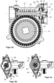
- Figure 5a shows a second embodiment for a bearing arrangement designed according to the invention in a sectional view.
- This second embodiment is fundamentally analogous to the first embodiment Figures 4a-d built up.
- components and components that correspond to the first embodiment are considered to be described accordingly at this point.
- Figure 5b shows the bearing arrangement Figure 5a in a side view.
- the tongues 26, i.e. in particular the two second points, of the sleeve-shaped element 25, i.e. in particular the second swivel ring component, are positioned such that the support point axis 28 connecting the two tongues 26, i.e. in particular the second axis 28 formed by the two second points, is one
- the axis passing through the worm shaft rotation axis 13 is, that is, it runs centrally, that is, it runs through the center of the worm wheel 14, that is, it runs through the worm shaft rotation axis 13.
- Figure 5c shows the bearing arrangement Figure 5a in another side view. Compared to the side view Figure 5b
- the locking ring 27 and the sleeve-shaped element 25 are not shown, so that the view of the slotted ring 24, in particular the first swivel ring component, is clear.
- two webs 33 are formed in the slotted ring 24, i.e. in particular two first points of the first swivel ring component.
- the two webs 33 each form a material taper between the first partial circular ring 31 and the second partial circular ring 32, so that the first Partial circular ring 31 and the second partial circular ring 32 can be pivoted about the taper point axis 34 connecting the webs 33, i.e. in particular about the first axis 34 formed by the two first points.
- the support point axis 28 formed by the two tongues 26, i.e. in particular the second axis 28, runs centrally and that the pivot axis of the swivel ring 21 depends on the support point axis 28, i.e. in particular on the second axis 28, and the taper point axis 34, i.e. in particular the first axis 34, the pivot axis of the pivot ring 21 of the second embodiment runs differently than the pivot axis of the pivot ring 21 of the first embodiment Figures 4a-d .
- Figure 5d shows the bearing arrangement Figure 5a in a view pulled apart along the worm shaft rotation axis 13.
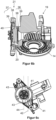
- Figure 6a shows a third embodiment of the bearing arrangement according to the invention in a sectional view with a breakout.
- the worm shaft 13 is not shown.
- the third embodiment of the bearing arrangement according to the invention is fundamentally similar to the first and second embodiments Figures 4a-d or 5a-d constructed. To avoid repetition, components and components that correspond to the first and second embodiments are considered to be described accordingly at this point.
- the swivel ring 21 comprises a first receiving unit 36 with a central recess as the first swivel ring component and a second receiving unit 37 with a central recess as the second swivel ring component.
- the first receiving unit 36 and the second receiving unit 37 each comprise an annular element 38 and a spring unit 39 for the suspension acting in the axial direction, that is to say in the direction of the worm shaft rotation axis 13.
- the spring units 39 each include two separate elastomer cushions. The elastomer cushions in particular form the two first points of the first swivel ring component and the two second points of the second swivel ring component.
- the second pivot bearing 20 is connected to the first receiving unit 36 and the second receiving unit 37 in that the outer ring of the second pivot bearing 20 has a shoulder delimited by an axially central shoulder to the axial stop at both axial ends.
- the two shoulders are designed to accommodate the first receiving unit 36 and the second receiving unit 37.
- the pivot ring 21 further comprises a support element 40 with a central recess, the support element 40 being designed to accommodate the spring unit 39 of the second receiving unit 37.
- Figure 6b shows the bearing arrangement Figure 6a in a sectioned, perspective view with a breakout, the worm shaft 13 not being shown for a better overview.
- Figure 6c shows the bearing arrangement Figure 6a in a side view.
- the annular element 38 of the first receiving unit 36 has formations 41 running in the tangential direction for receiving the associated spring unit 39.
- the formations 41 of the annular element 38 of the first receiving unit 36 form a first formation point axis 42, which corresponds in particular to the first axis 42 formed by the two first points of the first pivot ring component.
- the annular element 38 of the second receiving unit 37 has formations 43 running in the radial direction for receiving the associated spring unit.
- the formations 43 of the annular element 38 of the second receiving unit 37 form a second formation point axis 44, which corresponds in particular to the second axis 44 formed by the two second points of the second pivot ring component.
- the course or the spatial position or the orientation of the pivot axis of the pivot ring 21 is dependent on the respective courses or spatial positions or orientations of the first shaping point axis 42 and the second shaping point axis 44, i.e. in particular on the one through the two first points of the first first axis 42 formed by the swivel ring component and the second axis 44 formed by the two second points of the second swivel ring component.
- the pivot axis runs parallel to and centrally between the first axis 42 and the second axis 44, i.e. in particular the shaping point axes 42, 44.
- the pivot axis of the pivot ring 21 also runs parallel to the first and second shaping point axes 42, 44. However, the pivot axis then does not run centrally between the two axes 42, 44, but depends on the direction of rotation of the worm shaft 12 and the amount of the load torque to be overcome is closer to the second forming point axis 44 formed by the second receiving unit 37 or closer to the first forming point axis 42 formed by the first receiving unit 36. Specifically, the pivot axis runs closer to the second forming point axis 44 , that is, further away from the first molding point axis 42 when the tooth forces are directed in the direction of the second receiving unit 37.
- Figure 6d shows the bearing arrangement Figure 6a in a perspective view without housing.
- Figure 6e shows the bearing arrangement Figure 6a in a view pulled apart along the worm shaft rotation axis 13.
Landscapes
- Engineering & Computer Science (AREA)
- General Engineering & Computer Science (AREA)
- Mechanical Engineering (AREA)
- Chemical & Material Sciences (AREA)
- Combustion & Propulsion (AREA)
- Transportation (AREA)
- Gear Transmission (AREA)
- Power Steering Mechanism (AREA)
Description
- Die vorliegende Erfindung betrifft eine Lageranordnung zur Lagerung einer mit einem Schneckenrad kämmenden Schneckenwelle in einem Gehäuse einer elektromechanischen Servolenkung, umfassend ein erstes Drehlager, ein zweites Drehlager und einen Schwenkring, wobei das erste Drehlager derart ausgebildet ist, eine Verschwenkbewegung der Schneckenwelle zuzulassen, wobei das zweite Drehlager dem Schwenkring angeordnet ist. Weiter betrifft die Erfindung eine elektromechanische Servolenkung mit einem Antriebsmodul, welches einen Antriebsmotor, ein Gehäuse und ein Schneckengetriebe umfasst, wobei eine Schneckenwelle des Schneckengetriebes in einer Lageranordnung gelagert ist.
- In elektromechanischen Servolenkungen wird über einen Elektromotor ein Drehmoment erzeugt, das auf ein Getriebe übertragen und dort dem vom Fahrer gestellten Lenkmoment überlagert wird.
- Solche Lageranordnungen sind aus dem Stand der Technik, beispielsweise aus der
DE 10 2012 103 147 A1 , bereits bekannt. Sie werden beispielsweise in Lenkkraftunterstützungssystemen eingesetzt, wobei sie einen Lenkkraftunterstützungsmotor aufweisen, der eine Schneckenwelle antreibt, die mit einem auf einer Lenkwelle angeordneten Schneckenrad kämmt, wobei das Schneckenrad mit einer Eingangswelle eines Lenkgetriebes in Wirkverbindung steht und wobei die Schneckenwelle und die Lenkwelle in einem gemeinsamen Gehäuse drehbar gelagert sind. Aufgrund der Geometrie der Zähne von Schneckenwelle und Schneckenrad wird die Schneckenwelle im Lastfall von dem Schneckenrad weggedrückt. Dies führt zu unerwünschtem Getriebespiel zwischen Schneckenwelle und Schneckenrad. Zusätzliches Getriebespiel zwischen Schneckenwelle und Schneckenrad wird beispielsweise durch Maßtoleranzen oder Verschleiß der Bauelemente verursacht. Getriebespiel bewirkt unerwünschte Geräusche im Betrieb des Schneckenradgetriebes. Insbesondere beim Lenken mit unmittelbar aufeinanderfolgenden, wechselnden Lenkeinschlagsrichtungen, auch als Wechsellenken bezeichnet, treten diese unerwünschten Geräusche auf. - Eine Lageranordnung eines Lenkgetriebes ist beispielsweise auch aus
DE 10 2017 207 708 A1 bekannt. Die Lageranordnung umfasst einen Schwenkring über dessen Torsionsstege die Lage einer Schwenkachse definierbar ist, indem ein Außenring des Schwenkrings gegenüber dem Innenring des Schwenkrings verschwenkbar ausgestaltet ist. Die Torsionsstege weisen einen radialen Versatz zum Zentrum des Schwenkrings auf, sodass die Schwenkachse in den Radius des Zahneingriffs verlagert wird. Dadurch kann die Ausbildung von Reaktionsmomenten, welche sich aus den Verzahnungskräften im Verzahnungsbereich zwischen Schneckenwelle und Schneckenrad ergeben, reduziert werden. - Als nachteilig erweist sich diese Lösung allerdings dahingehend, dass das Reaktionsmoment im Schwenklager richtungsabhängig ist. Es verstärkt oder schwächt das Abheben der Schnecke in Abhängigkeit davon, welche Betriebslast und Radialkraft auf die Schnecke wirkt. Dadurch entstehen unerwünschte Klappergeräusche. Solche Klappergeräusche werden auch als Rattle Noise bezeichnet.
- In der
DE 10 2009 054 655 A1 ist des Weiteren ein Lenkgetriebe mit einem Schraubritzel beschrieben, das über eine Welle mit einem Anrieb verbunden werden kann. Das Lenkgetriebe umfasst eine Wellenlagerung mit einem ersten Drehlager und einem zweiten Drehlager. Eine Halterung für das erste Drehlager erlaubt dabei aufgrund von vorgesehenen Aussparungen eine Schwenkbewegung für einen ringförmigen Abschnitt der Halterung, was sich geräuschmindernd auf die Wellenlagerung auswirkt. Je nach wirkender Last schwächt sich dabei der positive Effekt dieser Halterung ab. DieDE 10 2008 040 673 A1 offenbart eine ähnliche Wellenlagerung wie dieDE 10 2009 054 655 A1 , welche den Oberbegriff des Anspruchs 1 offenbart. - Eine Getriebeeinheit für ein Kraftfahrzeug mit einer Schneckenwelle, die mit einem Schneckenrad zusammenwirkt, wird auch von der
DE 20 2016 103 794 U1 offenbart. Die Schneckenwelle ist durch ein schwenkbares Drehlager und ein loses Drehlager gelagert. Aus derUS 2018/0058556 A1 ist zudem eine Lageranordnung zur Lagerung einer mit einem Schneckenrad kämmenden Schneckenwelle in einem Gehäuse offenbart, wobei diese Lageranordnung ein erstes Drehlager, ein zweites Drehlager und eine Federscheibe umfasst. Die Federscheibe ist mit Schrauben mit dem Gehäuse verbunden. Die Federscheibe selbst ist nicht dazu bestimmt, den auf die Schneckenwelle wirkenden Axialkräften zu widerstehen. Kippbewegung der Schneckenwelle setzt die Federscheibe geringen Widerstand entgegen. Gegenüber den auf das Hauptlager wirkenden Radialkräften verhält sich die Federscheibe starr. - Eine weitere Lageranordnung für eine Schneckenwelle umfassend ein erstes Drehlager und ein zweites Drehlager offenbart die
DE 10 2016 211 714 B3 . Das zweite Drehlager ist in einem Schwenkring verschwenkbar angeordnet. Axial beiderseits des Schwenkrings sind zwei kreisringartige Federelemente angeordnet. Die Federelemente stützen sich an dem Gehäuse der Lageranordnung und dem Drehlager ab. Durch die Federelemente soll die Steifigkeit des Drehlagers gegenüber Verschiebung in axialer Richtung verstärkt werden, wobei die Steifigkeit gegenüber Schwenkbewegungen im Wesentlichen unbeeinflusst bleiben soll. - Eine Lageranordnung, bei der das Festlager von zwei Lagerschalen umschlossen ist und bei der zwischen Festlager und Lagerschale jeweils ein Federelement angeordnet ist, wird ferner von der
WO 2019/174963 A1 offenbart. - Im Lichte der vorangehend erläuterten Problematik der bekannten Lageranordnungen liegt der vorliegenden Erfindung die Aufgabe zugrunde, eine verbesserte elektromechanische Servolenkung sowie eine verbesserte Lageranordnung zur Lagerung einer mit einem Schneckenrad kämmenden Schneckenwelle in einem Gehäuse einer elektromechanischen Servolenkung zur Verfügung zu stellen, wobei die Lageranordnung insbesondere auch bei sich ändernden Lasten einen gleichbleibend zuverlässigen, geräuscharmen Betrieb ermöglichen soll, und vorteilhafterweise einfach aufgebaut ist.
- Zur Lösung der Aufgabe wird eine Lageranordnung zur Lagerung einer mit einem Schneckenrad kämmenden Schneckenwelle in einem Gehäuse einer elektromechanischen Servolenkung vorgeschlagen. Die Lageranordnung umfasst ein erstes Drehlager, ein zweites Drehlager und einen Schwenkring, wobei das erste Drehlager derart ausgebildet ist, eine Verschwenkbewegung der Schneckenwelle zuzulassen, wobei der Schwenkring eine erste Schwenkringkomponente und eine zweite Schwenkringkomponente umfasst und ausgebildet ist, federnd zwischen dem zweiten Drehlager und dem Gehäuse zu wirken. Das zweite Drehlager ist in dem Schwenkring zumindest teilweise zwischen der ersten Schwenkringkomponente und der zweiten Schwenkringkomponente angeordnet. Erfindungsgemäß weist die erste Schwenkringkomponente zwei erste Punkte auf, bezüglich derer die erste Schwenkringkomponente federnd ausgebildet ist, und die zweite Schwenkringkomponente weist erfindungsgemäß zwei zweite Punkte auf, bezüglich derer die zweite Schwenkringkomponente federnd ausgebildet ist. Die Punkte sind dabei keine Punkte im streng mathematischen Sinne, sondern weisen insbesondere eine gewisse flächige Ausdehnung auf, die jedoch in Bezug auf die jeweilige Schwenkringkomponente um ein Vielfaches kleiner ausgebildet ist. Insbesondere sind die zwei ersten Punkte und die zwei zweiten Punkte jeweils gefederte Auflagepunkte.
- Gemäß einer weiteren vorteilhaften Ausgestaltung ist vorgesehen, dass die ersten zwei Punkte eine erste Achse bilden und die zweiten zwei Punkte eine zweite Achse bilden. Das heißt insbesondere, dass eine Gerade durch die ersten zwei Punkte gelegt wird und eine Gerade durch die zweiten zwei Punkte gelegt wird. Dadurch, dass die Schwenkringkomponenten bezüglich der Punkte federnd ausgebildet sind, lässt sich die jeweilige Schenkringkomponente insbesondere bezüglich der durch das jeweilige Punktepaar gebildeten Achse verschwenken. Vorteilhafterweise sind die erste Achse und die zweite Achse nicht deckungsgleich, die ersten zwei Punkte und die zweiten zwei Punkte sind also insbesondere an unterschiedlichen Stellen angeordnet, sodass die Achsen durch die Punkte verschieden verlaufen. Insbesondere ist vorgesehen, dass die Achsen parallel versetzt zueinander verlaufen.
- In vorteilhafter Weise ist der Schwenkring derart ausgebildet, die Schneckenwelle gegen das Schneckenrad vorzuspannen. Durch die Vorspannung ist ein Abheben der Schneckenwelle von dem Schneckenrad verhindert, sodass das Schneckengetriebe im Wesentlichen spielfrei ist.
- Bevorzugt ist der Schwenkring derart ausgebildet, eine Schwenkachse zum Verschwenken der Schneckenwelle zu bilden. Dadurch kann die Schneckenwelle in Richtung des Schneckenrads gedrückt bzw. verschwenkt werden. Mit anderen Worten ist dadurch ermöglicht, ein Abheben der Schneckenwelle von dem Schneckenrad zu verhindern oder zu reduzieren. Dies verhindert bzw. reduziert das Getriebespiel und verhindert somit unerwünschte Klappergeräusche im Betrieb des Schneckengetriebes. Die Schwenkachse ist insbesondere abhängig von der Ausbildung der zwei ersten Punkte der ersten Schwenkringkomponente und den zwei zweiten Punkten von der zweiten Schwenkringkomponente. Insbesondere ist vorgesehen, dass der Schwenkring derart ausgebildet ist, dass die Schwenkachse durch die zwei ersten Punkte und die zwei zweiten Punkte gebildet ist.
- Weiter bevorzugt ist der Schwenkring derart ausgebildet, dass die Schwenkachse zum Verschwenken der Schneckenwelle orthogonal bzw. normal zum Radialvektor des Schneckenrads verläuft. Eine solche Schwenkbewegung ermöglicht einen vergleichsweise einfachen Aufbau der Lageranordnung.
- Noch weiter bevorzugt ist der Schwenkring derart ausgebildet, dass die Schwenkachse zum Verschwenken der Schneckenwelle durch die gefederten Auflagepunkte gebildet ist. Die Auflagepunkte haben insbesondere einen definierten Abstand zur Drehachse und liegen relativ zueinander, sodass keine Bewegung bzw. kein Schleifen an den Auflagepunkten auftritt.
- In vorteilhafter Weise verändert bzw. verschiebt der Schwenkring über die zwei ersten Punkte und die zwei zweiten Punkte, insbesondere über die gefederten Auflagepunkte, die Position bzw. räumliche Lage der Schwenkachse abhängig von der Drehrichtung der Schneckenwelle. Mit anderen Worten ist der Schwenkring derart ausgebildet, dass die Position bzw. räumliche Lage der Schwenkachse abhängig von der Drehrichtung der Schneckenwelle ist. Die Schwenkachse kann parallel verschoben werden, wodurch sich deren Lage ändert. Die Drehrichtung der Schneckenwelle kann auch als Lastrichtung bezeichnet werden.
- In weiter vorteilhafter Weise verändert bzw. verschiebt der Schwenkring über die zwei ersten Punkte und die zwei zweiten Punkte, insbesondere über die gefederten Auflagepunkte, die Position bzw. räumliche Lage der Schwenkachse abhängig von dem Betrag des zu überwindenden Lastmoments. Mit anderen Worten ist der Schwenkring derart ausgebildet, dass die Position bzw. räumliche Lage der Schwenkachse abhängig von dem Betrag des zu überwindenden Lastmoments ist. Die Schwenkachse kann parallel verschoben werden, wodurch sich deren Lage ändert.
- Gemäß einer weiteren vorteilhaften Ausgestaltung der Lageranordnung weist das zweite Drehlager einen Außenring auf, wobei der Außenring eine Schulter oder einen Absatz ausbildet, an der die erste Schwenkringkomponente und/oder die zweite Schwenkringkomponente angeordnet ist. Der Absatz oder die Schulter sind besonders bevorzugt einstückig am Außenring ausgebildet. Vorteilhafterweise lässt sich hierdurch das Design des Schwenkrings vereinfachen. Insbesondere lässt sich ein Schwenkring, welches ausschließlich die erste Schwenkringkomponente und die zweite Schwenkringkomponente umfasst, und somit zweiteilig ist, realisieren.
- Vorteilhafterweise dient die Schulter beziehungsweise der Absatz des Außenrings für die erste Schwenkringkomponente und/oder die zweite Schwenkringkomponente als mechanischer Anschlag. Vorteilhafterweise wird ein weiterer Anschlag durch ein die Lagerandordnung umgebendes Gehäuse gebildet. Vorteilhafterweise kann dadurch ein zusätzliches Sicherungselement entfallen, welches die erste Schwenkringkomponente und die zweite Schwenkringkomponente in ihrer Anordnungsposition sichert.
- Insbesondere ist vorgesehen, dass das zweite Drehlager einen Außenring aufweist, wobei der Außenring eine Schulter ausbildet, wobei die Schulter von dem Schwenkring formschlüssig aufgenommen ist. Insbesondere lässt sich hierdurch realisieren, dass die erste Schwenkringkomponente einer Seite des zweiten Drehlagers zugeordnet ist und die zweite Schwenkringkomponente der anderen Seites des zweiten Drehlagers zugeordnet ist, ohne dass die Schwenkringkomponenten das Drehlager vollständig umgeben. Vorteilhafterweise lässt sich hierdurch ein flaches Design des Schwenkrings realisieren.
- In einer weiteren vorteilhaften Ausführung der Lageranordnung umfasst der Schwenkring einen geschlitzten Ring, insbesondere einen geschlitzten Ring als die erste Schwenkringkomponente, und ein hülsenförmiges Element, insbesondere ein hülsenförmiges Element als die zweite Schwenkringkomponente. Das hülsenförmige Element weist insbesondere eine zentrale Ausnehmung auf. Das hülsenförmige Element ist insbesondere kreisringförmig und umfasst vorteilhafterweise einen aufgestellten Rand. Der aufgestellte Rand ist insbesondere in Umfangsrichtung durchgängig, das heißt mit geschlossener Zylindermantelfläche. In einer Ausgestaltungsvariante ist der aufgestellte Rand in Umfangsrichtung nicht durchgängig, das heißt der aufgestellte Rand weist eine unterbrochene Zylindermantelfläche auf. Der geschlitzte Ring und das hülsenförmige Element mit zentraler Ausnehmung bilden vorteilhafterweise gemeinsam die Schwenkachse zum Verschwenken der Schneckenwelle. Sowohl der geschlitzte Ring als auch das hülsenförmige Element mit zentraler Ausnehmung haben vorteilhafterweise eine in Axialrichtung wirkende Federung. Die Federung beziehungsweise die Federelemente der Federung sind dabei insbesondere als Elastomerelemente und/oder Federzungen und/oder Biegebalken ausgeführt.
- Bei einem Elastomerelement als Federelement ist insbesondere ein keilförmiges Elastomerelement vorgesehen, welches einen lastabhängigen Auflagepunkt aufweist, und welches vorteilhafterweise so ausgeführt ist, dass auch Radialkräfte übertragen werden können. Die zwei ersten Punkte und/oder die zwei zweiten Punkte einer Schwenkringkomponente bilden dabei vorteilhafterweise jeweils die lastabhängigen Auflagepunkte.
- Bei einem Biegebalken als Federelement ist ebenfalls insbesondere vorgesehen, dass ein solcher Biegebalken einen lastabhängigen Auflagepunkt aufweist. Vorteilhafterweise sind die Biegebalken einer Schwenkachse fest mit dem das Lager fassenden Gehäuse verbunden, um Radialkräfte aufzunehmen. Die Federung mit Biegebalken ist ebenfalls insbesondere durch die zwei ersten Punkte und die zwei zweiten Punkte realisiert, wobei diese Punkte insbesondere die lastabhängigen Auflagepunkte sind.
- Bevorzugterweise ist das Drehlager mit dem geschlitzten Ring und dem hülsenförmigen Element verbunden. Insbesondere kann das Drehlager zwischen dem geschlitzten Ring und dem hülsenförmigen Element, vorzugsweise spielfrei, aufgenommen sein. Beispielsweise kann das Drehlager vermittels seines Außenrings mit dem geschlitzten Ring und dem hülsenförmigen Element verbunden sein. Einerseits kann der Außenring eine Schulter oder einen Absatz aufweisen, wobei die Schulter bzw. der Absatz als mechanischer Anschlag für den geschlitzten Ring und/oder das hülsenförmige Element dient. Auf diese Weise ist das Drehlager in einem "Sandwich-Aufbau" in Axialrichtung zwischen dem geschlitzten Ring und dem hülsenförmigen Element fixiert. Andererseits kann der geschlitzte Ring und/oder das hülsenförmige Element derart ausgebildet sein, den Außenring des Drehlagers gänzlich zu umfassen. Ein zusätzliches Befestigungsmittel zur Schaffung des Schwenkrings erübrigt sich dadurch. So vereinfacht sich der Aufbau des Schwenkrings und somit der Aufbau der Lageranordnung.
- Weiter bevorzugterweise sind in dem geschlitzten Ring ein erster kreisbogenförmiger, radial innerer Schlitz und ein zweiter, kreisbogenförmiger, radial äußerer Schlitz ausgebildet, wobei der erste Schlitz und der zweite Schlitz sich in Umfangsrichtung teilweise überlagern, sodass ein erster, radial innerer Kreisring, insbesondere ein Teilkreisring, und ein zweiter, radial äußerer Kreisring, insbesondere ein Teilkreisring, entstehen, wobei der erste Kreisring und der zweite Kreisring durch zwei Stege verbunden sind. Die Stege sind dabei insbesondere die zwei ersten Punkte der ersten Schwenkringkomponente. Die Stege können insbesondere als Materialverjüngung ausgebildet sein. Die Stege dienen vorteilhafterweise zur Federung des geschlitzten Rings in Axialrichtung des Schwenkrings und nehmen dadurch die auftretenden Radialkräfte auf. Die Stege spannen insbesondere Teilkreise auf, die durch die Schlitze gebildet sind. In der Lastrichtung, bei der das zweite Drehlager gegen den geschlitzten Ring gedrückt wird, bilden bzw. definieren hauptsächlich die zwei Stege des geschlitzten Rings die Schwenkachse. In einem solchen Lastfall entspricht die Schwenkachse im Wesentlichen der durch die zwei Stege, und somit insbesondere der durch die zwei ersten Punkte, verlaufenden Achse.
- Noch weiter bevorzugterweise umfasst das hülsenförmige Element einen scheibenförmigen Abschnitt mit zentraler Ausnehmung. Vorteilhafterweise umfasst das hülsenförmige Element weiter einen mit dem scheibenförmigen Abschnitt an dessen radial äußerem Rand verbundenen, sich in Axialrichtung der Schneckenwelle erstreckenden Wandungsabschnitt. Insbesondere ist vorgesehen, dass in dem scheibenförmigen Abschnitt Zungen, insbesondere als die zwei zweiten Punkte der zweiten Schwenkringkomponente, ausgebildet sind, wobei die Zungen sich jeweils in Axialrichtung der Schneckenwelle erstrecken. Die Zungen dienen vorteilhafterweise zur Federung des hülsenförmigen Elements in Axialrichtung des Schwenkrings. In der Lastrichtung, bei der das zweite Drehlager gegen das hülsenförmige Element gedrückt wird, bilden bzw. definieren hauptsächlich die zwei Zungen, also insbesondere die zwei zweiten Punkte, des hülsenförmigen Elements die Schwenkachse. In einem solchen Lastfall entspricht die Schwenkachse im Wesentlichen der durch die zwei Zungen, und somit insbesondere der durch die zwei zweiten Punkte, verlaufenden Achse.
- Die Zungen können derart positioniert sein, dass die die Zungen verbindende Achse, also insbesondere die zweite Achse, von einer durch die Längsachse der Schneckenwelle hindurchführenden Achse abweichend ist. Insbesondere sind die Zungen derart positioniert, dass die die Zungen verbindende Achse nicht eine durch die Längsachse der Schneckenwelle hindurchführende Achse ist. Insbesondere schneiden sich die Längsachse der Schneckenwelle und die die Zungen verbindende Achse bei dieser Ausgestaltung nicht und sind somit insbesondere voneinander beabstandet. Die die Zungen verbindende Achse verläuft bei dieser Ausgestaltung vorteilhafterweise nicht durch den Mittelpunkt des hülsenförmigen Elements. Insbesondere können die Längsachse der Schneckenwelle und die die Zungen verbindende Achse orthogonal zueinander sein. Vorteilhafterweise führt bei dieser Ausgestaltungsvariante die die Stege des geschlitzten Rings verbindende Achse, also insbesondere die erste Achse, durch die Längsachse der Schneckenwelle. Die Zungen spannen vorteilhafterweise einen Teilkreis auf.
- Alternativ können die Zungen derart positioniert sein, dass die die Zungen verbindende Achse eine durch die Längsachse der Schneckenwelle hindurchführende Achse ist. Bei diesem Ausführungsbeispiel schneiden sich vorteilhafterweise die Längsachse der Schneckenwelle und die die Zungen verbindende Achse. Insbesondere können auch bei dieser Ausgestaltungsalternative die Längsachse der Schneckenwelle und die die Zungen verbindende Achse orthogonal zueinander sein. Bei dieser Ausgestaltungsalternative ist insbesondere vorgesehen, dass die die Stege des geschlitzten Rings verbindende Achse, also insbesondere die erste Achse, nicht eine durch die Längsachse der Schneckenwelle hindurchführende Achse ist. Insbesondere schneiden sich die Längsachse der Schneckenwelle und die Stege des geschlitzten Rings verbindende Achse bei dieser Ausgestaltung nicht und sind somit insbesondere voneinander beabstandet.
- In vorteilhafter Weise können die Zungen einander in Umfangsrichtung entgegengesetzt orientiert sein. Mit anderen Worten können die Zungen in Bezug auf eine gedachte, durch den Mittelpunkt des Schwenkrings verlaufende Symmetrieachse gegenüberliegend angeordnet sein.
- In einer weiteren Ausführung der Lageranordnung umfasst der Schwenkring eine erste Aufnahmeeinheit mit zentraler Ausnehmung und eine zweite Aufnahmeeinheit mit zentraler Ausnehmung, wobei die erste Aufnahmeeinheit und die zweite Aufnahmeeinheit jeweils ein ringförmiges Element und eine Federeinheit zur in Axialrichtung wirkenden Federung umfassen. Die erste Aufnahmeeinheit ist dabei vorteilhafterweise die erste Schwenkringkomponente und die zweite Aufnahmeeinheit ist vorteilhafterweise die zweite Schwenkringkomponente. Die zwei ersten Punkte der ersten Schwenkringkomponente und die zwei zweiten Punkte der zweiten Schwenkringkomponente werden vorteilhafterweise durch die jeweilige Federeinheit gebildet.
- Bevorzugterweise ist das zweite Drehlager mit dem ersten Aufnahmeelement und dem zweiten Aufnahmeelement verbunden. Insbesondere kann das Drehlager zwischen dem ersten Aufnahmeelement und dem zweiten Aufnahmeelement, vorzugsweise spielfrei, aufgenommen sein. Beispielsweise kann das Drehlager vermittels seines Außenrings mit dem ersten Aufnahmeelement und dem zweiten Aufnahmeelement verbunden sein.
- Es ist weiterhin bevorzugt, dass der Schwenkring ein Stützelement mit zentraler Ausnehmung umfasst, wobei das Stützelement derart ausgebildet ist, die Federeinheit, insbesondere die Federeinheit einer der Aufnahmeeinheiten, aufzunehmen.
- Das ringförmige Element der ersten Aufnahmeeinheit kann vorteilhafterweise in Tangentialrichtung verlaufende Anformungen zur Aufnahme der zugehörigen Federeinheit aufweisen. Die Anformungen sind insbesondere einstückig mit der ersten Aufnahmeeinheit ausgebildet.
- Weiterhin kann das ringförmige Element der zweiten Aufnahmeeinheit vorteilhafterweise in Radialrichtung verlaufende Anformungen zur Aufnahme der zugehörigen Federeinheit aufweisen. Die Anformungen sind insbesondere einstückig mit der zweiten Aufnahmeeinheit ausgebildet.
- Die Federeinheit kann in einer besonderen Ausführung ein oder mehrere Elastomerkissen umfassen.
- Die erste Schwenkringkomponente und/oder die zweite Schwenkringkomponente, insbesondere das hülsenförmige Element und/oder das erste Aufnahmeelement und/oder das zweite Aufnahmeelement und/oder das Stützelement, können bzw. kann gemäß einer weiteren vorteilhaften Ausgestaltung eine Verdrehsicherung aufweisen. Die Verdrehsicherung stellt vorteilhafterweise sicher, dass die räumliche Lage der Schwenkachse unveränderlich bleibt. Dadurch bleibt auch, insbesondere bei möglicherweise entstehenden Vibrationen, während des bestimmungsgemäßen Betriebs die Schwenkachse konstant. Ein sicherer Betrieb ist somit gewährleistet.
- Zur Lösung der eingangs genannten Aufgabe wird zudem eine elektromechanische Servolenkung mit einem Antriebsmodul vorgeschlagen, welches einen Antriebsmotor, ein Gehäuse, ein Schneckengetriebe und eine Lageranordnung umfasst. Das Schneckengetriebe umfasst dabei eine Schneckenwelle mit einer Schneckenwellendrehachse und ein Schneckenrad mit einer Schneckenraddrehachse. Insbesondere ist vorgesehen, dass die Schneckenwelle von dem Antriebsmotor angetrieben wird. Die Schneckenwelle ist dabei in der Lageranordnung gelagert, wobei die Lageranordnung gemäß einer erfindungsgemäßen Ausgestaltung ausgebildet ist. Insbesondere ist vorgesehen, dass die elektromechanische Servolenkung ein Steer-by-Wire-Lenksystem ist.
- Weiter vorteilhafte Einzelheiten, Merkmale und Ausgestaltungsdetails der Erfindung werden im Zusammenhang mit den in den Figuren dargestellten Ausführungsbeispielen näher erläutert.
- Vorteilhafte Ausführungsformen der Erfindung sind im Folgenden anhand der Zeichnung näher erläutert. Darin zeigen im Einzelnen
- Figur 1
- ein Ausführungsbeispiel für eine erfindungsgemäß ausgebildete elektromechanische Servolenkung in einer schematischen, perspektivischen Darstellung,
- Figur 2
- ein Antriebsmodul für eine erfindungsgemäß ausgebildete elektromechanische Servolenkung in einer schematischen, perspektivischen Darstellung,
- Figur 3
- ein abstraktes Ausführungsbeispiel für eine erfindungsgemäß ausgebildete Lageranordnung in einem stark vereinfachten Schaubild,
- Figur 4a-d
- zeigt eine erste Ausführungsform für eine erfindungsgemäß ausgebildete Lageranordnung in verschiedenen Darstellungen,
- Figur 5a-d
- zeigt eine zweite Ausführungsform für eine erfindungsgemäß ausgebildete Lageranordnung in verschiedenen Darstellungen und
- Figur 6a-e
- zeigt eine dritte Ausführungsform für eine erfindungsgemäß ausgebildete Lageranordnung in verschiedenen Darstellungen.
- In den verschiedenen Figuren sind gleiche Teile stets mit den gleichen Bezugszeichen versehen und sind daher in der Regel jeweils nur einmal benannt bzw. erwähnt.
-
Figur 1 zeigt eine elektromechanische Servolenkung in einer schematischen, perspektivischen Darstellung. - Die elektromechanische Servolenkung umfasst eine Lenksäule 1 und ein Lenkgetriebe 2. Die Lenksäule 1 umfasst eine Lenkspindel 3, an deren dem Fahrer zugewandten Ende ein Lenkrad 4 befestigt ist. Das Lenkrad 4 kann auch als Lenkhandhabe bezeichnet werden. Das Lenkgetriebe 2 umfasst ein Lenkritzel 5, eine Lenkzahnstange 6 und zwei Lenkspurstangen 7. Das Lenkritzel 5 und die Lenkzahnstange 6 stehen im Eingriff miteinander. Das Lenkgetriebe 2 dient der Übersetzung von Lenkbefehlen, die durch Drehungen des Lenkrads 4 erzeugbar sind, in entsprechende Drehungen von gelenkten Fahrzeugrädern 8.
- Das Lenkritzel 5 ist in bekannter Weise durch eine kinematische Verbindung mit der Lenkzahnstange 6, der jeweiligen Lenkspurstange 7 und dem jeweiligen gelenkten Fahrzeugrad 8 mechanisch gekoppelt. Somit kann der Lenkbefehl von dem Lenkrad 4 hin zu den jeweiligen gelenkten Fahrzeugrädern 8 übertragen werden, nämlich von der Lenkspindel 3 hin zu dem Lenkgetriebe 2 durch mechanische Kopplung und innerhalb des Lenkgetriebes 2 ebenfalls durch mechanische Kopplung. Das Lenkritzel 5 wird dabei zur Lenkunterstützung von dem Antriebsmodul 11 angetrieben.
- Die elektromechanische Servolenkung kann alternativ als ein in den Figuren nicht dargestelltes Steer-by-Wire Lenksystem ausgebildet sein, sodass der Lenkbefehl von dem Lenkrad 4 hin zu den jeweiligen gelenkten Fahrzeugrädern 8 übertragen wird, nämlich von der Lenkspindel 3 hin zu dem Lenkgetriebe 2 durch elektrische Kopplung und innerhalb des Lenkgetriebes 2 durch mechanische Kopplung. Die elektrische Kopplung kann in Form einer Datenübertragungseinrichtung, beispielsweise einem Datenkabel, ausgebildet sein.
- Zur Lenkkraftunterstützung sind in der elektromechanischen Servolenkung in diesem Ausführungsbeispiel ein Antriebsmodul 9 und das Antriebsmodul 11 gezeigt. Das Antriebsmodul 9 und das Antriebsmodul 11 umfassen dabei jeweils - in
Figur 1 nicht explizit dargestellt - einen Antriebsmotor, ein Gehäuse, ein Schneckengetriebe mit einer Schneckenwelle und einem Schneckenrad, wobei die Schneckenwelle in einer Lageranordnung gelagert ist. - Allgemein kann bei einer elektromechanischen Servolenkung ein Antriebsmodul an der Lenksäule 1 angebracht sein oder einen am Lenkritzel 5 mit der Lenkwelle 10 gekoppelten Hilfskraftantrieb 31 aufweisen. Die Antriebsmodule 9,11 können dabei gleichartig aufgebaut sein. Durch das Antriebsmodul 9,11 kann ein Hilfsdrehmoment in die Lenkspindel 3 und/oder das Lenkritzel 5 eingekoppelt werden, um den Fahrer bei der Lenkarbeit zu unterstützten.
- Insbesondere ist aber vorgesehen, dass die elektromechanische Servolenkung nur ein Antriebsmodul 9 oder ein Antriebsmodul 11 aufweist, insbesondere an einer der in
Figur 1 gezeigten Positionen. - Ein Ausführungsbeispiel für ein Antriebsmodul 9 wird dabei unter Bezugnahme auf
Figur 2 näher erläutert. Die Lageranordnung des Antriebsmoduls 9 kann insbesondere, wie unter Bezugnahme auf die Ausführungsbeispiele gemäßFigur 3 bis Figur 6e erläutert, ausgebildet sein. Das Antriebsmodul 11 kann entsprechend aufgebaut sein. -
Figur 2 zeigt ein Ausführungsbeispiel für ein Antriebsmodul 9,11 für eine elektromechanische Servolenkung in einer schematischen, perspektivischen Darstellung, umfassend ein Schneckengetriebe 10 und einen Antriebsmotor 11. - Das Schneckengetriebe 10 umfasst eine in
Figur 2 nicht dargestellte Schneckenwelle 12 mit einer Schneckenwellendrehachse 13 und ein Schneckenrad 14 mit einer Schneckenraddrehachse 15. Die Schneckenwellendrehachse 13 ist die Längsachse der Schneckenwelle 12. Die Schneckenwelle 12, auch als Schnecke bezeichnet, ist durch ein Gehäuseelement 16 und einen Gehäusedeckel 17 des Schneckengetriebes 10 zum Schutz vor Schmutz und Fremdkörpern umgeben. Die Schneckenwelle 12 wird von einer inFigur 2 nicht dargestellten Lageranordnung gelagert, wobei die Lageranordnung insbesondere, wie unter Bezugnahme aufFigur 4a bis Figur 6e erläutert, ausgebildet sein kann. - Der Antriebsmotor 11 treibt die Schneckenwelle 12 an, die drehbar um die Schneckenwellendrehachse 13 gelagert ist. Die Schneckenwelle 12 steht mit dem Schneckenrad 14 im Eingriff. Wenn sich die Schneckenwelle 12 dreht, dreht sich daher das Schneckenrad 14 um die Schneckenraddrehachse 15. Eine Abtriebswelle 18 ist drehfest mit dem Schneckenrad 14 verbunden und dreht gemeinsam mit dem Schneckenrad 14 um die Schneckenraddrehachse 15.
-
Figur 3 zeigt ein Ausführungsbeispiel für eine Lageranordnung in einem stark vereinfachten Schaubild. - Die Lageranordnung umfasst die Schneckenwelle 12, die drehbar um die Schneckenwellendrehachse 13 gelagert ist. Die Schneckenwelle 12 ist an ihrem ersten, axialen Ende durch ein erstes Drehlager 19 gelagert und an ihrem zweiten, axialen Ende durch ein zweites Drehlager 20 gelagert. Das erste Drehlager 19 ist derart ausgebildet, eine definierte Verschwenkbewegung der Schneckenwelle 12 zuzulassen. Das zweite Drehlager 20 ist als Schwenkdrehlager ausgebildet, indem das zweite Drehlager 20 innerhalb eines in
Figur 3 nicht dargestellten Schwenkrings angeordnet ist. - Der besseren Übersicht halber sind zwei gesonderte Lastfälle gemeinsam in
Figur 3 dargestellt, nämlich Lastfall A und Lastfall B. Die Lastfälle unterscheiden sich voneinander durch einander entgegengesetzte Drehrichtungen der Schneckenwelle 12. - Im Lastfall A wirkt eine Zahnkraft FA,1 im Punkt des Eingriffs zwischen der Schneckenwelle 12 und des in
Figur 3 nicht dargestellten Schneckenrads 14 in Richtung des zweiten Drehlagers 20. Die Zahnkraft FA,1 bewirkt eine Lagerreaktionskraft FA,2. Daraus ergibt sich ein Reaktionsmoment, das die Schneckenwelle 12 in Richtung des Schneckenrads 14 drückt bzw. verschwenkt. - Im Lastfall B wirkt eine Zahnkraft FB,1 im Punkt des Eingriffs zwischen der Schneckenwelle 12 und des Schneckenrads 14 in Richtung des ersten Drehlagers 19. Die Zahnkraft FB,1 bewirkt eine Lagerreaktionskraft FB,2. Daraus ergibt sich ebenfalls ein Reaktionsmoment, das die Schneckenwelle 12 in Richtung des Schneckenrads 14 drückt bzw. verschwenkt.
-
Figur 4a zeigt eine erste Ausführungsform einer erfindungsgemäß ausgebildeten Lageranordnung in einer Schnittdarstellung mit Ausbruch. - Die Lageranordnung ist als eine Fest-Los-Lagerung ausgestaltet und umfasst ein erstes, das Loslager bildende Drehlager 19, ein zweites, das Festlager bildende Drehlager 20 und einen Schwenkring 21. Die beiden Drehlager 19, 20 sind jeweils als Wälzkugellager ausgebildet. Das erste Drehlager 19 ist an dessen Außenring 45 in Richtung der Schneckenwellendrehachse 13 fixiert und an dessen Innenring in Richtung der Schneckenwellendrehachse 13 frei von Fixierungen, sodass das erste Drehlager 19 keine in Richtung der Schneckenwellendrehachse 13 wirkenden Kräfte aufnehmen kann, sondern ausschließlich Radialkräfte aufnehmen kann. Das erste Drehlager 19 ist derart ausgebildet, eine definierte Verschwenkbewegung der Schneckenwelle 12 zuzulassen.
- Die Lageranordnung dient zur Lagerung der mit dem Schneckenrad 14 kämmenden Schneckenwelle 12 in einem Gehäuse 22 einer elektromechanischen Servolenkung. Der Schwenkring 21 ist derart ausgebildet, das zweite Drehlager 20 formschlüssig aufzunehmen. Im Konkreten ist das zweite Drehlager 20 an dessen Außenring 45 in Richtung der Schneckenwellendrehachse 13 durch den Schwenkring 21 aufgenommen, indem eine in dem Außenring 45 des zweiten Drehlagers 20 einstückig ausgebildete Schulter 46 von dem Schwenkring 21 formschlüssig aufgenommen ist. Der Innenring des zweiten Drehlagers 20 ist in Richtung der Schneckenwellendrehachse 13 fixiert, indem der Innenring durch ein auf das Ende der Schneckenwelle 12 aufschraubbares Sicherungselement 23 gegen eine in der Schneckenwelle 12 ausgebildete Schulter gepresst ist. Das zweite Drehlager 20 kann in Richtung der Schneckenwellendrehachse 13 wirkende Kräfte und Radialkräfte aufnehmen.
- Der Schwenkring 21 umfasst als eine erste Schwenkringkomponente einen geschlitzten Ring 24 und als eine zweite Schwenkringkomponente ein hülsenförmiges Element 25, wobei das hülsenförmige Element 25 eine zentrale Ausnehmung aufweist.
- Das hülsenförmige Element 25 umfasst einen scheibenförmigen Abschnitt mit zentraler Ausnehmung und einen mit dem scheibenförmigen Abschnitt an dessen radial äußeren Rand verbundenen, sich in Richtung der Schneckenwellendrehachse 13 erstreckenden Wandungsabschnitt. Der Wandungsabschnitt ist als aufgestellter Rand ausgebildet. Der scheibenförmige Abschnitt und der Wandungsabschnitt weisen in etwa dieselbe Wandungsdicke auf.
-
Figur 4b zeigt die Lageranordnung ausFigur 4a in einer Seitenansicht. - In dem scheibenförmigen Abschnitt des hülsenförmigen Elements 25 sind Zungen 26 als zwei zweite Punkte ausgebildet, wobei die Zungen 26 sich jeweils in Richtung der Schneckenwellendrehachse 13 erstrecken. Der geschlitzte Ring 24 und das hülsenförmige Element 25 sind in Richtung der Schneckenwellendrehachse 13 zueinander unmittelbar angrenzend bzw. direkt anliegend angeordnet.
- Der Schwenkring 21 ist derart ausgebildet, federnd zwischen dem zweiten Drehlager 20 und dem Gehäuse 22 zu wirken. Zu diesem Zweck stützt sich das hülsenförmige Element 25 des Schwenkrings 21 auf dem dem zweiten Drehlager 20 abgewandten axialen Ende der Schneckenwelle 12 an einem als Sprengring bzw. Bohrungssicherungsring ausgebildeten Sicherungsring 27 in Richtung der Schneckenwellendrehachse 13 ab. Der Sicherungsring 27 ist formschlüssig in der Öffnung des Gehäuses 22 eingelassen bzw. fixiert.
- Der Schwenkring 21 ist derart ausgebildet, eine Schwenkachse zu bilden. Die Schneckenwelle 12 ist durch die Lageranordnung um die Schwenkachse hin zu dem Schneckenrad 14 verschwenkbar. Die Position bzw. räumliche Lage bzw. Orientierung der Schwenkachse ist abhängig von der Drehrichtung der Schneckenwelle 12, das heißt von der Lastrichtung, und von dem Betrag des Lastmoments. Die Drehrichtungsabhängigkeit der Position der Schwenkachse ist folgendermaßen verwirklicht.
- In dem einen Lastfall, das heißt während der einen Drehrichtung der Schneckenwelle 12, wird durch die Geometrie der im Eingriff befindlichen Zähne der Schneckenwelle 12 und des Schneckenrads 14 das zweite Drehlager 20 gegen das hülsenförmige Element 25 gedrückt, wobei das hülsenförmige Element 25 eine dessen geometrischer Ausgestaltung entsprechende Federwirkung aufweist, die wiederum ein Reaktionsmoment bewirkt, das die Schneckenwelle 12 in Richtung des Schneckenrads 14 drückt bzw. verschwenkt. Dieser Lastfall entspricht Lastfall A gemäß
Figur 3 . - In dem anderen Lastfall, das heißt während der anderen Drehrichtung der Schneckenwelle 12, wird durch die Geometrie der im Eingriff befindlichen Zähne der Schneckenwelle 12 und des Schneckenrads 14 das zweite Drehlager 20 in Axialrichtung der Schneckenwelle 12 gegen den geschlitzten Ring 24 gedrückt, wobei der geschlitzte Ring 24 eine dessen geometrischer Ausgestaltung entsprechende Federwirkung aufweist, die wiederum ein Reaktionsmoment bewirkt, das die Schneckenwelle 12 in Richtung des Schneckenrads 14 drückt bzw. verschwenkt. Dieser Lastfall entspricht Lastfall B gemäß
Figur 3 . - Die Lastabhängigkeit, das heißt die Abhängigkeit von dem Betrag des Lastmoments, des hülsenförmigen Elements 25 ist verwirklicht durch die Elastizität bzw. Nachgiebigkeit der Zungen 26. Je größer der Betrag des Lastmoments ist desto stärker ist die elastische Verformung der Zungen 26 und desto größer ist die durch die Zungen 26 bewirkte rückstellende Federkraft.
- Die Verschwenkung der Schneckenwelle 12 dient dazu, das Getriebespiel zwischen der Schneckenwelle 12 und dem Schneckenrad 14 zu verringern. Die Schwenkachse verläuft orthogonal zum Radialvektor des Schneckenrads 14.
- Die Zungen 26 des hülsenförmigen Elements 25 sind derart positioniert, dass die die Zungen 26 verbindende Achse 28, auch als Auflagepunktachse oder als zweite Achse bezeichnet, von einer durch die Schneckenwellendrehachse 13 hindurchführenden Achse abweichend ist, das heißt außermittig verläuft, das heißt nicht durch den Mittelpunkt des Schneckenrads 14 hindurch verläuft, das heißt nicht durch die Schneckenwellendrehachse 13 hindurch verläuft. Die Zungen 26 sind einander in Umfangsrichtung entgegengesetzt orientiert.
- Der Schwenkring 21 ist derart ausgebildet, dass die Schwenkachse durch gefederte Auflagepunkte, die insbesondere den zwei ersten Punkten der ersten Schwenkringkomponente und den zwei zweiten Punkten der zweiten Schwenkringkomponente entsprechen, gebildet ist. Die Lage der Schwenkachse ändert sich dadurch lastabhängig. Die gefederten Auflagepunkte sind durch die Zungen 26 des hülsenförmigen Elements 25 gebildet. Die Zungen 26 bilden einen punktförmigen Auflagekontakt zwischen dem hülsenförmigen Element 25 und dem zweiten Drehlager 20. Die Zungen 26 sind elastisch verformbar und weisen somit eine Federwirkung in Richtung der Schneckenwellendrehachse 13 auf. Die punktförmigen Auflagekontakte verschieben sich in Abhängigkeit von der in Richtung der Schneckenwellendrehachse 13 wirkenden Kräfte, das heißt von den Axialkräften. Jede Zunge 26 bildet einen Auflagepunkt. Somit bilden die zwei Zungen 26 die Auflagepunktachse 28, also insbesondere die von den zwei zweiten Punkten gebildete zweite Achse.
-
Figur 4c zeigt die Lageranordnung ausFigur 4a in einer weiteren Seitenansicht. Im Vergleich zur Seitenansicht gemäßFigur 4b sind der besseren Übersicht halber der Sicherungsring 27 und das hülsenförmige Element 25 nicht dargestellt, sodass die Sicht auf den geschlitzten Ring 24, also die erste Schwenkringkomponente, frei ist. - In dem geschlitzten Ring 24 sind ein erster kreisbogenförmiger, radial innerer Schlitz 29 und ein zweiter, kreisbogenförmiger, radial äußerer Schlitz 30 ausgebildet. Der erste Schlitz 29 und der zweite Schlitz 30 überlagern sich in Umfangsrichtung teilweise, sodass ein erster Teilkreisring 31 und ein zweiter Teilkreisring 32 entstehen. Der erste Teilkreisring 31 und der zweite Teilkreisring 32 sind durch zwei Stege 33 verbunden. Die Stege 33 sind dabei insbesondere die zwei ersten Punkte der ersten Schwenkringkomponente. Die zwei Stege 33 bilden jeweils eine Materialverjüngung zwischen dem ersten Teilkreisring 31 und dem zweiten Teilkreisring 32, sodass der erste Teilkreisring 31 und der zweite Teilkreisring 32 um eine die beiden Stege 33 verbindende Achse 34, auch als Verjüngungspunktachse 34 oder als erste Achse bezeichnet, verschwenkbar ist. Der maximal mögliche Hub wird für das hülsenförmige Element 25 durch den Abstand zur Schulter 46 bestimmt, für den geschlitzten Ring 24 durch den Abstand zwischen der Auflage im Gehäuse 22 und dem zweiten Teilkreisring 32 des Ringes 24.
- Die Lastabhängigkeit des geschlitzten Rings 24 ist verwirklicht durch die Elastizität bzw. Nachgiebigkeit der Stege 33 und somit insbesondere durch die zwei ersten Punkte der ersten Schwenkringkomponente. Je größer der Betrag des Lastmoments ist desto stärker ist die elastische Verformung der Stege 33 und desto größer ist die durch die Stege 33 bewirkte rückstellende Federkraft.
- Der Verlauf bzw. die räumliche Lage bzw. die Orientierung der Schwenkachse ist abhängig von den jeweiligen Verläufen bzw. räumlichen Lagen bzw. Orientierungen der Auflagepunktachse 28 und der Verjüngungspunktachse 34, und somit insbesondere von der durch die zwei zweiten Punkte der zweiten Schwenkringkomponente gebildeten zweiten Achse und der durch die zwei ersten Punkte der ersten Schwenkringkomponente gebildeten ersten Achse.
- Im Fall ohne Last, das heißt wenn die Schneckenwelle 12 sich nicht dreht, verläuft die Schwenkachse des Schwenkrings 21 parallel zu der Auflagepunktachse 28 und der Verjüngungspunktachse 34 sowie mittig zwischen der Auflagepunktachse 28 und der Verjüngungspunktachse 34.
- Im Fall mit Last, das heißt wenn die Schneckenwelle 12 sich dreht, verläuft die Schwenkachse des Schwenkrings 21 ebenfalls parallel zu der Auflagepunktachse 28 und der Verjüngungspunktachse 34. Allerdings verläuft die Schwenkachse dann nicht mittig zwischen der zweiten Achse 28 und der ersten Achse 34, sondern abhängig von der Drehrichtung der Schneckenwelle 12 und von dem Betrag des zu überwindenden Lastmoments näher zu der durch die beiden Zungen 26 gebildeten Auflagepunktachse 28, also der zweiten Achse 28, oder näher zu der durch die beiden Stege 33 gebildeten Verjüngungspunktachse 34, also der ersten Achse 34. Im Konkreten verläuft die Schwenkachse näher zu der Auflagepunktachse 28, das heißt entfernter von der Verjüngungspunktachse 34, wenn die Zahnkräfte in Richtung des hülsenförmigen Elements 25 gerichtet sind. Dies entspricht Lastfall A gemäß
Figur 3 . Demgegenüber verläuft die Schwenkachse näher zu der Verjüngungspunktachse 34, das heißt entfernter von der Auflagepunktachse 28, wenn die Zahnkräfte in Richtung geschlitzter Ring 24 gerichtet sind. Dies entspricht Lastfall B gemäßFigur 3 . -
Figur 4d zeigt die Lageranordnung ausFigur 4a in einer entlang der Schneckenwellendrehachse 13 auseinandergezogenen Darstellung. - Das hülsenförmige Element 25 umfasst eine Verdrehsicherung 35. Die Verdrehsicherung 35 gewährleistet, dass sich das hülsenförmige Element 25 im Laufe der Zeit während des Betriebs nicht relativ zu den anderen Bauelementen verdreht. Dies stellt sicher, dass die Schwenkachse ihre vorgesehene räumliche Lage beibehält. Die Verdrehsicherung 35 ist als eine sich in Radialrichtung erstreckende Anformung ausgebildet. Die Verdrehsicherung 35 ist einstückig mit dem hülsenförmigen Element 25 ausgebildet. Alternativ kann die Verdrehsicherung 35 auch als gesondertes Bauteil ausgebildet sein, das mit dem hülsenförmigen Element 25 verbindbar ist.
-
Figur 5a zeigt eine zweite Ausführungsform für eine erfindungsgemäß ausgebildete Lageranordnung in einer Schnittdarstellung. Diese zweite Ausführungsform ist grundsätzlich analog zu der ersten Ausführungsform gemäßFiguren 4a-d aufgebaut. Zur Vermeidung von Wiederholungen gelten daher an dieser Stelle mit der ersten Ausführungsform übereinstimmende Bestandteile und Bauelemente als entsprechend beschrieben. -
Figur 5b zeigt die Lageranordnung ausFigur 5a in einer Seitenansicht. - Die Zungen 26, also insbesondere die zwei zweiten Punkte, des hülsenförmigen Elements 25, also insbesondere der zweiten Schwenkringkomponente, sind derart positioniert, dass die die beiden Zungen 26 verbindende Auflagepunktachse 28, also insbesondere die durch die zwei zweiten Punkte gebildete zweite Achse 28, eine durch die Schneckenwellendrehachse 13 hindurchführenden Achse ist, das heißt mittig verläuft, das heißt durch den Mittelpunkt des Schneckenrads 14 hindurch verläuft, das heißt durch die Schneckenwellendrehachse 13 hindurch verläuft.
-
Figur 5c zeigt die Lageranordnung ausFigur 5a in einer weiteren Seitenansicht. Im Vergleich zur Seitenansicht gemäßFigur 5b sind der besseren Übersicht halber der Sicherungsring 27 und das hülsenförmige Element 25 nicht dargestellt, sodass die Sicht auf den geschlitzten Ring 24, also insbesondere die erste Schwenkringkomponente, frei ist. - In dem geschlitzten Ring 24 sind, analog zu dem geschlitzten Ring der ersten Ausführungsform, zwei Stege 33 ausgebildet, also insbesondere zwei erste Punkte der ersten Schwenkringkomponente. Die zwei Stege 33 bilden jeweils eine Materialverjüngung zwischen dem ersten Teilkreisring 31 und dem zweiten Teilkreisring 32, sodass der erste Teilkreisring 31 und der zweite Teilkreisring 32 um die die Stege 33 verbindende Verjüngungspunktachse 34, also insbesondere um die von den zwei ersten Punkten gebildete erste Achse 34, verschwenkbar ist.
- Dadurch, dass die durch die beiden Zungen 26 gebildete Auflagepunktachse 28, also insbesondere die zweite Achse 28, mittig verläuft und dass die Schwenkachse des Schwenkrings 21 abhängig von der Auflagepunktachse 28, also insbesondere von der zweiten Achse 28, und der Verjüngungspunktachse 34, also insbesondere der ersten Achse 34, ist, verläuft die Schwenkachse des Schwenkrings 21 der zweiten Ausführungsform anders als die Schwenkachse des Schwenkrings 21 der ersten Ausführungsform gemäß
Figuren 4a-d . -
Figur 5d zeigt die Lageranordnung ausFigur 5a in einer entlang der Schneckenwellendrehachse 13 auseinandergezogenen Darstellung. -
Figur 6a zeigt eine dritte Ausführungsform der erfindungsgemäßen Lageranordnung in einer Schnittdarstellung mit Ausbruch. Der besseren Übersicht halber ist die Schneckenwelle 13 nicht dargestellt. - Die dritte Ausführungsform der erfindungsgemäßen Lageranordnung ist grundsätzlich ähnlich zu der ersten und zweiten Ausführungsform gemäß
Figuren 4a-d bzw. 5a-d aufgebaut. Zur Vermeidung von Wiederholungen gelten daher an dieser Stelle mit der ersten und zweiten Ausführungsform übereinstimmende Bestandteile und Bauelemente als entsprechend beschrieben. - Im Gegensatz zu den ersten beiden Ausführungsformen umfasst der Schwenkring 21 gemäß dritter Ausführungsform als erste Schwenkringkomponente eine erste Aufnahmeeinheit 36 mit zentraler Ausnehmung und als zweite Schwenkringkomponente eine zweite Aufnahmeeinheit 37 mit zentraler Ausnehmung. Die erste Aufnahmeeinheit 36 und die zweite Aufnahmeeinheit 37 umfassen jeweils ein ringförmiges Element 38 und eine Federeinheit 39 zur in Axialrichtung, das heißt in Richtung der Schneckenwellendrehachse 13, wirkenden Federung. Die Federeinheiten 39 umfassen jeweils zwei gesonderte Elastomerkissen. Die Elastomerkissen bilden dabei insbesondere jeweils die zwei ersten Punkte der ersten Schwenkringkomponente und die zwei zweiten Punkte der zweiten Schwenkringkomponente.
- Das zweite Drehlager 20 ist mit der ersten Aufnahmeeinheit 36 und der zweiten Aufnahmeeinheit 37 verbunden, indem der Außenring des zweiten Drehlagers 20 an beiden axialen Enden jeweils einen durch eine axial mittige Schulter zum axialen Anschlag begrenzten Absatz aufweist. Die beiden Absätze sind dazu ausgebildet, die erste Aufnahmeeinheit 36 und die zweite Aufnahmeeinheit 37 aufzunehmen.
- Der Schwenkring 21 umfasst weiter ein Stützelement 40 mit zentraler Ausnehmung, wobei das Stützelement 40 derart ausgebildet ist, die Federeinheit 39 der zweiten Aufnahmeeinheit 37 aufzunehmen.
-
Figur 6b zeigt die Lageranordnung ausFigur 6a in einer geschnittenen, perspektivischen Darstellung mit Ausbruch, wobei zur besseren Übersicht die Schneckenwelle 13 nicht dargestellt ist. -
Figur 6c zeigt die Lageranordnung ausFigur 6a in einer Seitenansicht. - Das ringförmige Element 38 der ersten Aufnahmeeinheit 36 weist in Tangentialrichtung verlaufende Anformungen 41 zur Aufnahme der zugehörigen Federeinheit 39 auf. Die Anformungen 41 des ringförmigen Elements 38 der ersten Aufnahmeeinheit 36 bilden eine erste Anformungspunktachse 42, die insbesondere der durch die zwei ersten Punkte der ersten Schwenkringkomponente gebildeten ersten Achse 42 entspricht.
- Das ringförmige Element 38 der zweiten Aufnahmeeinheit 37 weist in Radialrichtung verlaufende Anformungen 43 zur Aufnahme der zugehörigen Federeinheit auf. Die Anformungen 43 des ringförmigen Elements 38 der zweiten Aufnahmeeinheit 37 bilden eine zweite Anformungspunktachse 44, die insbesondere der durch die zwei zweiten Punkte der zweiten Schwenkringkomponente gebildeten zweiten Achse 44 entspricht.
- Der Verlauf bzw. die räumliche Lage bzw. die Orientierung der Schwenkachse des Schwenkrings 21 ist abhängig von den jeweiligen Verläufen bzw. räumlichen Lagen bzw. Orientierungen der ersten Anformungspunktachse 42 und der zweiten Anformungspunktachse 44, also insbesondere von der durch die zwei ersten Punkte der ersten Schwenkringkomponente gebildeten ersten Achse 42 und der durch die zwei zweiten Punkte der zweiten Schwenkringkomponente gebildeten zweiten Achse 44.
- Im Fall ohne Last, das heißt wenn die Schneckenwelle 12 sich nicht dreht, verläuft die Schwenkachse parallel zu und mittig zwischen der ersten Achse 42 und der zweiten Achse 44, also insbesondere den Anformungspunktachsen 42, 44.
- Im Fall mit Last, das heißt wenn die Schneckenwelle 12 sich dreht, verläuft die Schwenkachse des Schwenkrings 21 ebenfalls parallel zu der ersten und zweiten Anformungspunktachse 42, 44. Allerdings verläuft die Schwenkachse dann nicht mittig zwischen den beiden Achsen 42, 44, sondern abhängig von der Drehrichtung der Schneckenwelle 12 und von dem Betrag des zu überwindenden Lastmoments näher zu der durch die zweite Aufnahmeeinheit 37 gebildeten zweiten Anformungspunktachse 44 oder näher zu der durch die erste Aufnahmeeinheit 36 gebildeten ersten Anformungspunktachse 42. Im Konkreten verläuft die Schwenkachse näher zu der zweiten Anformungspunktachse 44, das heißt entfernter von der ersten Anformungspunktachse 42, wenn die Zahnkräfte in Richtung der zweiten Aufnahmeeinheit 37 gerichtet sind. Dies entspricht Lastfall A gemäß
Figur 3 . Demgegenüber verläuft die Schwenkachse näher zu der ersten Anformungspunktachse 42, das heißt entfernter von der zweiten Anformungspunktachse 44, wenn die Zahnkräfte in Richtung der ersten Aufnahmeeinheit 37 gerichtet sind. Dies entspricht Lastfall B gemäßFigur 3 . Der exakte Verlauf der Schwenkachse ist abhängig von der geometrischen Ausgestaltung der jeweiligen Federeinheiten 39 und von den Eigenschaften des verwendeten Materials der jeweiligen Federeinheiten 39. -
Figur 6d zeigt die Lageranordnung ausFigur 6a in einer perspektivischen Darstellung ohne Gehäuse. -
Figur 6e zeigt die Lageranordnung ausFigur 6a in einer entlang der Schneckenwellendrehachse 13 auseinandergezogenen Darstellung. -
- 1
- Lenksäule
- 2
- Lenkgetriebe
- 3
- Lenkspindel
- 4
- Lenkrad
- 5
- Lenkritzel
- 6
- Lenkzahnstange
- 7
- Lenkspurstange
- 8
- Fahrzeugrad
- 9
- Antriebsmodul
- 10
- Schneckengetriebe
- 11
- Antriebsmodul
- 12
- Schneckenwelle
- 13
- Schneckenwellendrehachse
- 14
- Schneckenrad
- 15
- Schneckenraddrehachse
- 16
- Gehäuseelement
- 17
- Gehäusedeckel
- 18
- Abtriebswelle
- 19
- Erstes Drehlager
- 20
- Zweites Drehlager
- 21
- Schwenkring
- 22
- Gehäuse
- 23
- Sicherungselement
- 24
- Geschlitzten Ring
- 25
- Hülsenförmiges Element
- 26
- Zunge
- 27
- Sicherungsring
- 28
- Auflagepunktachse (zweite Achse)
- 29
- Erster Schlitz
- 30
- Zweiter Schlitz
- 31
- Erster Teilkreisring
- 32
- Zweiter Teilkreisring
- 33
- Steg
- 34
- Verjüngungspunktachse (erste Achse)
- 35
- Verdrehsicherung
- 36
- Erste Aufnahmeeinheit
- 37
- Zweite Aufnahmeeinheit
- 38
- Ringförmiges Element
- 39
- Federeinheit
- 40
- Stützelement
- 41
- Anformung
- 42
- Erste Anformungspunktachse (erste Achse)
- 43
- Anformung
- 44
- Zweite Anformungspunktachse (zweite Achse)
- 45
- Außenring
- 46
- Schulter
- 47
- Elektromotor
- FA,1
- Zahnkraft
- FA,2
- Lagerreaktionskraft
- FB,1
- Zahnkraft
- FB,2
- Lagerreaktionskraft
Claims (16)
- Lageranordnung zur Lagerung einer mit einem Schneckenrad (14) kämmenden Schneckenwelle (12) in einem Gehäuse (22) einer elektromechanischen Servolenkung, umfassend ein erstes Drehlager (19), ein zweites Drehlager (20) und einen Schwenkring (21), wobei das erste Drehlager (19) derart ausgebildet ist, eine Verschwenkbewegung der Schneckenwelle (12) zuzulassen, wobei der Schwenkring (21) eine erste Schwenkringkomponente (24, 36) und eine zweite Schwenkringkomponente (25, 37) umfasst und ausgebildet ist, federnd zwischen dem zweiten Drehlager (20) und dem Gehäuse (22) zu wirken, und wobei das zweite Drehlager (20) in dem Schwenkring (21) zumindest teilweise zwischen der ersten Schwenkringkomponente (24, 36) und der zweiten Schwenkringkomponente (25, 37) angeordnet ist, dadurch gekennzeichnet, dass die erste Schwenkringkomponente (24, 36) zwei erste Punkte (33, 39) aufweist, bezüglich derer die erste Schwenkringkomponente (24, 36) federnd ausgebildet ist, und die zweite Schwenkringkomponente (25, 37) zwei zweite Punkte (26, 39) aufweist, bezüglich derer die zweite Schwenkringkomponente (25, 37) federnd ausgebildet ist.
- Lageranordnung nach Anspruch 1, dadurch gekennzeichnet, dass die ersten zwei Punkte (33, 39) eine erste Achse (34, 42) bilden und die zweiten zwei Punkte (26, 39) eine zweite Achse (28, 44) bilden, wobei die erste Achse (34, 42) und die zweite Achse (28, 44) nicht deckungsgleich sind.
- Lagerandordnung nach Anspruch 1 oder Anspruch 2, dadurch gekennzeichnet, dass die zwei ersten Punkte (33, 39) und die zwei zweiten Punkte (26, 39) jeweils gefederte Auflagepunkte sind.
- Lagerandordnung nach einem der Ansprüche 1 bis 3, dadurch gekennzeichnet, dass der Schwenkring (21) derart ausgebildet ist, eine Schwenkachse zu bilden, insbesondere derart, dass die Schwenkachse orthogonal zum Radialvektor des Schneckenrads (14) verläuft.
- Lageranordnung nach einem der Ansprüche 1 bis 4, dadurch gekennzeichnet, dass der Schwenkring (21) derart ausgebildet ist, dass die Schwenkachse durch die zwei ersten Punkte (33, 39) und die zwei zweiten Punkte (26, 39) gebildet ist.
- Lageranordnung nach einem der Ansprüche 1 bis 5, dadurch gekennzeichnet, dass der Schwenkring (21) über die zwei ersten Punkte (33, 39) und die zwei zweiten Punkte (26, 39) die Position der Schwenkachse abhängig von der Drehrichtung der Schneckenwelle (12) verändert.
- Lageranordnung nach einem der Ansprüche 1 bis 6, dadurch gekennzeichnet, dass der Schwenkring (21) über die zwei ersten Punkte (33, 39) und die zwei zweiten Punkte (26, 39) die Position der Schwenkachse abhängig von dem Betrag des zu überwindenden Lastmoments verändert.
- Lageranordnung nach einem der Ansprüche 1 bis 7, dadurch gekennzeichnet, dass das zweite Drehlager (20) einen Außenring (45) aufweist, wobei der Außenring (45) eine Schulter (46) oder einen Absatz ausbildet, an der die erste Schwenkringkomponente (24, 36) und/oder die zweite Schwenkringkomponente (25, 37) angeordnet ist, wobei insbesondere die Schulter (46) oder der Absatz für die erste Schwenkringkomponente (24, 36) und/oder die zweite Schwenkringkomponente (25, 37) als mechanischer Anschlag dient.
- Lageranordnung nach einem der Ansprüche 1 bis 8, dadurch gekennzeichnet, dass das zweite Drehlager (20) einen Außenring (45) aufweist, wobei der Außenring (45) eine Schulter (46) ausbildet, wobei die Schulter (46) von dem Schwenkring (21) formschlüssig aufgenommen ist.
- Lageranordnung nach einem der Ansprüche 1 bis 9, dadurch gekennzeichnet, dass der Schwenkring (21) einen geschlitzten Ring (24) als die erste Schwenkringkomponente und ein hülsenförmiges Element (25) als die zweite Schwenkringkomponente umfasst.
- Lageranordnung nach Anspruch 10, dadurch gekennzeichnet, dass in dem geschlitzten Ring (24) ein erster kreisbogenförmiger, radial innerer Schlitz (29) und ein zweiter, kreisbogenförmiger, radial äußerer Schlitz (30) ausgebildet sind, wobei der erste Schlitz (29) und der zweite Schlitz (30) sich in Umfangsrichtung teilweise überlagern, sodass ein erster Teilkreisring (31) und ein zweiter Teilkreisring (32) entstehen, wobei der erste Teilkreisring (31) und der zweite Teilkreisring (32) durch zwei Stege (33) als die zwei ersten Punkte verbunden sind.
- Lageranordnung nach Anspruch 10 oder Anspruch 11, dadurch gekennzeichnet, dass das hülsenförmige Element (25) einen scheibenförmigen Abschnitt mit zentraler Ausnehmung und einen mit dem scheibenförmigen Abschnitt an dessen radial äußerem Rand verbundenen, sich in Axialrichtung der Schneckenwelle (12) erstreckenden Wandungsabschnitt umfasst, wobei in dem scheibenförmigen Abschnitt Zungen (26) als die zwei zweiten Punkte ausgebildet sind, wobei die Zungen (26) sich jeweils in Axialrichtung der Schneckenwelle (12) erstrecken, wobei die Zungen (26) insbesondere derart positioniert sind, dass die die Zungen (26) verbindende Achse (28) eine durch die Längsachse der Schneckenwelle (12) hindurchführende Achse ist.
- Lageranordnung nach einem der Ansprüche 1 bis 9, dadurch gekennzeichnet, dass der Schwenkring (21) eine erste Aufnahmeeinheit (36) mit zentraler Ausnehmung als die erste Schwenkringkomponente und eine zweite Aufnahmeeinheit (37) mit zentraler Ausnehmung als die zweite Schwenkringkomponente umfasst, wobei die erste Aufnahmeeinheit (36) und die zweite Aufnahmeeinheit (37) jeweils ein ringförmiges Element (38) und eine Federeinheit (39) zur in Axialrichtung wirkenden Federung umfassen, wobei die Federeinheit (39) jeweils die zwei ersten Punkte und die zwei zweiten Punkte bildet, und dass der Schwenkring (21) insbesondere ein Stützelement (40) mit zentraler Ausnehmung umfasst, wobei das Stützelement (40) derart ausgebildet ist, die Federeinheit (39) einer der Aufnahmeeinheiten (36, 37) aufzunehmen.
- Lageranordnung nach einem Anspruch 13, dadurch gekennzeichnet, dass das ringförmige Element (38) der ersten Aufnahmeeinheit (36) in Tangentialrichtung verlaufende Anformungen (41) zur Aufnahme der zugehörigen Federeinheit (39) aufweist.
- Lageranordnung nach Anspruch 13 oder Anspruch 14, dadurch gekennzeichnet, dass das ringförmige Element (38) der zweiten Aufnahmeeinheit (37) in Radialrichtung verlaufende Anformungen (43) zur Aufnahme der zugehörigen Federeinheit (39) aufweist.
- Elektromechanische Servolenkung mit einem Antriebsmodul, welches einen Antriebsmotor (11), ein Gehäuse (22), ein Schneckengetriebe (10) und eine Lageranordnung umfasst, wobei das Schneckengetriebe (10) eine Schneckenwelle (12) mit einer Schneckenwellendrehachse (13) und ein Schneckenrad (14) mit einer Schneckenraddrehachse (15) umfasst, und wobei die Schneckenwelle (12) in der Lageranordnung gelagert ist, dadurch gekennzeichnet, dass die Lagerordnung gemäß einem der Ansprüche 1 bis 15 ausgebildet ist.
Applications Claiming Priority (2)
| Application Number | Priority Date | Filing Date | Title |
|---|---|---|---|
| DE102020201761.1A DE102020201761A1 (de) | 2020-02-12 | 2020-02-12 | Lageranordnung |
| PCT/EP2021/053117 WO2021160626A1 (de) | 2020-02-12 | 2021-02-10 | Lageranordnung |
Publications (2)
| Publication Number | Publication Date |
|---|---|
| EP3914502A1 EP3914502A1 (de) | 2021-12-01 |
| EP3914502B1 true EP3914502B1 (de) | 2023-10-11 |
Family
ID=74595273
Family Applications (1)
| Application Number | Title | Priority Date | Filing Date |
|---|---|---|---|
| EP21705134.1A Active EP3914502B1 (de) | 2020-02-12 | 2021-02-10 | Lageranordnung |
Country Status (5)
| Country | Link |
|---|---|
| US (1) | US12139210B2 (de) |
| EP (1) | EP3914502B1 (de) |
| CN (1) | CN115103965B (de) |
| DE (1) | DE102020201761A1 (de) |
| WO (1) | WO2021160626A1 (de) |
Families Citing this family (2)
| Publication number | Priority date | Publication date | Assignee | Title |
|---|---|---|---|---|
| FR3110134B1 (fr) * | 2020-05-13 | 2022-04-22 | Jtekt Europe Sas | Réducteur de système à direction assistée électrique et système de direction assistée électrique |
| CN115949670B (zh) * | 2023-03-09 | 2023-06-30 | 中国航发四川燃气涡轮研究院 | 用于轴承轴向压紧的弹性结构 |
Family Cites Families (25)
| Publication number | Priority date | Publication date | Assignee | Title |
|---|---|---|---|---|
| DE8418450U1 (de) | 1984-11-29 | Fritz Himmermann GmbH & Co KG, 5374 Hellenthal | Kunststoffgleitlager | |
| ZA802145B (en) | 1979-05-29 | 1981-04-29 | Eaton Corp | Improved slack adjuster |
| DE102008001878A1 (de) | 2008-05-20 | 2009-11-26 | Zf Lenksysteme Gmbh | Schraubradgetriebe mit schwenkbar gelagertem Schraubritzel und damit ausgestattete elektrische Hilfskraftlenkung |
| DE102008040673B4 (de) | 2008-06-24 | 2018-07-26 | Robert Bosch Automotive Steering Gmbh | Wellenlagerung in einem Lenksystem und damit ausgestattetes Lenkgetriebe und Herstellungsverfahren dafür |
| DE102009054655A1 (de) | 2009-12-15 | 2011-06-16 | Zf Lenksysteme Gmbh | Lenkgetriebe mit Festlager und Loslager für Schraubritzel |
| DE102011015883A1 (de) * | 2011-04-04 | 2012-10-04 | Thyssenkrupp Presta Ag | Elektromechanische Servolenkung mit Spielausgleich für das Schneckenradgetriebe |
| DE102012103146A1 (de) * | 2012-04-12 | 2013-10-17 | Zf Lenksysteme Gmbh | Lenkgetriebe |
| DE102012103147A1 (de) | 2012-04-12 | 2013-10-17 | Zf Lenksysteme Gmbh | Loslager für ein lenkgetriebe |
| DE102013007883A1 (de) | 2013-05-08 | 2014-11-13 | Thyssenkrupp Presta Ag | Anfederungs-Exzenterschwinge in CEPS-Anwendung |
| DE102014218303A1 (de) | 2014-09-12 | 2016-03-17 | Schaeffler Technologies AG & Co. KG | Lenkgetriebe |
| GB201502825D0 (en) * | 2015-02-19 | 2015-04-08 | Trw Ltd | Gearbox for electric assisted steering apparatus |
| GB201504958D0 (en) | 2015-03-24 | 2015-05-06 | Trw Ltd | A gearbox assembly for an electric power steering assembly |
| DE102016104150A1 (de) | 2016-03-08 | 2017-09-14 | Robert Bosch Automotive Steering Gmbh | Lenkgetriebe |
| DE102016006156A1 (de) | 2016-05-23 | 2017-11-23 | Thyssenkrupp Ag | Elektromechanische Servolenkung mit schwenkbarem Lager für ein Schraubradgetriebe |
| DE102016211714B3 (de) | 2016-06-29 | 2017-09-07 | Ford Global Technologies, Llc | Getriebeeinheit für ein Kraftfahrzeug |
| DE102016211694B3 (de) | 2016-06-29 | 2017-10-05 | Ford Global Technologies, Llc | Getriebeeinheit für ein Kraftfahrzeug |
| DE202016103794U1 (de) | 2016-06-29 | 2016-07-29 | Ford Global Technologies, Llc | Getriebeeinheit für ein Kraftfahrzeug |
| DE102016012246A1 (de) | 2016-10-14 | 2018-04-19 | Thyssenkrupp Ag | Elektromechanische Servolenkung mit gefederter Lageranordnung |
| DE102016121394A1 (de) | 2016-11-09 | 2018-05-09 | Robert Bosch Gmbh | Festlager, Lenkgetriebe und Lenksystem |
| DE102016121412A1 (de) | 2016-11-09 | 2018-05-09 | Robert Bosch Gmbh | Festlager und Lenkgetriebe |
| DE102016122378A1 (de) | 2016-11-21 | 2018-05-24 | Robert Bosch Gmbh | Lenksystem |
| DE102017207708A1 (de) | 2017-05-08 | 2018-11-08 | Robert Bosch Gmbh | Festlager, Lenkgetriebe und Lenksystem |
| GB201710388D0 (en) | 2017-06-29 | 2017-08-16 | Trw Ltd | Gearbox assembly |
| CN117657011B (zh) | 2018-02-11 | 2025-02-11 | 比亚迪股份有限公司 | 安装单元、执行机构、车载显示终端和车辆 |
| DE102018106025A1 (de) | 2018-03-15 | 2019-09-19 | Thyssenkrupp Ag | Schraubradgetriebe für eine elektromechanische Servolenkung mit einem asymmetrisch vorgespannten Festlager |
-
2020
- 2020-02-12 DE DE102020201761.1A patent/DE102020201761A1/de not_active Withdrawn
-
2021
- 2021-02-10 US US17/439,717 patent/US12139210B2/en active Active
- 2021-02-10 CN CN202180002469.7A patent/CN115103965B/zh active Active
- 2021-02-10 WO PCT/EP2021/053117 patent/WO2021160626A1/de not_active Ceased
- 2021-02-10 EP EP21705134.1A patent/EP3914502B1/de active Active
Also Published As
| Publication number | Publication date |
|---|---|
| EP3914502A1 (de) | 2021-12-01 |
| DE102020201761A1 (de) | 2021-08-12 |
| CN115103965A (zh) | 2022-09-23 |
| US20220371652A1 (en) | 2022-11-24 |
| CN115103965B (zh) | 2024-02-20 |
| US12139210B2 (en) | 2024-11-12 |
| WO2021160626A1 (de) | 2021-08-19 |
Similar Documents
| Publication | Publication Date | Title |
|---|---|---|
| EP2994362B1 (de) | Anfederungs-exzenterschwinge in ceps-anwendung | |
| EP1384016A2 (de) | Walzkörpergewindetrieb und antriebseinrichtung eines kraftfahrzeug-achslenkmoduls | |
| WO2014135382A1 (de) | Winkelbewegliche lageranordnung für ritzel in reduktionsgetrieben elektromechanischer lenksysteme | |
| DE102008001878A1 (de) | Schraubradgetriebe mit schwenkbar gelagertem Schraubritzel und damit ausgestattete elektrische Hilfskraftlenkung | |
| WO2013056770A1 (de) | Elektromechanische kraftfahrzeuglenkung | |
| DE102017209563A1 (de) | Loslager, Lenkgetriebe und Lenksystem | |
| WO2018069423A1 (de) | Elektromechanische servolenkung mit gefederter lageranordnung | |
| EP3914502B1 (de) | Lageranordnung | |
| DE102020211195A1 (de) | Feedback-Aktuator für ein Lenksystem | |
| DE112016002670T5 (de) | Getriebeanordnung für elektrische Servolenkung | |
| WO2018095639A1 (de) | Lenkgetriebe und lenksystem | |
| DE69819826T2 (de) | Servosteuersystem | |
| DE29814294U1 (de) | Taumel- oder Exzentergetriebe für eine Fahrzeugsitz-Verstelleinrichtung | |
| DE102018217459A1 (de) | Lenkgetriebe und Lenksystem für ein Kraftfahrzeug | |
| EP3426541B1 (de) | Lenkgetriebe | |
| DE102017211461B4 (de) | Lenkgetriebe | |
| DE102018130734A1 (de) | Kugelmutterbaugruppe für eine servolenkungbaugruppeeines fahrzeugs | |
| EP1334295B1 (de) | Differential für den achsantrieb eines kraftfahrzeuges | |
| WO2014056571A1 (de) | Zahnstangenlenkgetriebe | |
| EP3691957B1 (de) | Elektromechanische servolenkung mit schraubradgetriebe und einer kompensationseinrichtung zur abstützung eines loslagers am getriebegehäuse | |
| DE10254129B4 (de) | Elektromotorischer Möbelantrieb zum Verstellen von Teilen eines Möbels relativ zueinander | |
| DE102019200858B4 (de) | Spindelantrieb einer steer-by-wire-Lenkung für ein Kraftfahrzeug, Aktuator mit einem Spindelantrieb sowie steer-by-wire-Lenkung für ein Kraftfahrzeug | |
| DE102020214844A1 (de) | Lenksystem für ein Kraftfahrzeug | |
| DE102019207614A1 (de) | Lenkgetriebe für ein Kraftfahrzeug | |
| EP3765758A1 (de) | Schneckengetriebe mit einem schwenklager mit definierter schwenkachse |
Legal Events
| Date | Code | Title | Description |
|---|---|---|---|
| STAA | Information on the status of an ep patent application or granted ep patent |
Free format text: STATUS: UNKNOWN |
|
| STAA | Information on the status of an ep patent application or granted ep patent |
Free format text: STATUS: THE INTERNATIONAL PUBLICATION HAS BEEN MADE |
|
| PUAI | Public reference made under article 153(3) epc to a published international application that has entered the european phase |
Free format text: ORIGINAL CODE: 0009012 |
|
| STAA | Information on the status of an ep patent application or granted ep patent |
Free format text: STATUS: REQUEST FOR EXAMINATION WAS MADE |
|
| 17P | Request for examination filed |
Effective date: 20210823 |
|
| AK | Designated contracting states |
Kind code of ref document: A1 Designated state(s): AL AT BE BG CH CY CZ DE DK EE ES FI FR GB GR HR HU IE IS IT LI LT LU LV MC MK MT NL NO PL PT RO RS SE SI SK SM TR |
|
| RAP3 | Party data changed (applicant data changed or rights of an application transferred) |
Owner name: THYSSENKRUPP AG Owner name: THYSSENKRUPP PRESTA AG |
|
| DAV | Request for validation of the european patent (deleted) | ||
| DAX | Request for extension of the european patent (deleted) | ||
| GRAP | Despatch of communication of intention to grant a patent |
Free format text: ORIGINAL CODE: EPIDOSNIGR1 |
|
| STAA | Information on the status of an ep patent application or granted ep patent |
Free format text: STATUS: GRANT OF PATENT IS INTENDED |
|
| INTG | Intention to grant announced |
Effective date: 20230719 |
|
| GRAS | Grant fee paid |
Free format text: ORIGINAL CODE: EPIDOSNIGR3 |
|
| GRAA | (expected) grant |
Free format text: ORIGINAL CODE: 0009210 |
|
| STAA | Information on the status of an ep patent application or granted ep patent |
Free format text: STATUS: THE PATENT HAS BEEN GRANTED |
|
| AK | Designated contracting states |
Kind code of ref document: B1 Designated state(s): AL AT BE BG CH CY CZ DE DK EE ES FI FR GB GR HR HU IE IS IT LI LT LU LV MC MK MT NL NO PL PT RO RS SE SI SK SM TR |
|
| REG | Reference to a national code |
Ref country code: GB Ref legal event code: FG4D Free format text: NOT ENGLISH |
|
| REG | Reference to a national code |
Ref country code: CH Ref legal event code: EP |
|
| REG | Reference to a national code |
Ref country code: DE Ref legal event code: R096 Ref document number: 502021001700 Country of ref document: DE |
|
| REG | Reference to a national code |
Ref country code: IE Ref legal event code: FG4D Free format text: LANGUAGE OF EP DOCUMENT: GERMAN |
|
| REG | Reference to a national code |
Ref country code: DE Ref legal event code: R084 Ref document number: 502021001700 Country of ref document: DE |
|
| REG | Reference to a national code |
Ref country code: LT Ref legal event code: MG9D |
|
| REG | Reference to a national code |
Ref country code: NL Ref legal event code: MP Effective date: 20231011 |
|
| PG25 | Lapsed in a contracting state [announced via postgrant information from national office to epo] |
Ref country code: NL Free format text: LAPSE BECAUSE OF FAILURE TO SUBMIT A TRANSLATION OF THE DESCRIPTION OR TO PAY THE FEE WITHIN THE PRESCRIBED TIME-LIMIT Effective date: 20231011 |
|
| PG25 | Lapsed in a contracting state [announced via postgrant information from national office to epo] |
Ref country code: GR Free format text: LAPSE BECAUSE OF FAILURE TO SUBMIT A TRANSLATION OF THE DESCRIPTION OR TO PAY THE FEE WITHIN THE PRESCRIBED TIME-LIMIT Effective date: 20240112 |
|
| PG25 | Lapsed in a contracting state [announced via postgrant information from national office to epo] |
Ref country code: IS Free format text: LAPSE BECAUSE OF FAILURE TO SUBMIT A TRANSLATION OF THE DESCRIPTION OR TO PAY THE FEE WITHIN THE PRESCRIBED TIME-LIMIT Effective date: 20240211 |
|
| PG25 | Lapsed in a contracting state [announced via postgrant information from national office to epo] |
Ref country code: LT Free format text: LAPSE BECAUSE OF FAILURE TO SUBMIT A TRANSLATION OF THE DESCRIPTION OR TO PAY THE FEE WITHIN THE PRESCRIBED TIME-LIMIT Effective date: 20231011 |
|
| PG25 | Lapsed in a contracting state [announced via postgrant information from national office to epo] |
Ref country code: ES Free format text: LAPSE BECAUSE OF FAILURE TO SUBMIT A TRANSLATION OF THE DESCRIPTION OR TO PAY THE FEE WITHIN THE PRESCRIBED TIME-LIMIT Effective date: 20231011 |
|
| PG25 | Lapsed in a contracting state [announced via postgrant information from national office to epo] |
Ref country code: LT Free format text: LAPSE BECAUSE OF FAILURE TO SUBMIT A TRANSLATION OF THE DESCRIPTION OR TO PAY THE FEE WITHIN THE PRESCRIBED TIME-LIMIT Effective date: 20231011 Ref country code: IS Free format text: LAPSE BECAUSE OF FAILURE TO SUBMIT A TRANSLATION OF THE DESCRIPTION OR TO PAY THE FEE WITHIN THE PRESCRIBED TIME-LIMIT Effective date: 20240211 Ref country code: GR Free format text: LAPSE BECAUSE OF FAILURE TO SUBMIT A TRANSLATION OF THE DESCRIPTION OR TO PAY THE FEE WITHIN THE PRESCRIBED TIME-LIMIT Effective date: 20240112 Ref country code: ES Free format text: LAPSE BECAUSE OF FAILURE TO SUBMIT A TRANSLATION OF THE DESCRIPTION OR TO PAY THE FEE WITHIN THE PRESCRIBED TIME-LIMIT Effective date: 20231011 Ref country code: BG Free format text: LAPSE BECAUSE OF FAILURE TO SUBMIT A TRANSLATION OF THE DESCRIPTION OR TO PAY THE FEE WITHIN THE PRESCRIBED TIME-LIMIT Effective date: 20240111 Ref country code: PT Free format text: LAPSE BECAUSE OF FAILURE TO SUBMIT A TRANSLATION OF THE DESCRIPTION OR TO PAY THE FEE WITHIN THE PRESCRIBED TIME-LIMIT Effective date: 20240212 |
|
| PG25 | Lapsed in a contracting state [announced via postgrant information from national office to epo] |
Ref country code: SE Free format text: LAPSE BECAUSE OF FAILURE TO SUBMIT A TRANSLATION OF THE DESCRIPTION OR TO PAY THE FEE WITHIN THE PRESCRIBED TIME-LIMIT Effective date: 20231011 Ref country code: RS Free format text: LAPSE BECAUSE OF FAILURE TO SUBMIT A TRANSLATION OF THE DESCRIPTION OR TO PAY THE FEE WITHIN THE PRESCRIBED TIME-LIMIT Effective date: 20231011 Ref country code: PL Free format text: LAPSE BECAUSE OF FAILURE TO SUBMIT A TRANSLATION OF THE DESCRIPTION OR TO PAY THE FEE WITHIN THE PRESCRIBED TIME-LIMIT Effective date: 20231011 Ref country code: NO Free format text: LAPSE BECAUSE OF FAILURE TO SUBMIT A TRANSLATION OF THE DESCRIPTION OR TO PAY THE FEE WITHIN THE PRESCRIBED TIME-LIMIT Effective date: 20240111 Ref country code: LV Free format text: LAPSE BECAUSE OF FAILURE TO SUBMIT A TRANSLATION OF THE DESCRIPTION OR TO PAY THE FEE WITHIN THE PRESCRIBED TIME-LIMIT Effective date: 20231011 Ref country code: HR Free format text: LAPSE BECAUSE OF FAILURE TO SUBMIT A TRANSLATION OF THE DESCRIPTION OR TO PAY THE FEE WITHIN THE PRESCRIBED TIME-LIMIT Effective date: 20231011 |
|
| PG25 | Lapsed in a contracting state [announced via postgrant information from national office to epo] |
Ref country code: DK Free format text: LAPSE BECAUSE OF FAILURE TO SUBMIT A TRANSLATION OF THE DESCRIPTION OR TO PAY THE FEE WITHIN THE PRESCRIBED TIME-LIMIT Effective date: 20231011 |
|
| REG | Reference to a national code |
Ref country code: DE Ref legal event code: R097 Ref document number: 502021001700 Country of ref document: DE |
|
| PG25 | Lapsed in a contracting state [announced via postgrant information from national office to epo] |
Ref country code: CZ Free format text: LAPSE BECAUSE OF FAILURE TO SUBMIT A TRANSLATION OF THE DESCRIPTION OR TO PAY THE FEE WITHIN THE PRESCRIBED TIME-LIMIT Effective date: 20231011 |
|
| PG25 | Lapsed in a contracting state [announced via postgrant information from national office to epo] |
Ref country code: SK Free format text: LAPSE BECAUSE OF FAILURE TO SUBMIT A TRANSLATION OF THE DESCRIPTION OR TO PAY THE FEE WITHIN THE PRESCRIBED TIME-LIMIT Effective date: 20231011 |
|
| PG25 | Lapsed in a contracting state [announced via postgrant information from national office to epo] |
Ref country code: SM Free format text: LAPSE BECAUSE OF FAILURE TO SUBMIT A TRANSLATION OF THE DESCRIPTION OR TO PAY THE FEE WITHIN THE PRESCRIBED TIME-LIMIT Effective date: 20231011 Ref country code: SK Free format text: LAPSE BECAUSE OF FAILURE TO SUBMIT A TRANSLATION OF THE DESCRIPTION OR TO PAY THE FEE WITHIN THE PRESCRIBED TIME-LIMIT Effective date: 20231011 Ref country code: RO Free format text: LAPSE BECAUSE OF FAILURE TO SUBMIT A TRANSLATION OF THE DESCRIPTION OR TO PAY THE FEE WITHIN THE PRESCRIBED TIME-LIMIT Effective date: 20231011 Ref country code: IT Free format text: LAPSE BECAUSE OF FAILURE TO SUBMIT A TRANSLATION OF THE DESCRIPTION OR TO PAY THE FEE WITHIN THE PRESCRIBED TIME-LIMIT Effective date: 20231011 Ref country code: EE Free format text: LAPSE BECAUSE OF FAILURE TO SUBMIT A TRANSLATION OF THE DESCRIPTION OR TO PAY THE FEE WITHIN THE PRESCRIBED TIME-LIMIT Effective date: 20231011 Ref country code: DK Free format text: LAPSE BECAUSE OF FAILURE TO SUBMIT A TRANSLATION OF THE DESCRIPTION OR TO PAY THE FEE WITHIN THE PRESCRIBED TIME-LIMIT Effective date: 20231011 Ref country code: CZ Free format text: LAPSE BECAUSE OF FAILURE TO SUBMIT A TRANSLATION OF THE DESCRIPTION OR TO PAY THE FEE WITHIN THE PRESCRIBED TIME-LIMIT Effective date: 20231011 |
|
| PLBE | No opposition filed within time limit |
Free format text: ORIGINAL CODE: 0009261 |
|
| STAA | Information on the status of an ep patent application or granted ep patent |
Free format text: STATUS: NO OPPOSITION FILED WITHIN TIME LIMIT |
|
| 26N | No opposition filed |
Effective date: 20240712 |
|
| PG25 | Lapsed in a contracting state [announced via postgrant information from national office to epo] |
Ref country code: MC Free format text: LAPSE BECAUSE OF FAILURE TO SUBMIT A TRANSLATION OF THE DESCRIPTION OR TO PAY THE FEE WITHIN THE PRESCRIBED TIME-LIMIT Effective date: 20231011 |
|
| REG | Reference to a national code |
Ref country code: CH Ref legal event code: PL |
|
| PG25 | Lapsed in a contracting state [announced via postgrant information from national office to epo] |
Ref country code: LU Free format text: LAPSE BECAUSE OF NON-PAYMENT OF DUE FEES Effective date: 20240210 |
|
| PG25 | Lapsed in a contracting state [announced via postgrant information from national office to epo] |
Ref country code: CH Free format text: LAPSE BECAUSE OF NON-PAYMENT OF DUE FEES Effective date: 20240229 |
|
| PG25 | Lapsed in a contracting state [announced via postgrant information from national office to epo] |
Ref country code: SI Free format text: LAPSE BECAUSE OF FAILURE TO SUBMIT A TRANSLATION OF THE DESCRIPTION OR TO PAY THE FEE WITHIN THE PRESCRIBED TIME-LIMIT Effective date: 20231011 |
|
| PG25 | Lapsed in a contracting state [announced via postgrant information from national office to epo] |
Ref country code: SI Free format text: LAPSE BECAUSE OF FAILURE TO SUBMIT A TRANSLATION OF THE DESCRIPTION OR TO PAY THE FEE WITHIN THE PRESCRIBED TIME-LIMIT Effective date: 20231011 Ref country code: LU Free format text: LAPSE BECAUSE OF NON-PAYMENT OF DUE FEES Effective date: 20240210 Ref country code: CH Free format text: LAPSE BECAUSE OF NON-PAYMENT OF DUE FEES Effective date: 20240229 |
|
| REG | Reference to a national code |
Ref country code: BE Ref legal event code: MM Effective date: 20240229 |
|
| PG25 | Lapsed in a contracting state [announced via postgrant information from national office to epo] |
Ref country code: BE Free format text: LAPSE BECAUSE OF NON-PAYMENT OF DUE FEES Effective date: 20240229 |
|
| PG25 | Lapsed in a contracting state [announced via postgrant information from national office to epo] |
Ref country code: FR Free format text: LAPSE BECAUSE OF NON-PAYMENT OF DUE FEES Effective date: 20240229 |
|
| PG25 | Lapsed in a contracting state [announced via postgrant information from national office to epo] |
Ref country code: IE Free format text: LAPSE BECAUSE OF NON-PAYMENT OF DUE FEES Effective date: 20240210 |
|
| PG25 | Lapsed in a contracting state [announced via postgrant information from national office to epo] |
Ref country code: IE Free format text: LAPSE BECAUSE OF NON-PAYMENT OF DUE FEES Effective date: 20240210 Ref country code: FR Free format text: LAPSE BECAUSE OF NON-PAYMENT OF DUE FEES Effective date: 20240229 Ref country code: BE Free format text: LAPSE BECAUSE OF NON-PAYMENT OF DUE FEES Effective date: 20240229 |
|
| PGFP | Annual fee paid to national office [announced via postgrant information from national office to epo] |
Ref country code: AT Payment date: 20250417 Year of fee payment: 5 |
|
| PG25 | Lapsed in a contracting state [announced via postgrant information from national office to epo] |
Ref country code: CY Free format text: LAPSE BECAUSE OF FAILURE TO SUBMIT A TRANSLATION OF THE DESCRIPTION OR TO PAY THE FEE WITHIN THE PRESCRIBED TIME-LIMIT; INVALID AB INITIO Effective date: 20210210 |
|
| PG25 | Lapsed in a contracting state [announced via postgrant information from national office to epo] |
Ref country code: HU Free format text: LAPSE BECAUSE OF FAILURE TO SUBMIT A TRANSLATION OF THE DESCRIPTION OR TO PAY THE FEE WITHIN THE PRESCRIBED TIME-LIMIT; INVALID AB INITIO Effective date: 20210210 |
|
| PG25 | Lapsed in a contracting state [announced via postgrant information from national office to epo] |
Ref country code: FI Free format text: LAPSE BECAUSE OF FAILURE TO SUBMIT A TRANSLATION OF THE DESCRIPTION OR TO PAY THE FEE WITHIN THE PRESCRIBED TIME-LIMIT Effective date: 20231011 |
|
| GBPC | Gb: european patent ceased through non-payment of renewal fee |
Effective date: 20250210 |
|
| PG25 | Lapsed in a contracting state [announced via postgrant information from national office to epo] |
Ref country code: TR Free format text: LAPSE BECAUSE OF FAILURE TO SUBMIT A TRANSLATION OF THE DESCRIPTION OR TO PAY THE FEE WITHIN THE PRESCRIBED TIME-LIMIT Effective date: 20231011 |
|
| PG25 | Lapsed in a contracting state [announced via postgrant information from national office to epo] |
Ref country code: GB Free format text: LAPSE BECAUSE OF NON-PAYMENT OF DUE FEES Effective date: 20250210 |
|
| PGFP | Annual fee paid to national office [announced via postgrant information from national office to epo] |
Ref country code: DE Payment date: 20260218 Year of fee payment: 6 |