EP3914534B1 - Diffusor für druckbehälter - Google Patents
Diffusor für druckbehälter Download PDFInfo
- Publication number
- EP3914534B1 EP3914534B1 EP20701453.1A EP20701453A EP3914534B1 EP 3914534 B1 EP3914534 B1 EP 3914534B1 EP 20701453 A EP20701453 A EP 20701453A EP 3914534 B1 EP3914534 B1 EP 3914534B1
- Authority
- EP
- European Patent Office
- Prior art keywords
- base body
- outlet conduit
- fastening
- section
- tenon
- Prior art date
- Legal status (The legal status is an assumption and is not a legal conclusion. Google has not performed a legal analysis and makes no representation as to the accuracy of the status listed.)
- Active
Links
Images



Classifications
-
- B—PERFORMING OPERATIONS; TRANSPORTING
- B65—CONVEYING; PACKING; STORING; HANDLING THIN OR FILAMENTARY MATERIAL
- B65D—CONTAINERS FOR STORAGE OR TRANSPORT OF ARTICLES OR MATERIALS, e.g. BAGS, BARRELS, BOTTLES, BOXES, CANS, CARTONS, CRATES, DRUMS, JARS, TANKS, HOPPERS, FORWARDING CONTAINERS; ACCESSORIES, CLOSURES, OR FITTINGS THEREFOR; PACKAGING ELEMENTS; PACKAGES
- B65D83/00—Containers or packages with special means for dispensing contents
- B65D83/14—Containers for dispensing liquid or semi-liquid contents by internal gaseous pressure, i.e. aerosol containers comprising propellant
- B65D83/16—Actuating means
- B65D83/20—Actuator caps
- B65D83/206—Actuator caps comprising cantilevered actuating elements, e.g. levers pivoting about living hinges
-
- B—PERFORMING OPERATIONS; TRANSPORTING
- B65—CONVEYING; PACKING; STORING; HANDLING THIN OR FILAMENTARY MATERIAL
- B65D—CONTAINERS FOR STORAGE OR TRANSPORT OF ARTICLES OR MATERIALS, e.g. BAGS, BARRELS, BOTTLES, BOXES, CANS, CARTONS, CRATES, DRUMS, JARS, TANKS, HOPPERS, FORWARDING CONTAINERS; ACCESSORIES, CLOSURES, OR FITTINGS THEREFOR; PACKAGING ELEMENTS; PACKAGES
- B65D83/00—Containers or packages with special means for dispensing contents
- B65D83/14—Containers for dispensing liquid or semi-liquid contents by internal gaseous pressure, i.e. aerosol containers comprising propellant
- B65D83/16—Actuating means
- B65D83/20—Actuator caps
-
- B—PERFORMING OPERATIONS; TRANSPORTING
- B65—CONVEYING; PACKING; STORING; HANDLING THIN OR FILAMENTARY MATERIAL
- B65D—CONTAINERS FOR STORAGE OR TRANSPORT OF ARTICLES OR MATERIALS, e.g. BAGS, BARRELS, BOTTLES, BOXES, CANS, CARTONS, CRATES, DRUMS, JARS, TANKS, HOPPERS, FORWARDING CONTAINERS; ACCESSORIES, CLOSURES, OR FITTINGS THEREFOR; PACKAGING ELEMENTS; PACKAGES
- B65D83/00—Containers or packages with special means for dispensing contents
- B65D83/14—Containers for dispensing liquid or semi-liquid contents by internal gaseous pressure, i.e. aerosol containers comprising propellant
- B65D83/44—Valves specially adapted for the discharge of contents; Regulating devices
- B65D83/48—Lift valves, e.g. operated by push action
-
- B—PERFORMING OPERATIONS; TRANSPORTING
- B65—CONVEYING; PACKING; STORING; HANDLING THIN OR FILAMENTARY MATERIAL
- B65D—CONTAINERS FOR STORAGE OR TRANSPORT OF ARTICLES OR MATERIALS, e.g. BAGS, BARRELS, BOTTLES, BOXES, CANS, CARTONS, CRATES, DRUMS, JARS, TANKS, HOPPERS, FORWARDING CONTAINERS; ACCESSORIES, CLOSURES, OR FITTINGS THEREFOR; PACKAGING ELEMENTS; PACKAGES
- B65D83/00—Containers or packages with special means for dispensing contents
- B65D83/14—Containers for dispensing liquid or semi-liquid contents by internal gaseous pressure, i.e. aerosol containers comprising propellant
- B65D83/28—Nozzles, nozzle fittings or accessories specially adapted therefor
-
- B—PERFORMING OPERATIONS; TRANSPORTING
- B65—CONVEYING; PACKING; STORING; HANDLING THIN OR FILAMENTARY MATERIAL
- B65D—CONTAINERS FOR STORAGE OR TRANSPORT OF ARTICLES OR MATERIALS, e.g. BAGS, BARRELS, BOTTLES, BOXES, CANS, CARTONS, CRATES, DRUMS, JARS, TANKS, HOPPERS, FORWARDING CONTAINERS; ACCESSORIES, CLOSURES, OR FITTINGS THEREFOR; PACKAGING ELEMENTS; PACKAGES
- B65D83/00—Containers or packages with special means for dispensing contents
- B65D83/14—Containers for dispensing liquid or semi-liquid contents by internal gaseous pressure, i.e. aerosol containers comprising propellant
- B65D83/75—Aerosol containers not provided for in groups B65D83/16 - B65D83/74
- B65D83/753—Aerosol containers not provided for in groups B65D83/16 - B65D83/74 characterised by details or accessories associated with outlets
Definitions
- the invention relates to a diffuser for a pressure vessel provided with a valve, according to the preamble of claim 1.
- the finger cot may be an integral part of the base body to which it is connected by a tab. It can also be a separate part which can be pressed either in a vertical translation movement, or in a tilting movement around a support.
- the outlet duct is molded either directly on the interior face of the finger cot, or on a fixing ring used to fix the diffuser on the pressure vessel.
- the outlet conduit must be made of a material compatible with the product contained in the pressure vessel. It is therefore not only the outlet conduit which is made of this material, but the entire finger cot or the entire fixing ring. The choice of material for the finger cot or the fixing ring is rather dictated by the mechanical properties that these parts must have.
- the objective of the invention is to propose a diffuser in which the choice of the material of the outlet duct and that of the base body are dictated only by the properties sought for each of them, the diffuser must also be economical to make.
- the material used for the base body and the material used for the outlet duct are of different compositions and/or different colors. It is thus possible to limit the use of a material compatible with the product contained in the pressure vessel to only the outlet conduit, a relatively small part, while the material for the base body will be chosen for its mechanical properties, its lower cost, its aesthetics, etc.
- the mechanical hooking means consist of a hooking pin placed on the outlet conduit, and a hooking hole made in the wall of the base body opening into the cavity.
- the hanging hole is a through hole.
- the hooking pin is placed on the outlet conduit and the hooking hole is made in the base body, preferably in the finger cot.
- the hooking pin may comprise a cap connected to the outlet conduit by a rod which ends opposite the cap by a shoulder.
- the hooking hole is preferably a hole passing through the wall of the base body and comprises at least a first part, called the interior part, whose greatest transverse extension is less than the greatest transverse extension of the cap of the hooking pin , the length of the rod of the tenon being chosen such that in the hooked state of the outlet conduit, the wall of the base body at the edge of the hooking hole is between the cap and the shoulder, the section cross section of the cap and the cross section of the interior part being chosen such that when hooking the outlet conduit onto the base body, the cap can be forcefully introduced into the interior part of the hooking hole without risking damage the outlet duct or the base body.
- the cap Due to its greater transverse extension, the cap can only pass through the first part of the hooking hole by force, both in the direction of hooking and in the other direction. In other words, after being hooked, the outlet duct cannot unhook itself.
- the hooking means are designed such that the entire cross section of the cap is larger than the cross section of the first part of the hooking hole.
- the interior part of the hanging hole continues with a second part, called the exterior part, the interior part opening into the cavity of the base body and the exterior part opening outside the base body, the section transversal of the external part being dimensioned to contain the cross section of the cap of the hooking tenon.
- the length of the outer part of the hooking hole is preferably substantially identical to the height of the cap so that it is flush with the outer face of the basic body.
- the outlet conduit comprises a first substantially rectilinear section and a second section, the first section starting at the first end of the outlet conduit and ending at the junction with the second section .
- the hooking pin is placed at the top of the first section, opposite the first end, or on the second section. The hooking opening is made in the finger cot.
- the anti-rotation means consist of a tight fit of the hooking pin in the hooking hole.
- the greatest transverse extension of the hooking pin, in particular of the rod of the hooking pin can be greater than the greatest transverse extension of at least part of the hooking hole, in particular of the part inside the hanging hole.
- the cross section of the rod can be greater than the cross section of the hanging hole, in particular of the lower part. In this case, the hooking pin has forced its way into the hooking hole.
- the anti-rotation means consist of an interlocking shape of the hooking pin in the hooking hole.
- the rod of the hooking pin can fit into the interior part of the hooking hole.
- the cross section of the hooking pin, in particular of the rod of the hooking pin, and the cross section of the hooking hole, in particular of the interior part of the hooking hole are not no symmetry of revolution.
- a second solution consists of producing the anti-rotation means in the form of an interlocking shape of the cap of the hooking pin in the exterior part of the hooking hole.
- the cross section of the cap of the hooking tenon and the cross section of the external part of the hooking hole are not rotationally symmetrical.
- a simple solution is to design the cross section of the shank of the hooking pin and that of the inner part of the hooking hole, or the cross section of the cap of the hooking pin and that of the outer part of the hooking hole hooking, so that they are complementary.
- it is not essential that the shapes be complementary for example we can choose a hexagonal section for the hanging hole and a triangular section for the hanging rod or the cap, the angles of the triangle then being in correspondence with every other angle of the hanging hole. More generally, it is sufficient for the cross section of the exterior part of the hooking hole to be circumscribed to the cross section of the cap.
- the anti-rotation means are constituted by two guide tabs placed in the cavity of the base body and which surround a part of the outlet conduit preventing the latter from pivoting around the hooking pin.
- the material used for the base body and the material used for the outlet duct may be of different compositions and/or different colors.
- the hooking hole is through, and the end of the hooking pin opposite the rest of the outlet conduit, in particular the cap, has a particular shape and/or color which, in the hooked state of the outlet duct, is/are visible and recognizable from outside the diffuser and constitute(s) means of identification or information for the user.
- the basic body is preferably provided with fixing means for fixing it directly or via a ferrule to a pressure vessel.
- An orifice is generally made in the wall of the base body, facing the second end of the outlet conduit and at a distance from the hanging hole.
- the orifice can be placed in a recess in the wall of the base body. This recess, considered from outside the base body, is preferably concave in shape.
- At least part of the base body and/or at least part of the outlet conduit is/are made from a recycled material, from a biodegradable material, from a compostable material or from a biomaterial, or a mixture of these.
- the outlet conduit may be made of a food grade and/or cosmetic grade and/or pharmaceutical grade and/or medical grade material. This means that the material used complies with current standards concerning materials intended to be in contact with food, cosmetic, pharmaceutical or medical products.
- the outlet conduit is made of a virgin material and the main body is made at least partly of a recycled material.
- the invention relates to a diffuser (1) for pressure containers, in particular for aerosol generators, foam generators, dispensing systems for gels, creams, pasty or liquid products. It is intended to activate the valve of the container with a view to taking at least part of the contents of the container and distributing it, for example in the form of an aerosol or foam.
- Pressure vessels generally consist of a housing fitted with a neck closed by a valve mounted on a valve cup. Sometimes the valve cup is attached to the housing via a dome. When the valve is male type, a nozzle (stem) protrudes from the valve.
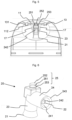
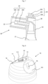
- the diffuser comprises a base body (10) provided with a finger cot (11), and an outlet conduit (20) located inside the base body.
- the finger cot (11) serves as a push button to move the outlet conduit (20) towards the aerosol generator in view to activate its valve.
- the outlet conduit (20) and the base body (10) are two separate parts, the outlet conduit being configured to be fixed by hooking means to the base body.
- the diffuser has a certain rotation geometry around a main axis (A).
- the adjectives “radial” and “axial” refer to this main axis.
- this main axis (A) is aligned with the stem of the valve, or more generally with the main axis of the valve body.
- the basic body is formed of a concave wall forming a cavity. Subsequently, the terms “interior” and “exterior” respectively qualify the elements which are in or towards the cavity and those which are outside or away from the cavity.
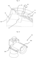
- the outlet conduit (20) has a first end (21) configured to cooperate with the valve; For this purpose it is provided at this first end with means for cooperating with the valve. If the valve is a female type valve, the end includes a stem intended to penetrate the valve to actuate it. If the valve is of the male type, the first end (21) is flared to facilitate the introduction of the stem when mounting the diffuser on the pressure vessel.
- the second end (22) of the outlet conduit opens outwards and can be fitted with a nozzle to improve the quality of the aerosol. If the product does not exit in alignment with the valve, the outlet conduit is divided between at least a first section (23) substantially rectilinear and a second section (24) inclined relative to the first.
- the first section begins at the first end (21) and ends at the junction with the second section (24), and the second section (24) begins at the junction with the first section (23) and ends at the second end (22).
- the second section (24) can be provided on the side of the second end with a nozzle housing (241).
- the second section (24) consists of an internal conduit (242) strictly speaking composing a part of the outlet conduit and which is surrounded by a cylindrical wall (243) at least on the side of the second end (22).
- the annular space between the inner conduit (242) and the cylindrical wall (243) constitutes the nozzle housing. If the diffuser is not equipped with a nozzle, it is possible to do without the cylindrical wall (243).
- hooking means are provided, a part of which located on the outlet conduit (20) cooperates with another complementary part made in the base body ( 10).
- the means for attaching the outlet conduit are constituted by a latching pin (25) intended to latch into a latching opening of the base body constituting the complementary part of the attachment means.
- the latching pin (25) is placed at the top of the 1st section (23), opposite the first end (21). It is preferably coaxial with the axis (A), but it is not imperative.
- the latching tenon consists of a substantially cylindrical rod (251) fixed by its first end to the outlet conduit and carrying at its second end a cap (252) of larger cross section.
- the junction between the rod (251) and the rest of the outlet conduit constitutes a shoulder (253) at a distance from the cap.
- the tenon is in fact a cylinder in which an annular groove is made.
- the top of the cylinder constitutes the cap (252), the annular groove forms the rod (251) and the part of the cylinder opposite the cap plays the role of shoulder (253).
- the base body (10) consists of a concave wall. In this example, it has a general dome shape. It could also be cylindrical.
- the base body (10) is provided with a fixing ring (12) configured to fix it either directly to the pressure vessel, in particular on the housing or the valve, or by means of a ferrule, particularly in the case of ON/OFF type diffusers.
- This fixing ring is provided with fixing means such as a series of gadroons (121) distributed regularly over the entire periphery of the fixing ring. These fixing means are intended to cooperate with complementary fixing means made on the housing or the valve of the pressure vessel, or on the ferrule.
- the gadroons (121) can snap into place behind the rolled edge at the interface between the housing and the valve cup or between the housing and the dome on which the valve cup is fixed.
- Other means of fixing can be considered, such as a continuous rib, a thread for screwing, an extra thickness of material for welding, glue for bonding, etc.
- the wall of the base body is pierced with a finger cot opening (13) in which the finger cot (11) is placed.
- the finger cot is fixed to the rest of the base body by a tab (14) which serves as a hinge so that when pressure is exerted on the finger cot towards the inside of the base body (therefore towards the valve when the diffuser is mounted on the pressure vessel), the finger cot pivots around an axis passing transversely through the tongue.
- the finger cot (11) and the corresponding opening (13) are placed towards the top of the base body.
- the projection of the finger cot (11) on a plane perpendicular to the main axis (A) covers at least the projection of the first section (23) of the outlet conduit on said plane perpendicular to the main axis (A). .
- the finger cot (11) is located above at least the top of the first section (23) of the outlet conduit.
- An opening (15) is made in the wall of the base body opposite the second end (22) of the outlet conduit.
- the product taken from the pressure vessel which leaves the outlet conduit through its second end (22) passes through this orifice (15).
- This orifice is preferably oblong and extends in an axial plane so that the 2nd end (22) of the outlet conduit, when it moves during actuation of the valve, always remains facing the the orifice (15).
- the second end (22) of the outlet conduit is therefore floating relative to the base body (10) and to the orifice (15) in particular.
- a hooking hole (16) is made in the base body (10) for fixing the outlet conduit (20).
- This hole constitutes the complementary hooking means for fixing the outlet conduit (20) to the base body (10).
- the hooking hole (16) is intended to receive and retain the hooking pin (15) of the outlet conduit. It passes right through the wall of the base body. In the example presented here, it is divided into two parts: an interior part (161) located towards the inside of the base body and an exterior part (162) opening onto the exterior face of the finger cot (11).
- the interior part (161) is dimensioned to receive the rod (251) of the hooking tenon while the exterior part, which is wider, is dimensioned to receive the cap (252) of the tenon.
- the exterior part (162) and the cap are preferably dimensioned so that the top of the cap is flush with the exterior face of the finger cot (11) and is in continuity with it.
- the length of the outer part (162) of the hanging hole (measured between the junction with the inner part (161) and the outer face of the wall of the base body) is preferably substantially identical to the height (measured between the junction of the cap with the stem and the top of the cap opposite the stem) of the cap (252).
- the top of the cap (252) is not perpendicular to the stem, but slightly inclined to follow the slope of the finger cot at this location.
- the cap (252) and the interior part (161) of the hooking hole are dimensioned so that the cap can pass by force through the stem portion when mounting the outlet conduit on the base body without requiring a excessive force which could break in particular the hooking pin (25).
- the cross section of the cap (252) is greater than the cross section of the interior part (161) of the hanging hole. More generally, it is sufficient that the greatest transverse extension of the cross section of the cap is greater than the greatest transverse extension of the cross section of the interior part of the hooking hole.
- the base body and/or outlet conduit are configured to keep the 2nd end of the outlet conduit aligned with the product outlet port (15).
- anti-rotation means can be provided.
- these anti-rotation means consist of two guide tabs (17). These guide tabs are located on the interior face of the base body, in this example on the interior face of the finger cot (11), between the hooking hole (16) and the product outlet orifice (15).
- the edge of the finger cot opening (13) can be continued by a skirt (131) directed towards the center, which skirt also serves as a cover when the finger cot (11) is pressed.
- the perimeter of the finger cot has a skirt (112) directed inwards. Stop ribs (18) can also be provided in the cavity of the base body to limit the sinking of the diffuser onto the housing of the pressure vessel.
- the outlet orifice (15) is placed in a recess (151) in the wall of the base body, which recess is more or less deformed, in particular concave considered from the outside of the base body, depending on the length of the second section (24) of the outlet conduit.
- the outlet conduit (20) is inserted into the cavity of the base body (10), with its second end (22) directed towards the outlet port (15).
- the hooking pin (25) is inserted into the hooking hole (16).
- the cap (252) passes by force through the interior part (161) until it emerges into the exterior part (162) whose cross section is sufficient to receive it.
- the rod (251) of the hooking pin is placed in the interior part (161) of the hooking hole and the shoulder (253) opposite the cap is in contact, or almost in contact, with the inner face of the finger cot (11).
- the second section (24) of the outlet conduit passes between the two guide tabs (17) which by their shape guide the outlet conduit exactly in alignment with the outlet orifice (15).
- outlet conduit is retained on the one hand in axial translation by blocking the wall of the finger cot at the level of the hooking hole between the cap (252) and the shoulder (253), and on the other hand in rotation by blocking the second section (24) between the two guide lugs (17).
- the cap (252) of the attachment pin of the outlet duct can blend in with these reliefs for a more aesthetic effect.
- the hat (252) is shorter than the outer part (162) of the hanging hole, so that it is not flush with the outer face of the finger cot and forms a hole similar to the other reliefs.
- the invention makes it possible to concentrate particularly on the outlet duct (20), which is essential for the spray quality, the rest of the diffuser, namely the basic body, being only a covering. It is possible to have very short channels, which is favorable particularly when using compressed gases.
- the base body and the outlet duct can be manufactured in different factories, which limits transportation problems.
- the same outlet duct can be used with base bodies of different color and/or material, and the same base body can be used with outlet ducts of different qualities. Many combinations are therefore possible.
- the invention it is possible to use two different materials for the outlet duct (20) and for the base body (10).
- the material of the outlet conduit will be chosen to be compatible with the product to be sampled, while the material of the base body will not need to fulfill this condition, but can be chosen for its mechanical properties in particular.
- the material of the outlet duct will need to be food grade, while that of the base body will not need to be and may be more economical.
- mechanical attachment means in particular by snap-fastening, it is not necessary for the two materials to be compatible with each other. It is also not necessary to provide a two-material injection.
- polymer materials (PE, PP, PLA, PHA, PBS) whether virgin or recycled, derived from petroleum or natural resources, biodegradable or not, even compostable or No. They can contain mineral fillers (glass, basalt), be reinforced with mineral or plant fibers.
- mineral fillers glass, basalt
- non-polymeric materials such as lignin-based materials (cardboard, wood), materials containing textiles, metals, etc.
- polymers PE, PP, POM, PBT, PA
- metals aluminum, steel, in particular stainless steel).
- the end of the rod, in particular the cap, and/or the hanging hole can be configured to transmit information to the user.
- the color and/or shape of the end of the rod, and in particular of the cap (252), can serve as information for the user, and in particular as means of identification.
- at least one of the two materials is a biomaterial or a recycled material, we could for example color the outlet conduit green so that the cap (252) forms a green patch on the finger cot.
- a manufacturer will thus be able to communicate with its customers about its strategic desire to be part of a sustainable development policy.
- outlet ducts To facilitate the handling of the outlet ducts, they can be fitted with assembly fins (244), particularly on the second section (24), which make it possible to correctly guide the outlet ducts in the assembly machine.
- the hooking pin can be at a certain distance from the junction between the first section (23) and the second section (24) of the outlet conduit, it is preferable to provide a recess (26) in the material located between this junction and the hooking pin.
- the shoulder (253) of the hooking pin is placed on the upper wall of this recess.
Landscapes
- Chemical & Material Sciences (AREA)
- Dispersion Chemistry (AREA)
- Engineering & Computer Science (AREA)
- Mechanical Engineering (AREA)
- Containers And Packaging Bodies Having A Special Means To Remove Contents (AREA)
- Nozzles (AREA)
- Check Valves (AREA)
- Filling Or Discharging Of Gas Storage Vessels (AREA)
- Catching Or Destruction (AREA)
- Structures Of Non-Positive Displacement Pumps (AREA)
- Coating Apparatus (AREA)
- Closures For Containers (AREA)
Claims (18)
- Diffusor für einen mit einem Ventil versehenen Druckbehälter, insbesondere für einen Aerosolgenerator, wobei der Diffusor (1) versehen ist mit- einem Grundkörper (10), der aus einer Wand mit einer einen Hohlraum bildenden konkaven Fläche gebildet ist und eine Fingerauflage (11) aufweist, die dazu bestimmt ist, vom Benutzer zur Betätigung des Ventils gedrückt zu werden, und- eine in dem Hohlraum des Grundkörpers (10) angeordnete Auslassleitung (20), die ein erstes Ende (21), das mit Mitteln zum Zusammenwirken mit dem Ventil des Druckbehälters versehen ist, und ein zweites Ende (22) für den Austritt des in dem Druckbehälter enthaltenen Produkts aufweist,wobei die Auslassleitung (20) und der Grundkörper (10) zwei getrennte Teile sind, die durch mechanische Befestigungsmittel (25, 16) miteinander verbunden sind, wobei Verdrehsicherungsmittel (17) vorgesehen sein können, um eine Drehung der Auslassleitung relativ zum Grundkörper zu verhindern,wobei die mechanischen Befestigungsmittel aus einem Befestigungszapfen (25) und einem Befestigungsloch (16) bestehen, wobei der Befestigungszapfen auf der Auslassleitung (20) angeordnet ist und das Befestigungsloch in der Wand des Grundkörpers (10) ausgebildet ist und in den Hohlraum mündet,wobei eine Öffnung (15) in der Wand des Grundkörpers gegenüber dem zweiten Ende (22) der Auslassleitung und in einem Abstand von dem Befestigungsloch (16) ausgebildet ist,dadurch gekennzeichnet, dass
das Befestigungsloch (16) ein Loch ist, das durch die Wand des Grundkörpers hindurchgeht und dazu bestimmt ist, den Befestigungszapfen (15) der Auslassleitung aufzunehmen und zu halten. - Diffusor nach dem vorhergehenden Anspruch, dadurch gekennzeichnet, dass das dem Rest der Auslassleitung (20) gegenüberliegende Ende des Befestigungszapfens (25) eine besondere Form und/oder Farbe aufweist, die im befestigten Zustand der Auslassleitung von der Außenseite des Diffusors her sichtbar und erkennbar ist/sind und ein Identifikations- oder Informationsmittel für den Benutzer darstellt/darstellen.
- Diffusor nach einem der vorhergehenden Ansprüche, dadurch gekennzeichnet, dass- das Befestigungsloch (16) in der Fingerauflage (11) des Grundkörpers (10) ausgebildet ist,- der Befestigungszapfen (25) eine Kappe (252) aufweist, die mit der Auslassleitung durch eine Stange (251) verbunden ist, die mit einer Schulter (253) gegenüber der Kappe endet,- das Befestigungsloch (16) mindestens einen ersten Abschnitt, genannt Innenabschnitt (161), aufweist, dessen größte Querausdehnung geringer ist als die größte Querausdehnung der Kappe (252) des Befestigungszapfens, wobei eine Länge der Stange (251) des Zapfens so gewählt ist, dass im befestigten Zustand der Auslassleitung die Wand des Grundkörpers (10) am Rand des Befestigungslochs (16) zwischen der Kappe (252) und der Schulter (253) liegt, wobei ein Querschnitt der Kappe (252) und ein Querschnitt des Innenabschnitts (161) so gewählt sind, dass bei der Befestigung der Auslassleitung die Kappe unter Kraftaufwand in den Innenabschnitt (161) des Befestigungslochs eingeführt werden kann, ohne eine Beschädigung der Auslassleitung oder des Grundkörpers (10) zu riskieren.
- Diffusor nach dem vorhergehenden Anspruch, dadurch gekennzeichnet, dass der Innenabschnitt (161) des Befestigungslochs (16) in einen zweiten Abschnitt, genannt Außenabschnitt (162), übergeht, wobei der Innenabschnitt in den Hohlraum des Grundkörpers (10) mündet und der Außenabschnitt an der Außenseite des Grundkörpers (10) ausläuft, wobei ein Querschnitt des Außenabschnitts (162) so bemessen ist, dass er einen Querschnitt der Kappe (252) des Befestigungszapfens aufnimmt, wobei eine Länge des Außenabschnitts (162) des Befestigungslochs vorzugsweise im Wesentlichen identisch mit einer Höhe der Kappe (252) ist, so dass letztere mit der Außenfläche des Grundkörpers bündig ist.
- Diffusor nach einem der vorhergehenden Ansprüche, dadurch gekennzeichnet, dass- die Auslassleitung (20) einen ersten Abschnitt (23), der im Wesentlichen geradlinig ist, und einen zweiten Abschnitt (24) umfasst, wobei der erste Abschnitt am ersten Ende (21) der Auslassleitung beginnt und an der Verbindung mit dem zweiten Abschnitt (24) endet,- der Befestigungszapfen (25) an dem oberen Ende des ersten Abschnitts (23) auf der gegenüberliegenden Seite des ersten Endes (21) oder am zweiten Abschnitt (24) angeordnet ist,- die Befestigungsloch (16) in der Fingerauflage (11) ausgebildet ist.
- Diffusor nach einem der vorhergehenden Ansprüche, dadurch gekennzeichnet, dass die Verdrehsicherungmittel durch einen festen Sitz des Befestigungszapfens (25) in dem Befestigungsloch (16) gebildet sind, wobei ein Querschnitt des Befestigungszapfens, insbesondere der Stange (251) des Befestigungszapfens, wenn der Befestigungszapfen mit einer Stange versehen ist, vorzugsweise größer ist als ein Querschnitt zumindest eines Teils des Befestigungslochs (16), insbesondere des Innenabschnitts (161) des Befestigungslochs, wenn das Befestigungsloch mit einem Innenabschnitt versehen ist.
- Diffusor nach einem der vorangehenden Ansprüche, dadurch gekennzeichnet, dass die Verdrehsicherungmittel durch einen Formschluß des Befestigungszapfens (25) in dem Befestigungsloch (16), insbesondere der Stange (251) des Befestigungszapfens in dem Innenabschnitt (161) des Befestigungslochs, wenn der Befestigungszapfen mit einer Stange versehen ist und wenn das Befestigungsloch mit einem Innenabschnitt versehen ist, gebildet sind, wobei ein Querschnitt des Befestigungszapfens, insbesondere der Stange (251) des Befestigungszapfens, wenn der Befestigungszapfen mit einer Stange versehen ist, und ein Querschnitt des Befestigungslochs, insbesondere des Innenabschnitts (161) des Befestigungslochs, wenn das Befestigungsloch mit einem Innenabschnitt versehen ist, keine Drehsymmetrie aufweisen und vorzugsweise komplementär sind.
- Diffusor nach Anspruch 4 oder einem der Ansprüche 5 bis 7 in Verbindung mit Anspruch 4, dadurch gekennzeichnet, dass die Verdrehsicherungmittel durch einen Formschluß der Kappe (252) des Befestigungszapfens im Außenabschnitt (162) des Befestigungslochs gebildet sind, wobei der Querschnitt der Kappe (252) des Befestigungszapfens und der Querschnitt des Außenabschnitts (162) des Befestigungslochs keine Drehsymmetrie aufweisen und vorzugsweise komplementär sind.
- Diffusor nach einem der vorhergehenden Ansprüche, dadurch gekennzeichnet, dass die Verdrehsicherungmittel aus zwei Führungslaschen (17) bestehen, die im Hohlraum des Grundkörpers angeordnet sind und einen Teil der Auslassleitung, insbesondere den zweiten Abschnitt (24), wenn die Auslassleitung mit einem zweiten Teil versehen ist, umgreifen, wodurch diese daran gehindert wird, sich um den Befestigungszapfen (25) zu drehen.
- Diffusor nach einem der vorhergehenden Ansprüche, dadurch gekennzeichnet, dass das für den Grundkörper verwendete Material und das für die Auslassleitung verwendete Material unterschiedliche Zusammensetzungen und/oder Farben aufweisen.
- Diffusor nach Anspruch 3 oder einem der Ansprüche 4 bis 10 in Verbindung mit Anspruch 3, dadurch gekennzeichnet, dass die Kappe (252) eine besondere Form und/oder Farbe aufweist, die im befestigten Zustand der Auslassleitung von der Außenseite des Diffusors her sichtbar und erkennbar ist/sind und Identifikations- oder Informationsmittel für den Benutzer darstellt/darstellen.
- Diffusor nach einem der vorhergehenden Ansprüche, dadurch gekennzeichnet, dass der Grundkörper mit Befestigungsmitteln (121) versehen ist, um ihn direkt oder über eine Zwinge an einem Druckbehälter zu befestigen.
- Diffusor nach einem der vorhergehenden Ansprüche, dadurch gekennzeichnet, dass die in der Wand des Grundkörpers ausgebildete Öffnung (15) in einer Vertiefung (151) der Wand des Grundkörpers angeordnet ist, wobei die Vertiefung, von der Außenseite des Grundkörpers aus betrachtet, vorzugsweise eine konkave Form aufweist.
- Diffusor nach einem der vorhergehenden Ansprüche, dadurch gekennzeichnet, dass zumindest ein Teil des Grundkörpers (10) und/oder zumindest ein Teil der Auslassleitung (20) aus einem Recyclingmaterial, aus einem biologisch abbaubaren Material, aus einem kompostierbaren Material oder aus einem Biomaterial oder einer Mischung davon hergestellt ist/sind.
- Diffusor nach einem der vorhergehenden Ansprüche, dadurch gekennzeichnet, dass der Grundkörper (10) aus einem Material hergestellt ist, das ausgewählt ist aus:- einem Polymerwerkstoff, vorzugsweise Polyethylen (PE), Polypropylen (PP), Polylactide (PLA), Polyhydroxyalkanoate (PHA), Polybutylensuccinat (PBS) oder einer Mischung davon, wobei das Polymer Mineralfüllstoffe, insbesondere Glas und/oder Basalt, enthalten und/oder mit mineralischen oder pflanzlichen Fasern verstärkt sein kann,- ein Material auf Ligninbasis, vorzugsweise Karton und/oder Holz,- ein textilhaltiges Material,- ein Metall,- eine Mischung aus diesen Materialien.
- Diffusor nach einem der vorhergehenden Ansprüche, dadurch gekennzeichnet, dass die Auslassleitung (20) aus einem lebensmittelverträglichen und/oder kosmetisch verträglichen und/oder pharmazeutisch verträglichen und/oder medizinisch verträglichen Material hergestellt ist.
- Diffusor nach einem der vorhergehenden Ansprüche, dadurch gekennzeichnet, dass die Auslassleitung (20) aus einem Material hergestellt ist, das ausgewählt ist aus:- einem Polymermaterial, vorzugsweise Polyethylen (PE), Polypropylen (PP), Polyoxymethylen (POM), Polybutylenterephthalat (PBT), Polyamid (PA) oder einer Mischung davon,- ein Metall, vorzugsweise Aluminium oder Stahl, insbesondere rostfreier Stahl.
- Diffusor nach einem der vorhergehenden Ansprüche, dadurch gekennzeichnet, dass die Auslassleitung (20) aus einem neuen Material und der Hauptkörper zumindest teilweise aus einem Recyclingmaterial hergestellt ist.
Applications Claiming Priority (2)
| Application Number | Priority Date | Filing Date | Title |
|---|---|---|---|
| FR1900676A FR3092091B1 (fr) | 2019-01-25 | 2019-01-25 | Diffuseur pour récipient sous pression |
| PCT/EP2020/051372 WO2020152141A1 (fr) | 2019-01-25 | 2020-01-21 | Diffuseur pour récipient sous pression |
Publications (3)
| Publication Number | Publication Date |
|---|---|
| EP3914534A1 EP3914534A1 (de) | 2021-12-01 |
| EP3914534C0 EP3914534C0 (de) | 2024-02-28 |
| EP3914534B1 true EP3914534B1 (de) | 2024-02-28 |
Family
ID=66867418
Family Applications (4)
| Application Number | Title | Priority Date | Filing Date |
|---|---|---|---|
| EP20700735.2A Active EP3914532B1 (de) | 2019-01-25 | 2020-01-21 | Diffusorauslasskanal |
| EP20701453.1A Active EP3914534B1 (de) | 2019-01-25 | 2020-01-21 | Diffusor für druckbehälter |
| EP20700736.0A Active EP3914533B1 (de) | 2019-01-25 | 2020-01-21 | Spender für druckbehälter |
| EP20700734.5A Active EP3914531B1 (de) | 2019-01-25 | 2020-01-21 | Spender für druckbehälter |
Family Applications Before (1)
| Application Number | Title | Priority Date | Filing Date |
|---|---|---|---|
| EP20700735.2A Active EP3914532B1 (de) | 2019-01-25 | 2020-01-21 | Diffusorauslasskanal |
Family Applications After (2)
| Application Number | Title | Priority Date | Filing Date |
|---|---|---|---|
| EP20700736.0A Active EP3914533B1 (de) | 2019-01-25 | 2020-01-21 | Spender für druckbehälter |
| EP20700734.5A Active EP3914531B1 (de) | 2019-01-25 | 2020-01-21 | Spender für druckbehälter |
Country Status (7)
| Country | Link |
|---|---|
| US (4) | US11643267B2 (de) |
| EP (4) | EP3914532B1 (de) |
| AR (4) | AR117857A1 (de) |
| CA (4) | CA3126616A1 (de) |
| FR (1) | FR3092091B1 (de) |
| MX (5) | MX2021007737A (de) |
| WO (4) | WO2020152127A1 (de) |
Families Citing this family (3)
| Publication number | Priority date | Publication date | Assignee | Title |
|---|---|---|---|---|
| FR3092091B1 (fr) * | 2019-01-25 | 2021-08-13 | Lindal France | Diffuseur pour récipient sous pression |
| FR3099470B1 (fr) | 2019-07-29 | 2021-09-10 | Lindal France | Valve pour récipient sous pression |
| ES1285316Y (es) * | 2021-11-03 | 2022-04-20 | Zenit Estudio De Diseno E Innovacion S L | Tapa actuadora con tambor interior |
Family Cites Families (51)
| Publication number | Priority date | Publication date | Assignee | Title |
|---|---|---|---|---|
| US3058626A (en) * | 1959-06-22 | 1962-10-16 | George W Hibbs | Cap for spray dispenser, or the like |
| US3567081A (en) * | 1969-01-30 | 1971-03-02 | Philip Meshberg | Multidirectional aerosol dispenser |
| US3858762A (en) * | 1972-11-09 | 1975-01-07 | Philip Meshberg | Actuator assembly for an encased dispenser and method |
| US4019584A (en) * | 1975-12-01 | 1977-04-26 | Richmond Industries, Inc. | Fire extinguisher |
| FR2429161A1 (fr) | 1978-06-19 | 1980-01-18 | Aerosol Inventions Dev | Ensemble de distribution pour valve aerosol |
| US4328911A (en) | 1980-07-23 | 1982-05-11 | Seaquist Valve Company | Child resistant aerosol actuating overcap |
| US4416399A (en) | 1981-06-12 | 1983-11-22 | Ziphron, Inc. | Aerosol canister |
| GB8306856D0 (en) * | 1983-03-12 | 1983-04-20 | Metal Box Plc | Aerosol actuator |
| FR2556242B1 (fr) * | 1983-12-07 | 1986-08-22 | Aerosol Inventions Dev | Diffuseur de produits d'ambiance a double action, immediate et differee, et conditionnement aerosol equipe d'un tel diffuseur |
| KR880701137A (ko) * | 1986-04-25 | 1988-07-25 | 이시바시 유끼히로 | 보호캪을 갖는 분사헤드 |
| US4815541A (en) | 1987-06-29 | 1989-03-28 | Arrington Richard C | Fire extinguisher |
| JPH0835971A (ja) * | 1994-07-25 | 1996-02-06 | Hitachi Ltd | ピペット |
| FR2767799B1 (fr) * | 1997-08-27 | 2000-05-12 | Oreal | Ensemble de conditionnement d'un produit liquide ou semi-liquide |
| GB9727366D0 (en) * | 1997-12-24 | 1998-02-25 | Unilever Plc | Sprayhead |
| US6006957A (en) | 1998-03-06 | 1999-12-28 | S. C. Johnson & Son, Inc. | Actuator overcap for a pressurized canister |
| GB0003343D0 (en) * | 2000-02-14 | 2000-04-05 | Unilever Plc | Actuator mechanism |
| US7320417B2 (en) | 2000-06-10 | 2008-01-22 | Wella Ag | Container |
| US6454139B1 (en) * | 2001-02-14 | 2002-09-24 | Precision Valve Corporation | Preassembled aerosol actuator assembly for in-line capping to an aerosol container |
| FR2839952B1 (fr) * | 2002-05-24 | 2004-08-06 | Oreal | Dispositif de distribution destine a equiper un recipient muni d'une valve |
| US6908017B2 (en) | 2003-06-05 | 2005-06-21 | S. C. Johnson & Son, Inc. | Aerosol over cap with flip-up closure |
| ATE429391T1 (de) * | 2004-03-18 | 2009-05-15 | Rust Oleum Netherlands B V | Abgabevorrichtung zum abgeben eines produkts |
| DE102004022131A1 (de) | 2004-05-05 | 2005-11-24 | Boehringer Ingelheim Microparts Gmbh | Sprühkopf zum Atomisieren eines Mediums |
| US20070290007A1 (en) * | 2004-11-30 | 2007-12-20 | The Procter & Gamble Company | Cap with an angled spray channel for an aerosol container or a spray container |
| FR2881721A1 (fr) * | 2005-02-09 | 2006-08-11 | Innovation Packaging Sarl | Bouton poussoir |
| PL1901631T3 (pl) | 2005-06-16 | 2012-08-31 | Colgate Palmolive Europe Sarl | Środek przeciwpotowy na bazie wody i dozownik aerozolowy do niego |
| DE602006017219D1 (de) * | 2005-07-18 | 2010-11-11 | Aerosol Service Ag | Sprühvorrichtung zur abgabe einer kühlenden flüssigkeit |
| US7204393B2 (en) * | 2005-08-12 | 2007-04-17 | Summit Packaging, Inc. | Spray actuating mechanism for a dispensing canister |
| US20070051754A1 (en) * | 2005-09-08 | 2007-03-08 | Strand Toralf H | Button actuated mechanism for a dispensing canister |
| WO2007112310A2 (en) * | 2006-03-24 | 2007-10-04 | Colgate-Palmolive Company | Aerosol dispenser |
| US7530476B2 (en) * | 2006-04-10 | 2009-05-12 | Precision Valve Corporation | Locking aerosol dispenser |
| US8960503B2 (en) * | 2006-10-19 | 2015-02-24 | Atef Gabr Soliman | Plastic aerosol container |
| DE102007049614B4 (de) * | 2007-03-15 | 2015-03-05 | Aptar Dortmund Gmbh | Abgabevorrichtung |
| US7789278B2 (en) * | 2007-04-12 | 2010-09-07 | The Clorox Company | Dual chamber aerosol container |
| US8881944B2 (en) | 2008-06-30 | 2014-11-11 | S.C. Johnson & Son, Inc. | Overcap for and a method of actuating a volatile material dispenser |
| EP2551214A4 (de) | 2010-03-12 | 2017-12-27 | Mitani Valve Co., Ltd. | Behälterabdeckung und aerosolprodukt mit der behälterabdeckung |
| DE202011000160U1 (de) | 2011-01-21 | 2012-04-23 | Lindal Dispenser Gmbh | Sprühkopf |
| US9981799B2 (en) | 2011-08-09 | 2018-05-29 | S.C. Johnson & Son, Inc. | Dispensing system |
| DE102012200545A1 (de) * | 2012-01-16 | 2013-07-18 | Aptar Radolfzell Gmbh | Medienspender |
| US9435120B2 (en) * | 2013-03-13 | 2016-09-06 | Homax Products, Inc. | Acoustic ceiling popcorn texture materials, systems, and methods |
| JP5901564B2 (ja) * | 2013-04-03 | 2016-04-13 | 東洋エアゾール工業株式会社 | エアゾール容器用固定盤 |
| CA2859537C (en) | 2013-08-19 | 2019-10-29 | Homax Products, Inc. | Ceiling texture materials, systems, and methods |
| ES2640713T3 (es) * | 2013-12-09 | 2017-11-06 | Unilever Nv | Cabezal dispensador de aerosol |
| US20160221744A1 (en) * | 2015-01-29 | 2016-08-04 | Tremco Illbruck Productie B.V. | Dispenser head |
| FR3035380B3 (fr) * | 2015-04-24 | 2017-05-12 | Lindal France | Tete de distribution pour recipient aerosol munie de moyens de blocage |
| US9862535B2 (en) | 2016-02-12 | 2018-01-09 | S. C. Johnson & Son, Inc. | Overcap assembly |
| EP3251753B1 (de) | 2016-06-01 | 2019-07-31 | Aptar Radolfzell GmbH | Spender zum austrag einer flüssigkeit |
| DE102016221820A1 (de) | 2016-11-08 | 2018-05-09 | Beiersdorf Ag | Selbstschließender Ausgabekopf |
| US11034507B2 (en) | 2018-08-27 | 2021-06-15 | S. C. Johnson & Son, Inc. | Trigger overcap assembly |
| US11267644B2 (en) * | 2018-11-08 | 2022-03-08 | The Procter And Gamble Company | Aerosol foam dispenser and methods for delivering a textured foam product |
| FR3092091B1 (fr) | 2019-01-25 | 2021-08-13 | Lindal France | Diffuseur pour récipient sous pression |
| FR3106338A1 (fr) | 2020-01-21 | 2021-07-23 | Lindal France | Diffuseur pour récipient sous pression |
-
2019
- 2019-01-25 FR FR1900676A patent/FR3092091B1/fr not_active Expired - Fee Related
-
2020
- 2020-01-21 WO PCT/EP2020/051337 patent/WO2020152127A1/fr not_active Ceased
- 2020-01-21 EP EP20700735.2A patent/EP3914532B1/de active Active
- 2020-01-21 EP EP20701453.1A patent/EP3914534B1/de active Active
- 2020-01-21 MX MX2021007737A patent/MX2021007737A/es unknown
- 2020-01-21 CA CA3126616A patent/CA3126616A1/fr active Pending
- 2020-01-21 EP EP20700736.0A patent/EP3914533B1/de active Active
- 2020-01-21 AR ARP200100148A patent/AR117857A1/es active IP Right Grant
- 2020-01-21 AR ARP200100142A patent/AR117852A1/es active IP Right Grant
- 2020-01-21 US US17/423,987 patent/US11643267B2/en active Active
- 2020-01-21 WO PCT/EP2020/051372 patent/WO2020152141A1/fr not_active Ceased
- 2020-01-21 US US17/423,963 patent/US11661265B2/en active Active
- 2020-01-21 WO PCT/EP2020/051336 patent/WO2020152126A1/fr not_active Ceased
- 2020-01-21 MX MX2021008844A patent/MX2021008844A/es unknown
- 2020-01-21 US US17/423,974 patent/US12037181B2/en active Active
- 2020-01-21 WO PCT/EP2020/051335 patent/WO2020152125A1/fr not_active Ceased
- 2020-01-21 US US17/420,380 patent/US11667461B2/en active Active
- 2020-01-21 CA CA3121314A patent/CA3121314A1/fr active Pending
- 2020-01-21 MX MX2021008846A patent/MX2021008846A/es unknown
- 2020-01-21 MX MX2021008841A patent/MX2021008841A/es unknown
- 2020-01-21 CA CA3126617A patent/CA3126617A1/fr active Pending
- 2020-01-21 EP EP20700734.5A patent/EP3914531B1/de active Active
- 2020-01-21 AR ARP200100141A patent/AR117851A1/es active IP Right Grant
- 2020-01-21 AR ARP200100143A patent/AR117853A1/es active IP Right Grant
- 2020-01-21 CA CA3126619A patent/CA3126619A1/fr active Pending
-
2021
- 2021-07-22 MX MX2024009517A patent/MX2024009517A/es unknown
Also Published As
Similar Documents
| Publication | Publication Date | Title |
|---|---|---|
| EP1201318B1 (de) | Abgabeeinheit für die gleichzeitige Abgabe von zwei Produkten | |
| EP3914534B1 (de) | Diffusor für druckbehälter | |
| EP2084073B1 (de) | Modularer behälter zur aufnahme von gegen luftkontakt anfällige waren | |
| EP0755872B1 (de) | Mit einer Abgabeöffnung und einer Verschlussvorrichtung versehener Behälter | |
| EP3603817B1 (de) | Erleichterte montage und demontage einer pumpe in bezug auf einen reservoir | |
| WO2018115685A1 (fr) | Dispositif rechargeable de conditionnement d'un produit cosmétique | |
| WO2006129043A2 (fr) | Ensemble de fixation d'un organe de distribution de produit fluide | |
| EP2442914B1 (de) | Flüssigmaterialspender | |
| EP1751023B1 (de) | Verteilvorrichtung für parfum | |
| FR2767794A1 (fr) | Ensemble de deux elements montes libres en rotation l'un par rapport a l'autre notamment pour un melangeur dans le domaine de la coloration capillaire | |
| FR2975674A1 (fr) | Bague de fixation et distributeur de produit fluide utilisant une telle bague. | |
| EP3129157A1 (de) | Flasche und herstellungsverfahren dafür | |
| FR2916743A1 (fr) | Dispositif de fixation pour fixer une pompe sur un reservoir et distributeur utilisant un tel dispositif de fixation | |
| EP3953050B1 (de) | Spender für druckbehälter | |
| EP4244157A1 (de) | Diffusor für aerosolgenerator | |
| FR3139556A1 (fr) | Ensemble de conditionnement de produit cosmétique comprenant un récipient en matériau cellulosique et un élément d’obturation | |
| WO2021148382A1 (fr) | Diffuseur pour récipient sous pression | |
| EP1442998B1 (de) | Elastische Verschlussvorrichtung und Behälter | |
| FR2630403A1 (fr) | Bouchon a obturateur pivotant pour la distribution de matieres liquides ou pateuses | |
| FR2868262A1 (fr) | Corps de distributeur de produit en matiere plastique et a fond mobile |
Legal Events
| Date | Code | Title | Description |
|---|---|---|---|
| STAA | Information on the status of an ep patent application or granted ep patent |
Free format text: STATUS: UNKNOWN |
|
| STAA | Information on the status of an ep patent application or granted ep patent |
Free format text: STATUS: THE INTERNATIONAL PUBLICATION HAS BEEN MADE |
|
| PUAI | Public reference made under article 153(3) epc to a published international application that has entered the european phase |
Free format text: ORIGINAL CODE: 0009012 |
|
| STAA | Information on the status of an ep patent application or granted ep patent |
Free format text: STATUS: REQUEST FOR EXAMINATION WAS MADE |
|
| 17P | Request for examination filed |
Effective date: 20210722 |
|
| AK | Designated contracting states |
Kind code of ref document: A1 Designated state(s): AL AT BE BG CH CY CZ DE DK EE ES FI FR GB GR HR HU IE IS IT LI LT LU LV MC MK MT NL NO PL PT RO RS SE SI SK SM TR |
|
| DAV | Request for validation of the european patent (deleted) | ||
| DAX | Request for extension of the european patent (deleted) | ||
| RAP3 | Party data changed (applicant data changed or rights of an application transferred) |
Owner name: LINDAL FRANCE SAS |
|
| STAA | Information on the status of an ep patent application or granted ep patent |
Free format text: STATUS: EXAMINATION IS IN PROGRESS |
|
| 17Q | First examination report despatched |
Effective date: 20220809 |
|
| GRAP | Despatch of communication of intention to grant a patent |
Free format text: ORIGINAL CODE: EPIDOSNIGR1 |
|
| STAA | Information on the status of an ep patent application or granted ep patent |
Free format text: STATUS: GRANT OF PATENT IS INTENDED |
|
| INTG | Intention to grant announced |
Effective date: 20230918 |
|
| GRAS | Grant fee paid |
Free format text: ORIGINAL CODE: EPIDOSNIGR3 |
|
| GRAA | (expected) grant |
Free format text: ORIGINAL CODE: 0009210 |
|
| STAA | Information on the status of an ep patent application or granted ep patent |
Free format text: STATUS: THE PATENT HAS BEEN GRANTED |
|
| AK | Designated contracting states |
Kind code of ref document: B1 Designated state(s): AL AT BE BG CH CY CZ DE DK EE ES FI FR GB GR HR HU IE IS IT LI LT LU LV MC MK MT NL NO PL PT RO RS SE SI SK SM TR |
|
| REG | Reference to a national code |
Ref country code: GB Ref legal event code: FG4D Free format text: NOT ENGLISH |
|
| REG | Reference to a national code |
Ref country code: CH Ref legal event code: EP |
|
| REG | Reference to a national code |
Ref country code: DE Ref legal event code: R096 Ref document number: 602020026369 Country of ref document: DE |
|
| REG | Reference to a national code |
Ref country code: IE Ref legal event code: FG4D Free format text: LANGUAGE OF EP DOCUMENT: FRENCH |
|
| U01 | Request for unitary effect filed |
Effective date: 20240305 |
|
| U07 | Unitary effect registered |
Designated state(s): AT BE BG DE DK EE FI FR IT LT LU LV MT NL PT SE SI Effective date: 20240313 |
|
| PG25 | Lapsed in a contracting state [announced via postgrant information from national office to epo] |
Ref country code: IS Free format text: LAPSE BECAUSE OF FAILURE TO SUBMIT A TRANSLATION OF THE DESCRIPTION OR TO PAY THE FEE WITHIN THE PRESCRIBED TIME-LIMIT Effective date: 20240628 |
|
| PG25 | Lapsed in a contracting state [announced via postgrant information from national office to epo] |
Ref country code: GR Free format text: LAPSE BECAUSE OF FAILURE TO SUBMIT A TRANSLATION OF THE DESCRIPTION OR TO PAY THE FEE WITHIN THE PRESCRIBED TIME-LIMIT Effective date: 20240529 |
|
| PG25 | Lapsed in a contracting state [announced via postgrant information from national office to epo] |
Ref country code: RS Free format text: LAPSE BECAUSE OF FAILURE TO SUBMIT A TRANSLATION OF THE DESCRIPTION OR TO PAY THE FEE WITHIN THE PRESCRIBED TIME-LIMIT Effective date: 20240528 Ref country code: HR Free format text: LAPSE BECAUSE OF FAILURE TO SUBMIT A TRANSLATION OF THE DESCRIPTION OR TO PAY THE FEE WITHIN THE PRESCRIBED TIME-LIMIT Effective date: 20240228 |
|
| PG25 | Lapsed in a contracting state [announced via postgrant information from national office to epo] |
Ref country code: ES Free format text: LAPSE BECAUSE OF FAILURE TO SUBMIT A TRANSLATION OF THE DESCRIPTION OR TO PAY THE FEE WITHIN THE PRESCRIBED TIME-LIMIT Effective date: 20240228 |
|
| PG25 | Lapsed in a contracting state [announced via postgrant information from national office to epo] |
Ref country code: RS Free format text: LAPSE BECAUSE OF FAILURE TO SUBMIT A TRANSLATION OF THE DESCRIPTION OR TO PAY THE FEE WITHIN THE PRESCRIBED TIME-LIMIT Effective date: 20240528 Ref country code: NO Free format text: LAPSE BECAUSE OF FAILURE TO SUBMIT A TRANSLATION OF THE DESCRIPTION OR TO PAY THE FEE WITHIN THE PRESCRIBED TIME-LIMIT Effective date: 20240528 Ref country code: IS Free format text: LAPSE BECAUSE OF FAILURE TO SUBMIT A TRANSLATION OF THE DESCRIPTION OR TO PAY THE FEE WITHIN THE PRESCRIBED TIME-LIMIT Effective date: 20240628 Ref country code: HR Free format text: LAPSE BECAUSE OF FAILURE TO SUBMIT A TRANSLATION OF THE DESCRIPTION OR TO PAY THE FEE WITHIN THE PRESCRIBED TIME-LIMIT Effective date: 20240228 Ref country code: GR Free format text: LAPSE BECAUSE OF FAILURE TO SUBMIT A TRANSLATION OF THE DESCRIPTION OR TO PAY THE FEE WITHIN THE PRESCRIBED TIME-LIMIT Effective date: 20240529 Ref country code: ES Free format text: LAPSE BECAUSE OF FAILURE TO SUBMIT A TRANSLATION OF THE DESCRIPTION OR TO PAY THE FEE WITHIN THE PRESCRIBED TIME-LIMIT Effective date: 20240228 |
|
| PG25 | Lapsed in a contracting state [announced via postgrant information from national office to epo] |
Ref country code: PL Free format text: LAPSE BECAUSE OF FAILURE TO SUBMIT A TRANSLATION OF THE DESCRIPTION OR TO PAY THE FEE WITHIN THE PRESCRIBED TIME-LIMIT Effective date: 20240228 |
|
| PG25 | Lapsed in a contracting state [announced via postgrant information from national office to epo] |
Ref country code: PL Free format text: LAPSE BECAUSE OF FAILURE TO SUBMIT A TRANSLATION OF THE DESCRIPTION OR TO PAY THE FEE WITHIN THE PRESCRIBED TIME-LIMIT Effective date: 20240228 |
|
| PG25 | Lapsed in a contracting state [announced via postgrant information from national office to epo] |
Ref country code: SM Free format text: LAPSE BECAUSE OF FAILURE TO SUBMIT A TRANSLATION OF THE DESCRIPTION OR TO PAY THE FEE WITHIN THE PRESCRIBED TIME-LIMIT Effective date: 20240228 |
|
| PG25 | Lapsed in a contracting state [announced via postgrant information from national office to epo] |
Ref country code: SK Free format text: LAPSE BECAUSE OF FAILURE TO SUBMIT A TRANSLATION OF THE DESCRIPTION OR TO PAY THE FEE WITHIN THE PRESCRIBED TIME-LIMIT Effective date: 20240228 |
|
| PG25 | Lapsed in a contracting state [announced via postgrant information from national office to epo] |
Ref country code: SM Free format text: LAPSE BECAUSE OF FAILURE TO SUBMIT A TRANSLATION OF THE DESCRIPTION OR TO PAY THE FEE WITHIN THE PRESCRIBED TIME-LIMIT Effective date: 20240228 Ref country code: SK Free format text: LAPSE BECAUSE OF FAILURE TO SUBMIT A TRANSLATION OF THE DESCRIPTION OR TO PAY THE FEE WITHIN THE PRESCRIBED TIME-LIMIT Effective date: 20240228 Ref country code: RO Free format text: LAPSE BECAUSE OF FAILURE TO SUBMIT A TRANSLATION OF THE DESCRIPTION OR TO PAY THE FEE WITHIN THE PRESCRIBED TIME-LIMIT Effective date: 20240228 |
|
| REG | Reference to a national code |
Ref country code: DE Ref legal event code: R097 Ref document number: 602020026369 Country of ref document: DE |
|
| PLBE | No opposition filed within time limit |
Free format text: ORIGINAL CODE: 0009261 |
|
| STAA | Information on the status of an ep patent application or granted ep patent |
Free format text: STATUS: NO OPPOSITION FILED WITHIN TIME LIMIT |
|
| U20 | Renewal fee for the european patent with unitary effect paid |
Year of fee payment: 6 Effective date: 20241204 |
|
| 26N | No opposition filed |
Effective date: 20241129 |
|
| REG | Reference to a national code |
Ref country code: CH Ref legal event code: PL |
|
| PG25 | Lapsed in a contracting state [announced via postgrant information from national office to epo] |
Ref country code: MC Free format text: LAPSE BECAUSE OF FAILURE TO SUBMIT A TRANSLATION OF THE DESCRIPTION OR TO PAY THE FEE WITHIN THE PRESCRIBED TIME-LIMIT Effective date: 20240228 |
|
| PG25 | Lapsed in a contracting state [announced via postgrant information from national office to epo] |
Ref country code: CH Free format text: LAPSE BECAUSE OF NON-PAYMENT OF DUE FEES Effective date: 20250131 |
|
| PG25 | Lapsed in a contracting state [announced via postgrant information from national office to epo] |
Ref country code: IE Free format text: LAPSE BECAUSE OF NON-PAYMENT OF DUE FEES Effective date: 20250121 |
|
| U20 | Renewal fee for the european patent with unitary effect paid |
Year of fee payment: 7 Effective date: 20260114 |
|
| PGFP | Annual fee paid to national office [announced via postgrant information from national office to epo] |
Ref country code: GB Payment date: 20260122 Year of fee payment: 7 |
|
| PGFP | Annual fee paid to national office [announced via postgrant information from national office to epo] |
Ref country code: CZ Payment date: 20260108 Year of fee payment: 7 |