EP3914802B1 - Expandierbarer metallpacker mit verankerungssystem - Google Patents
Expandierbarer metallpacker mit verankerungssystem Download PDFInfo
- Publication number
- EP3914802B1 EP3914802B1 EP20701464.8A EP20701464A EP3914802B1 EP 3914802 B1 EP3914802 B1 EP 3914802B1 EP 20701464 A EP20701464 A EP 20701464A EP 3914802 B1 EP3914802 B1 EP 3914802B1
- Authority
- EP
- European Patent Office
- Prior art keywords
- base pipe
- packer
- anchoring system
- extremities
- expandable metal
- Prior art date
- Legal status (The legal status is an assumption and is not a legal conclusion. Google has not performed a legal analysis and makes no representation as to the accuracy of the status listed.)
- Active
Links
Images




Classifications
-
- E—FIXED CONSTRUCTIONS
- E21—EARTH OR ROCK DRILLING; MINING
- E21B—EARTH OR ROCK DRILLING; OBTAINING OIL, GAS, WATER, SOLUBLE OR MELTABLE MATERIALS OR A SLURRY OF MINERALS FROM WELLS
- E21B23/00—Apparatus for displacing, setting, locking, releasing or removing tools, packers or the like in boreholes or wells
- E21B23/01—Apparatus for displacing, setting, locking, releasing or removing tools, packers or the like in boreholes or wells for anchoring the tools or the like
-
- E—FIXED CONSTRUCTIONS
- E21—EARTH OR ROCK DRILLING; MINING
- E21B—EARTH OR ROCK DRILLING; OBTAINING OIL, GAS, WATER, SOLUBLE OR MELTABLE MATERIALS OR A SLURRY OF MINERALS FROM WELLS
- E21B23/00—Apparatus for displacing, setting, locking, releasing or removing tools, packers or the like in boreholes or wells
- E21B23/04—Apparatus for displacing, setting, locking, releasing or removing tools, packers or the like in boreholes or wells operated by fluid means, e.g. actuated by explosion
-
- E—FIXED CONSTRUCTIONS
- E21—EARTH OR ROCK DRILLING; MINING
- E21B—EARTH OR ROCK DRILLING; OBTAINING OIL, GAS, WATER, SOLUBLE OR MELTABLE MATERIALS OR A SLURRY OF MINERALS FROM WELLS
- E21B23/00—Apparatus for displacing, setting, locking, releasing or removing tools, packers or the like in boreholes or wells
- E21B23/06—Apparatus for displacing, setting, locking, releasing or removing tools, packers or the like in boreholes or wells for setting packers
-
- E—FIXED CONSTRUCTIONS
- E21—EARTH OR ROCK DRILLING; MINING
- E21B—EARTH OR ROCK DRILLING; OBTAINING OIL, GAS, WATER, SOLUBLE OR MELTABLE MATERIALS OR A SLURRY OF MINERALS FROM WELLS
- E21B33/00—Sealing or packing boreholes or wells
- E21B33/10—Sealing or packing boreholes or wells in the borehole
- E21B33/12—Packers; Plugs
- E21B33/1208—Packers; Plugs characterised by the construction of the sealing or packing means
-
- E—FIXED CONSTRUCTIONS
- E21—EARTH OR ROCK DRILLING; MINING
- E21B—EARTH OR ROCK DRILLING; OBTAINING OIL, GAS, WATER, SOLUBLE OR MELTABLE MATERIALS OR A SLURRY OF MINERALS FROM WELLS
- E21B33/00—Sealing or packing boreholes or wells
- E21B33/10—Sealing or packing boreholes or wells in the borehole
- E21B33/12—Packers; Plugs
- E21B33/128—Packers; Plugs with a member expanded radially by axial pressure
-
- E—FIXED CONSTRUCTIONS
- E21—EARTH OR ROCK DRILLING; MINING
- E21B—EARTH OR ROCK DRILLING; OBTAINING OIL, GAS, WATER, SOLUBLE OR MELTABLE MATERIALS OR A SLURRY OF MINERALS FROM WELLS
- E21B33/00—Sealing or packing boreholes or wells
- E21B33/10—Sealing or packing boreholes or wells in the borehole
- E21B33/12—Packers; Plugs
- E21B33/127—Packers; Plugs with inflatable sleeve
Definitions
- packers are used to seal off sections of a wellbore.
- the packers are delivered downhole via a well string and then set against the surrounding wellbore surface to provide annular barriers between the adjacent uphole and downhole sections of wellbore.
- each packer comprises an elastomeric element which may be expanded radially into sealing engagement with the surrounding borehole surface.
- some applications utilize an expandable metal packer or packers mounted along a base pipe of the well string.
- Such expandable metal packers use a deformable metal membrane which is deformed permanently by the pressure of inflating fluid.
- the coupling between the packer and the base pipe may be susceptible to undesirable sliding or rotation of the packer with respect to the base pipe.
- WO 2016/135258 describes a device comprising a tubular conduit (12) designed to be placed within a well and comprising at least one expandable part along its length that is radially expandable under the action of fluid pressure so as to be applied tightly against the inner wall of the well or its casing.
- the wall of the tubular conduit is of reduced thickness along the length of the expandable part, and the expandable part has an inner diameter smaller than the tubular conduit outer diameter when unexpanded.
- the present invention resides in a system and a method as defined in claims 1 and 12 respectively.
- the system and method are provided for utilizing a packer in a borehole or within other tubular structures.
- the packer is constructed for mounting about a generally tubular base pipe.
- the packer generally comprises a metal sleeve combined with extremities located at each axial end of the metal sleeve.
- the metal sleeve maintains a seal once expanded to a surrounding wellbore wall, e.g. a casing wall.
- the metal sleeve may be combined with an elastomer along its exterior, the elastomer sealing against the surrounding wellbore wall when the metal sleeve is radially expanded.
- an anchoring system is disposed within one or both of the extremities and oriented for engagement with the tubular base pipe so as to act against rotation and sliding of the packer with respect to the tubular base pipe.
- the disclosure herein generally involves a system and methodology for utilizing a packer in a borehole or within other tubular structures. For example, one or more of the packers are deployed downhole into a wellbore via a well string. The packer or packers are then be actuated to a set position to form a seal with the surrounding wellbore surface, e.g. an interior casing surface or an open hole surface, and to isolate sections of the annulus along the well string.
- the surrounding wellbore surface e.g. an interior casing surface or an open hole surface
- the packer is an expandable metal packer constructed with a metal sealing element.
- the metal sealing element is mounted around a base pipe which is part of a well string, e.g. a drilling string, or other tubing string.
- the metal sealing element is expanded under fluid pressure for sealing engagement with a surrounding wall surface.
- the metal sealing element may be a permanently deformable metal bladder, e.g. a metal membrane, which is deformed downhole via the fluid pressure, e.g. hydroforming.
- a system and methodology are provided for utilizing a packer in a borehole or within other tubular structures.
- the packer is constructed for mounting about a generally tubular base pipe.
- the packer comprises a metal sleeve combined with extremities located at each axial end of the metal sleeve.
- the metal sleeve maintains a seal once expanded to a surrounding wellbore wall, e.g. a casing wall.
- the metal sleeve may be combined with an elastomer along its exterior.
- the elastomer may be a single piece or a plurality of pieces positioned to seal against the surrounding wellbore wall when the metal sleeve is radially expanded.
- an anchoring system is disposed within one or both of the extremities and oriented for engagement with the tubular base pipe so as to act against rotation and sliding of the packer with respect to the tubular base pipe.
- the packer is fixed in both axial and rotational directions on a variety of tubular base pipes.
- the anchoring system enables the packer to hold against high torque that may occur between the packer and the base pipe. Consequently, the packer may be used in various types of well applications which can incur torque loads.
- An example of a suitable application is a casing while drilling application. In such an application, the packer or packers may be mounted as part of a drill string to perform a stage cementing operation.
- FIG. 1 an example of a well system 30 is illustrated as deployed in a borehole 32, e.g. a wellbore.
- the well system 30 comprises an expandable metal packer 34 mounted along a base pipe 36 which is part of an overall tubing string 38, e.g. a well production or casing string.
- the packer 34 comprises an expandable metal sleeve 40 combined with a sealing element(s) 41, e.g. an elastomeric sealing element.
- the metal sleeve 40 maintains a seal once expanded to a surrounding borehole wall surface 42, e.g. a casing wall or open hole wellbore wall surface.
- the elastomeric sealing element 41 may be positioned along an exterior of the metal sleeve 40 so as to seal against the surrounding wellbore wall surface 42 when the metal sleeve 40 is radially expanded outwardly to the wall surface 42.
- the expandable metal sleeve 40 is disposed between extremities 44.
- the extremities 44 may be coupled with the expandable metal sleeve 40 and positioned with one extremity 44 on each axial end of the expandable metal sleeve 40.
- Each extremity 44 may comprise a metal collar 46 positioned around the base pipe 36.
- the metal collars 46 may be plastically deformed, e.g. crimped, to secure the packer 34 to the base pipe 36.
- the packer 34 further comprises an anchoring system 48 positioned between at least one of the extremities 44 and the base pipe 36 to prevent both axial sliding and rotation of the expandable metal packer 34 relative to the base pipe 36.
- the anchoring system 48 operates between each of the extremities 44 and the base pipe 36.
- the anchoring system 48 may utilize various features to create interference between the packer 34 and the base pipe 36 so as to prevent relative rotation even under high torque loads.
- the expandable metal sleeve 40 may comprise a metal membrane, e.g. a bladder, or other metal structure which may be plastically deformed into a permanent expanded structure engaging the surrounding wall surface 42.
- the metal sleeve 40 is expanded via fluid pressure, e.g. via a hydroforming process.
- high pressure fluid may be delivered along an interior of tubing string 38 and directed into an interior of the expandable metal sleeve 40 via a passage or passages extending through a wall of base pipe 36.
- the anchoring system 48 may comprise seals 49 and an axial mechanism 50 to prevent relative movement between packer 34 and base pipe 36 in the axial direction.
- the anchoring system 48 also may comprise a separate rotational mechanism 52 to prevent relative rotational movement between packer 34 and base pipe 36.
- the axial mechanism 50 comprises at least one axial movement prevention ring 54, e.g. a plurality of rings 54.
- the rings 54 may be located in corresponding grooves 56 formed in collar 46 of the corresponding extremity 44. It should be noted the axial mechanism 50 and rotational mechanism 52 may be employed in each of the extremities 44.
- the rings 54 also have gripping features 58 oriented toward the base pipe 36 for engagement with the base pipe 36.
- the location of rings 54 and corresponding grooves 56 and the gripping engagement with base pipe 36 via features 58 create an interference between the collar 46 and the base pipe 36. This interference prevents linear or axial movement of the packer 34 with respect to the base pipe 36.
- the rotational mechanism 52 comprises at least one pad 60, e.g. a plurality of pads, disposed between the collar 46 and the base pipe 36.
- the plurality of pads 60 may be positioned within corresponding recesses 62 formed in collar 46 of the corresponding extremity 44.
- the pads 60 each have a gripping side with rotational gripping features 64 oriented toward the base pipe 36 for engagement with the base pipe 36.
- Each pad 60 also has a curved side 66 disposed in the corresponding recess 62 and oriented against the corresponding collar 46/extremity 44.
- each pad 60 wedges against the corresponding curved side of recess 62 to create a load as represented by arrows 70 (load side depends on the direction of the applied torque).
- the pads 60 effectively create interference via the wedge effect to prevent rotational motion of the packer 34 with respect to the base pipe 36.
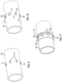
- the collars 46 may initially be in an expanded configuration, as illustrated in Figure 6 .
- the extremities 44 are plastically deformed in a radially inward direction to reduce their diameters.
- the extremities 44 may be crimped so the collars 46 plastically deform in a radially inward direction until a desired reduction in diameter occurs.
- the plastic deformation is applied sufficiently to squeeze the pads 60 between the base pipe 36 and the corresponding collars 46, as illustrated in Figure 7 .
- a retention member 72 e.g.
- a spring or a split ring may be used to initially maintain the pads 60 in their corresponding recesses 62 prior to the plastic deformation.
- the pads 60 may be glued or otherwise suitably maintained in their recesses 62.
- additional recesses 74 also may be formed in base pipe 36 as illustrated in Figure 9 .
- the additional recesses 74 are sized and located for receiving pads 60, as illustrated in Figure 10 .
- the pads 60 may initially be located on base pipe 36 and then the corresponding extremity 44 may be slid over the pads 60 as illustrated in Figure 11 .
- the collar 46 of the corresponding extremity 44 may then be crimped or otherwise plastically deformed to secure the pads 60 between the extremity 44 and the base pipe 36.
- a suitable retention member 72 may be used to initially secure pads 60 in the additional recesses 74 formed along base pipe 36.
- the anchoring system 48 comprises a plurality of wedge members 76 which are arranged between the collar 46 and the base pipe 36 at one or both of the extremities 44.
- the wedge members 76 may be arranged in a helical pattern between each extremity 44 and the base pipe 36.
- each wedge member 76 may have a generally helicoidal shape and may be oriented helically about the interior of the corresponding collar 46. Because of the helical orientation, the wedge members 76 serve as both axial mechanism 50 and rotational mechanism 52 to prevent relative movement of the packer 34 with respect to the base pipe 36 in both an axial direction and a rotational direction.
- each wedge member 76 may have a cross-sectional shape with a hump or curved portion 78 received in a corresponding recess 80 formed in the interior surface of the corresponding collar 46. Additionally, the interior of each wedge member 76 may comprise gripping features 82 oriented to grip into base pipe 36 once the collar 46 is suitably plastically deformed in a radially inward direction. Similar to other embodiments described herein, the wedge members 76 create an interference between the base pipe 36 and the packer 34. However, the orientation of wedge members 76 serve to create interference in both axial and rotational directions.
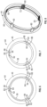
- the anchoring system 48 comprises an annular ring 84, e.g. a split annular ring, having a cross-sectional cone shape (or other suitable shape) to create a cone shaped portion 86 received in a corresponding recess 88.
- the corresponding recess 88 may be formed in the interior surface of the corresponding collar 46 along a portion of the circumference of the interior surface.
- the interior of annular ring 84 may comprise gripping features 90 oriented to grip into base pipe 36 once the collar 46 is suitably plastically deformed in a radially inward direction.
- the annular ring 84 may extend circumferentially along the corresponding recess 88, e.g. groove, formed along a portion of the interior of the corresponding collar 46.
- the annular ring 84 also comprises ends 92.
- the ring ends 92 are located adjacent interference portions 94 of collar 46 at the ends of recess 88 to prevent movement of annular ring 84 along the recess/groove 88 (see Figure 14 ).
- the gripping features 90 engage base pipe 36 and cooperate with the cone shaped portion 86 to prevent sliding axial movement of the packer 34 with respect to the base pipe 36.
- some embodiments may route hydraulic lines 95 between ends 92, e.g. hydraulic lines for connecting the packer body to an expansion valve system.
- the ring ends 92 of split annular ring 84 prevent relative rotation of the packer 34 with respect to the base pipe 36 via interfering engagement with interference members 94 (as the base pipe 36 is gripped via gripping features 90).
- the annular ring 84 serves as both the axial mechanism 50 and rotational mechanism 52.
- anchoring system 48 comprises a waved annular ring 96 having a cross-sectional shape with a hump or curved portion 98 received in a corresponding recess 100 formed in the interior surface of the corresponding collar 46.
- the sides of the waved annular ring 96 are shaped in an undulating or waved pattern such that the ring 96 has axially wide sections 102 and axially narrow sections 104.
- the size of the hump or curved section 98 is thus greater in the axially wide sections 102 and smaller in the axially narrow sections 104.
- the corresponding recess 100 may be formed with a similar or matching waved pattern.
- waved annular ring 96 may comprise gripping features 106 oriented to grip into base pipe 36 once the collar 46 is suitably plastically deformed in a radially inward direction.
- the waved annular ring 96 may extend circumferentially along the corresponding recess 100 formed in the interior of the corresponding collar 46.
- the waved annular ring 96 may extend circumferentially along a portion of the interior of the corresponding collar 46 between ring ends 108, as illustrated in Figure 16 .
- the gripping features 106 engage base pipe 36 and cooperate with the hump or curved portion 98 to prevent sliding axial movement of the packer 34 with respect to the base pipe 36.
- the gripping features 106 and the larger humps of axially wide sections 102 prevent relative rotation of the packer 34 with respect to the base pipe 36.
- the larger humps of axially wide sections 102 create an interfering engagement with the corresponding collar 46 to prevent rotation of the collar 46 (thus preventing rotation of the packer 34) with respect to the base pipe 36.
- the waved annular ring 96 effectively serves as the axial mechanism 50 and the rotational mechanism 52.
- FIG. 17 another embodiment of anchoring system 48 is illustrated.
- the axial mechanism 50 and rotational mechanism 52 are again combined in the form of a plurality of dome-shaped members 110 disposed between the collar 46 and the base pipe 36.
- the plurality of dome-shaped members 110 may be positioned within corresponding dome recesses 112 formed in collar 46 of the corresponding extremity 44.
- the dome-shaped members 110 each have a gripping side with rotational gripping features 114 oriented toward base pipe 36 for engagement with base pipe 36 when the corresponding collar 46 is plastically deformed in an inward direction.
- Each dome-shaped member 110 also has a curved side 116, e.g. domed side, disposed in the corresponding recess 112 and oriented against the corresponding collar 46/extremity 44. Placement of dome-shaped members 110 in corresponding recesses 112 effectively creates interference between the base pipe 36 and the collar 46/packer 34 in both an axial direction and a rotational direction.
- a retention member 118 e.g. a spring or a split ring, may be used to initially maintain the dome-shaped members 110 in their corresponding recesses 112 prior to the plastic deformation.
- each dome-shaped member 110 engage base pipe 36 and cooperate with the domed side 116 to prevent sliding axial movement of the packer 34 with respect to the base pipe 36. Furthermore, once the collar 46 is suitably plastically deformed in the radially inward direction, the gripping features 114 and the domed side 116 also prevent relative rotation of the packer 34 with respect to the base pipe 36. In other words, the dome-shaped members 110 create an interfering engagement with the corresponding collar 46 to prevent rotation of the collar 46 and overall packer 34 with respect to the base pipe 36. In this manner, the dome-shaped members 110 serve as both the axial mechanism 50 and the rotational mechanism 52.
- the well system 30 may have many types of configurations.
- the well system 30 may utilize tubing string 38 in the form of a casing while drilling string or other suitable tubing string used in high torque load applications.
- the expandable metal packer 34 may be employed as an isolation device in a variety of operations and environments which may be subjected to high differential pressures.
- the expandable metal packer 34 may be used in well applications and in other applications in which isolation between sections of a tubular structure is desired.
- the expandable metal packer 34 may be constructed with various types and sizes of expandable metal sleeves 40 depending on the parameters of a given operation.
- the expandable metal sleeve 40 may be formed from a plastically deformable metal membrane, bladder, or other metal structure which may be radially expanded via fluid pressure.
- the anchoring system 48 may have various configurations and may be located between one of the extremities 44 and the base pipe 36 or between both extremities 44 and the base pipe 36. Additionally, the expandable metal sleeve 40 may be secured to extremities 44 via a variety of techniques, including threaded engagement, welding, combined seals and fasteners, crimping, and/or other suitable coupling techniques. The anchoring system 48 also may utilize features of various sizes and configurations to create interference between the packer 34 and the base pipe 36 so as to prevent relative rotation of the packer 34 with respect to the base pipe 36.
Landscapes
- Life Sciences & Earth Sciences (AREA)
- Engineering & Computer Science (AREA)
- Geology (AREA)
- Mining & Mineral Resources (AREA)
- Physics & Mathematics (AREA)
- Environmental & Geological Engineering (AREA)
- Fluid Mechanics (AREA)
- General Life Sciences & Earth Sciences (AREA)
- Geochemistry & Mineralogy (AREA)
- Piles And Underground Anchors (AREA)
Claims (13)
- System zur Verwendung in einer Bohrung, umfassend:einen Rohrstrang (38), der ein Basisrohr (36) aufweist,einen erweiterbaren Metallpacker (34), der um das Basisrohr (36) herum montiert ist und eine erweiterbare Metallhülse (40) aufweist, die entlang des Basisrohrs (36) über ein Paar von Endpunkten (44) und ein Verankerungssystem (48) betriebsmäßig verankert ist, wobei das Verankerungssystem (48) zwischen mindestens einem der Endpunkte (44) und dem Basisrohr (36) positioniert ist und ein oder mehrere Merkmale einschließt, um eine Interferenz zwischen dem erweiterbaren Metallpacker (34) und dem Basisrohr (36) zu erzeugen, um ein axiales Gleiten des erweiterbaren Metallpackers (34) in Bezug auf das Basisrohr (36) zu verhindern und eine Drehbewegung des erweiterbaren Metallpackers (34) in Bezug auf das Basisrohr (36) zu verhindern.
- System nach Anspruch 1, wobei das Verankerungssystem (48) zwischen jedem der Endpunkte (44) und dem Basisrohr (36) positioniert ist.
- System nach Anspruch 1, wobei jeder Endpunkt (44) gegen das Basisrohr (36) verpresst ist.
- System nach Anspruch 1, wobei das eine oder die mehreren Merkmale des Verankerungssystems (48) einen kreisförmigen Ring (54) umfassen, der positioniert ist, um eine Interferenz zwischen dem Basisrohr (36) und einem entsprechenden Endpunkt (44) des Paars von Endpunkten zu erzeugen, um eine axiale Bewegung des erweiterbaren Metallpackers (34) in Bezug auf das Basisrohr (36) zu verhindern.
- System nach Anspruch 1, wobei das eine oder die mehreren Merkmale des Verankerungssystems (48) ein Pad (60) umfasst, das eine Greifseite (64), die gegen das Basisrohr (36) ausgerichtet ist, und eine gekrümmte Seite (66) aufweist, die gegen den entsprechenden Endpunkt (44) ausgerichtet ist, um über einen Keileffekt eine Interferenz zu erzeugen und so eine Drehbewegung des erweiterbaren Metallpackers (34) in Bezug auf das Basisrohr (36) zu verhindern.
- System nach Anspruch 5, wobei das Pad eine Vielzahl von Pads (60) umfasst, die zwischen jedem Endpunkt (44) und dem Basisrohr (36) montiert sind.
- System nach Anspruch 1, wobei das eine oder die mehreren Merkmale des Verankerungssystems (48) eine Vielzahl von Keilelementen (76) umfassen, die in einem spiralförmigen Muster zwischen den Endpunkten (44) und dem Basisrohr (36) angeordnet sind.
- System nach Anspruch 1, wobei das eine oder die mehreren Merkmale des Verankerungssystems (48) einen geteilten kreisförmigen Ring (84) umfassen, der beabstandete Umfangsenden (92) aufweist, die in entsprechende Merkmale (88) eingreifen, um eine relative Drehung des Packers (34) in Bezug auf das Basisrohr (36) zu verhindern.
- System nach Anspruch 1, wobei das eine oder die mehreren Merkmale des Verankerungssystems (48) einen gewellten kreisförmigen Ring (96) umfassen, der gewellte Abschnitte (102, 104) aufweist, die ausgerichtet sind, um eine Interferenz zu erzeugen und so eine Drehung des Packers (34) in Bezug auf das Basisrohr (36) zu verhindern.
- System nach Anspruch 1, wobei das eine oder die mehreren Merkmale des Verankerungssystems (48) eine Vielzahl von kuppelförmigen Elementen (110) umfassen, die zwischen den Endpunkten (44) und dem Basisrohr (36) positioniert sind, um eine Interferenz zu erzeugen, die eine relative Drehung des Packers (34) in Bezug auf das Basisrohr (34) verhindert.
- System nach Anspruch 1, wobei der Rohrstrang (38) einen Bohrstrang umfasst.
- Verfahren, umfassend:Bereitstellen eines Packers (34) mit einer erweiterbaren Metallhülse (40), die zwischen Endpunkten (44) positioniert ist;Positionieren des Packers (34) entlang eines Basisrohrs (36) eines Rohrstrangs (38);Sicherstellen einer geeigneten Platzierung eines Verankerungssystems (40) zwischen den Endpunkten (44) und dem Basisrohr (36), wobei das Verankerungssystem ein oder mehrere Merkmale einschließt, um eine Interferenz zwischen dem erweiterbaren Metallpacker (34) und dem Basisrohr (36) zu erzeugen, undplastisches Verformen der Endpunkte (44), um das Verankerungssystem (40) mit dem Basisrohr (36) und mit einer Innenseite der Endpunkte (44) in Eingriff zu bringen, wobei die Merkmale des Verankerungssystems konfiguriert sind, um eine Interferenz zwischen dem erweiterbaren Metallpacker (34) und dem Basisrohr (36) zu erzeugen, um eine axiale und Drehbewegung des Packers (34) in Bezug auf das Basisrohr (36) zu verhindern.
- Verfahren nach Anspruch 12, ferner umfassend ein Einsetzen des Packers (34) unter Tage in ein Bohrloch und das Erweitern der erweiterbaren Metallhülse (40), um einen dichtenden Eingriff mit einer umgebenden Bohrungswand (42) aufrechtzuerhalten.
Applications Claiming Priority (2)
| Application Number | Priority Date | Filing Date | Title |
|---|---|---|---|
| EP19305084 | 2019-01-23 | ||
| PCT/EP2020/051609 WO2020152260A1 (en) | 2019-01-23 | 2020-01-23 | Expandable metal packer with anchoring system |
Publications (2)
| Publication Number | Publication Date |
|---|---|
| EP3914802A1 EP3914802A1 (de) | 2021-12-01 |
| EP3914802B1 true EP3914802B1 (de) | 2025-07-02 |
Family
ID=65409012
Family Applications (1)
| Application Number | Title | Priority Date | Filing Date |
|---|---|---|---|
| EP20701464.8A Active EP3914802B1 (de) | 2019-01-23 | 2020-01-23 | Expandierbarer metallpacker mit verankerungssystem |
Country Status (3)
| Country | Link |
|---|---|
| US (1) | US11802455B2 (de) |
| EP (1) | EP3914802B1 (de) |
| WO (1) | WO2020152260A1 (de) |
Families Citing this family (1)
| Publication number | Priority date | Publication date | Assignee | Title |
|---|---|---|---|---|
| CN112780221B (zh) * | 2021-03-03 | 2021-11-02 | 东营市友佳石油科技有限公司 | 储层无污染免射孔固井工具装置及方法 |
Citations (1)
| Publication number | Priority date | Publication date | Assignee | Title |
|---|---|---|---|---|
| EP2206879B1 (de) * | 2009-01-12 | 2014-02-26 | Welltec A/S | Ringförmige Sperre und ringförmiges Absperrungssystem |
Family Cites Families (13)
| Publication number | Priority date | Publication date | Assignee | Title |
|---|---|---|---|---|
| US20060042801A1 (en) | 2004-08-24 | 2006-03-02 | Hackworth Matthew R | Isolation device and method |
| EP2625375B1 (de) | 2010-10-07 | 2017-04-12 | Welltec A/S | Ringförmige barriere |
| EP2565368A1 (de) * | 2011-08-31 | 2013-03-06 | Welltec A/S | Ringförmige Absperrung mit Druckverstärkung |
| EP2570587B1 (de) * | 2011-09-13 | 2013-10-30 | Welltec A/S | Ringförmige Sperre mit Sicherheitsmetallhülle |
| FR2989412B1 (fr) * | 2012-04-13 | 2015-03-13 | Saltel Ind | Conduite pourvue d'un element metallique serti |
| US9109417B2 (en) | 2012-06-27 | 2015-08-18 | Odfjell Well Services Europe As | Drill string mountable wellbore cleanup apparatus and method |
| EP2853681A1 (de) * | 2013-09-30 | 2015-04-01 | Welltec A/S | Wärmeexpandierte ringförmige Barriere |
| EP2947259A1 (de) * | 2014-05-19 | 2015-11-25 | Welltec A/S | Bohrlochstrang zum Bohren durch eine Unterdruckzone |
| GB201417671D0 (en) | 2014-10-07 | 2014-11-19 | Meta Downhole Ltd | Improved isolation barrier |
| EP3061901A1 (de) | 2015-02-27 | 2016-08-31 | Saltel Industries | Vorrichtung zum brechen oder erneuten brechen eines bohrlochs und zugehöriges herstellungsverfahren |
| EP3263829A1 (de) * | 2016-06-28 | 2018-01-03 | Welltec A/S | Bohrlochbohrsystem |
| US20200165892A1 (en) * | 2018-11-23 | 2020-05-28 | Welltec Oilfield Solutions Ag | Annular barrier |
| EP3690183A1 (de) * | 2019-01-31 | 2020-08-05 | Welltec Oilfield Solutions AG | Ringförmige barriere mit ventilsystem |
-
2020
- 2020-01-23 WO PCT/EP2020/051609 patent/WO2020152260A1/en not_active Ceased
- 2020-01-23 US US17/423,288 patent/US11802455B2/en active Active
- 2020-01-23 EP EP20701464.8A patent/EP3914802B1/de active Active
Patent Citations (1)
| Publication number | Priority date | Publication date | Assignee | Title |
|---|---|---|---|---|
| EP2206879B1 (de) * | 2009-01-12 | 2014-02-26 | Welltec A/S | Ringförmige Sperre und ringförmiges Absperrungssystem |
Also Published As
| Publication number | Publication date |
|---|---|
| EP3914802A1 (de) | 2021-12-01 |
| WO2020152260A1 (en) | 2020-07-30 |
| US11802455B2 (en) | 2023-10-31 |
| US20220090459A1 (en) | 2022-03-24 |
Similar Documents
| Publication | Publication Date | Title |
|---|---|---|
| US7938192B2 (en) | Packer | |
| US9217308B2 (en) | Active external casing packer (ECP) for frac operations in oil and gas wells | |
| US7845402B2 (en) | Expandable packer system | |
| US6827150B2 (en) | High expansion packer | |
| US7306033B2 (en) | Apparatus for isolating zones in a well | |
| US11525327B2 (en) | Morphable apparatus | |
| US8714273B2 (en) | High expansion metal seal system | |
| US11136854B2 (en) | Downhole tool with sealing ring | |
| US12392212B2 (en) | Annular barrier | |
| US9567837B2 (en) | Tubular connection | |
| WO2012059469A2 (en) | Expandable packer | |
| US12392227B2 (en) | System and methodology for utilizing anchoring element with expandable tubular | |
| US20240084667A1 (en) | Slip system for use in downhole applications | |
| CN107075932B (zh) | 改进的隔离屏障 | |
| US11802455B2 (en) | Expandable metal packer with anchoring system | |
| AU2020306680B2 (en) | Annular barrier with press connections | |
| AU2020295720B2 (en) | Annular barrier with bite connection | |
| CN221503249U (zh) | 一种金属密封尾管悬挂器 | |
| WO2024233872A1 (en) | Expandable tubular system with double sleeve | |
| US20150191989A1 (en) | Sealing apparatus and method |
Legal Events
| Date | Code | Title | Description |
|---|---|---|---|
| STAA | Information on the status of an ep patent application or granted ep patent |
Free format text: STATUS: UNKNOWN |
|
| STAA | Information on the status of an ep patent application or granted ep patent |
Free format text: STATUS: THE INTERNATIONAL PUBLICATION HAS BEEN MADE |
|
| PUAI | Public reference made under article 153(3) epc to a published international application that has entered the european phase |
Free format text: ORIGINAL CODE: 0009012 |
|
| STAA | Information on the status of an ep patent application or granted ep patent |
Free format text: STATUS: REQUEST FOR EXAMINATION WAS MADE |
|
| 17P | Request for examination filed |
Effective date: 20210721 |
|
| AK | Designated contracting states |
Kind code of ref document: A1 Designated state(s): AL AT BE BG CH CY CZ DE DK EE ES FI FR GB GR HR HU IE IS IT LI LT LU LV MC MK MT NL NO PL PT RO RS SE SI SK SM TR |
|
| DAV | Request for validation of the european patent (deleted) | ||
| DAX | Request for extension of the european patent (deleted) | ||
| STAA | Information on the status of an ep patent application or granted ep patent |
Free format text: STATUS: EXAMINATION IS IN PROGRESS |
|
| 17Q | First examination report despatched |
Effective date: 20220727 |
|
| GRAP | Despatch of communication of intention to grant a patent |
Free format text: ORIGINAL CODE: EPIDOSNIGR1 |
|
| STAA | Information on the status of an ep patent application or granted ep patent |
Free format text: STATUS: GRANT OF PATENT IS INTENDED |
|
| INTG | Intention to grant announced |
Effective date: 20250207 |
|
| GRAS | Grant fee paid |
Free format text: ORIGINAL CODE: EPIDOSNIGR3 |
|
| GRAA | (expected) grant |
Free format text: ORIGINAL CODE: 0009210 |
|
| STAA | Information on the status of an ep patent application or granted ep patent |
Free format text: STATUS: THE PATENT HAS BEEN GRANTED |
|
| AK | Designated contracting states |
Kind code of ref document: B1 Designated state(s): AL AT BE BG CH CY CZ DE DK EE ES FI FR GB GR HR HU IE IS IT LI LT LU LV MC MK MT NL NO PL PT RO RS SE SI SK SM TR |
|
| REG | Reference to a national code |
Ref country code: GB Ref legal event code: FG4D |
|
| REG | Reference to a national code |
Ref country code: CH Ref legal event code: EP |
|
| REG | Reference to a national code |
Ref country code: DE Ref legal event code: R096 Ref document number: 602020053734 Country of ref document: DE |
|
| REG | Reference to a national code |
Ref country code: IE Ref legal event code: FG4D |
|
| REG | Reference to a national code |
Ref country code: NL Ref legal event code: MP Effective date: 20250702 |
|
| PG25 | Lapsed in a contracting state [announced via postgrant information from national office to epo] |
Ref country code: PT Free format text: LAPSE BECAUSE OF FAILURE TO SUBMIT A TRANSLATION OF THE DESCRIPTION OR TO PAY THE FEE WITHIN THE PRESCRIBED TIME-LIMIT Effective date: 20251103 |
|
| PG25 | Lapsed in a contracting state [announced via postgrant information from national office to epo] |
Ref country code: NL Free format text: LAPSE BECAUSE OF FAILURE TO SUBMIT A TRANSLATION OF THE DESCRIPTION OR TO PAY THE FEE WITHIN THE PRESCRIBED TIME-LIMIT Effective date: 20250702 |
|
| REG | Reference to a national code |
Ref country code: AT Ref legal event code: MK05 Ref document number: 1809440 Country of ref document: AT Kind code of ref document: T Effective date: 20250702 |
|
| PG25 | Lapsed in a contracting state [announced via postgrant information from national office to epo] |
Ref country code: IS Free format text: LAPSE BECAUSE OF FAILURE TO SUBMIT A TRANSLATION OF THE DESCRIPTION OR TO PAY THE FEE WITHIN THE PRESCRIBED TIME-LIMIT Effective date: 20251102 |
|
| PGFP | Annual fee paid to national office [announced via postgrant information from national office to epo] |
Ref country code: NO Payment date: 20251021 Year of fee payment: 7 |
|
| REG | Reference to a national code |
Ref country code: LT Ref legal event code: MG9D |
|
| PG25 | Lapsed in a contracting state [announced via postgrant information from national office to epo] |
Ref country code: AT Free format text: LAPSE BECAUSE OF FAILURE TO SUBMIT A TRANSLATION OF THE DESCRIPTION OR TO PAY THE FEE WITHIN THE PRESCRIBED TIME-LIMIT Effective date: 20250702 |
|
| PG25 | Lapsed in a contracting state [announced via postgrant information from national office to epo] |
Ref country code: FI Free format text: LAPSE BECAUSE OF FAILURE TO SUBMIT A TRANSLATION OF THE DESCRIPTION OR TO PAY THE FEE WITHIN THE PRESCRIBED TIME-LIMIT Effective date: 20250702 |
|
| PG25 | Lapsed in a contracting state [announced via postgrant information from national office to epo] |
Ref country code: HR Free format text: LAPSE BECAUSE OF FAILURE TO SUBMIT A TRANSLATION OF THE DESCRIPTION OR TO PAY THE FEE WITHIN THE PRESCRIBED TIME-LIMIT Effective date: 20250702 |
|
| PGFP | Annual fee paid to national office [announced via postgrant information from national office to epo] |
Ref country code: FR Payment date: 20251031 Year of fee payment: 7 |
|
| PG25 | Lapsed in a contracting state [announced via postgrant information from national office to epo] |
Ref country code: GR Free format text: LAPSE BECAUSE OF FAILURE TO SUBMIT A TRANSLATION OF THE DESCRIPTION OR TO PAY THE FEE WITHIN THE PRESCRIBED TIME-LIMIT Effective date: 20251003 |
|
| PG25 | Lapsed in a contracting state [announced via postgrant information from national office to epo] |
Ref country code: SE Free format text: LAPSE BECAUSE OF FAILURE TO SUBMIT A TRANSLATION OF THE DESCRIPTION OR TO PAY THE FEE WITHIN THE PRESCRIBED TIME-LIMIT Effective date: 20250702 Ref country code: CZ Free format text: LAPSE BECAUSE OF FAILURE TO SUBMIT A TRANSLATION OF THE DESCRIPTION OR TO PAY THE FEE WITHIN THE PRESCRIBED TIME-LIMIT Effective date: 20250702 |
|
| PG25 | Lapsed in a contracting state [announced via postgrant information from national office to epo] |
Ref country code: LV Free format text: LAPSE BECAUSE OF FAILURE TO SUBMIT A TRANSLATION OF THE DESCRIPTION OR TO PAY THE FEE WITHIN THE PRESCRIBED TIME-LIMIT Effective date: 20250702 |
|
| PG25 | Lapsed in a contracting state [announced via postgrant information from national office to epo] |
Ref country code: BG Free format text: LAPSE BECAUSE OF FAILURE TO SUBMIT A TRANSLATION OF THE DESCRIPTION OR TO PAY THE FEE WITHIN THE PRESCRIBED TIME-LIMIT Effective date: 20250702 Ref country code: PL Free format text: LAPSE BECAUSE OF FAILURE TO SUBMIT A TRANSLATION OF THE DESCRIPTION OR TO PAY THE FEE WITHIN THE PRESCRIBED TIME-LIMIT Effective date: 20250702 |
|
| PG25 | Lapsed in a contracting state [announced via postgrant information from national office to epo] |
Ref country code: RS Free format text: LAPSE BECAUSE OF FAILURE TO SUBMIT A TRANSLATION OF THE DESCRIPTION OR TO PAY THE FEE WITHIN THE PRESCRIBED TIME-LIMIT Effective date: 20251002 |
|
| PG25 | Lapsed in a contracting state [announced via postgrant information from national office to epo] |
Ref country code: ES Free format text: LAPSE BECAUSE OF FAILURE TO SUBMIT A TRANSLATION OF THE DESCRIPTION OR TO PAY THE FEE WITHIN THE PRESCRIBED TIME-LIMIT Effective date: 20250702 |
|
| PG25 | Lapsed in a contracting state [announced via postgrant information from national office to epo] |
Ref country code: SM Free format text: LAPSE BECAUSE OF FAILURE TO SUBMIT A TRANSLATION OF THE DESCRIPTION OR TO PAY THE FEE WITHIN THE PRESCRIBED TIME-LIMIT Effective date: 20250702 |
|
| PG25 | Lapsed in a contracting state [announced via postgrant information from national office to epo] |
Ref country code: DK Free format text: LAPSE BECAUSE OF FAILURE TO SUBMIT A TRANSLATION OF THE DESCRIPTION OR TO PAY THE FEE WITHIN THE PRESCRIBED TIME-LIMIT Effective date: 20250702 |
|
| PG25 | Lapsed in a contracting state [announced via postgrant information from national office to epo] |
Ref country code: IT Free format text: LAPSE BECAUSE OF FAILURE TO SUBMIT A TRANSLATION OF THE DESCRIPTION OR TO PAY THE FEE WITHIN THE PRESCRIBED TIME-LIMIT Effective date: 20250702 |
|
| PG25 | Lapsed in a contracting state [announced via postgrant information from national office to epo] |
Ref country code: EE Free format text: LAPSE BECAUSE OF FAILURE TO SUBMIT A TRANSLATION OF THE DESCRIPTION OR TO PAY THE FEE WITHIN THE PRESCRIBED TIME-LIMIT Effective date: 20250702 Ref country code: SK Free format text: LAPSE BECAUSE OF FAILURE TO SUBMIT A TRANSLATION OF THE DESCRIPTION OR TO PAY THE FEE WITHIN THE PRESCRIBED TIME-LIMIT Effective date: 20250702 |
|
| PLBE | No opposition filed within time limit |
Free format text: ORIGINAL CODE: 0009261 |
|
| STAA | Information on the status of an ep patent application or granted ep patent |
Free format text: STATUS: NO OPPOSITION FILED WITHIN TIME LIMIT |