EP3914848B1 - Processus et procédé de transport d'hydrocarbure liquide et de co2 pour la production d'hydrogène avec capture de co2 - Google Patents
Processus et procédé de transport d'hydrocarbure liquide et de co2 pour la production d'hydrogène avec capture de co2 Download PDFInfo
- Publication number
- EP3914848B1 EP3914848B1 EP20714724.0A EP20714724A EP3914848B1 EP 3914848 B1 EP3914848 B1 EP 3914848B1 EP 20714724 A EP20714724 A EP 20714724A EP 3914848 B1 EP3914848 B1 EP 3914848B1
- Authority
- EP
- European Patent Office
- Prior art keywords
- lpg
- unit
- loading
- stream
- vessel
- Prior art date
- Legal status (The legal status is an assumption and is not a legal conclusion. Google has not performed a legal analysis and makes no representation as to the accuracy of the status listed.)
- Active
Links
Images






Classifications
-
- F—MECHANICAL ENGINEERING; LIGHTING; HEATING; WEAPONS; BLASTING
- F17—STORING OR DISTRIBUTING GASES OR LIQUIDS
- F17C—VESSELS FOR CONTAINING OR STORING COMPRESSED, LIQUEFIED OR SOLIDIFIED GASES; FIXED-CAPACITY GAS-HOLDERS; FILLING VESSELS WITH, OR DISCHARGING FROM VESSELS, COMPRESSED, LIQUEFIED, OR SOLIDIFIED GASES
- F17C7/00—Methods or apparatus for discharging liquefied, solidified, or compressed gases from pressure vessels, not covered by another subclass
- F17C7/02—Discharging liquefied gases
- F17C7/04—Discharging liquefied gases with change of state, e.g. vaporisation
-
- F—MECHANICAL ENGINEERING; LIGHTING; HEATING; WEAPONS; BLASTING
- F17—STORING OR DISTRIBUTING GASES OR LIQUIDS
- F17C—VESSELS FOR CONTAINING OR STORING COMPRESSED, LIQUEFIED OR SOLIDIFIED GASES; FIXED-CAPACITY GAS-HOLDERS; FILLING VESSELS WITH, OR DISCHARGING FROM VESSELS, COMPRESSED, LIQUEFIED, OR SOLIDIFIED GASES
- F17C5/00—Methods or apparatus for filling containers with liquefied, solidified, or compressed gases under pressures
-
- B—PERFORMING OPERATIONS; TRANSPORTING
- B01—PHYSICAL OR CHEMICAL PROCESSES OR APPARATUS IN GENERAL
- B01J—CHEMICAL OR PHYSICAL PROCESSES, e.g. CATALYSIS OR COLLOID CHEMISTRY; THEIR RELEVANT APPARATUS
- B01J7/00—Apparatus for generating gases
-
- C—CHEMISTRY; METALLURGY
- C01—INORGANIC CHEMISTRY
- C01B—NON-METALLIC ELEMENTS; COMPOUNDS THEREOF; METALLOIDS OR COMPOUNDS THEREOF NOT COVERED BY SUBCLASS C01C
- C01B3/00—Hydrogen; Gaseous mixtures containing hydrogen; Separation of hydrogen from mixtures containing it; Purification of hydrogen; Reversible storage of hydrogen
- C01B3/02—Production of hydrogen; Production of gaseous mixtures containing hydrogen
- C01B3/32—Production of hydrogen; Production of gaseous mixtures containing hydrogen by reaction of gaseous or liquid organic compounds with gasifying agents, e.g. water, carbon dioxide or air
- C01B3/34—Production of hydrogen; Production of gaseous mixtures containing hydrogen by reaction of gaseous or liquid organic compounds with gasifying agents, e.g. water, carbon dioxide or air by reaction of hydrocarbons with gasifying agents
-
- F—MECHANICAL ENGINEERING; LIGHTING; HEATING; WEAPONS; BLASTING
- F17—STORING OR DISTRIBUTING GASES OR LIQUIDS
- F17C—VESSELS FOR CONTAINING OR STORING COMPRESSED, LIQUEFIED OR SOLIDIFIED GASES; FIXED-CAPACITY GAS-HOLDERS; FILLING VESSELS WITH, OR DISCHARGING FROM VESSELS, COMPRESSED, LIQUEFIED, OR SOLIDIFIED GASES
- F17C7/00—Methods or apparatus for discharging liquefied, solidified, or compressed gases from pressure vessels, not covered by another subclass
- F17C7/02—Discharging liquefied gases
-
- F—MECHANICAL ENGINEERING; LIGHTING; HEATING; WEAPONS; BLASTING
- F25—REFRIGERATION OR COOLING; COMBINED HEATING AND REFRIGERATION SYSTEMS; HEAT PUMP SYSTEMS; MANUFACTURE OR STORAGE OF ICE; LIQUEFACTION SOLIDIFICATION OF GASES
- F25J—LIQUEFACTION, SOLIDIFICATION OR SEPARATION OF GASES OR GASEOUS OR LIQUEFIED GASEOUS MIXTURES BY PRESSURE AND COLD TREATMENT OR BY BRINGING THEM INTO THE SUPERCRITICAL STATE
- F25J3/00—Processes or apparatus for separating the constituents of gaseous or liquefied gaseous mixtures involving the use of liquefaction or solidification
- F25J3/02—Processes or apparatus for separating the constituents of gaseous or liquefied gaseous mixtures involving the use of liquefaction or solidification by rectification, i.e. by continuous interchange of heat and material between a vapour stream and a liquid stream
- F25J3/0228—Processes or apparatus for separating the constituents of gaseous or liquefied gaseous mixtures involving the use of liquefaction or solidification by rectification, i.e. by continuous interchange of heat and material between a vapour stream and a liquid stream characterised by the separated product stream
- F25J3/0266—Processes or apparatus for separating the constituents of gaseous or liquefied gaseous mixtures involving the use of liquefaction or solidification by rectification, i.e. by continuous interchange of heat and material between a vapour stream and a liquid stream characterised by the separated product stream separation of carbon dioxide
-
- F—MECHANICAL ENGINEERING; LIGHTING; HEATING; WEAPONS; BLASTING
- F25—REFRIGERATION OR COOLING; COMBINED HEATING AND REFRIGERATION SYSTEMS; HEAT PUMP SYSTEMS; MANUFACTURE OR STORAGE OF ICE; LIQUEFACTION SOLIDIFICATION OF GASES
- F25J—LIQUEFACTION, SOLIDIFICATION OR SEPARATION OF GASES OR GASEOUS OR LIQUEFIED GASEOUS MIXTURES BY PRESSURE AND COLD TREATMENT OR BY BRINGING THEM INTO THE SUPERCRITICAL STATE
- F25J3/00—Processes or apparatus for separating the constituents of gaseous or liquefied gaseous mixtures involving the use of liquefaction or solidification
- F25J3/02—Processes or apparatus for separating the constituents of gaseous or liquefied gaseous mixtures involving the use of liquefaction or solidification by rectification, i.e. by continuous interchange of heat and material between a vapour stream and a liquid stream
- F25J3/0295—Start-up or control of the process; Details of the apparatus used, e.g. sieve plates, packings
-
- C—CHEMISTRY; METALLURGY
- C01—INORGANIC CHEMISTRY
- C01B—NON-METALLIC ELEMENTS; COMPOUNDS THEREOF; METALLOIDS OR COMPOUNDS THEREOF NOT COVERED BY SUBCLASS C01C
- C01B2203/00—Integrated processes for the production of hydrogen or synthesis gas
- C01B2203/12—Feeding the process for making hydrogen or synthesis gas
- C01B2203/1205—Composition of the feed
- C01B2203/1211—Organic compounds or organic mixtures used in the process for making hydrogen or synthesis gas
- C01B2203/1235—Hydrocarbons
- C01B2203/1247—Higher hydrocarbons
-
- F—MECHANICAL ENGINEERING; LIGHTING; HEATING; WEAPONS; BLASTING
- F17—STORING OR DISTRIBUTING GASES OR LIQUIDS
- F17C—VESSELS FOR CONTAINING OR STORING COMPRESSED, LIQUEFIED OR SOLIDIFIED GASES; FIXED-CAPACITY GAS-HOLDERS; FILLING VESSELS WITH, OR DISCHARGING FROM VESSELS, COMPRESSED, LIQUEFIED, OR SOLIDIFIED GASES
- F17C2221/00—Handled fluid, in particular type of fluid
- F17C2221/01—Pure fluids
- F17C2221/012—Hydrogen
-
- F—MECHANICAL ENGINEERING; LIGHTING; HEATING; WEAPONS; BLASTING
- F17—STORING OR DISTRIBUTING GASES OR LIQUIDS
- F17C—VESSELS FOR CONTAINING OR STORING COMPRESSED, LIQUEFIED OR SOLIDIFIED GASES; FIXED-CAPACITY GAS-HOLDERS; FILLING VESSELS WITH, OR DISCHARGING FROM VESSELS, COMPRESSED, LIQUEFIED, OR SOLIDIFIED GASES
- F17C2221/00—Handled fluid, in particular type of fluid
- F17C2221/01—Pure fluids
- F17C2221/013—Carbon dioxide
-
- F—MECHANICAL ENGINEERING; LIGHTING; HEATING; WEAPONS; BLASTING
- F17—STORING OR DISTRIBUTING GASES OR LIQUIDS
- F17C—VESSELS FOR CONTAINING OR STORING COMPRESSED, LIQUEFIED OR SOLIDIFIED GASES; FIXED-CAPACITY GAS-HOLDERS; FILLING VESSELS WITH, OR DISCHARGING FROM VESSELS, COMPRESSED, LIQUEFIED, OR SOLIDIFIED GASES
- F17C2221/00—Handled fluid, in particular type of fluid
- F17C2221/03—Mixtures
- F17C2221/032—Hydrocarbons
- F17C2221/033—Methane, e.g. natural gas, CNG, LNG, GNL, GNC, PLNG
-
- F—MECHANICAL ENGINEERING; LIGHTING; HEATING; WEAPONS; BLASTING
- F17—STORING OR DISTRIBUTING GASES OR LIQUIDS
- F17C—VESSELS FOR CONTAINING OR STORING COMPRESSED, LIQUEFIED OR SOLIDIFIED GASES; FIXED-CAPACITY GAS-HOLDERS; FILLING VESSELS WITH, OR DISCHARGING FROM VESSELS, COMPRESSED, LIQUEFIED, OR SOLIDIFIED GASES
- F17C2221/00—Handled fluid, in particular type of fluid
- F17C2221/03—Mixtures
- F17C2221/032—Hydrocarbons
- F17C2221/035—Propane butane, e.g. LPG, GPL
-
- F—MECHANICAL ENGINEERING; LIGHTING; HEATING; WEAPONS; BLASTING
- F17—STORING OR DISTRIBUTING GASES OR LIQUIDS
- F17C—VESSELS FOR CONTAINING OR STORING COMPRESSED, LIQUEFIED OR SOLIDIFIED GASES; FIXED-CAPACITY GAS-HOLDERS; FILLING VESSELS WITH, OR DISCHARGING FROM VESSELS, COMPRESSED, LIQUEFIED, OR SOLIDIFIED GASES
- F17C2227/00—Transfer of fluids, i.e. method or means for transferring the fluid; Heat exchange with the fluid
- F17C2227/03—Heat exchange with the fluid
- F17C2227/0302—Heat exchange with the fluid by heating
- F17C2227/0309—Heat exchange with the fluid by heating using another fluid
-
- F—MECHANICAL ENGINEERING; LIGHTING; HEATING; WEAPONS; BLASTING
- F17—STORING OR DISTRIBUTING GASES OR LIQUIDS
- F17C—VESSELS FOR CONTAINING OR STORING COMPRESSED, LIQUEFIED OR SOLIDIFIED GASES; FIXED-CAPACITY GAS-HOLDERS; FILLING VESSELS WITH, OR DISCHARGING FROM VESSELS, COMPRESSED, LIQUEFIED, OR SOLIDIFIED GASES
- F17C2227/00—Transfer of fluids, i.e. method or means for transferring the fluid; Heat exchange with the fluid
- F17C2227/03—Heat exchange with the fluid
- F17C2227/0337—Heat exchange with the fluid by cooling
- F17C2227/0341—Heat exchange with the fluid by cooling using another fluid
- F17C2227/0355—Heat exchange with the fluid by cooling using another fluid in a closed loop
-
- F—MECHANICAL ENGINEERING; LIGHTING; HEATING; WEAPONS; BLASTING
- F17—STORING OR DISTRIBUTING GASES OR LIQUIDS
- F17C—VESSELS FOR CONTAINING OR STORING COMPRESSED, LIQUEFIED OR SOLIDIFIED GASES; FIXED-CAPACITY GAS-HOLDERS; FILLING VESSELS WITH, OR DISCHARGING FROM VESSELS, COMPRESSED, LIQUEFIED, OR SOLIDIFIED GASES
- F17C2265/00—Effects achieved by gas storage or gas handling
- F17C2265/03—Treating the boil-off
-
- F—MECHANICAL ENGINEERING; LIGHTING; HEATING; WEAPONS; BLASTING
- F17—STORING OR DISTRIBUTING GASES OR LIQUIDS
- F17C—VESSELS FOR CONTAINING OR STORING COMPRESSED, LIQUEFIED OR SOLIDIFIED GASES; FIXED-CAPACITY GAS-HOLDERS; FILLING VESSELS WITH, OR DISCHARGING FROM VESSELS, COMPRESSED, LIQUEFIED, OR SOLIDIFIED GASES
- F17C2270/00—Applications
- F17C2270/01—Applications for fluid transport or storage
- F17C2270/0102—Applications for fluid transport or storage on or in the water
- F17C2270/0105—Ships
-
- F—MECHANICAL ENGINEERING; LIGHTING; HEATING; WEAPONS; BLASTING
- F17—STORING OR DISTRIBUTING GASES OR LIQUIDS
- F17C—VESSELS FOR CONTAINING OR STORING COMPRESSED, LIQUEFIED OR SOLIDIFIED GASES; FIXED-CAPACITY GAS-HOLDERS; FILLING VESSELS WITH, OR DISCHARGING FROM VESSELS, COMPRESSED, LIQUEFIED, OR SOLIDIFIED GASES
- F17C2270/00—Applications
- F17C2270/01—Applications for fluid transport or storage
- F17C2270/0102—Applications for fluid transport or storage on or in the water
- F17C2270/0118—Offshore
- F17C2270/0123—Terminals
-
- F—MECHANICAL ENGINEERING; LIGHTING; HEATING; WEAPONS; BLASTING
- F17—STORING OR DISTRIBUTING GASES OR LIQUIDS
- F17C—VESSELS FOR CONTAINING OR STORING COMPRESSED, LIQUEFIED OR SOLIDIFIED GASES; FIXED-CAPACITY GAS-HOLDERS; FILLING VESSELS WITH, OR DISCHARGING FROM VESSELS, COMPRESSED, LIQUEFIED, OR SOLIDIFIED GASES
- F17C2270/00—Applications
- F17C2270/01—Applications for fluid transport or storage
- F17C2270/0134—Applications for fluid transport or storage placed above the ground
- F17C2270/0136—Terminals
-
- F—MECHANICAL ENGINEERING; LIGHTING; HEATING; WEAPONS; BLASTING
- F25—REFRIGERATION OR COOLING; COMBINED HEATING AND REFRIGERATION SYSTEMS; HEAT PUMP SYSTEMS; MANUFACTURE OR STORAGE OF ICE; LIQUEFACTION SOLIDIFICATION OF GASES
- F25J—LIQUEFACTION, SOLIDIFICATION OR SEPARATION OF GASES OR GASEOUS OR LIQUEFIED GASEOUS MIXTURES BY PRESSURE AND COLD TREATMENT OR BY BRINGING THEM INTO THE SUPERCRITICAL STATE
- F25J2210/00—Processes characterised by the type or other details of the feed stream
- F25J2210/80—Carbon dioxide
-
- F—MECHANICAL ENGINEERING; LIGHTING; HEATING; WEAPONS; BLASTING
- F25—REFRIGERATION OR COOLING; COMBINED HEATING AND REFRIGERATION SYSTEMS; HEAT PUMP SYSTEMS; MANUFACTURE OR STORAGE OF ICE; LIQUEFACTION SOLIDIFICATION OF GASES
- F25J—LIQUEFACTION, SOLIDIFICATION OR SEPARATION OF GASES OR GASEOUS OR LIQUEFIED GASEOUS MIXTURES BY PRESSURE AND COLD TREATMENT OR BY BRINGING THEM INTO THE SUPERCRITICAL STATE
- F25J2210/00—Processes characterised by the type or other details of the feed stream
- F25J2210/90—Boil-off gas from storage
-
- F—MECHANICAL ENGINEERING; LIGHTING; HEATING; WEAPONS; BLASTING
- F25—REFRIGERATION OR COOLING; COMBINED HEATING AND REFRIGERATION SYSTEMS; HEAT PUMP SYSTEMS; MANUFACTURE OR STORAGE OF ICE; LIQUEFACTION SOLIDIFICATION OF GASES
- F25J—LIQUEFACTION, SOLIDIFICATION OR SEPARATION OF GASES OR GASEOUS OR LIQUEFIED GASEOUS MIXTURES BY PRESSURE AND COLD TREATMENT OR BY BRINGING THEM INTO THE SUPERCRITICAL STATE
- F25J2290/00—Other details not covered by groups F25J2200/00 - F25J2280/00
- F25J2290/62—Details of storing a fluid in a tank
-
- Y—GENERAL TAGGING OF NEW TECHNOLOGICAL DEVELOPMENTS; GENERAL TAGGING OF CROSS-SECTIONAL TECHNOLOGIES SPANNING OVER SEVERAL SECTIONS OF THE IPC; TECHNICAL SUBJECTS COVERED BY FORMER USPC CROSS-REFERENCE ART COLLECTIONS [XRACs] AND DIGESTS
- Y02—TECHNOLOGIES OR APPLICATIONS FOR MITIGATION OR ADAPTATION AGAINST CLIMATE CHANGE
- Y02C—CAPTURE, STORAGE, SEQUESTRATION OR DISPOSAL OF GREENHOUSE GASES [GHG]
- Y02C20/00—Capture or disposal of greenhouse gases
- Y02C20/40—Capture or disposal of greenhouse gases of CO2
-
- Y—GENERAL TAGGING OF NEW TECHNOLOGICAL DEVELOPMENTS; GENERAL TAGGING OF CROSS-SECTIONAL TECHNOLOGIES SPANNING OVER SEVERAL SECTIONS OF THE IPC; TECHNICAL SUBJECTS COVERED BY FORMER USPC CROSS-REFERENCE ART COLLECTIONS [XRACs] AND DIGESTS
- Y02—TECHNOLOGIES OR APPLICATIONS FOR MITIGATION OR ADAPTATION AGAINST CLIMATE CHANGE
- Y02E—REDUCTION OF GREENHOUSE GAS [GHG] EMISSIONS, RELATED TO ENERGY GENERATION, TRANSMISSION OR DISTRIBUTION
- Y02E60/00—Enabling technologies; Technologies with a potential or indirect contribution to GHG emissions mitigation
- Y02E60/30—Hydrogen technology
- Y02E60/32—Hydrogen storage
-
- Y—GENERAL TAGGING OF NEW TECHNOLOGICAL DEVELOPMENTS; GENERAL TAGGING OF CROSS-SECTIONAL TECHNOLOGIES SPANNING OVER SEVERAL SECTIONS OF THE IPC; TECHNICAL SUBJECTS COVERED BY FORMER USPC CROSS-REFERENCE ART COLLECTIONS [XRACs] AND DIGESTS
- Y02—TECHNOLOGIES OR APPLICATIONS FOR MITIGATION OR ADAPTATION AGAINST CLIMATE CHANGE
- Y02P—CLIMATE CHANGE MITIGATION TECHNOLOGIES IN THE PRODUCTION OR PROCESSING OF GOODS
- Y02P30/00—Technologies relating to oil refining and petrochemical industry
Definitions
- the present invention relates generally to transport of fluids and more particularly to efficient and effective ways to transport CO 2 and hydrocarbons that reduce energy consumption and shipping costs.
- a loading and unloading station for simultaneous unloading of a first fluid from at least one storage tank in a vessel and loading of a second fluid into a storage tank of the same vessel.
- the loading and unloading station includes a first connector for fluid connection to the at least one storage tank for unloading the first fluid, and a source of the second fluid.
- the loading and unloading station also includes a second connector for fluidly connecting the source of the second fluid with the at least one storage tank of the vessel for loading the second fluid into the at least one storage tank.
- the loading and unloading station further includes a first thermal linkage between the first fluid being unloaded and the second fluid being loaded that facilitates heat transfer between the first fluid and the second fluid at the loading and unloading station.
- the first fluid can comprise liquefied petroleum gas (LPG) and the second fluid can comprise CO 2 .
- the first thermal linkage can comprise a heat exchanger that transfers coldness of the LPG to the CO 2 resulting in cooling of the CO 2 .
- the loading and unloading station further comprises: a CO 2 capture unit configured to capture CO 2 produced from a carbon containing source and a CO 2 liquefaction unit that is fluidly connected to CO 2 capture unit and the source of the second fluid.
- the CO 2 liquefaction unit is configured to receive the captured CO 2 from the CO 2 capture unit, and to liquefy the captured CO 2 to desired storage conditions and transport conditions.
- the CO 2 capture unit and the CO 2 liquefaction unit can be a single unit.
- the loading and unloading station further comprises a hydrogen production unit fluidly connected to the at least one storage tank for unloading the LPG.
- the hydrogen production unit is configured to receive the LPG from the at least one storage tank for unloading the LPG and utilize the LPG as a feed stream for producing hydrogen.
- the CO 2 capture unit is operatively connected to the hydrogen production unit, and further configured to capture CO 2 from synthetic gas produced in the hydrogen production unit.
- the loading and unloading station further comprises an expansion device configured to receive at least a portion of the LPG from the at least one storage tank in the vessel.
- the expansion device is configured to reduce a pressure of the LPG prior to its delivery to an LPG unloading unit.
- a loading and unloading station for sequentially unloading CO 2 from at least one storage tank in a vessel and for loading LPG into a storage tank of the same vessel.
- the loading and unloading station includes an LPG production unit, an LPG storage unit, where the LPG storage unit is in fluid communication with the LPG production unit.
- the loading and unloading station also includes a first connector for fluid connection to the LPG storage unit for loading the LPG into the storage tank of the vessel, and a second connector for unloading the CO 2 into a CO 2 storage unit.
- the loading and unloading station further includes at least one of: (A) a first thermal linkage that is configured to: transfer coldness from the CO 2 to facilitate liquefaction of the LPG through the first thermal linkage that is associated with the LPG production unit and the CO2 storage unit; and (B) a second thermal linkage that is configured to maintain temperature of the LPG storage unit through the second thermal linkage.
- the loading and unloading station further includes a CO 2 compression unit that compresses the CO 2 above a predetermined pressure, and a supercritical CO 2 unit that receives CO 2 from the compression unit, whereby a high pressure, cold CO 2 stream is put in thermal linkage with at least one of the LPG production unit and the LPG storage unit.
- the supercritical CO 2 cycle includes an internal heat exchanger, an external heat exchanger, and a CO 2 turbine. The internal heat exchanger is configured to heat the high pressure, cold CO 2 stream and transfer the high pressure, cold CO 2 stream to the external heat exchanger.
- the external heat exchanger is configured to further heat the high pressure, cold CO 2 stream to create a high pressure, high temperature CO 2 stream, and configured to transfer the high pressure, high temperature CO 2 stream to the CO 2 turbine.
- the CO 2 turbine is configured to expand the high pressure, high temperature CO 2 stream to generate power.
- the loading and unloading station further includes a heat source operatively connected to the external heat exchanger via a heat linkage. The heat source provides the energy for heating the high pressure, cold CO2 stream in the external heat exchanger.
- the high pressure, high temperature CO 2 stream exiting the external heat exchanger has a temperature in a range of 100°C to 800°C.
- the CO 2 compression unit compresses the CO 2 to a pressure in the range of 200 to 500 bar.
- a system for simultaneous loading and unloading of CO 2 and a liquid hydrocarbon includes a vessel comprising at least one storage tank configured to transfer the CO2 or the liquid hydrocarbon, and configured to load and unload at least one of the liquid hydrocarbon and CO2.
- the system also includes a first station at which the liquid hydrocarbon is produced.
- the first station comprises a liquid hydrocarbon loading unit, a first conduit configured to selectively connect the liquid hydrocarbon loading unit, and a CO2 unloading unit.
- the first station also comprises a second conduit configured to selectively connect the CO2 unloading unit to the vessel, and at least one of: (a) a first thermal linkage configured to transfer coldness from the second conduit to the first conduit to facilitate liquefaction of the liquid hydrocarbon; and (b) second thermal linkage between the first conduit and second conduit configured to cause condensation of the liquid hydrocarbon in the first conduit.
- the system also includes a second station at which the CO2 is collected.
- the second station comprises a CO2 loading unit, a third conduit configured to selectively connect the CO2 loading unit to the vessel, a liquid hydrocarbon unloading unit, and a fourth conduit configured to selectively connect the liquid hydrocarbon unloading unit to the vessel.
- the vessel is configured to simultaneously unload CO2 via the CO2 unloading unit and load the liquid hydrocarbon into the at least one storage tank.
- the vessel is configured to simultaneously unload the liquid hydrocarbon via the liquid hydrocarbon unloading unit and load the CO2 into the at least one storage tank.
- the second station further includes a CO 2 capture unit configured to capture CO 2 produced from a carbon containing source, and a CO 2 liquefaction unit fluidly connected to CO 2 loading unit.
- the CO 2 liquefaction unit is configured to receive the captured CO 2 from the CO 2 capture unit, and to liquefy the captured CO 2 to desired storage conditions and transport conditions.
- the second station also includes a third thermal linkage between the CO 2 liquefaction unit and the fourth conduit, where the third thermal linkage is configured to help CO 2 liquefaction.
- the first station further comprises a CO2 storage unit fluidly connected to the CO2 unloading unit and configured to receive CO2 from the CO2 unloading unit.
- the first station also comprises, a CO2 compression unit fluidly connected to the CO2 storage unit and configured to receive CO2 from the CO2 unloading unit, where the CO2 compression unit is configured to compress CO2 above a predetermined pressure.
- the system further includes a CO2 supercritical cycle fluidly connected to the CO2 compression unit, where the CO2 supercritical cycle is configured to receive CO2 from the CO2 compression unit and generate power.
- the vessel further includes a boil-off compression unit, a non-condensable separation unit, and a boil-off liquefaction unit.
- the boil-off compression unit is fluidly connected to the at least one storage tank and configured to receive a boil-off stream from the at least one storage tank comprising CO2 and non-condensable gases such as nitrogen, and compress the boil-off stream.
- the non-condensable (e.g., nitrogen) separation unit is fluidly connected to the boil-off compression unit and configured to receive the compressed boil-off stream, and separate the non-condensable gases from the CO2.
- the boil-off liquefaction unit is fluidly connected to the non-condensable separation unit and configured to receive the separated CO2, liquefy the CO2, and transfer the liquefied CO2 back to the at least one storage tank.
- the present application describes systems and methods for efficiently transporting liquid hydrocarbons and CO 2 and reducing overall energy consumption of the transport scheme. Further, the present systems and methods involve thermal linkage mechanisms between the liquid hydrocarbon facilities and the CO 2 facilities that allows for harnessing of the "coldness" of the CO 2 , during at least one of and preferably both the unloading and loading process and thus additional energy savings is realized.
- the present system comprises a liquid hydrocarbon/CO 2 transport scheme including a first location ("Point A") having a liquid hydrocarbon loading facility and a CO 2 unloading facility, a second location ("Point B") having a CO 2 loading facility and a liquid hydrocarbon unloading facility, and a vessel (e.g., marine vehicle, land-based vehicle, such as tanker truck or a tanker railway car) configured to alternatively transfer CO 2 and a liquid hydrocarbon feed between the first and second locations.
- the liquid hydrocarbon feed can be transported via the vessel from Point A to Point B for subsequent hydrogen production at Point B.
- the same vessel can then transport CO 2 that is captured from the hydrogen production at Point B back to Point A.
- the facilities at both Points A and B can comprise one or more thermal linkages (e.g., heat exchangers, heat pipes) configured to provide heat/cold integration (e.g., heat transfer, cold transfer) between the CO 2 facilities and the liquid hydrocarbon facilities.
- thermal linkages e.g., heat exchangers, heat pipes
- heat/cold integration e.g., heat transfer, cold transfer
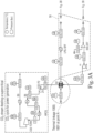
- Fig. 1 displays a diagram of an exemplary system for CO 2 and liquid hydrocarbon transport, which utilizes heat/cold integration of the CO 2 and liquid hydrocarbon facilities in accordance with one or more embodiments.
- the system comprises a first location, "Point A” (denoted by the dotted line), which includes a CO 2 loading facility and a hydrocarbon unloading facility, a second location, “Point B,” (denote by the dashed line) having a hydrocarbon loading facility and a CO 2 unloading facility, and a vessel 50 configured to alternatively transfer the liquid CO 2 and the liquid hydrocarbons between Points A and B.
- the hydrocarbon and CO 2 facilities at Points A and B comprise numerous containers, pipe, pipelines, connectors, gauges, and valves, for controlling the flow, temperature, and pressure of the CO 2 and hydrocarbon streams, for example, as would be understood by a person of ordinary skill in the art.
- the vessel 50 is represented in Fig. 1 as a marine vessel (e.g., ship or tanker), in other embodiments the vessel can be a land-based vehicle (e.g., tanker truck or tanker car for a train), or other type of carrier configured for transporting LPG and CO 2 .
- the liquid hydrocarbon represented in the figures and described in the following description is liquefied petroleum gas (LPG), in other embodiments other types of liquid hydrocarbons can be utilized such as liquefied natural gas (LNG).
- LPG liquefied petroleum gas
- LNG liquefied natural gas
- the vessel 50 can have one or more storage containers (storage tanks) 52 for storing the CO 2 and/or the liquid hydrocarbon (e.g., LPG).
- a typical LNG marine carrier has four to six storage tanks located along the center-line of the marine vessel. Surrounding these storage tanks is a combination of ballast tanks, cofferdams and voids so as to, in effect, provide the marine vessel a double-hull type design.
- each storage tank there are typically three submerged pumps.
- the spray pump is used for either pumping out liquid LNG to be used as fuel (via a vaporizer), or for cooling down cargo tanks. It can also be used for "stripping" out the last of the cargo in discharge operations. All of these pumps are contained within what is known as the pump tower which hangs from the top of the tank and runs the entire depth of the tank.
- the pump tower also contains the tank gauging system and the tank filling line, all of which are located near die bottom of the tank.
- All cargo pumps typically discharge into a common pipe which runs along the deck of the vessel; it branches off to either side of the vessel to the cargo manifolds, which are used for loading or discharging. All cargo tank vapor spaces are linked via a vapor header which runs parallel to the cargo header. This also has connections to the sides of the ship next to the loading and discharging manifolds.
- the fluid in this case either LPG or CO 2 or other suitable fluid (liquid or gas) passes through cargo manifolds for the loading and unloading of the respective cargo (e.g., in this case and according to one embodiment, LPG or CO 2 ).
- an LPG stream can be produced at an LPG production unit 10 via fractionation of and subsequent liquefaction of gas condensates and a petroleum stream. It will be appreciated that any number of conventional techniques can be used to produce the LPG stream.
- the produced LPG stream can then be transported via line 100 (e.g., conduit, piping) to an LPG storage facility 11 (such as a tank), where the LPG is stored at an appropriate temperature and pressure to maintain the LPG at liquid phase.
- lines refer to a conduit or piping configured to transfer fluids, including hydrocarbons and/or CO 2 , between the various production, processing, and storage units of the CO 2 and hydrocarbon facilities.
- LPG storage facility 11 is maintained at a temperature between approximately -50°C and ambient temperature and at a pressure between approximately 0.5 bar and 15 bar.
- these values are only exemplary and other storage conditions can be used depending upon the type of storage facility, etc.
- the LPG stream is withdrawn from the LPG storage facility 11 via line 101 and transferred to an LPG loading facility 12.
- the LPG stream is then transferred from the loading facility 12 via line 102 to the vessel 50.
- the system can further comprise a gaseous LPG line 120 that transfers back a portion of the LPG from the vessel to the LPG loading unit 12, the LPG storage facility 11, and/or the LPG production unit 10.
- Line 120 is used to control the pressure in the vessel because in instances in which the system cannot accommodate the overpressure, excess LPG could be flared.
- the vessel 50 transports the LPG from Point A (origin) to Point B (destination).
- the vessel 50 is selectively configured to maintain the LPG at a selected pressure and temperature for LPG transport, and is also configured to maintain a selected pressure and temperature for liquefied CO 2 transport, as discussed in further detail below.
- the LPG is unloaded from the vessel 50 through line 103 to LPG unloading unit 13.
- the LPG stream is then conveyed from unloading unit 13 to the LPG storage facility 14 via line 104.
- the LPG storage facility 14 can be, for example, a large volume facility to control in-country LPG distribution or could be of smaller capacity, built as a buffer for the LPG unloading before transfer to an industry or network.
- the LPG storage facility 14 (unloading LPG storage facility) at Point B includes a gaseous LPG return line 121 that connects back to the vessel 50 to control the pressure in the LPG storage facility 14 and to flare or expel any excess pressure buildup in the system.
- the LPG stream can be subsequently conveyed from the storage facility 14 to a nearby LPG pipeline 15 via line 105, or alternatively to another industrial facility.
- the LPG stream can be fed via line 106 to a nearby hydrogen production facility 20, where the hydrogen production facility uses the LPG stream as a feedstock to produce hydrogen.
- the hydrogen production unit 20 can be based on steam reforming, partial oxidation, auto-thermal reforming or any other technology known to those skilled in the art that can produce hydrogen from hydrocarbon feedstocks. In such units, the hydrogen is separated from the synthetic gas and fed to a hydrogen network or is consumed in a nearby industry (line 200).
- the hydrogen production unit 20 can also be operatively connected to a CO 2 capture unit 30.
- the CO 2 capture unit 30 is configured to capture the CO 2 from the synthetic gas of the hydrogen production unit 20 (via line 300) that is usually conveyed at high pressure.
- a second CO 2 capture unit can be present that captures CO 2 from a furnace flue gas (i.e., a low-pressure CO 2 stream) in an embodiment in which the hydrogen production unit 20 utilizes a steam LPG reforming process to make hydrogen.
- these two CO 2 capture units can be combined in one single unit treating the high-pressure and the low-pressure CO 2 streams.
- the CO 2 from the hydrogen production unit 20 can be captured from a high-pressure reformer and the CO 2 capture rate can be adapted to match the maximum CO 2 capacity that can be transported in the LPG/CO 2 vessel back to Point A.
- the CO 2 capture unit can be designed and operated to capture the CO 2 such that a portion is transported in the vessel, and another portion is saved for use in the nearby industry (line 400).
- the CO 2 capture unit 30 can be utilized to capture CO 2 produced from carbon containing source.
- the CO2 capture unit 30 can be utilized to capture CO2 produced from the hydrogen production unit 20 and/or a nearby pipeline (line 301).
- the CO2 captured by the capture unit 30 can be produced from the reforming of hydrocarbons such as LPG, or from the combustion of fossil fuels or biomass.
- the CO2 capture unit 30 can capture CO2 directly from the air.
- the CO2 is produced from the hydrogen production unit that is fed with hydrocarbons (LPG or natural gas), in addition to cases where the CO2 can be captured far from the port from various sources and then transferred to the port via pipeline.
- CO 2 captured by CO 2 capture unit 30 can then be transferred via line 302 to a CO 2 liquefaction unit 31 where the CO 2 is conditioned and liquefied to desired storage conditions and/or CO 2 transport conditions.
- the liquefied CO 2 is then fed to a CO 2 storage facility 32 via line 303 to gather the necessary volume for loading and transport in the vessel 50.
- the CO 2 capture unit 30 and the CO 2 liquefaction unit 31 can be a single unit, such as a CO 2 purification unit based on cold or cryogenic separation or distillation.
- a CO 2 purification unit based on cold or cryogenic separation or distillation.
- Many configurations for CO 2 capture and liquefaction are known in the art for capturing CO 2 by separation or liquefaction as exemplified in Fig. 5 and as shown and described in Gang Xu et al., Energys 2014, 7, 3484-3502 , doi:10.3390/en7053484, which is hereby incorporated by reference.
- the thermal linkage 1110 as shown in Fig. 1 can be operatively connected between the combined capture and liquefaction unit and the cold LPG stream at line 103A and/or the LPG storage unit 14.
- the thermal linkage 1100 and/or 1110 can be provided between the LPG and one or many of the internal heat exchangers or external heat exchangers H1, H2, H3, H4, H5 and H6, and/or the streams in-between them as shown in Fig. 5 .
- LPG coldness configuration can be thermally linked to any or multiple streams or heat exchangers in the CO 2 liquefaction unit that are at a temperature higher than the LPG stream temperature, which is generally between -50°C and ambient temperature.
- the thermal linkages 1100 and 1110 can be any mechanism known in the art for establishing thermal communication between the CO 2 liquefaction unit 31 and the LPG stream at line 103/103A and/or the LPG storage unit 14.
- the thermal linkages 1100 and/or 1110 can comprise a heat exchanger or a thermal transfer loop that transfers the coldness of the LPG stream to the CO 2 liquefaction unit 31 such that it can contribute to the reduction of the temperature of the CO 2 stream and its liquefaction energy and thus functioning as a cold sink. Due to the low temperature of LPG stream, line 103/103A and/or the LPG storage unit 14 can act as cold sink for the CO 2 liquefaction unit 31.
- the thermal transfer loop can contain transfer fluid having a low freezing point, for example, and the transfer fluid can be circulated within the thermal transfer loop using a pump or other practical means.
- Thermal transfer of the coldness from the LPG (line 103/103A and or the LPG storage unit 14) to the CO 2 liquefaction unit 31 via the thermal transfer loop (thermal linkages 1100 and 1110) can be accomplished in various ways known in the art, including via heat exchanger fins or coils, heat pipes, along with a suitable heat exchanger fluid for example high normal boiling point temperature hydrocarbons such as pentane, hexane, or water ethylene glycol mixtures.
- the CO 2 liquefaction unit 31 can be independent of the CO 2 capture unit 30, as shown in Fig. 1 .
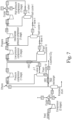
- the CO 2 liquefaction unit can be based on an external refrigeration system or a closed loop system such as the system presented in Fig. 7 and shown and described in Youngkyun Seo et al., Comparison of CO2 Liquefaction Pressures for Ship-Based Carbon Capture and Storage (CCS) Chain, International Journal of Greenhouse Gas Control, 52 (2016), 1-12 , which is hereby incorporated by reference.
- the CO 2 liquefaction unit can be based on an open loop system such as the Linde Hampson system (pictured in Fig.
- thermal linkage 1100 and/or 1110 can be provided between the LPG and one or many of heat exchangers HX1, HX2, Flash cooler I, Flash cooler II, and/or the streams in-between them, and or line 711 as shown in Fig. 7 .
- thermal linkage 1100 and/or 1110 can be provided between the LPG and one or many of heat exchangers: Heat exchanger I, Heat exchanger II, and/or the streams in-between them and/or line 813 as shown in Fig. 8 .
- CO 2 can be conveyed to the CO 2 loading facility 33 through a pipeline and can be pre-conditioned.
- a CO 2 liquefaction process at unit 31 is still needed, however its configuration could be different from the various liquefaction units presented above.
- Fig. 9 shows an optimized process configuration for pipeline CO 2 liquefaction as shown and described in Frithjof Engel, Improvements on the Liquefaction of a Pipeline CO2 Stream for Ship Transport, International Journal of Greenhouse Gas Control 72 (2016) 214-221 , which is hereby incorporated by reference.
- thermal linkage 1100 and/or 1110 of the present system as shown in Fig.
- the CO 2 loading facility 33 withdraws the CO 2 from the CO 2 storage facility 32 via line 304 and transfers it to the vessel 50 via line 305.
- a gaseous CO 2 return line to the CO 2 liquefaction unit 31 and/or CO 2 storage facility 32 can be utilized to control the pressure in the vessel 50 during loading of the CO 2 . If transported over long distances, the CO2 can be transported through pipelines in supercritical state. In such case, the supercritical CO2 would be liquefied before transferred to the vessel 50.
- the vessel 50 can be configured to allow for simultaneous loading of CO 2 and unloading of LPG, and conversely, simultaneous loading of LPG and unloading of CO 2 .
- the vessel 50 is configured to unload LPG through line 103 and simultaneously load the CO 2 through line 305.
- the LPG unloading line 103 and/or line 104 can be in thermal linkage 1100 with the CO 2 liquefaction unit 31 such that the coldness of the LPG stream can contribute to the reduction of the temperature of the CO 2 stream and its liquefaction.
- thermal linkage refers to one or more heat exchangers; heat transfer through a heat pipe or through an intermediate fluid loop; heat transfer through an intermediate solid material that is heated by the hotter stream and cooled by the colder stream; or other means known to a person skilled in the art that allow for the heat transfer (or cold transfer) between two streams.
- LPG unloading line 103 can be fed to an expansion device 16 before transfer to the LPG unloading unit 13 via line 103A.
- the feeding of at least a portion of the unloaded LPG to the expansion device 16 reduces the pressure of the LPG as well its temperature.
- line 103A is in thermal linkage (e.g., via thermal linkage 1110) with one or more of the following: the CO 2 liquefaction unit 31, the CO 2 loading stream 305, the CO 2 vapor stream connecting the vessel 50 to the CO 2 storage facility 32 or CO 2 liquefaction unit 31, and/or the LPG storage unit 14.
- the thermal linkage 1110 between line 103 and one or more of the above lines or units can allow the low temperature, low pressure LPG stream in line 103A to maintain its temperature.
- the higher temperature LPG stream (line 103) can be compressed and re-liquefied before it is fed to storage.
- the vessel 50 can transport the CO 2 from Point B to Point A.
- the vessel 50 can transport all or a portion of the CO 2 to another land-based, on-shore or off-shore unloading point.
- the CO 2 can be transported as a slurry which is a mix of solid CO 2 in suspension in liquid CO 2 to maximize the CO 2 intake and avail latent heat to curb the heat losses and boil-off of the CO 2 during transport.
- the vessel 50 can have a dedicated compression and liquefaction unit to condense the LPG boil-off during transport and another compression and liquefaction unit for the CO 2 boil-off liquefaction.
- the vessel 50 can use the same boil-off liquefaction unit for both CO 2 and LPG.
- Fig. 4 shows a typical LPG/CO 2 transport scheme having a vessel with a boil-off compression and liquefaction unit 69 in accordance with one or more embodiments.
- incondensable compounds can be separated from the CO 2 stream during transport on vessel 50.
- the system of the present application discloses a boil-off liquefaction unit comprising a nitrogen separation unit or non-condensable separation unit 61, which reduces the non-condensable gases content in the liquid CO 2 and reduce the energy spent for the boil-off re-liquefaction.
- the non-condensable separation unit 61 is shown as a nitrogen (N 2 ) separation unit.
- N 2 nitrogen
- non-condensable gases other than nitrogen can also be separated from the CO2 in separation unit 61, including but not limited O2, CO or methane.
- a boil-off stream 601 in the vessel is compressed in a boil-off compression unit 60 and fed through line 602 to a non-condensable separation unit 61 where nitrogen and other incondensable compounds are separated from the CO 2 stream.
- the separated nitrogen (N 2 ) and incondensable compounds are removed from the separation unit 61 via line 603.
- the separated CO 2 stream is then transferred to the boil-off liquefaction unit 62 where it is liquefied before being fed back to storage container 52 of the vessel 50 through line 605. Accordingly, using the boil-off liquefaction and compression units and the non-condensable separation unit, the present system can purify the CO 2 while it is being transported on the vessel 50.
- Separation unit 61 can be based on membrane technology, adsorption technology or any other technology known in the art that can separate nitrogen and incondensable compounds from the CO 2 stream.
- Preferred embodiments for separation unit 61 comprise membrane technology and/or cryogenic separation.
- unit 61 can be a cryogenic unit that simultaneously liquefies the CO 2 and reject the incondensable compounds, such as the separation unit (presented in Fig. 5 ) and shown and described in Gang Xu et al., Energys 2014, 7, 3484-3502, doi:10.3390/en7053484 , which is hereby incorporated by reference.
- the CO 2 is transported from Point B to Point A
- the CO 2 upon reaching Point A the CO 2 is transferred out of the vessel via line 306 to CO 2 unloading unit 34, which then conveys the CO 2 into an intermediate CO 2 storage facility 35 via line 307.
- the CO 2 can be conveyed through line 308 to a CO 2 compression station (unit) 36, where the CO 2 stream is compressed to a predetermined CO 2 utilization pressure or CO 2 pipeline pressure.
- at least a portion of the compressed CO 2 can then be transported out of station 36 through line 309 and into a CO 2 pipeline 38.
- point A can also comprises a supercritical CO 2 cycle 37 that is operatively connected to the CO 2 compression station 36 and/or the CO 2 pipeline 38. At least a portion of the compressed CO 2 from station 36 can be fed to the supercritical CO 2 cycle 37 via line 310.
- CO 2 withdrawn from the CO 2 storage facility 35 (generally operated between approximately -50°C and ambient temperature) is compressed in the CO 2 compression station 36 to a CO 2 pipeline pressure.
- the CO 2 pipeline pressure can be in the range of approximately 10 bar to approximately 200 bar, and in at least one embodiment, above 200 bar.
- at least a portion of the CO 2 can then be conveyed to utilization plants, sequestered underground in aquifers or geological formations, or used for enhanced oil recovery or reservoir pressurization.
- the CO 2 compression unit 36 compresses the CO 2 to a pressure above the CO 2 pipeline pressure (typically 200 to 500 bar) and provides at least a portion of the CO 2 to a supercritical CO 2 unit 37 via line 310 where the CO 2 is used as a motive fluid to produce power.
- a supercritical CO 2 unit e.g., supercritical CO 2 bottoming cycle
- Fig. 2 An exemplary a supercritical CO 2 unit (e.g., supercritical CO 2 bottoming cycle) in accordance with one or more embodiments is provided in Fig. 2 .
- a high pressure cold CO 2 stream is put in thermal linkage with LPG facilities (thermal linkages 1010 and 1011 as shown in Fig. 1 ) before being further heated in internal heat exchanger 2000.
- the CO 2 stream can then be transferred via line 320 to an external heat exchanger 2001 in heat linkage 1030 with a heat source 40.
- Heat source 40 can be waste heat available in adjacent plants or heat from the utility area of the LPG production facility or any heat available from a nearby industry, for example.
- This heat linkage 1030 can allow the temperature of the CO 2 stream exiting the external heat exchanger 2001 at line 321 to reach approximately 100°C to 800°C.
- This high-pressure, high-temperature CO 2 stream (in line 321) can then be conveyed to CO 2 turbine 2003 where it is expanded to generate mechanical work and eventually electricity.
- the CO 2 stream exiting the CO 2 turbine 2003 via line 322 has a pressure that is just above the CO 2 pipeline pressure and has a temperature between approximately 80°C and approximately 700°C.
- the CO 2 stream in line 322 can then be fed back to the internal heat exchanger 2000 where it is cooled, while heating the incoming high-pressure CO 2 stream from line 310, and then exits heat exchanger 2000 through line 311 to feed the CO 2 pipeline 38.
- the CO 2 compression station 36 can be a multistage compression system in which a portion of the CO 2 is compressed to the CO 2 pipeline pressure and conveyed to the CO 2 pipeline 38 through line 309 while a remaining portion of the CO 2 stream is compressed to a higher pressure and fed to the supercritical CO 2 cycle 37 through line 310.
- a thermal linkage 1000 can exist between the CO 2 unloading line 306 and the LPG loading line 102 or LPG line 101.
- the thermal linkage 1000 allows for heat transfer between the LPG stream (typically maintained at temperature between ambient and approximately -40°C) and the CO 2 stream (typically maintained between the CO 2 triple point temperature [approximately -56°C] and +10°C). This heat transfer allows the LPG stream to be further cooled and stored in the vessel 50 at lower temperature as compared with the LPG storage facility 11.
- the additional coldness of the LPG stream can be used for maintaining the temperature of the LPG stream at the LPG unloading location (Point B) and/or for additional energy transfer.
- CO 2 unloading line 306 can be in thermal linkage with gaseous LPG line 120 (thermal linkage 1001), which allows for the condensation of the gaseous LPG, reducing the load on the LPG production unit 10 and/or the LPG storage facility 11.
- the thermal linkages 1000 and 1001 can comprise one or more heat exchangers or thermal transfer loops that can contain transfer fluid having a low freezing point, for example.
- the transfer fluid can be circulated within the thermal transfer loop using a pump or other practical means.
- Thermal transfer between the LPG lines (lines 102 and 120) and the CO 2 line 306 via the thermal transfer loop(s) (thermal linkages 1000 and 1001) can be accomplished in various ways known in the art, including via heat exchanger fins or coils, heat pipes, along with a suitable heat exchanger fluid for example high normal boiling point temperature hydrocarbons such as pentane, hexane, or water ethylene glycol mixtures.
- two vessels 50 can be used for simultaneously loading/unloading of the liquid hydrocarbon (e.g., LPG) and the CO2, and the vessels can be linked together via one or more thermal linkages.
- a first vessel can arrive and start unloading the LPG at point B, and a second vessel can arrive few hours or a day later (depending on the amount of fluid to unload) to unload its LPG cargo as well.
- the storage tanks of the first vessel can undergo purging and conditioning for receiving CO2.
- the coldness of the LPG being offloaded from second vessel can be used to cool the CO2 stream being loaded on to the first vessel or to provide coldness to the CO2 liquefaction unit that is connected to first vessel.
- the coldness of the CO 2 stream can contribute to the liquefaction of the LPG at LPG production unit 10 via thermal linkage 1010 and/or maintain the temperature of the LPG at the LPG storage facility 11 through thermal linkage 1011.
- Thermal linkages 1010 and 1011 can connect the LPG production unit 10 and/or the LPG storage facility 11 with one or more of line 307, line 309, line 310 and/or CO 2 storage facility 35. While Fig. 1 shows thermal heat linkage 1011 as being operatively connected to LPG storage unit 11, in at least one embodiment, thermal linkage 1011 can be operatively connected to the LPG production unit 10 and/or LPG line 100.
- the thermal linkages 1010 and 1011 can comprise one or more heat exchangers or thermal transfer loops that can contain transfer fluid having a low freezing point, for example.
- the transfer fluid can be circulated within the thermal transfer loop using a pump or other practical means.
- Thermal transfer between the LPG facilities (LPG production unit 10, LPG production unit 11) and the CO 2 facilities (supercritical CO 2 cycle 37, CO 2 storage 35) liquefaction unit 31 via the thermal transfer loop can be accomplished in various ways known in the art, including via heat exchanger fins or coils along with a suitable heat exchanger fluid, for example high normal boiling point temperature hydrocarbons such as pentane, hexane, or water ethylene glycol mixtures. It should also be understood that other thermal linkages of the systems of the present application can be arranged in a similar fashion or by other practical means as would be understood by those skilled in the art.
- the vessel can transport it from Point A to Point B.
- the vessel can transport all or a portion of the LPG load to another land-based, on-shore, or off-shore unloading point.
- the vessel 50 is configured to meet and maintain the pressure and temperature requirements for LPG during transport as well as for liquefied CO 2 during transport.
- the vessel can be configured to transport CO 2 between its triple point temperature (approximately -56°C) and +10°C, and at pressures between approximately 5 bar and approximately 50 bar.
- the vessel is configured to transport the CO 2 close to its triple point conditions, somewhere between the triple point temperature and -40°C and at a pressure between 5 and 15 bar.
- the vessel can have a dedicated refrigeration and liquefaction unit to condense the LPG boil-off along the way or can use the same boil-off liquefaction unit for CO2 and LPG.
- the vessel 50 can have one or more storage containers (storage tanks) 52 for storing the CO2 and/or the liquid hydrocarbon (e.g., LPG).
- the vessel 50 can have at least one dedicated storage container for the LPG (or other liquefied hydrocarbon stream) and at least one dedicated storage container for CO 2 .
- the storage containers for LPG and CO 2 can be semi-pressurized and refrigerated.
- a common storage container can be used to transport the LPG (or other liquefied hydrocarbon stream) and the CO2 in the respective directions of the transport scheme.
- conditioning on the storage tank e.g., depressurization, purging of the previously fluid, CO2 or LPG
- conditioning on the storage tank e.g., depressurization, purging of the previously fluid, CO2 or LPG
- each connector 51 can comprise two parts. A first part of the connector 51 selectively attached to the pipe/tubing of the loading and unloading facilities. Likewise, a second part of the connector 51 can be selectively attached to the pipe/tubing of the storage tank of the vessel. The first part and the second part of the connector 51 can be mate together the form a sealed connection between the pipe/tubing of the storage tank of the vessel and the pipe/tubing of the loading or unloading facilities.
- the vessel 50 can transport the liquid hydrocarbon stream and/or the CO 2 to locations other than Point A and Point B, such as other land-based, on-shore, or off-shore locations. Transportation to the other locations can be in lieu of transportation to Point A and/or Point B or in addition to transportation to Point A and/or Point B.
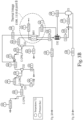
- Figs. 3A-3B provide a high-level diagram of an embodiment of the CO 2 and liquid hydrocarbon transport scheme, including exemplary thermal linkages (including heat exchangers B2 and CX2) in the transport scheme in accordance with one or more embodiments.
- Figs. 3A-3B displays a high-level scheme s featuring some of the integration options and levels of temperatures and pressures expected in the different flows.
- the same logic for co-transport of CO 2 with hydrocarbons as shown in Figs. 3A-3B can be followed and can include the heat integration at both ends of the transport scheme.
- the LPG as shown in Figs. 1 and 3A-3B can be replaced by liquefied natural gas (LNG).
- LNG liquefied natural gas
- CO 2 and LNG can be transported in the same vessel and can have heat integration at both terminals (i.e., Points A and B).
- a primary difference in such an embodiment is that LNG is transported at a temperature lower than CO 2 , so LNG coldness is used at the destination terminal (i.e., Point B) to liquefy the CO 2 and maintain the temperature of the CO 2 storage facility.
- Point A the CO 2 coldness is used to assist the liquefaction of the LNG.
- the CO 2 feeding the supercritical CO 2 cycle would remain the same in all cases.
- LPG can be replaced by other hydrocarbon-based substances (preferably between C1 to C7 hydrocarbons individually or as mixture) such as ethylene, dimethyl ether (DME), or any other hydrogen carrier with the optionality to transport back the CO 2 .
- LPG can be replaced by liquefied ammonia.
- the present systems and methods allow for heat transfer and energy recovery between the unloading and/or neighboring facility and the coldness of the transported goods (e.g., CO 2 and LPG).
- the present systems and methods allows for an effective re-liquefaction of the CO 2 boil-off and CO 2 purification while removing the non-condensable gases (e.g., nitrogen).
- the present systems and methods allow for the reduction of the CO 2 transport costs by allowing the usage of the same vessel that is carrying hydrocarbons such as LPG or ammonia to transport the CO 2 on its way back to load additional hydrocarbons instead of returning empty, which saves considerable CO 2 transport costs.
- the present systems and methods also teach coldness integration with the unloading terminal and/or nearby facilities which reduces the overall energy intensity at the unloading terminal.
- the present systems and methods also overcomes shortcomings in the field.
- liquid hydrogen i.e., liquid hydrocarbons
- other hydrogen carrier options such as ammonia or methylcyclohexane are expensive.
- current technologies do not link the energy recovery of the coldness of LPG and CO 2 at both terminal (e.g., in the present scheme, Point A and Point B).
- the present systems and methods allows for heat/cold integration in different parts of the transport chain and purifies the CO 2 feed while it is being transported in the vessel, thereby saving overall energy consumption and reducing the CO2 transport costs.
- the present systems can be a significant part of the overall Carbon Capture and Sequestration (CCS) chain.
- CCS Carbon Capture and Sequestration
Landscapes
- Engineering & Computer Science (AREA)
- Chemical & Material Sciences (AREA)
- Mechanical Engineering (AREA)
- General Engineering & Computer Science (AREA)
- Chemical Kinetics & Catalysis (AREA)
- Organic Chemistry (AREA)
- Physics & Mathematics (AREA)
- Thermal Sciences (AREA)
- General Health & Medical Sciences (AREA)
- Combustion & Propulsion (AREA)
- Inorganic Chemistry (AREA)
- Health & Medical Sciences (AREA)
- Filling Or Discharging Of Gas Storage Vessels (AREA)
Claims (10)
- Station de chargement et de déchargement pour le déchargement séquentiel du CO2 depuis au moins un réservoir de stockage dans une cuve et pour le chargement du GPL dans un réservoir de stockage de la même cuve, comprenant :une unité de production de GPL (10) ;une unité de stockage de GPL (11), l'unité de stockage (11) étant en communication fluidique avec l'unité de production de GPL (10) ;un premier raccord (51) pour la liaison fluidique à l'unité de stockage de GPL (11) afin de charger le GPL dans le réservoir de stockage de la cuve ;un deuxième raccord (51) pour le déchargement du CO2 dans une unité de stockage de CO2 (35) ;une unité de compression de CO2 (36) qui comprime le CO2 au-dessus d'une pression prédéterminée ;une unité de CO2 supercritique (37) qui reçoit du CO2 depuis l'unité de compression (36), où l'unité de CO2 supercritique (37) est caractérisée par :un échangeur de chaleur interne (2000), un échangeur de chaleur externe (2001), et une turbine à CO2 (2003), où les échangeurs de chaleur interne et externe (2000, 2001) sont destinés à chauffer un flux de CO2 froid à haute pression afin de former un flux de CO2 à haute température et à haute pression et où la turbine à CO2 (2003) est destinée à dilater le flux de CO2 à haute température et à haute pression afin de générer de l'énergie ; etdes liaisons thermiques (1010, 1011) qui mettent en contact le flux de CO2 froid à haute pression provenant de l'unité de CO2 supercritique (37) et de l'unité de compression de CO2 (26) avec l'unité de production de GPL (10) et l'unité de stockage de GPL (11), comprenant :
(A) une première liaison thermique (1010) qui est destinée à transférer le froid provenant du flux de CO2 froid afin de faciliter la liquéfaction du GPL dans l'unité de production de GPL (10) et (B) une deuxième liaison thermique (1011) qui est destinée à maintenir la température de l'unité de stockage de GPL (11). - Station de chargement et de déchargement selon la revendication 1,dans laquelle l'échangeur de chaleur interne (2000) est destiné à chauffer le flux de CO2 froid à haute pression et transférer le flux de CO2 froid à haute pression à l'échangeur de chaleur externe (2001),dans laquelle l'échangeur de chaleur externe (2001) est destiné à continuer à chauffer le flux de CO2 froid à haute pression afin de créer le flux de CO2 à haute température et à haute pression, et destiné à transférer le flux de CO2 à haute température et à haute pression à la turbine à CO2 (2003).
- Station de chargement et de déchargement selon la revendication 2, comprenant en outre :
une source de chaleur (40) reliée de manière fonctionnelle à l'échangeur de chaleur externe (2001) par le biais d'une liaison thermique (1030), où la source de chaleur (40) fournit de l'énergie pour chauffer le flux de CO2 froid à haute pression dans l'échangeur de chaleur externe (2001). - Station de chargement et de déchargement selon la revendication 3, dans laquelle le flux de CO2 à haute température et à haute pression sortant de l'échangeur de chaleur externe (2001) a une température dans une plage allant de 100°C à 800°C.
- Station de chargement et de déchargement selon la revendication 1, dans laquelle l'unité de compression de CO2 (36) comprime le CO2 à une pression dans la plage de 200 à 500 bar.
- Station de chargement et de déchargement selon la revendication 1, comprenant en outre :
une unité de chargement de GPL (12) destinée à transférer le GPL depuis l'unité de stockage de GPL (11) au ou aux réservoirs de stockage dans la cuve par le biais du premier raccord (51). - Station de chargement et de déchargement selon la revendication 6, comprenant en outre :
une unité de déchargement de CO2 (34) destinée à transférer du CO2 depuis le ou les réservoirs de stockage dans la cuve à l'unité de stockage de CO2 (35). - Station de chargement et de déchargement selon la revendication 7, comprenant en outre :
une troisième liaison thermique (1000), où la troisième liaison thermique (1000) est destinée à transférer de la chaleur entre le GPL en cours de transfert depuis l'unité de chargement de GPL (12) et le CO2 en cours de transfert à l'unité de déchargement de CO2 (34). - Station de chargement et de déchargement selon la revendication 3, dans laquelle la source de chaleur est de la chaleur résiduaire provenant d'une installation utilitaire adjacente.
- Station de chargement et de déchargement selon la revendication 1, comprenant en outre :
un pipeline de CO2 (38) en communication fluidique avec l'unité de compression de CO2 (36) et l'unité de CO2 supercritique (37), où la conduite de CO2 est destinée à recevoir au moins une partie du CO2 comprimé provenant de l'unité de compression de CO2 (36).
Applications Claiming Priority (2)
| Application Number | Priority Date | Filing Date | Title |
|---|---|---|---|
| US201962797031P | 2019-01-25 | 2019-01-25 | |
| PCT/US2020/014992 WO2020154621A1 (fr) | 2019-01-25 | 2020-01-24 | Processus et procédé de transport d'hydrocarbure liquide et de co2 pour la production d'hydrogène avec capture de co2 |
Publications (2)
| Publication Number | Publication Date |
|---|---|
| EP3914848A1 EP3914848A1 (fr) | 2021-12-01 |
| EP3914848B1 true EP3914848B1 (fr) | 2024-10-23 |
Family
ID=70009358
Family Applications (1)
| Application Number | Title | Priority Date | Filing Date |
|---|---|---|---|
| EP20714724.0A Active EP3914848B1 (fr) | 2019-01-25 | 2020-01-24 | Processus et procédé de transport d'hydrocarbure liquide et de co2 pour la production d'hydrogène avec capture de co2 |
Country Status (7)
| Country | Link |
|---|---|
| US (1) | US11125391B2 (fr) |
| EP (1) | EP3914848B1 (fr) |
| JP (1) | JP7434334B2 (fr) |
| KR (1) | KR102806470B1 (fr) |
| CN (1) | CN113195961B (fr) |
| SG (1) | SG11202105693VA (fr) |
| WO (1) | WO2020154621A1 (fr) |
Families Citing this family (25)
| Publication number | Priority date | Publication date | Assignee | Title |
|---|---|---|---|---|
| CA3104319C (fr) | 2019-12-30 | 2023-01-24 | Marathon Petroleum Company Lp | Procedes et systemes de gestion du refoulement dans le melange en conduite de liquides d'hydrocarbures |
| US11607654B2 (en) | 2019-12-30 | 2023-03-21 | Marathon Petroleum Company Lp | Methods and systems for in-line mixing of hydrocarbon liquids |
| US11559774B2 (en) | 2019-12-30 | 2023-01-24 | Marathon Petroleum Company Lp | Methods and systems for operating a pump at an efficiency point |
| US10990114B1 (en) | 2019-12-30 | 2021-04-27 | Marathon Petroleum Company Lp | Methods and systems for inline mixing of hydrocarbon liquids |
| US12012883B2 (en) | 2021-03-16 | 2024-06-18 | Marathon Petroleum Company Lp | Systems and methods for backhaul transportation of liquefied gas and CO2 using liquefied gas carriers |
| US11578638B2 (en) | 2021-03-16 | 2023-02-14 | Marathon Petroleum Company Lp | Scalable greenhouse gas capture systems and methods |
| US11655940B2 (en) | 2021-03-16 | 2023-05-23 | Marathon Petroleum Company Lp | Systems and methods for transporting fuel and carbon dioxide in a dual fluid vessel |
| US11578836B2 (en) | 2021-03-16 | 2023-02-14 | Marathon Petroleum Company Lp | Scalable greenhouse gas capture systems and methods |
| US12180597B2 (en) | 2021-08-26 | 2024-12-31 | Marathon Petroleum Company Lp | Test station assemblies for monitoring cathodic protection of structures and related methods |
| US12129559B2 (en) | 2021-08-26 | 2024-10-29 | Marathon Petroleum Company Lp | Test station assemblies for monitoring cathodic protection of structures and related methods |
| US12043905B2 (en) | 2021-08-26 | 2024-07-23 | Marathon Petroleum Company Lp | Electrode watering assemblies and methods for maintaining cathodic monitoring of structures |
| US11447877B1 (en) | 2021-08-26 | 2022-09-20 | Marathon Petroleum Company Lp | Assemblies and methods for monitoring cathodic protection of structures |
| EP4191177A1 (fr) * | 2021-12-01 | 2023-06-07 | Nederlandse Organisatie Voor Toegepast- Natuurwetenschappelijk Onderzoek Tno | Optimisation énergétique du lng pour sbcc |
| US11686070B1 (en) | 2022-05-04 | 2023-06-27 | Marathon Petroleum Company Lp | Systems, methods, and controllers to enhance heavy equipment warning |
| FR3140343B1 (fr) * | 2022-10-03 | 2024-08-30 | Gaztransport Et Technigaz | Dispositif de support d’au moins un instrument sur une tour de chargement et/ou de déchargement d’une cuve d’un navire destinée à contenir un gaz liquéfié |
| US12012082B1 (en) | 2022-12-30 | 2024-06-18 | Marathon Petroleum Company Lp | Systems and methods for a hydraulic vent interlock |
| WO2024163698A1 (fr) * | 2023-02-01 | 2024-08-08 | Kraken Technology Holdings, LLC | Procédé d'utilisation d'énergie froide à partir d'une installation de réception de dioxyde de carbone liquide |
| US12331888B2 (en) * | 2023-02-01 | 2025-06-17 | Kraken Technology Holdings, LLC | Process for cold energy utilization from a liquid carbon dioxide receiving facility |
| US12006014B1 (en) | 2023-02-18 | 2024-06-11 | Marathon Petroleum Company Lp | Exhaust vent hoods for marine vessels and related methods |
| US12043361B1 (en) | 2023-02-18 | 2024-07-23 | Marathon Petroleum Company Lp | Exhaust handling systems for marine vessels and related methods |
| KR20240155659A (ko) * | 2023-04-20 | 2024-10-29 | 주식회사 패리티 | 암모니아 예냉 방식을 이용한 수소 액화 시스템 |
| US12297965B2 (en) | 2023-08-09 | 2025-05-13 | Marathon Petroleum Company Lp | Systems and methods for mixing hydrogen with natural gas |
| US12597151B2 (en) | 2023-09-18 | 2026-04-07 | Marathon Petroleum Company Lp | Systems and methods to determine vegetation encroachment along a right-of-way |
| KR102862979B1 (ko) * | 2023-11-29 | 2025-09-22 | 한화오션 주식회사 | 이종 화물 운반선 및 이종 화물 운반선의 화물 치환방법 |
| EP4678967A1 (fr) * | 2024-07-09 | 2026-01-14 | Tree Energy Solutions B.V. | Dechargement et chargement de liquides cryogeniques |
Family Cites Families (20)
| Publication number | Priority date | Publication date | Assignee | Title |
|---|---|---|---|---|
| NO324883B1 (no) | 2001-12-03 | 2007-12-27 | Statoil Asa | Fartoy |
| JP2004125039A (ja) | 2002-10-01 | 2004-04-22 | Mitsubishi Heavy Ind Ltd | Co2運搬方法、流体貯蔵装置、プラグ発射装置、プラグ回収装置及び流体貯蔵方法 |
| NO330732B1 (no) | 2003-12-16 | 2011-06-27 | Sargas As | Kombinert lager for naturgass og CO2 |
| US7069742B2 (en) * | 2004-01-19 | 2006-07-04 | Air Products And Chemicals, Inc. | High-pressure delivery system for ultra high purity liquid carbon dioxide |
| GB2416390B (en) * | 2004-07-16 | 2006-07-26 | Statoil Asa | LCD Offshore Transport System |
| JP4105758B2 (ja) * | 2006-02-08 | 2008-06-25 | 松下電器産業株式会社 | 燃料電池システム |
| CN100470114C (zh) * | 2006-07-05 | 2009-03-18 | 中国科学院工程热物理研究所 | 利用液化天然气冷的二氧化碳零排放热力循环及流程 |
| GB0614250D0 (en) * | 2006-07-18 | 2006-08-30 | Ntnu Technology Transfer As | Apparatus and Methods for Natural Gas Transportation and Processing |
| BRPI0921922B1 (pt) | 2008-11-20 | 2021-02-23 | Single Buoy Moorings Inc | unidade multifuncional flutuante |
| FR2940413B1 (fr) * | 2008-12-19 | 2013-01-11 | Air Liquide | Procede de capture du co2 par cryo-condensation |
| KR101319364B1 (ko) * | 2011-05-31 | 2013-10-16 | 대우조선해양 주식회사 | 연료용 lng를 이용한 액화가스탱크 압력 조절장치 및 이를 가지는 액화가스운반선 |
| CN103619705A (zh) * | 2011-05-31 | 2014-03-05 | 大宇造船海洋株式会社 | 使用lng燃料的寒热回收设备及包含此设备的液化气运输船 |
| WO2013025108A1 (fr) * | 2011-08-18 | 2013-02-21 | Stamicarbon B.V. | Procédé de transport maritime pour le stockage du co2 et l'importation de cng |
| ITCO20110063A1 (it) * | 2011-12-14 | 2013-06-15 | Nuovo Pignone Spa | Sistema a ciclo chiuso per recuperare calore disperso |
| US9593883B2 (en) * | 2011-12-27 | 2017-03-14 | Daewoo Shipbuilding & Marine Engineering Co., Ltd. | Module for treatment of carbon dioxide and treatment method thereof |
| US10106430B2 (en) | 2013-12-30 | 2018-10-23 | Saudi Arabian Oil Company | Oxycombustion systems and methods with thermally integrated ammonia synthesis |
| AU2014224153B8 (en) | 2014-07-09 | 2015-07-02 | Woodside Energy Technologies Pty Ltd | System and method for heading control of a floating lng vessel using a set of real-time monitored hull integrity data |
| WO2017083778A1 (fr) * | 2015-11-14 | 2017-05-18 | New Fg Co, Llc | Procédé de transport de gaz naturel liquéfié et de dioxyde de carbone liquéfié |
| US10150535B2 (en) | 2016-03-02 | 2018-12-11 | 7 Seas Technology AS | Systems, methods and units for offloading or loading cargo at sea |
| GB2559149B (en) | 2017-01-26 | 2022-04-20 | Equinor Energy As | Offshore CO2 transport system |
-
2020
- 2020-01-24 EP EP20714724.0A patent/EP3914848B1/fr active Active
- 2020-01-24 CN CN202080006409.8A patent/CN113195961B/zh active Active
- 2020-01-24 KR KR1020217014435A patent/KR102806470B1/ko active Active
- 2020-01-24 WO PCT/US2020/014992 patent/WO2020154621A1/fr not_active Ceased
- 2020-01-24 US US16/751,905 patent/US11125391B2/en active Active
- 2020-01-24 SG SG11202105693VA patent/SG11202105693VA/en unknown
- 2020-01-24 JP JP2021540199A patent/JP7434334B2/ja active Active
Also Published As
| Publication number | Publication date |
|---|---|
| US20200240588A1 (en) | 2020-07-30 |
| CN113195961B (zh) | 2023-05-23 |
| JP2022518183A (ja) | 2022-03-14 |
| KR102806470B1 (ko) | 2025-05-12 |
| CN113195961A (zh) | 2021-07-30 |
| EP3914848A1 (fr) | 2021-12-01 |
| KR20210118058A (ko) | 2021-09-29 |
| JP7434334B2 (ja) | 2024-02-20 |
| US11125391B2 (en) | 2021-09-21 |
| WO2020154621A1 (fr) | 2020-07-30 |
| SG11202105693VA (en) | 2021-06-29 |
Similar Documents
| Publication | Publication Date | Title |
|---|---|---|
| EP3914848B1 (fr) | Processus et procédé de transport d'hydrocarbure liquide et de co2 pour la production d'hydrogène avec capture de co2 | |
| KR102116718B1 (ko) | 액체 질소를 저장하는 lng 운반선에서의 천연 가스 액화 방법 | |
| US7478975B2 (en) | Apparatus for cryogenic fluids having floating liquefaction unit and floating regasification unit connected by shuttle vessel, and cryogenic fluid methods | |
| KR101617021B1 (ko) | 연료가스 공급시스템 | |
| US20110297346A1 (en) | Methods and Systems of Regenerative Heat Exchange | |
| US20130192297A1 (en) | Configurations and methods for small scale lng production | |
| CN109661535B (zh) | 用于小型lng生产的构造和方法 | |
| EP3374257A1 (fr) | Navire de liquéfaction de gaz naturel | |
| KR20100124537A (ko) | 이산화탄소 하역과 화물 하역이 가능한 항구 | |
| US20200386473A1 (en) | Apparatus, system and method for reliquefaction of previously regasified lng | |
| KR101637450B1 (ko) | 선박의 증발가스 처리 시스템 및 방법 | |
| EP3589881B1 (fr) | Systèmes et procédés de transport de gaz naturel liquéfié | |
| KR101686510B1 (ko) | 선박의 증발가스 처리 시스템 및 방법 | |
| WO2014086413A1 (fr) | Système intégré et amélioré pour le transport maritime de gaz naturel comprimé dans des cuves, comprenant de multiples étapes de traitement pour abaisser la température combinant le refroidissement et la réfrigération | |
| CN115289394A (zh) | 浮体设备 | |
| KR20250064018A (ko) | 부유식 청정 암모니아 저장 플랜트 |
Legal Events
| Date | Code | Title | Description |
|---|---|---|---|
| STAA | Information on the status of an ep patent application or granted ep patent |
Free format text: STATUS: UNKNOWN |
|
| STAA | Information on the status of an ep patent application or granted ep patent |
Free format text: STATUS: THE INTERNATIONAL PUBLICATION HAS BEEN MADE |
|
| PUAI | Public reference made under article 153(3) epc to a published international application that has entered the european phase |
Free format text: ORIGINAL CODE: 0009012 |
|
| STAA | Information on the status of an ep patent application or granted ep patent |
Free format text: STATUS: REQUEST FOR EXAMINATION WAS MADE |
|
| 17P | Request for examination filed |
Effective date: 20210608 |
|
| AK | Designated contracting states |
Kind code of ref document: A1 Designated state(s): AL AT BE BG CH CY CZ DE DK EE ES FI FR GB GR HR HU IE IS IT LI LT LU LV MC MK MT NL NO PL PT RO RS SE SI SK SM TR |
|
| DAV | Request for validation of the european patent (deleted) | ||
| DAX | Request for extension of the european patent (deleted) | ||
| STAA | Information on the status of an ep patent application or granted ep patent |
Free format text: STATUS: EXAMINATION IS IN PROGRESS |
|
| 17Q | First examination report despatched |
Effective date: 20230503 |
|
| P01 | Opt-out of the competence of the unified patent court (upc) registered |
Effective date: 20230524 |
|
| GRAP | Despatch of communication of intention to grant a patent |
Free format text: ORIGINAL CODE: EPIDOSNIGR1 |
|
| STAA | Information on the status of an ep patent application or granted ep patent |
Free format text: STATUS: GRANT OF PATENT IS INTENDED |
|
| INTG | Intention to grant announced |
Effective date: 20240513 |
|
| GRAS | Grant fee paid |
Free format text: ORIGINAL CODE: EPIDOSNIGR3 |
|
| GRAA | (expected) grant |
Free format text: ORIGINAL CODE: 0009210 |
|
| STAA | Information on the status of an ep patent application or granted ep patent |
Free format text: STATUS: THE PATENT HAS BEEN GRANTED |
|
| AK | Designated contracting states |
Kind code of ref document: B1 Designated state(s): AL AT BE BG CH CY CZ DE DK EE ES FI FR GB GR HR HU IE IS IT LI LT LU LV MC MK MT NL NO PL PT RO RS SE SI SK SM TR |
|
| REG | Reference to a national code |
Ref country code: GB Ref legal event code: FG4D |
|
| REG | Reference to a national code |
Ref country code: CH Ref legal event code: EP |
|
| REG | Reference to a national code |
Ref country code: DE Ref legal event code: R096 Ref document number: 602020039854 Country of ref document: DE |
|
| REG | Reference to a national code |
Ref country code: NL Ref legal event code: FP Ref country code: IE Ref legal event code: FG4D |
|
| PGFP | Annual fee paid to national office [announced via postgrant information from national office to epo] |
Ref country code: NL Payment date: 20250121 Year of fee payment: 6 |
|
| REG | Reference to a national code |
Ref country code: LT Ref legal event code: MG9D |
|
| REG | Reference to a national code |
Ref country code: AT Ref legal event code: MK05 Ref document number: 1735100 Country of ref document: AT Kind code of ref document: T Effective date: 20241023 |
|
| PG25 | Lapsed in a contracting state [announced via postgrant information from national office to epo] |
Ref country code: HR Free format text: LAPSE BECAUSE OF FAILURE TO SUBMIT A TRANSLATION OF THE DESCRIPTION OR TO PAY THE FEE WITHIN THE PRESCRIBED TIME-LIMIT Effective date: 20241023 Ref country code: IS Free format text: LAPSE BECAUSE OF FAILURE TO SUBMIT A TRANSLATION OF THE DESCRIPTION OR TO PAY THE FEE WITHIN THE PRESCRIBED TIME-LIMIT Effective date: 20250223 Ref country code: PT Free format text: LAPSE BECAUSE OF FAILURE TO SUBMIT A TRANSLATION OF THE DESCRIPTION OR TO PAY THE FEE WITHIN THE PRESCRIBED TIME-LIMIT Effective date: 20250224 |
|
| PGFP | Annual fee paid to national office [announced via postgrant information from national office to epo] |
Ref country code: DE Payment date: 20250122 Year of fee payment: 6 |
|
| PG25 | Lapsed in a contracting state [announced via postgrant information from national office to epo] |
Ref country code: FI Free format text: LAPSE BECAUSE OF FAILURE TO SUBMIT A TRANSLATION OF THE DESCRIPTION OR TO PAY THE FEE WITHIN THE PRESCRIBED TIME-LIMIT Effective date: 20241023 |
|
| PG25 | Lapsed in a contracting state [announced via postgrant information from national office to epo] |
Ref country code: BG Free format text: LAPSE BECAUSE OF FAILURE TO SUBMIT A TRANSLATION OF THE DESCRIPTION OR TO PAY THE FEE WITHIN THE PRESCRIBED TIME-LIMIT Effective date: 20241023 |
|
| PG25 | Lapsed in a contracting state [announced via postgrant information from national office to epo] |
Ref country code: ES Free format text: LAPSE BECAUSE OF FAILURE TO SUBMIT A TRANSLATION OF THE DESCRIPTION OR TO PAY THE FEE WITHIN THE PRESCRIBED TIME-LIMIT Effective date: 20241023 |
|
| PG25 | Lapsed in a contracting state [announced via postgrant information from national office to epo] |
Ref country code: NO Free format text: LAPSE BECAUSE OF FAILURE TO SUBMIT A TRANSLATION OF THE DESCRIPTION OR TO PAY THE FEE WITHIN THE PRESCRIBED TIME-LIMIT Effective date: 20250123 |
|
| PG25 | Lapsed in a contracting state [announced via postgrant information from national office to epo] |
Ref country code: AT Free format text: LAPSE BECAUSE OF FAILURE TO SUBMIT A TRANSLATION OF THE DESCRIPTION OR TO PAY THE FEE WITHIN THE PRESCRIBED TIME-LIMIT Effective date: 20241023 Ref country code: LV Free format text: LAPSE BECAUSE OF FAILURE TO SUBMIT A TRANSLATION OF THE DESCRIPTION OR TO PAY THE FEE WITHIN THE PRESCRIBED TIME-LIMIT Effective date: 20241023 Ref country code: GR Free format text: LAPSE BECAUSE OF FAILURE TO SUBMIT A TRANSLATION OF THE DESCRIPTION OR TO PAY THE FEE WITHIN THE PRESCRIBED TIME-LIMIT Effective date: 20250124 |
|
| PG25 | Lapsed in a contracting state [announced via postgrant information from national office to epo] |
Ref country code: PL Free format text: LAPSE BECAUSE OF FAILURE TO SUBMIT A TRANSLATION OF THE DESCRIPTION OR TO PAY THE FEE WITHIN THE PRESCRIBED TIME-LIMIT Effective date: 20241023 |
|
| PGFP | Annual fee paid to national office [announced via postgrant information from national office to epo] |
Ref country code: FR Payment date: 20250121 Year of fee payment: 6 |
|
| PG25 | Lapsed in a contracting state [announced via postgrant information from national office to epo] |
Ref country code: RS Free format text: LAPSE BECAUSE OF FAILURE TO SUBMIT A TRANSLATION OF THE DESCRIPTION OR TO PAY THE FEE WITHIN THE PRESCRIBED TIME-LIMIT Effective date: 20250123 |
|
| PG25 | Lapsed in a contracting state [announced via postgrant information from national office to epo] |
Ref country code: SM Free format text: LAPSE BECAUSE OF FAILURE TO SUBMIT A TRANSLATION OF THE DESCRIPTION OR TO PAY THE FEE WITHIN THE PRESCRIBED TIME-LIMIT Effective date: 20241023 |
|
| PG25 | Lapsed in a contracting state [announced via postgrant information from national office to epo] |
Ref country code: DK Free format text: LAPSE BECAUSE OF FAILURE TO SUBMIT A TRANSLATION OF THE DESCRIPTION OR TO PAY THE FEE WITHIN THE PRESCRIBED TIME-LIMIT Effective date: 20241023 |
|
| PG25 | Lapsed in a contracting state [announced via postgrant information from national office to epo] |
Ref country code: EE Free format text: LAPSE BECAUSE OF FAILURE TO SUBMIT A TRANSLATION OF THE DESCRIPTION OR TO PAY THE FEE WITHIN THE PRESCRIBED TIME-LIMIT Effective date: 20241023 |
|
| PG25 | Lapsed in a contracting state [announced via postgrant information from national office to epo] |
Ref country code: RO Free format text: LAPSE BECAUSE OF FAILURE TO SUBMIT A TRANSLATION OF THE DESCRIPTION OR TO PAY THE FEE WITHIN THE PRESCRIBED TIME-LIMIT Effective date: 20241023 |
|
| REG | Reference to a national code |
Ref country code: DE Ref legal event code: R097 Ref document number: 602020039854 Country of ref document: DE |
|
| PG25 | Lapsed in a contracting state [announced via postgrant information from national office to epo] |
Ref country code: SK Free format text: LAPSE BECAUSE OF FAILURE TO SUBMIT A TRANSLATION OF THE DESCRIPTION OR TO PAY THE FEE WITHIN THE PRESCRIBED TIME-LIMIT Effective date: 20241023 |
|
| PG25 | Lapsed in a contracting state [announced via postgrant information from national office to epo] |
Ref country code: CZ Free format text: LAPSE BECAUSE OF FAILURE TO SUBMIT A TRANSLATION OF THE DESCRIPTION OR TO PAY THE FEE WITHIN THE PRESCRIBED TIME-LIMIT Effective date: 20241023 |
|
| PG25 | Lapsed in a contracting state [announced via postgrant information from national office to epo] |
Ref country code: IT Free format text: LAPSE BECAUSE OF FAILURE TO SUBMIT A TRANSLATION OF THE DESCRIPTION OR TO PAY THE FEE WITHIN THE PRESCRIBED TIME-LIMIT Effective date: 20241023 |
|
| PLBE | No opposition filed within time limit |
Free format text: ORIGINAL CODE: 0009261 |
|
| REG | Reference to a national code |
Ref country code: CH Ref legal event code: PL |
|
| STAA | Information on the status of an ep patent application or granted ep patent |
Free format text: STATUS: NO OPPOSITION FILED WITHIN TIME LIMIT |
|
| PG25 | Lapsed in a contracting state [announced via postgrant information from national office to epo] |
Ref country code: SE Free format text: LAPSE BECAUSE OF FAILURE TO SUBMIT A TRANSLATION OF THE DESCRIPTION OR TO PAY THE FEE WITHIN THE PRESCRIBED TIME-LIMIT Effective date: 20241023 |
|
| PG25 | Lapsed in a contracting state [announced via postgrant information from national office to epo] |
Ref country code: MC Free format text: LAPSE BECAUSE OF FAILURE TO SUBMIT A TRANSLATION OF THE DESCRIPTION OR TO PAY THE FEE WITHIN THE PRESCRIBED TIME-LIMIT Effective date: 20241023 Ref country code: LU Free format text: LAPSE BECAUSE OF NON-PAYMENT OF DUE FEES Effective date: 20250124 |
|
| GBPC | Gb: european patent ceased through non-payment of renewal fee |
Effective date: 20250124 |
|
| 26N | No opposition filed |
Effective date: 20250724 |
|
| PG25 | Lapsed in a contracting state [announced via postgrant information from national office to epo] |
Ref country code: BE Free format text: LAPSE BECAUSE OF NON-PAYMENT OF DUE FEES Effective date: 20250131 Ref country code: GB Free format text: LAPSE BECAUSE OF NON-PAYMENT OF DUE FEES Effective date: 20250124 |
|
| PG25 | Lapsed in a contracting state [announced via postgrant information from national office to epo] |
Ref country code: CH Free format text: LAPSE BECAUSE OF NON-PAYMENT OF DUE FEES Effective date: 20250131 |
|
| REG | Reference to a national code |
Ref country code: BE Ref legal event code: MM Effective date: 20250131 |
|
| PG25 | Lapsed in a contracting state [announced via postgrant information from national office to epo] |
Ref country code: IE Free format text: LAPSE BECAUSE OF NON-PAYMENT OF DUE FEES Effective date: 20250124 |