EP3914976B1 - Affectation d'outils à des emplacements dans un magasin d'outils - Google Patents
Affectation d'outils à des emplacements dans un magasin d'outils Download PDFInfo
- Publication number
- EP3914976B1 EP3914976B1 EP19710332.8A EP19710332A EP3914976B1 EP 3914976 B1 EP3914976 B1 EP 3914976B1 EP 19710332 A EP19710332 A EP 19710332A EP 3914976 B1 EP3914976 B1 EP 3914976B1
- Authority
- EP
- European Patent Office
- Prior art keywords
- tool
- tools
- assigned
- space
- transfer point
- Prior art date
- Legal status (The legal status is an assumption and is not a legal conclusion. Google has not performed a legal analysis and makes no representation as to the accuracy of the status listed.)
- Active
Links
Images





Classifications
-
- G—PHYSICS
- G05—CONTROLLING; REGULATING
- G05B—CONTROL OR REGULATING SYSTEMS IN GENERAL; FUNCTIONAL ELEMENTS OF SUCH SYSTEMS; MONITORING OR TESTING ARRANGEMENTS FOR SUCH SYSTEMS OR ELEMENTS
- G05B19/00—Program-control systems
- G05B19/02—Program-control systems electric
- G05B19/18—Numerical control [NC], i.e. automatically operating machines, in particular machine tools, e.g. in a manufacturing environment, so as to execute positioning, movement or co-ordinated operations by means of program data in numerical form
- G05B19/4093—Numerical control [NC], i.e. automatically operating machines, in particular machine tools, e.g. in a manufacturing environment, so as to execute positioning, movement or co-ordinated operations by means of program data in numerical form characterised by part programming, e.g. entry of geometrical information as taken from a technical drawing, combining this with machining and material information to obtain control information, named part program, for the NC machine
- G05B19/40937—Numerical control [NC], i.e. automatically operating machines, in particular machine tools, e.g. in a manufacturing environment, so as to execute positioning, movement or co-ordinated operations by means of program data in numerical form characterised by part programming, e.g. entry of geometrical information as taken from a technical drawing, combining this with machining and material information to obtain control information, named part program, for the NC machine concerning programming of machining or material parameters, pocket machining
- G05B19/40938—Tool management
-
- B—PERFORMING OPERATIONS; TRANSPORTING
- B23—MACHINE TOOLS; METAL-WORKING NOT OTHERWISE PROVIDED FOR
- B23Q—DETAILS, COMPONENTS, OR ACCESSORIES FOR MACHINE TOOLS, e.g. ARRANGEMENTS FOR COPYING OR CONTROLLING; MACHINE TOOLS IN GENERAL CHARACTERISED BY THE CONSTRUCTION OF PARTICULAR DETAILS OR COMPONENTS; COMBINATIONS OR ASSOCIATIONS OF METAL-WORKING MACHINES, NOT DIRECTED TO A PARTICULAR RESULT
- B23Q3/00—Devices holding, supporting, or positioning work or tools, of a kind normally removable from the machine
- B23Q3/155—Arrangements for automatic insertion or removal of tools, e.g. combined with manual handling
- B23Q3/15503—Processes characterized by special sequencing of operations or the like, e.g. for optimizing tool changing time or capacity in tool storage
-
- G—PHYSICS
- G05—CONTROLLING; REGULATING
- G05B—CONTROL OR REGULATING SYSTEMS IN GENERAL; FUNCTIONAL ELEMENTS OF SUCH SYSTEMS; MONITORING OR TESTING ARRANGEMENTS FOR SUCH SYSTEMS OR ELEMENTS
- G05B19/00—Program-control systems
- G05B19/02—Program-control systems electric
- G05B19/418—Total factory control, i.e. centrally controlling a plurality of machines, e.g. direct or distributed numerical control [DNC], flexible manufacturing systems [FMS], integrated manufacturing systems [IMS] or computer integrated manufacturing [CIM]
- G05B19/4183—Total factory control, i.e. centrally controlling a plurality of machines, e.g. direct or distributed numerical control [DNC], flexible manufacturing systems [FMS], integrated manufacturing systems [IMS] or computer integrated manufacturing [CIM] characterised by data acquisition, e.g. workpiece identification
-
- G—PHYSICS
- G05—CONTROLLING; REGULATING
- G05B—CONTROL OR REGULATING SYSTEMS IN GENERAL; FUNCTIONAL ELEMENTS OF SUCH SYSTEMS; MONITORING OR TESTING ARRANGEMENTS FOR SUCH SYSTEMS OR ELEMENTS
- G05B19/00—Program-control systems
- G05B19/02—Program-control systems electric
- G05B19/418—Total factory control, i.e. centrally controlling a plurality of machines, e.g. direct or distributed numerical control [DNC], flexible manufacturing systems [FMS], integrated manufacturing systems [IMS] or computer integrated manufacturing [CIM]
- G05B19/41865—Total factory control, i.e. centrally controlling a plurality of machines, e.g. direct or distributed numerical control [DNC], flexible manufacturing systems [FMS], integrated manufacturing systems [IMS] or computer integrated manufacturing [CIM] characterised by job scheduling, process planning, material flow
- G05B19/4187—Total factory control, i.e. centrally controlling a plurality of machines, e.g. direct or distributed numerical control [DNC], flexible manufacturing systems [FMS], integrated manufacturing systems [IMS] or computer integrated manufacturing [CIM] characterised by job scheduling, process planning, material flow by tool management
-
- G—PHYSICS
- G05—CONTROLLING; REGULATING
- G05B—CONTROL OR REGULATING SYSTEMS IN GENERAL; FUNCTIONAL ELEMENTS OF SUCH SYSTEMS; MONITORING OR TESTING ARRANGEMENTS FOR SUCH SYSTEMS OR ELEMENTS
- G05B2219/00—Program-control systems
- G05B2219/30—Nc systems
- G05B2219/33—Director till display
- G05B2219/33124—Configuration of different kind of tool magazines, tool changers and buffers
-
- Y—GENERAL TAGGING OF NEW TECHNOLOGICAL DEVELOPMENTS; GENERAL TAGGING OF CROSS-SECTIONAL TECHNOLOGIES SPANNING OVER SEVERAL SECTIONS OF THE IPC; TECHNICAL SUBJECTS COVERED BY FORMER USPC CROSS-REFERENCE ART COLLECTIONS [XRACs] AND DIGESTS
- Y02—TECHNOLOGIES OR APPLICATIONS FOR MITIGATION OR ADAPTATION AGAINST CLIMATE CHANGE
- Y02P—CLIMATE CHANGE MITIGATION TECHNOLOGIES IN THE PRODUCTION OR PROCESSING OF GOODS
- Y02P90/00—Enabling technologies with a potential contribution to greenhouse gas [GHG] emissions mitigation
- Y02P90/02—Total factory control, e.g. smart factories, flexible manufacturing systems [FMS] or integrated manufacturing systems [IMS]
Definitions
- the invention relates to a machine tool with a tool magazine that includes a feeder.
- the invention relates to the assignment of tools to locations in the tool magazine in such a way that the machine tool does not have to wait for the feeder when processing a sequence of predetermined work steps.
- a machine tool is set up to carry out a predetermined sequence of work steps, with each work step being assigned a tool and a machining time.
- a tool magazine includes a number of places to hold a number of tools for the machine tool.
- a feeder of the tool magazine is set up to transport tools between places in the tool magazine and a transfer point to the machine tool. The locations are at different distances from the transfer point, so that different locations require different movement times for an assigned tool.
- the feeder can bring a tool of the previous work step from the transfer point to an assigned place, move to the place of a tool of the subsequent work step and provide the assigned tool at the transfer point.
- EP 1 870 200 A1 discloses a method and a device for machining a workpiece, in particular for machining a metallic workpiece.
- One of the objects on which the present invention is based is to specify an improved technique for allocating tools to locations in a tool magazine.
- the present invention solves this problem by means of the subject matter of the independent claims. Subclaims reflect preferred embodiments.
- a machine tool is set up to carry out a predetermined sequence of work steps, with each work step being assigned a tool and a machining time.
- a tool magazine is set up to hold a number of tools for the machine tool in respectively assigned places and includes a feeder for transporting tools from and to a transfer point to the machine tool.
- a set of work steps is determined from the sequence of work steps, the processing times of which are each shorter than a predetermined cycle time of the tool magazine.
- a work step is selected iteratively from this set; a tool used in a preceding work step and/or a tool used in a subsequent work step are assigned to locations in the tool magazine; and the step is removed from the set.
- the tools are each assigned in such a way that the machine tool does not hit the feeder, or as short as possible, during the transition from one work step to a subsequent work step have to wait.
- Waiting can be avoided if the processing time is longer than a time that the feeder needs to move the tool of the previous work step from the transfer point to the assigned place, move from there to the place of the tool of the subsequent work step, and then move this tool to the transfer point move.
- Tool pick-up and/or placement times may also be considered.
- the work step is selected using a greedy algorithm in such a way that the assignment of the tools in a step determines a maximum number of trips by the feeder.
- the work step under consideration is then removed from the set. If the quantity is empty, unassigned tools can be assigned to unassigned locations on the tool shelf.
- the method can enable quick and reliable determination of an assignment of tools to locations in the tool magazine. By iterating in the manner of a greedy algorithm, the method can converge quickly.
- the assignment can be determined without extensively trying out possible solutions, so that the method can be usefully used for problem sizes that are encountered in practice. If no optimal solution can be determined, the method can provide an at least partially optimized solution.
- the method can be set up for practical use on an industrially used machine tool.
- the method is preferably carried out using a computer and can be implemented in the form of a computer program product.
- the practical applicability of the method was proven for a sequence with approx. 500 work steps, approx. 100 tools and approx. 250 places in the tool magazine.
- a commercially available workstation computer was able to allocate tools 125 to locations 135 in the tool magazine 110 within a few seconds determine. Similar determination times could be achieved using approx. 200 and approx. 60 tools.
- critical triples can be collected in the set, with a critical triple comprising three consecutive work steps in which the tool of the middle work step is used for less than a maximum cycle time.
- the maximum cycle time is determined as the time that the feeder needs to transport a tool w i-1 of a completed work step s i-1 from the transfer point to its assigned location p i-1 and from there to location p i+ 1 of the tool w i+ 1 to move an upcoming work step s i+1 and to convey the tool w i+1 from there to the transfer point.
- the set initially includes all critical triples of the sequence.
- the triple that has the highest relevance can be selected from the set.
- the relevance preferably corresponds to the number of trips made by the feeder, which are determined by the placement of the first and the third tool of the triple.
- the relevance is preferably only determined with regard to work steps s i that are comprised by a critical triple r i of the set M.
- the critical triples r i can be treated quickly and in an improved manner. Work steps that are independent of the critical triples r i can then be dealt with.
- each location p i is assigned a first time b i1 that the loader needs to move a tool w i from location p i to the transfer point, and a second time b i2 that the loader needs to move a tool w i required from the transfer point to place p i . Both times can be taken into account when assigning.
- a transport time of a tool between the transfer point and a place is usually - but not always - dependent on a Euclidean distance between the two places.
- the feeder may be subject to a predetermined delay in traveling or accessing a space.
- the tool magazine can comprise two shelf-like arrangements that face each other and between which the loader works. When accessing a place on one of the shelves, a certain amount of time can be required for a rotary movement of the feeder.
- putting down a tool in its place can be more time-consuming than putting it down at the transfer point, for example because more careful maneuvering has to be done in confined spaces.
- the time b of a location p can also be determined with respect to a tool w i assigned to the location p i . In this way it can be taken into account that certain tools have to be moved more slowly than others. The influence of a combination of a tool and a place on the required time can be taken into account, so that even more realistic modeling is possible.
- Tools are preferably assigned in such a way that all unassigned tools can then be assigned to a permissible location. In this way it can be ensured that a subsequent iteration of the algorithm, ie the next step (c), can be carried out. This effectively ensures that the greedy algorithm achieves full placement.
- a construct can be called Guardian, Witness or Guarantor and an allowable one Assignment of all unassigned tools to free slots.
- the guarantor is not part of the solution; it is only created to prove the admissibility of an assignment and can then be discarded.
- step (c) If the guarantor cannot be formed in step (c), a tool w that has been assigned to a location p cannot be used. In this case, an attempt can be made in step (c) to make a different assignment. If all possible assignments have been tried and the guarantor could not be determined for any of them, the method can terminate unsuccessfully and, for example, output the empty quantity.
- the guarantor can be determined in various ways. Known types of determination usually differ in their effort and their ability to find a solution, if one exists. These properties usually work in opposite directions, in that a solution can be found more reliably the more complex the determination process is. It is therefore proposed to provide several determination methods with different complexity. First, an attempt is made to determine the guarantor using the least complex determination method. Only if this fails can the next more complex determination method be used. You can continue in this way until all determination methods have been tried. As a result, the effort required to determine the guarantor can be dynamically adjusted so that it can be carried out quickly and in a resource-saving manner.
- a first preferred determination method which is also referred to as swapping places, involves swapping tools assigned to places in the guarantor. To do this, unassigned tools can be assigned to locations one after the other, with overlaps not being taken into account. Then placed tools that overlap with neighboring tools (adjacent location consideration) can be removed from the Guaranteed to be removed and reassigned. If this is not possible, the swap can be considered a failure.
- a second preferred method of determination involves assigning tools to places using a best-fit strategy.
- the best-fit strategy can also be regarded as a failure.
- a third preferred method of determination involves assigning tools to locations using a mixed integer program.
- a known solver such as Cplex, can be used to maximize the number of tools 125 placed in the guarantor. If no solution can be found here that places all the remaining tools, the mixed integer program can be considered a failure.
- a device for allocating tools w to locations p in a tool magazine is set up to carry out a method described herein in whole or in part.
- the device can comprise a programmable microcomputer or microcontroller and the method can be in the form of a computer program product with program code means.
- the computer program product can also be stored on a computer-readable data carrier. Additional features or advantages of the method can be transferred to the device or vice versa.
- the device can be set up to control the conveyance of tools that are required to process the sequence to assigned locations. Tools already in the tool magazine can be used accordingly be implemented. Furthermore, a tool that has been made available can be put down again at an assigned location, or a predetermined tool can be removed from the tool magazine.
- the units are not shown explicitly in the figures in the following exemplary embodiment. They can be designed in terms of hardware and/or software and/or firmware. It is possible to integrate the respective units with each other into one unit. This unit can then be a processing unit of the device, for example in the form of a processor.
- a system according to the invention comprises a machine tool and a device described herein, wherein the Device is set up to control the machine tool for performing the work steps of the sequence.
- figure 1 shows a system 100 that includes a machine tool 105 and a tool magazine 110 with a feeder 115 .
- the machine tool 105 is set up to carry out a sequence of work steps in order to machine a workpiece 120 .
- a work step includes picking up an assigned tool 125 at a transfer point 130, using the tool 125 and depositing the tool 125 at the transfer point.
- the feeder 115 conveys it to an assigned place 135 in the tool magazine 110. From there, the feeder 115 moves to a place 135, which is assigned to a tool 125 of an upcoming work step, and conveys the required tool 125 to the transfer point 130, where it can pick up the machine tool 105 as soon as it has deposited a currently used tool.
- Other influences for example a movement to be performed by the feeder 115 or a time required for a pick-up or deposit process, can be taken into account. An influence may be dependent on place 135, tool 125, or a combination of the two.
- the machine tool 105 is preferably an NC or CNC machine that can be used, for example, for turning, drilling, milling, knurling or for any other automated processing, such as soldering, welding or spraying.
- Workpiece 120 typically includes metal, but may also include wood, ceramic, or plastic, for example.
- the workpiece 120 may be movable relative to the machine tool 105, either by a conveyor system, such as a conveyor belt type, or by a movable fixture.
- the machine tool 105 is usually stationary or fixed in relation to the tool magazine 110 .
- the tool magazine 110 includes a large number of places 135, on each of which a tool 125 can be placed.
- places 135 are the same size and can hold exactly one tool 125 in each case.
- Spaces 135 of different sizes can also be provided for receiving tools 125 of different sizes, with a small tool 125 being able to be placed in a large space 135, but a large tool 125 not in a small space 135.
- a tool 125 can also have more than one Occupy space 135, for example because it partially protrudes into a space in an adjacent space 135.
- the locations 135 can also have different carrying capacities, so that a tool 125 can only be stored in a location 135 that offers at least this carrying capacity.
- a total of the loads from a number of tools 125 at a number of predetermined locations 135 can also be limited. For example, it can be specified that the total mass of the tools stored in the locations 135 of the tool magazine 110 must not exceed a predetermined value of, for example, approximately 250 kg.
- the tool magazine 110 is preferably designed in the form of a shelf, as illustrated, it being possible for a number of shelves, each with a number of locations 135, to be opposite one another with respect to the loader 115.
- a transport time is assigned to a place 135, which is required to pick up a tool 125 from the place 135 by the feeder 115, to transport it to the transfer point 130 and to deposit it.
- the transport time in the opposite direction is usually the same.
- the transport times deviate from one another in different directions; in particular, it could be observed on a tool magazine 110 that a transport time for a tool 125 from a location 135 to the transfer point 130 was systematically shorter than in the opposite direction. In this case, it took time to drop the tool 125 at location 125 longer on average than at transfer point 130.
- the places 135 are usually assigned transport times of different lengths, with a short Euclidean distance between a place 135 and the transfer point 130 being associated with a short transport time and a large Euclidean distance between the place 135 and the transfer point 130 being associated with a long transport time. If several shelves are provided, access to one of the shelves can require the loader to be rotated about a vertical axis, with the transport time being able to include a time required for this.
- the transport time of a location 135 can also apply to a tool 125 assigned to it. If the transport of different tools 125 is subject to different factors, then the transport times of the tools can depend not only on a location but also on a tool 125 assigned to it. For example, a pick-up or deposit process for different tools 125 can take different amounts of time, or a maximum transport speed can be different for different tools 125 .
- the transfer point 130 is assumed to be a single location at which two tools 125 can be placed at the same time, at least for a short time. In practice, there can also be two places, usually close to each other, or a changing device comprising two places, each for receiving a tool, which can be interchanged.
- the transfer point 130 can be designed as a device so that a tool 125 can rest at the transfer point 130 even without the machine tool 105 or the feeder 115 of the tool magazine 110 .
- the transfer point 130 can also be defined as a spatial location at which the machine tool 105 and the feeder 115 can transfer a tool 125 to one another.
- the feeder needs a certain time to pick up the tool 125 at the transfer point 130, return it to its place 135 in the tool magazine 110, move to the place 135 of a following tool 125 and this tool 125 to bring the transfer point 130.
- This time is called the cycle time and generally depends on the locations 135 and possibly on the tools 125 associated with them.
- a maximum cycle time indicates how long the cycle time for any combination of locations 135 and tools 125 can be. If all tools 125 can be picked up, transported and set down at the same speed, then the maximum cycle time for a given tool magazine 110 is usually an invariable variable.
- the cycle time In order to avoid a waiting time for the machine tool 105, the cycle time must be shorter than the machining time for the machine tool 105 with the tool 125 that it requires after the last tool 125 has been put down. In other words, the processing time of a work step in the sequence of work steps should always be longer than the cycle time for a tool 125 used previously and a tool used subsequently. To ensure this is also the case with short processing times, it is proposed to assign the tools 125 to places 135 in the tool magazine 110 in such a way that that tools 125, which are used before or after a work step with a short processing time, are stored in locations 135 with sufficiently short transport times, so that all cycle times of work steps in the sequence are shorter than the associated processing times. If this goal cannot be achieved, the cycle times of the work steps should preferably be as little longer as possible than the associated processing times. Overall, waiting times of the machine tool 105 when processing the sequence should be kept as short as possible and ideally avoided entirely.
- the average processing times of a sequence are usually greater than their average cycle times. It may be sufficient to only optimize those cycle times that occur during machining times that are less than or equal to the maximum cycle time. For all other work steps, the processing time is in any case greater than the cycle time, so that no waiting time can occur regardless of transport times from or to the places 135 involved.
- a device 140 is preferably provided which is set up to carry out an assignment of tools 125 to locations 135 of the tool magazine 110 in the manner proposed here.
- the device 140 preferably includes a programmable microcomputer or microcontroller or a combination of several such devices. Device 140 may be part of a scheduling system that provides the sequence.
- the device 140 does not necessarily have to be arranged locally to the machine tool 105 or the tool magazine 110 .
- the device 140 can also be implemented as a server or service, for example, which can preferably be contacted via a network. In particular, the device 140 can be implemented as a functionality in a cloud.
- the Device 140 can be set up to control machine tool 105 .
- the control can relate to the execution of the work steps of the sequence.
- the control can also relate to upgrading the tool magazine 110 .
- the upgrading can include moving a tool 125 already stored in the tool magazine 110 from a location 135 to an assigned location 135 .
- Upgrading can also include sorting an additional tool 125 into an assigned slot 135 .
- the additional tool 125 can be received from the feeder 115 at a dedicated transfer point, for example.
- the upgrade can also include removing a tool 125 from the tool magazine 110 .
- the removed tool 125 can be made available at the transfer point 130, for example.
- figure 2 shows a flowchart of an exemplary method 200 for assigning tools 125 to locations 135 of a tool magazine 110, preferably the one in figure 1 shown Art.
- the aim of the method 200 is an assignment that avoids a waiting time of the machine tool 105 during the execution of a predetermined sequence S of work steps s.
- a step 205 the sequence S of work steps s is recorded.
- the sequence S is preferably treated as input provided by an external entity.
- Each work step s is assigned a tool 125 and a machining time t, which is also assumed to be known here.
- the operating steps s have a predetermined order within the sequence S and can be specified with indices reflecting the order in the manner of natural numbers for easier referencing. Tools w, locations p and times t each carry the index of the assigned work step s.
- a work step s i has a preceding work step s i-1 and a subsequent work step s i+1 .
- the feeder 115 transports the tool w i-1 of the preceding work step s i-1 from the transfer point 130 to the assigned location p i-1 , move from there to its predetermined place p i+1 and transport an associated tool w i+1 from there to the transfer point 130.
- the tool w i- 1 used in the previous work step s i- 1 can also be the tool 125 to be discarded, the current tool 125 used in the work step s i and/or the following tool Work step s i+1 used to be called tool w i+1 .
- a maximum cycle time can be determined.
- the maximum cycle time may be an invariant of the tool magazine 110 or may be determined with respect to tools w 1 -w n comprised by steps 1-n of the sequence S .
- a pessimistic determination is preferably carried out, for example by determining a cycle time that results when two tools 125 of the sequence S, which are most time-consuming to transport, are assigned to locations 135 with maximum distances from the transfer point 130 and mutual distances that are maximized as possible.
- a set M of critical triples r is determined.
- a triple r i comprises a sequence of three consecutive work steps s i ⁇ 1 , s i , s i+1 in the sequence S.
- a triple r i is critical if the processing time t i of the middle work step s i is less than is the maximum cycle time.
- a relevance is preferably determined for each triple r i in the set M.
- the relevance of a triple r i is measured by how many runs of the feeder 115 are defined when a place 135 is assigned to the tool w i ⁇ 1 and the tool w i+1 .
- the journeys under consideration include preferably every transport or movement of the feeder 115 that begins and/or ends at one of the locations 135 and that is part of a critical triple r of the set M.
- Each critical triple r j of the set M can thus contribute a maximum of three counters to the relevance of the triple r i : one for a movement of a tool 125 from the transfer point 130 to location p j-1 , one for a movement of the empty loader 115 from location p j -1 to location p j+1 , and one for moving a tool 125 from location p j+1 to transfer point 130.
- a critical triple r of the set M with the highest relevance is determined. If several triples r have the same maximum relevance, then one of the triples r can be chosen arbitrarily. In the following let r i be the selected critical triple.
- the tool w i-1 is assigned a place p i-1 and the tool w i+1 is assigned a place p i+1 in such a way that the machine tool 105 at the transition from work step s i to work step s i+1 a has as little waiting time as possible, and ideally no waiting time at all, i.e. the cycle time of the critical triple r i is less than the processing time t i . If a location 135 is already assigned to one of the tools w i ⁇ 1 , w i+1 , then preferably only the other one is reassigned.
- boundary conditions for placing the tools w i-1 , w i+1 in the tool magazine 110 are preferably taken into account, for example an overlapping of a tool 125 from an assigned location 135 to an adjacent location 135 or a weight restriction of a location 135.
- Different seat types be predetermined, which are each assigned one or more places 135.
- a predetermined tool 125 can then only be assigned to a location 135 for the location type of which it is suitable.
- a location 135 of the tool magazine 110 can also be blocked.
- a tool 125 can then no longer be assigned to this location 135 .
- a content of the space 135 can also preferably not be removed or transported to another location.
- the cycle time of triple r i preferably includes the total time required for feeder 110 to move tool w i-1 from transfer point 130 to its associated location p i-1 ; move from there to a place p i+1 associated with tool w i+1 ; and to transport the tool w i+1 from there to the transfer point 130.
- method 200 can be aborted. This can be the case, for example, if one of the remaining tools w i ⁇ 1 , w i+1 is too large for all the spaces 135 that are still free. In this case, the method 200 may return the empty set to indicate that no matching solution could be found.
- a critical triple r i whose tools w i ⁇ 1 and w i+1 are each assigned to a location 135, can no longer contribute to determining the relevance of a critical triple r.
- the triple r i selected last is therefore preferably removed from the set M in a step 235 .
- a step 240 it can be checked whether the set M still contains triples r i . If this is the case, the method 200 can continue with step 220 and run through another iteration. Otherwise the iteration can be stopped.
- steps 220-240 is based on a maximum effect to be achieved when selecting a triple r i whose tools w i ⁇ 1 and w i+1 are assigned to locations 135 . To this extent, the method 200 works in the manner of a greedy algorithm.
- places 135 that are not assigned and tools 125 that are not assigned can be assigned to one another.
- the assignment is usually not critical since it can be ensured that no waiting time of the machine tool 105 can result from the assignment.
- a heuristic can be used to minimize the travel distances of the feeder 115, which prefers places 135 with short transport times and, in particular, a short distance from the transfer point 130.
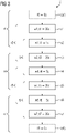
- figure 3 shows an exemplary sequence S, based on which the method 200 is to be run through as an example below.
- the sequence S includes steps s 1 -s 7 , each of which is assigned a tool w 1 -w 7 and a machining time t 1 -t 7 . From this, triples r 2 to r 6 can be formed.
- the first work step s 1 has no preceding work step and the last work step s 7 has no subsequent work step, so that, strictly speaking, no triples r 1 or r 7 can be formed.
- "empty" work steps s 0 and/or s 8 can be assumed, to which no tool 125 is assigned and whose processing time t is zero.
- a maximum cycle time of the tool magazine 110 is 18 s in this example.
- r 2 , r 4 and r 6 are critical, namely r 2 , r 4 and r 6 , whose processing times (5s each) are below the maximum cycle time (18s).
- the set M contains the three triples r 2 , r 4 and r 6 .
- the first critical triple r 2 concerns movements of the feeder with respect to the tools w 1 and w 3 .
- the relevance of the first critical triple r 2 is 4 (in the following tables, ÜP stands for the transfer point 130): triple promotion movement rides r2 w1 from ÜP to p1; w3 from p3 to ÜP p1 to p3 3 r4 w3 from ÜP to p3 - 1 r6 - - 0
- the second critical triple r 4 concerns movements of the feeder with respect to the tools w 3 and w 5 .
- the relevance of the second critical triple r 4 is 5: triple promotion movement rides r2 w3 from p3 to ÜP - 1 r4 w5 from p5 to ÜP; w3 from ÜP to p3; p3 to p5 3 r6 w5 from ÜP to p5 - 1
- the third critical triple r 6 concerns movements of the feeder with respect to the tools w 5 and w 7 .
- the relevance of the third critical triple r 6 is 4: triple promotion movement rides r2 - - - r4 w5 from p5 to ÜP; 1 r6 w5 from ÜP to p5; w7 from p7 to ÜP P5 to p7 3
- the critical triple r with the highest relevance is r 4 , so the tools w 3 and w 5 are each assigned a location 135, so that when r 4 is processed, one is possible short, ideally no waiting time for the machine tool 105 arises.
- the tools w 3 and w 5 can be placed at the two locations p 3 and p 5 with the smallest distance from the transfer point 135 .
- the second triple r 4 is removed from the set M.
- the relevance of the first critical triple r 2 is 2: triple promotion movement rides r2 w1 from ÜP to p1 p1 to p3 2 r4 - - 0 r6 - - 0
- the relevance of the third critical triple r 6 is 2: triple promotion movement rides r2 - - - r4 - - - r6 w5 from ÜP to p5 p5 to p7 2
- the tools w 1 and w 3 are placed in the tool magazine 110 in such a way that the waiting time for the machine tool 105 when processing r 2 is as short as possible, and ideally there is no waiting at all.
- the tools w 1 and w 3 are preferably placed at locations p 1 , p 3 close to the transfer point 130 . More preferably, locations p 1 , p 3 that are close together are selected in order to also minimize the duration of the empty run from p 1 to p 3 .
- the duration of an empty trip between two places 135 can be determined empirically, for example, and assigned to one or both places 135 . Alternatively, the duration of the empty run can be determined algorithmically on the basis of absolute or relative coordinates of the places 135.
- the first triple r 2 is removed from the set M, leaving only the third triple r 3 in the set M. This automatically has the highest relevance, so the tools w 5 and w 7 assigned to it are placed before the iterations end.
- all tools 125 that relate to at least one critical triple r are each assigned to a location 135 .
- Remaining tools w 2 , w 4 and w 6 can then be assigned to any locations 135 that are still free.
- step 215 the set M of all critical triples r i is determined.
- the triples with the highest relevance are selected one after the other and placed in the tool magazine 110 .
- the set M and the relevance function change after each placement.
- the algorithm terminates when the set M is empty or when no place is found for a selected triple r i .
- the selection function bad Max right ⁇ M rel right should favor the critical triples where the placement of the tools 125 has the greatest possible impact on the total wait time.
- the cycle times for as many additional critical triples r as possible are defined by the allocation of space to the tool or tools 125 of the triple that have not yet been placed. Only placements of the tools w to be moved are taken into account.
- the weight M,S (r') of r' is the weighted frequency with which the tool change r' occurs in the sequence S of work steps as a critical triple.
- the weight of r' is three if
- 2
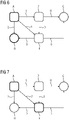
- Figures 4-7 each show a representation of a further example to explain the selection of a triple r from the set M.
- Five tools A, B, C, D and E are provided. If two tools AE are connected to one another by an arrow, the tools w 1 and w 3 to be moved form a critical triple r together with another tool w 2 (not shown). The arrow starts from the tool AE to be put away and ends at the tool AE to be fetched. A total of seven critical triples r are shown. Tools 125 that are not contained by a critical triple r are in figure 4 not shown. Tools AE that have already been assigned locations 135 are shown in circles; Tools AE that have not yet been assigned are shown in rounded squares.
- the tool w 1 used during the movements is not listed.
- pairs of places considered here are ordered and include places p i-1 and p i+1 . That pair of locations is selected which results in the shortest waiting time for the partial occupancy of the tool magazine 110 extended by this assignment. Instead of estimating the waiting time for the critical tool changes overlapping with r right ′ ⁇ M
- locations 135 for tools A and B are to be found. That is, during location selection, tools A and B are also used as placed considered.
- the tool triples (A, B), (A, D) and (B, C) are thus fully placed and their changeover time can be calculated when the locations for A and B are selected.
- For the partially placed triples (A,E) and (B,E) only the times for returning A and fetching B can be calculated.
- the triples (D, E) and (E, C) have no relation to the triple (A, B) to be placed and are not considered.
- a tool triple (w i-1 , w i w i+1 ) as ⁇ -critical if the processing time t of tool w i is less than the sum from ⁇ and the minimum cycle time of the not yet completely placed critical tool triple r.
- the space allocation heuristic can update the set M of critical tool triples r in each iteration.
- This set M can be replaced by the set of ⁇ -critical tool triples r.
- ⁇ is preferably chosen according to the distance between the minimum and maximum cycle time of the tool magazine 110 . A value of approximately 3 seconds for ⁇ has proven to be favorable for the tool magazine 110 considered as an example.
- the location allocation heuristic sequentially assigns tools 125 from critical triples r magazine locations 135 and thereby ensures that the corresponding occupancy of the magazine is permissible. After termination of the heuristic, it may be that the remaining tools 125 can no longer be accommodated in the tool magazine 110 in such a way that the tool magazine 110 is allowed to be occupied with all tools 125 . In particular in the case of full tool magazines 110 and tools 125 to which only a few specific locations 135 can be assigned, the partial occupancy of the magazine determined by the heuristic can often no longer be extended to a permissible full magazine occupancy. If the tool magazine 110 includes a shelf magazine, a large number of different tools 125 are usually to be placed in the tool magazine 110, so that the tool magazine 110 is usually filled to a high degree.
- the heuristic can already take into account the remaining tools 125 when determining the partial allocation. In other words, the heuristic can continue to successively place the critical tools 125, but at each placement guarantees that there is an allowable extension to full magazine occupancy.
- the supplementary occupancy serves the heuristic as a guarantee that the partial occupancy determined up to now can be extended to a permissible, complete occupancy of the tool magazine 110.
- the algorithm can have a permissible magazine occupancy for all tools in each iteration.
- the reconstruction of the guarantor should be resource-saving, since the heuristic calls it very frequently. Therefore, the reconstruction preferably takes place in a three-stage escalation scheme. If the reconstruction is not successful in one stage, an attempt can be made to achieve the reconstruction using the next stage. At each stage, the effort to achieve the reconstruction increases. If no stage is successful, an impermissible resource situation can be reported back.
- an attempt is made to determine the guarantor (supplementary assignment of the tool magazine 110) with minimal changes from the previous guarantor.
- the place assignment heuristic successively places a tool triplet r, where at least one of the tools of r has not yet assigned a final place; r ⁇ ⁇ ⁇ .
- Tool(s) r ⁇ can impermissibly overlap with tools 125 from the previous guarantor (without r ⁇ ) in their assigned locations 135 . If all tools 125 overlapping with r ⁇ (adjacent location consideration) are removed from the previous guarantor, then the reduced guarantor is permissible, but no longer complete. The removed tools 125 are now placed on the locations 135 previously used by r ⁇ in the guarantor. If this is not possible, the swap has failed.
- the previous locations of r ⁇ in the guarantor do not provide enough headroom to accommodate the intersecting tools 125. This can have various causes, for example because there is not enough space available due to the consideration of the adjacent location, or because not all overlapping tools 125 are permitted in the previous locations 135 of r - .
- the options for assigning new locations 135 for tools 125 from the guarantor are increased. Not only are the intersecting tools 125 removed, but all tools 125 from a suitable neighborhood, both at the newly assigned locations 135 and at the previous locations of r - in the guarantor.
- a suitable neighborhood is, for example, the entire column. the Removed Tools 125 are now re-placed for the Guarantor.
- the reconstruction algorithm outlined above first groups the tools 125 into groups of equivalent tools 125 in terms of their placement possibilities; the Tools 125 have the same footprint, the same allowed magazine locations, etc.
- the order in which tools 125 from a group are placed is irrelevant to the allowability.
- the groups are sorted according to their relative flexibility in terms of possible seat assignments. If, for example, there are only as many permissible locations 135 for a group as there are tools 125 in the group, then this group is maximally inflexible; only the exact location allocation can be permuted.
- the groups are preferably processed one after the other with increasing flexibility.
- places 135 are assigned to the tools 125 of the group. Particularly in the case of oversized tools 125 or tools 125 which, in addition to one or more positions 135, also take up one or more half positions 135, it is preferable to ensure good utilization of the positions 135.
- segments of connected places 135 of the tool magazine 110 can be determined.
- the places 135 can more preferably be selected according to a best-fit method.
- the tools 125, which each also occupy one or more half spaces 135 should be placed next to one another if possible, since two tools 125 can then half occupy a space 135 of the tool magazine 110 without colliding.
- the goal of this mixed integer program is to maximize the number of tools 125 placed. If the optimal objective function value is smaller than the number of tools to be newly placed 125, then there is no permissible one Seat allocation for all tools 125. In this case, the guarantor's reconstruction is considered to have failed and the seat selection is rejected as inadmissible due to the resource limitation.
- figure 8 shows an exemplary, concrete shelf magazine 110 with 251 magazine locations 135, on which the heuristic described here was tested as an example.
- the places 135 are distributed over 13 columns, of which only three columns 805 are permitted for particularly heavy tools 125.
- a right side 810 with eight magazine columns is the main side
- a left side 815 with five magazine columns is the opposite side.
- the feeder 115 For access to the opposite side 815, the feeder 115 must rotate about a vertical axis and, if necessary, rotate back again after the access.
- the coordinate axes shown are examples.
- the transfer point 130 for the machine tool 105 is located approximately halfway between the main side 810 and the opposite side 815 and is shown here on the coordinates (0, 0, 400).
- FIG figure 9 12 shows an exemplary initial arrangement of the tool magazine 110.
- FIG figure 8 For the sake of clarity, the tool magazine 110 is shown schematically in two dimensions, but true to scale on each side, with the main side 810 on the left and the opposite side on the right.
- the transfer point 130 for the feeder 115 is here at (0, 0). 815
- the numbers here each represent an identification number (ID) of a tool 125 set up at a position 135. If the number is shown in a circle with a double border, the tool 125 occurs in a critical tool triple r, otherwise the number has a single border. Connecting arrows mark the order of the tools 125 in a critical tool triple r. In the figures 9 and 10 wear all Tools w an identification number, which is marked with a prefix "#" in the following text.
- the algorithm preferably first determines the critical tool triples r from the given work steps s.
- One of the tool pairs w 1 , w 3 occurs in the critical triples r in both possible orders: (#101,#355), (#355, #101).
- the tool triple r with the highest relevance is placed, here the triple (#101, #355) with relevance 9.
- the relevances are updated and the next triple r with the highest relevance is placed.
- the triples (#203, #420), (#147, #399), (#420, #400), (#333, #340), (#494, #333) and (#355, # 101) is selected and a location 135 with a minimum changeover time is determined for the tool(s) 125 that have not yet been placed.
- figure 10 shows a final occupancy of the tool magazine 110 determined by the heuristic. It can be seen very clearly that the tools 125 from critical triples r are stored in places 135 close to the transfer point 130 if possible. However, tools #101, #399, and #494 can only be placed in the three middle columns 805 for heavy tools 125. For these tools 125, the tools 125 related to them in a critical triple are placed closer to the heavy tool 125 columns.
Landscapes
- Engineering & Computer Science (AREA)
- Manufacturing & Machinery (AREA)
- Physics & Mathematics (AREA)
- General Physics & Mathematics (AREA)
- Automation & Control Theory (AREA)
- Quality & Reliability (AREA)
- General Engineering & Computer Science (AREA)
- Mechanical Engineering (AREA)
- Geometry (AREA)
- Human Computer Interaction (AREA)
- Automatic Tool Replacement In Machine Tools (AREA)
- Multi-Process Working Machines And Systems (AREA)
- General Factory Administration (AREA)
Claims (13)
- Procédé (200) destiné à l'affectation d'outils wi à des emplacements pi dans un magasin d'outils (110) ; dans lequel le magasin d'outils (110) est conçu pour mettre un certain nombre d'outils wi à la disposition d'une machine-outil (105) ; dans lequel le magasin d'outils (110) comprend un dispositif de chargement (115) à des fins de transport d'outils wi ; dans lequel le procédé (200) comprend les étapes suivantes dans lesquelles :- on enregistre une séquence (S) d'étapes de travail planifiées si de la machine-outil (105) ;- dans lequel, à chaque étape de travail si, est attribué un outil wi avec lequel la machine-outil (105) met en œuvre l'étape de travail si, et un temps de traitement ti au cours duquel l'outil wi est utilisé par la machine-outil (105) ;o dans lequel, avant l'étape de travail si, le dispositif de chargement (115) transporte l'outil wi à partir de l'emplacement pi qui lui a été attribué dans le magasin d'outils (110) jusqu'à un point de livraison (130) ;o où il est récupéré par la machine-outil (105) ;o dans lequel, après l'étape de travail si, l'outil wi est déposé par la machine-outil (105) au point de livraison (130) ;o d'où il est transporté par le dispositif de chargement (115) jusqu'à l'emplacement pi qui lui a été attribué dans le magasin d'outils (110) ;- dans lequel, à chaque emplacement pi, est attribué un temps bi dont a besoin le dispositif de chargement (115) pour un transport d'un outil wi à partir de l'emplacement pi jusqu'au point de livraison (130) ou inversement ;caractérisé par les étapes suivantes dans lesquelles :- on détermine un temps de cycle maximal dont a besoin le dispositif de chargement (115) pour transporter un outil wi-1 d'une étape de travail si-1 qui a été mise en œuvre, à partir du point de livraison (130) jusqu'à l'emplacement pi-1 qui lui a été attribué, pour se déplacer à partir de cet endroit jusqu'à l'emplacement pi+1 de l'outil wi+1 d'une étape de travail suivante si+1, et pour transporter l'outil wi+1 à partir de cet endroit jusqu'au point de livraison (130) ;- on détermine une quantité M avec tous les triplets ri d'étapes opératoires qui se suivent l'une l'autre si-1, si, si+1, dans lesquelles le temps de traitement ti de l'étape de travail si est plus court que le temps de cycle maximal ;- (a) on détermine des pertinences des triplets ri de la quantité M ; dans lequel la pertinence d'un triplet ri comprend un nombre de mouvements ou de transports qui sont spécifiés lorsque l'outil wi-1 est affecté à un emplacement pi-1 et lorsque l'outil wi+1 est affecté à un emplacement Pi+i ;- (b) on détermine un triplet de la quantité M qui présente la pertinence la plus élevée ;- (c) on affecte, à un emplacement p1, l'outil w1 du triplet qui a été déterminé et/ou l'outil w3 à un emplacement pi d'une manière telle que le temps de traitement t2 est inférieur ou le moins supérieur possible à la somme des temps qui est requise pour le transport de l'outil w1 à partir du point de livraison (130) jusqu'à l'emplacement p1, pour le déplacement du dispositif de chargement (115) à partir de cet endroit jusqu'à l'emplacement p3, et pour le transport de l'outil w3 à partir de cet endroit jusqu'au point de livraison (130) ;- (d) on retire de la quantité M le triplet qui a été déterminé ;- on répète les étapes (a) à (d) jusqu'à ce que la quantité M soit vide ; et- on affecte des outils wi qui n'ont pas fait l'objet d'une affectation à des emplacements pi du magasin d'outils (110), qui n'ont pas fait l'objet d'une affectation.
- Procédé (200) selon la revendication 1, dans lequel la pertinence n'est déterminée que par rapport à des étapes de travail si qui sont incluses dans un triplet ri de la quantité M.
- Procédé (200) selon la revendication 1 ou 2, dans lequel, à chaque emplacement pi est attribué un premier temps bi1 dont a besoin le dispositif de chargement (115) pour un transport d'un outil wi à partir de l'emplacement pi jusqu'au point de livraison (130) et un deuxième temps bi2 dont a besoin le dispositif de chargement (115) pour un transport d'un outil wi à partir du point de livraison (130) jusqu'à l'emplacement pi ; et dans lequel les deux temps sont pris en compte dans l'étape (c).
- Procédé (200) selon l'une quelconque des revendications précédentes, dans lequel le temps bi d'un emplacement pi est également déterminé par rapport à un outil wi qui a été affecté à l'emplacement pi.
- Procédé (200) selon l'une quelconque des revendications précédentes, dans lequel une affectation à l'étape (c) a lieu d'une manière telle que, par la suite, tous les outils (125) qui n'ont pas fait l'objet d'une affectation peuvent être affectés à un emplacement autorisé (135).
- Procédé (200) selon la revendication 5, dans lequel, à l'étape (c), on ne procède à une affectation que lorsqu'on peut obtenir une garantie qui inclut une affectation autorisée, à des emplacements libres, de tous les outils (125) qui n'ont pas fait l'objet d'une affectation.
- Procédé (200) selon la revendication 6, dans lequel la détermination de la garantie englobe un échange d'outils (125) qui ont été affectés à des emplacements dans la garantie.
- Procédé (200) selon la revendication 6 ou 7, dans lequel la détermination de la garantie comprend une affectation d'outils (125) à des emplacements (135) au moyen d'une stratégie de l'ajustement optimal.
- Procédé (200) selon les revendications 6 à 8, dans lequel la détermination de la garantie comprend une affectation d'outils (125) à des emplacements (135) au moyen d'une programmation en numération mixte.
- Procédé (200) selon les revendications 6 à 9, dans lequel la garantie est déterminée en conformité avec la revendication 8, au cas où sa détermination en conformité avec la revendication 7 échoue ; et est déterminée en conformité avec la revendication 9, au cas où sa détermination en conformité avec la revendication 8 échoue.
- Dispositif (140) destiné à l'affectation d'outils (125) à des emplacements (135) dans un magasin d'outils (110) ; dans lequel le dispositif (140) est conçu pour la mise en œuvre d'un procédé (200) selon l'une quelconque des revendications précédentes.
- Dispositif (140) selon la revendication 11, dans lequel le dispositif est conçu pour la commande d'un transport d'outils (125), qui sont requis pour le traitement de la séquence (S), à des emplacements (135) qui ont été attribués.
- Système (100) qui comprend une machine-outil (105) et un dispositif (140) selon la revendication 11 ou 12 ; dans lequel le dispositif (140) est conçu pour commander la machine-outil (105) à des fins de mise en œuvre des étapes de travail de la séquence (S).
Applications Claiming Priority (1)
| Application Number | Priority Date | Filing Date | Title |
|---|---|---|---|
| PCT/EP2019/055121 WO2020177836A1 (fr) | 2019-03-01 | 2019-03-01 | Affectation d'outils à des emplacements dans un magasin d'outils |
Publications (2)
| Publication Number | Publication Date |
|---|---|
| EP3914976A1 EP3914976A1 (fr) | 2021-12-01 |
| EP3914976B1 true EP3914976B1 (fr) | 2022-10-12 |
Family
ID=65729310
Family Applications (1)
| Application Number | Title | Priority Date | Filing Date |
|---|---|---|---|
| EP19710332.8A Active EP3914976B1 (fr) | 2019-03-01 | 2019-03-01 | Affectation d'outils à des emplacements dans un magasin d'outils |
Country Status (4)
| Country | Link |
|---|---|
| US (1) | US12204320B2 (fr) |
| EP (1) | EP3914976B1 (fr) |
| CN (1) | CN113728281B (fr) |
| WO (1) | WO2020177836A1 (fr) |
Families Citing this family (4)
| Publication number | Priority date | Publication date | Assignee | Title |
|---|---|---|---|---|
| EP3929680A1 (fr) * | 2020-06-24 | 2021-12-29 | Siemens Sanayi ve Ticaret A. S. | Procédé de fabrication d'une pièce de travail avec une séquence optimale de machines-outils par une machine de fabrication commandée par ordinateur et machine correspondante |
| DE102021207741A1 (de) * | 2021-07-20 | 2023-01-26 | KyooBe Tech GmbH | Produktionsanlage und Verfahren zur Herstellung eines Produkts |
| IT202100027455A1 (it) * | 2021-10-26 | 2023-04-26 | Scm Group Spa | Metodo di disposizione di utensili in un magazzino e centro di lavoro che implementa tale metodo. |
| CN119511938B (zh) * | 2024-11-18 | 2025-05-23 | 南兴装备股份有限公司 | 基于改进贪心算法的工件钻孔动作优化方法及系统 |
Family Cites Families (9)
| Publication number | Priority date | Publication date | Assignee | Title |
|---|---|---|---|---|
| US6665580B1 (en) * | 2000-09-18 | 2003-12-16 | Thermwood Corporation | Automatic cutting tool management system for a computer numeric controlled machining system |
| DE102006028970A1 (de) * | 2006-06-19 | 2007-12-20 | Stama Maschinenfabrik Gmbh | Verfahren und Vorrichtung zum Bearbeiten eines Werkstücks, insbesondere zum spanabhebenden Bearbeiten eines metallischen Werkstücks |
| JP4203539B1 (ja) * | 2008-07-01 | 2009-01-07 | 株式会社松浦機械製作所 | 工具交換システム |
| DE102010047287B4 (de) * | 2010-09-27 | 2014-04-10 | Stama Maschinenfabrik Gmbh | Verfahren zum Bearbeiten eines Werkstücks |
| DE102011088055A1 (de) * | 2011-12-08 | 2013-06-13 | Deckel Maho Pfronten Gmbh | System und Verfahren zum Bereitstellen von Werkzeugen an einer Werkzeugmaschine, sowie Werkzeugmaschine mit einem Werkzeugwechselsystem |
| CN202540003U (zh) * | 2011-12-31 | 2012-11-21 | 上海三一精机有限公司 | 用于自动化生产线的刀库集中管理系统 |
| DE102012111230A1 (de) * | 2012-11-21 | 2014-05-22 | Mag Ias Gmbh | Verfahren zur Steuerung von Werkzeugwechselvorgängen und Werkzeugmaschine |
| US9840010B2 (en) * | 2015-01-20 | 2017-12-12 | The Boeing Company | Tool changer |
| AT519561B1 (de) * | 2017-04-25 | 2018-08-15 | Fill Gmbh | Bearbeitungsanlage und Verfahren zum Durchführen eines Werkzeugwechsels an der Bearbeitungsanlage |
-
2019
- 2019-03-01 EP EP19710332.8A patent/EP3914976B1/fr active Active
- 2019-03-01 WO PCT/EP2019/055121 patent/WO2020177836A1/fr not_active Ceased
- 2019-03-01 CN CN201980095983.2A patent/CN113728281B/zh not_active Expired - Fee Related
- 2019-03-01 US US17/435,180 patent/US12204320B2/en active Active
Also Published As
| Publication number | Publication date |
|---|---|
| EP3914976A1 (fr) | 2021-12-01 |
| US20220147024A1 (en) | 2022-05-12 |
| US12204320B2 (en) | 2025-01-21 |
| WO2020177836A1 (fr) | 2020-09-10 |
| CN113728281A (zh) | 2021-11-30 |
| CN113728281B (zh) | 2024-08-13 |
Similar Documents
| Publication | Publication Date | Title |
|---|---|---|
| EP3914976B1 (fr) | Affectation d'outils à des emplacements dans un magasin d'outils | |
| DE69028612T2 (de) | Aufstelloptimierung von flexiblen Herstellungssystemen | |
| EP3180969B1 (fr) | Équipement de cartes à circuit imprimé | |
| EP2829166B1 (fr) | Formation de groupes d'installation sur des lignes de placement | |
| EP3511126A1 (fr) | Procédé de planification assistée par ordinateur d'un flux de travail exécutable à l'aide d'un robot | |
| DE102012103830A1 (de) | Verfahren und system zur automatischen verhinderung von gegenseitiger blockierung in mehrfachrobotersystemen | |
| DE1524103A1 (de) | Datenverarbeitungsanlage | |
| EP3225086B1 (fr) | Procédé et installation d'un système de controle pour équiper des cartes de circuits imprimés | |
| WO2014079601A1 (fr) | Optimisation de familles d'équipement | |
| EP3661694B1 (fr) | Procédé et dispositif pour l'optimisation assistée par ordinateur d'une occupation d'emplacements de magasin par des outils dans au moins un magasin d'outils pour une machine-outil | |
| EP3485455A1 (fr) | Procédé et dispositif de détermination de tailles de lots optimales | |
| EP3381249B1 (fr) | Procédé assisté par ordinateur et dispositif d'attribution de modules à des lignes de placement | |
| WO2020057713A1 (fr) | Procédé et dispositif d'optimisation assistée par ordinateur d'un transport d'outils pour au moins un magasin d'outils présentant un certain nombre d'emplacements de magasin | |
| WO2014079600A1 (fr) | Optimisation de familles d'équipement | |
| EP4204181B1 (fr) | Procédé d'optimisation assistée par ordinateur d'opérations de transport d'outils pour au moins un magasin d'outils comportant un certain nombre d'espaces de magasin | |
| DE69926798T2 (de) | Verfahren zum synchronisieren eines substratbehandlungssystems | |
| EP3908424B1 (fr) | Procédé d'optimisation, assistée par ordinateur, d'une occupation d'emplacements de magasin par des outils | |
| EP4228385B1 (fr) | Procédé mis en oeuvre par ordinateur de détermination d'une affectation optimale des types de module à une ligne de montage sélectionnée en fonction de son performance de montage | |
| WO2017152979A1 (fr) | Procédé et dispositif d'attribution de modules à des lignes de placement | |
| EP4498303A1 (fr) | Procédé de génération d'un plan de fourniture d'au moins un outil pour au moins une machine de production, produit programme informatique, support de stockage lisible par ordinateur et dispositif informatique | |
| WO2023151885A1 (fr) | Procédé mis en oeuvre par ordinateur pour déterminer au moins une famille d'équipements fixes de types de cartes de circuits imprimés pour un nombre prédéterminé d'une pluralité de groupes d'une ou de plusieurs lignes d'assemblage | |
| EP3914977B1 (fr) | Procédé et dispositif d'optimisation assistée par ordinateur d'une occupation d'emplacements de magasinage par des outils | |
| EP4309477B1 (fr) | Procédé et dispositif de commande pour identifier au moins une installation fixe pour une ligne de montage | |
| EP4458116B1 (fr) | Procédé mis en oeuvre par ordinateur destiné à la détermination d'une quantité partielle de types de module d'une quantité déterminée de types de module et d'une armure fixe modifiée associée | |
| EP4730107A1 (fr) | Procédé et dispositif de planification de mémoire pour la génération d'un code de programme pour calculer un réseau neuronal artificiel dans un environnement matériel |
Legal Events
| Date | Code | Title | Description |
|---|---|---|---|
| STAA | Information on the status of an ep patent application or granted ep patent |
Free format text: STATUS: UNKNOWN |
|
| STAA | Information on the status of an ep patent application or granted ep patent |
Free format text: STATUS: THE INTERNATIONAL PUBLICATION HAS BEEN MADE |
|
| PUAI | Public reference made under article 153(3) epc to a published international application that has entered the european phase |
Free format text: ORIGINAL CODE: 0009012 |
|
| STAA | Information on the status of an ep patent application or granted ep patent |
Free format text: STATUS: REQUEST FOR EXAMINATION WAS MADE |
|
| 17P | Request for examination filed |
Effective date: 20210827 |
|
| AK | Designated contracting states |
Kind code of ref document: A1 Designated state(s): AL AT BE BG CH CY CZ DE DK EE ES FI FR GB GR HR HU IE IS IT LI LT LU LV MC MK MT NL NO PL PT RO RS SE SI SK SM TR |
|
| DAV | Request for validation of the european patent (deleted) | ||
| DAX | Request for extension of the european patent (deleted) | ||
| GRAP | Despatch of communication of intention to grant a patent |
Free format text: ORIGINAL CODE: EPIDOSNIGR1 |
|
| STAA | Information on the status of an ep patent application or granted ep patent |
Free format text: STATUS: GRANT OF PATENT IS INTENDED |
|
| INTG | Intention to grant announced |
Effective date: 20220613 |
|
| GRAS | Grant fee paid |
Free format text: ORIGINAL CODE: EPIDOSNIGR3 |
|
| GRAA | (expected) grant |
Free format text: ORIGINAL CODE: 0009210 |
|
| STAA | Information on the status of an ep patent application or granted ep patent |
Free format text: STATUS: THE PATENT HAS BEEN GRANTED |
|
| AK | Designated contracting states |
Kind code of ref document: B1 Designated state(s): AL AT BE BG CH CY CZ DE DK EE ES FI FR GB GR HR HU IE IS IT LI LT LU LV MC MK MT NL NO PL PT RO RS SE SI SK SM TR |
|
| REG | Reference to a national code |
Ref country code: GB Ref legal event code: FG4D Free format text: NOT ENGLISH |
|
| REG | Reference to a national code |
Ref country code: CH Ref legal event code: EP |
|
| REG | Reference to a national code |
Ref country code: DE Ref legal event code: R096 Ref document number: 502019005895 Country of ref document: DE |
|
| REG | Reference to a national code |
Ref country code: IE Ref legal event code: FG4D Free format text: LANGUAGE OF EP DOCUMENT: GERMAN |
|
| REG | Reference to a national code |
Ref country code: AT Ref legal event code: REF Ref document number: 1524535 Country of ref document: AT Kind code of ref document: T Effective date: 20221115 |
|
| REG | Reference to a national code |
Ref country code: LT Ref legal event code: MG9D |
|
| REG | Reference to a national code |
Ref country code: NL Ref legal event code: MP Effective date: 20221012 |
|
| PG25 | Lapsed in a contracting state [announced via postgrant information from national office to epo] |
Ref country code: NL Free format text: LAPSE BECAUSE OF FAILURE TO SUBMIT A TRANSLATION OF THE DESCRIPTION OR TO PAY THE FEE WITHIN THE PRESCRIBED TIME-LIMIT Effective date: 20221012 |
|
| PG25 | Lapsed in a contracting state [announced via postgrant information from national office to epo] |
Ref country code: SE Free format text: LAPSE BECAUSE OF FAILURE TO SUBMIT A TRANSLATION OF THE DESCRIPTION OR TO PAY THE FEE WITHIN THE PRESCRIBED TIME-LIMIT Effective date: 20221012 Ref country code: PT Free format text: LAPSE BECAUSE OF FAILURE TO SUBMIT A TRANSLATION OF THE DESCRIPTION OR TO PAY THE FEE WITHIN THE PRESCRIBED TIME-LIMIT Effective date: 20230213 Ref country code: NO Free format text: LAPSE BECAUSE OF FAILURE TO SUBMIT A TRANSLATION OF THE DESCRIPTION OR TO PAY THE FEE WITHIN THE PRESCRIBED TIME-LIMIT Effective date: 20230112 Ref country code: LT Free format text: LAPSE BECAUSE OF FAILURE TO SUBMIT A TRANSLATION OF THE DESCRIPTION OR TO PAY THE FEE WITHIN THE PRESCRIBED TIME-LIMIT Effective date: 20221012 Ref country code: FI Free format text: LAPSE BECAUSE OF FAILURE TO SUBMIT A TRANSLATION OF THE DESCRIPTION OR TO PAY THE FEE WITHIN THE PRESCRIBED TIME-LIMIT Effective date: 20221012 Ref country code: ES Free format text: LAPSE BECAUSE OF FAILURE TO SUBMIT A TRANSLATION OF THE DESCRIPTION OR TO PAY THE FEE WITHIN THE PRESCRIBED TIME-LIMIT Effective date: 20221012 |
|
| PG25 | Lapsed in a contracting state [announced via postgrant information from national office to epo] |
Ref country code: RS Free format text: LAPSE BECAUSE OF FAILURE TO SUBMIT A TRANSLATION OF THE DESCRIPTION OR TO PAY THE FEE WITHIN THE PRESCRIBED TIME-LIMIT Effective date: 20221012 Ref country code: PL Free format text: LAPSE BECAUSE OF FAILURE TO SUBMIT A TRANSLATION OF THE DESCRIPTION OR TO PAY THE FEE WITHIN THE PRESCRIBED TIME-LIMIT Effective date: 20221012 Ref country code: LV Free format text: LAPSE BECAUSE OF FAILURE TO SUBMIT A TRANSLATION OF THE DESCRIPTION OR TO PAY THE FEE WITHIN THE PRESCRIBED TIME-LIMIT Effective date: 20221012 Ref country code: IS Free format text: LAPSE BECAUSE OF FAILURE TO SUBMIT A TRANSLATION OF THE DESCRIPTION OR TO PAY THE FEE WITHIN THE PRESCRIBED TIME-LIMIT Effective date: 20230212 Ref country code: HR Free format text: LAPSE BECAUSE OF FAILURE TO SUBMIT A TRANSLATION OF THE DESCRIPTION OR TO PAY THE FEE WITHIN THE PRESCRIBED TIME-LIMIT Effective date: 20221012 Ref country code: GR Free format text: LAPSE BECAUSE OF FAILURE TO SUBMIT A TRANSLATION OF THE DESCRIPTION OR TO PAY THE FEE WITHIN THE PRESCRIBED TIME-LIMIT Effective date: 20230113 |
|
| REG | Reference to a national code |
Ref country code: DE Ref legal event code: R097 Ref document number: 502019005895 Country of ref document: DE |
|
| PG25 | Lapsed in a contracting state [announced via postgrant information from national office to epo] |
Ref country code: SM Free format text: LAPSE BECAUSE OF FAILURE TO SUBMIT A TRANSLATION OF THE DESCRIPTION OR TO PAY THE FEE WITHIN THE PRESCRIBED TIME-LIMIT Effective date: 20221012 Ref country code: RO Free format text: LAPSE BECAUSE OF FAILURE TO SUBMIT A TRANSLATION OF THE DESCRIPTION OR TO PAY THE FEE WITHIN THE PRESCRIBED TIME-LIMIT Effective date: 20221012 Ref country code: EE Free format text: LAPSE BECAUSE OF FAILURE TO SUBMIT A TRANSLATION OF THE DESCRIPTION OR TO PAY THE FEE WITHIN THE PRESCRIBED TIME-LIMIT Effective date: 20221012 Ref country code: DK Free format text: LAPSE BECAUSE OF FAILURE TO SUBMIT A TRANSLATION OF THE DESCRIPTION OR TO PAY THE FEE WITHIN THE PRESCRIBED TIME-LIMIT Effective date: 20221012 Ref country code: CZ Free format text: LAPSE BECAUSE OF FAILURE TO SUBMIT A TRANSLATION OF THE DESCRIPTION OR TO PAY THE FEE WITHIN THE PRESCRIBED TIME-LIMIT Effective date: 20221012 |
|
| PLBE | No opposition filed within time limit |
Free format text: ORIGINAL CODE: 0009261 |
|
| STAA | Information on the status of an ep patent application or granted ep patent |
Free format text: STATUS: NO OPPOSITION FILED WITHIN TIME LIMIT |
|
| PG25 | Lapsed in a contracting state [announced via postgrant information from national office to epo] |
Ref country code: SK Free format text: LAPSE BECAUSE OF FAILURE TO SUBMIT A TRANSLATION OF THE DESCRIPTION OR TO PAY THE FEE WITHIN THE PRESCRIBED TIME-LIMIT Effective date: 20221012 Ref country code: AL Free format text: LAPSE BECAUSE OF FAILURE TO SUBMIT A TRANSLATION OF THE DESCRIPTION OR TO PAY THE FEE WITHIN THE PRESCRIBED TIME-LIMIT Effective date: 20221012 |
|
| 26N | No opposition filed |
Effective date: 20230713 |
|
| PG25 | Lapsed in a contracting state [announced via postgrant information from national office to epo] |
Ref country code: MC Free format text: LAPSE BECAUSE OF FAILURE TO SUBMIT A TRANSLATION OF THE DESCRIPTION OR TO PAY THE FEE WITHIN THE PRESCRIBED TIME-LIMIT Effective date: 20221012 |
|
| REG | Reference to a national code |
Ref country code: CH Ref legal event code: PL |
|
| GBPC | Gb: european patent ceased through non-payment of renewal fee |
Effective date: 20230301 |
|
| PG25 | Lapsed in a contracting state [announced via postgrant information from national office to epo] |
Ref country code: SI Free format text: LAPSE BECAUSE OF FAILURE TO SUBMIT A TRANSLATION OF THE DESCRIPTION OR TO PAY THE FEE WITHIN THE PRESCRIBED TIME-LIMIT Effective date: 20221012 |
|
| REG | Reference to a national code |
Ref country code: BE Ref legal event code: MM Effective date: 20230331 |
|
| PG25 | Lapsed in a contracting state [announced via postgrant information from national office to epo] |
Ref country code: LU Free format text: LAPSE BECAUSE OF NON-PAYMENT OF DUE FEES Effective date: 20230301 |
|
| REG | Reference to a national code |
Ref country code: IE Ref legal event code: MM4A |
|
| PG25 | Lapsed in a contracting state [announced via postgrant information from national office to epo] |
Ref country code: GB Free format text: LAPSE BECAUSE OF NON-PAYMENT OF DUE FEES Effective date: 20230301 |
|
| PG25 | Lapsed in a contracting state [announced via postgrant information from national office to epo] |
Ref country code: LI Free format text: LAPSE BECAUSE OF NON-PAYMENT OF DUE FEES Effective date: 20230331 Ref country code: IE Free format text: LAPSE BECAUSE OF NON-PAYMENT OF DUE FEES Effective date: 20230301 Ref country code: GB Free format text: LAPSE BECAUSE OF NON-PAYMENT OF DUE FEES Effective date: 20230301 Ref country code: CH Free format text: LAPSE BECAUSE OF NON-PAYMENT OF DUE FEES Effective date: 20230331 |
|
| PG25 | Lapsed in a contracting state [announced via postgrant information from national office to epo] |
Ref country code: BE Free format text: LAPSE BECAUSE OF NON-PAYMENT OF DUE FEES Effective date: 20230331 |
|
| PGFP | Annual fee paid to national office [announced via postgrant information from national office to epo] |
Ref country code: IT Payment date: 20240321 Year of fee payment: 6 Ref country code: FR Payment date: 20240319 Year of fee payment: 6 |
|
| PGFP | Annual fee paid to national office [announced via postgrant information from national office to epo] |
Ref country code: DE Payment date: 20240517 Year of fee payment: 6 |
|
| PG25 | Lapsed in a contracting state [announced via postgrant information from national office to epo] |
Ref country code: BG Free format text: LAPSE BECAUSE OF FAILURE TO SUBMIT A TRANSLATION OF THE DESCRIPTION OR TO PAY THE FEE WITHIN THE PRESCRIBED TIME-LIMIT Effective date: 20221012 |
|
| PG25 | Lapsed in a contracting state [announced via postgrant information from national office to epo] |
Ref country code: BG Free format text: LAPSE BECAUSE OF FAILURE TO SUBMIT A TRANSLATION OF THE DESCRIPTION OR TO PAY THE FEE WITHIN THE PRESCRIBED TIME-LIMIT Effective date: 20221012 |
|
| REG | Reference to a national code |
Ref country code: AT Ref legal event code: MM01 Ref document number: 1524535 Country of ref document: AT Kind code of ref document: T Effective date: 20240301 |
|
| PG25 | Lapsed in a contracting state [announced via postgrant information from national office to epo] |
Ref country code: AT Free format text: LAPSE BECAUSE OF NON-PAYMENT OF DUE FEES Effective date: 20240301 |
|
| PG25 | Lapsed in a contracting state [announced via postgrant information from national office to epo] |
Ref country code: CY Free format text: LAPSE BECAUSE OF FAILURE TO SUBMIT A TRANSLATION OF THE DESCRIPTION OR TO PAY THE FEE WITHIN THE PRESCRIBED TIME-LIMIT; INVALID AB INITIO Effective date: 20190301 |
|
| PG25 | Lapsed in a contracting state [announced via postgrant information from national office to epo] |
Ref country code: HU Free format text: LAPSE BECAUSE OF FAILURE TO SUBMIT A TRANSLATION OF THE DESCRIPTION OR TO PAY THE FEE WITHIN THE PRESCRIBED TIME-LIMIT; INVALID AB INITIO Effective date: 20190301 |
|
| REG | Reference to a national code |
Ref country code: DE Ref legal event code: R119 Ref document number: 502019005895 Country of ref document: DE |
|
| PG25 | Lapsed in a contracting state [announced via postgrant information from national office to epo] |
Ref country code: TR Free format text: LAPSE BECAUSE OF FAILURE TO SUBMIT A TRANSLATION OF THE DESCRIPTION OR TO PAY THE FEE WITHIN THE PRESCRIBED TIME-LIMIT Effective date: 20221012 |
|
| PG25 | Lapsed in a contracting state [announced via postgrant information from national office to epo] |
Ref country code: DE Free format text: LAPSE BECAUSE OF NON-PAYMENT OF DUE FEES Effective date: 20251001 |
|
| PG25 | Lapsed in a contracting state [announced via postgrant information from national office to epo] |
Ref country code: IT Free format text: LAPSE BECAUSE OF NON-PAYMENT OF DUE FEES Effective date: 20250301 Ref country code: FR Free format text: LAPSE BECAUSE OF NON-PAYMENT OF DUE FEES Effective date: 20250331 |
|
| PGFP | Annual fee paid to national office [announced via postgrant information from national office to epo] |
Ref country code: AT Payment date: 20260410 Year of fee payment: 5 |