EP3915512A1 - Système prothétique dentaire modulaire - Google Patents
Système prothétique dentaire modulaire Download PDFInfo
- Publication number
- EP3915512A1 EP3915512A1 EP20176489.1A EP20176489A EP3915512A1 EP 3915512 A1 EP3915512 A1 EP 3915512A1 EP 20176489 A EP20176489 A EP 20176489A EP 3915512 A1 EP3915512 A1 EP 3915512A1
- Authority
- EP
- European Patent Office
- Prior art keywords
- modules
- dental prosthesis
- retention field
- prosthesis system
- module
- Prior art date
- Legal status (The legal status is an assumption and is not a legal conclusion. Google has not performed a legal analysis and makes no representation as to the accuracy of the status listed.)
- Withdrawn
Links
Images


Classifications
-
- A—HUMAN NECESSITIES
- A61—MEDICAL OR VETERINARY SCIENCE; HYGIENE
- A61C—DENTISTRY; APPARATUS OR METHODS FOR ORAL OR DENTAL HYGIENE
- A61C13/00—Dental prostheses; Making same
- A61C13/225—Fastening prostheses in the mouth
- A61C13/26—Dentures without palates; Partial dentures, e.g. bridges
-
- A—HUMAN NECESSITIES
- A61—MEDICAL OR VETERINARY SCIENCE; HYGIENE
- A61C—DENTISTRY; APPARATUS OR METHODS FOR ORAL OR DENTAL HYGIENE
- A61C13/00—Dental prostheses; Making same
- A61C13/0003—Making bridge-work, inlays, implants or the like
-
- A—HUMAN NECESSITIES
- A61—MEDICAL OR VETERINARY SCIENCE; HYGIENE
- A61C—DENTISTRY; APPARATUS OR METHODS FOR ORAL OR DENTAL HYGIENE
- A61C13/00—Dental prostheses; Making same
- A61C13/225—Fastening prostheses in the mouth
-
- A—HUMAN NECESSITIES
- A61—MEDICAL OR VETERINARY SCIENCE; HYGIENE
- A61C—DENTISTRY; APPARATUS OR METHODS FOR ORAL OR DENTAL HYGIENE
- A61C13/00—Dental prostheses; Making same
- A61C13/225—Fastening prostheses in the mouth
- A61C13/267—Clasp fastening
-
- A—HUMAN NECESSITIES
- A61—MEDICAL OR VETERINARY SCIENCE; HYGIENE
- A61C—DENTISTRY; APPARATUS OR METHODS FOR ORAL OR DENTAL HYGIENE
- A61C5/00—Filling or capping teeth
- A61C5/70—Tooth crowns; Making thereof
Definitions
- the invention relates to a dental prosthesis system, having at least one prosthesis base module, in particular an upper jaw plate or a lower jaw bracket, one or more retention field modules for connection to dentures and / or one or more fastener modules for fastening the dental prosthesis system to the remaining teeth of a patient.
- the invention also relates to a method for producing and / or expanding a dental prosthesis system.
- the field of prosthetic and removable dentures includes partial and full dentures as well as their manufacture and fitting into the oral cavity of a patient.
- Partial dentures also known as partial dentures, only replace part of the teeth and can be attached to the patient's remaining teeth.
- a simple version of a partial prosthesis comprises a so-called prosthesis base, made of plastic or metal, which adapts to the patient's palate as a plate or bracket. Common designs are the so-called upper jaw plate and the lower jaw bracket.
- Fastening means but also retention fields are connected to the prosthesis base.
- the fastening means mostly so-called brackets, which grip around a tooth and / or supports which rest on a tooth, are used to fasten and support one or more teeth of the remaining teeth of the patient.
- the retention fields lie on the alveolar ridge and form a type of reinforcement or armouring for the dental prosthesis.
- the artificial teeth and the prosthetic saddle surrounding the alveolar ridge are usually cast from plastic by the dental technician into the retention fields that serve as reinforcement.
- such partial prostheses are usually produced as a one-piece model cast prosthesis in the dental laboratory from plastic or metal.
- the prosthesis base is connected in one piece with clips and retention panels.
- the model cast prostheses are first modeled by hand from precast wax parts or created with 3D software and then plotted by a 3D printer.
- the models are embedded in investment material and melted out.
- the cavities in the investment material that are created after melting or burning out are then filled with a model casting alloy, such as a chromium-cobalt-molybdenum alloy. Then the investment material and sprue pins are removed and the model casting is sandblasted, electrolytically polished, fitted and polished to a high gloss.
- such a model cast prosthesis can also be milled out of a stainless steel block, but there are height differences of up to 30 mm between the brackets and the lowest point, e.g. the roof of the mouth. Therefore, 30 mm high stainless steel brackets are required in order to be able to completely mill out the model cast prosthesis.
- a palatal plate only has a wall thickness of 0.30 mm - 1.00 mm, such processes would result in a very uneconomical ratio with a material loss of approx. 95% and extremely high tool wear during CAD-CAM processing.
- digital manufacturing methods such as the well-known SLM technology (selective laser melting) are used nowadays.
- SLM technology selective laser melting
- the model casting prosthesis is carefully fitted onto the plaster model and all possible sources of error, such as incorrect impressions by the dentist, scanning errors, defective plaster expansions, defective investment mixes, investment errors due to air inclusions - including cavities and oxidation of the alloys - as well as errors due to milling tool wear, distortions of the 3D printed ones Plastic constructions or sintered constructions etc. are balanced by the dental technician by hand by laborious grinding of the model cast prosthesis.
- the model cast prosthesis is pressed repeatedly onto the sensitive plaster model until it, without tilting and with a Accuracy of approx. 0.01 mm fits the plaster model. However, if the plaster model is damaged in the process, sufficient accuracy can no longer be achieved.
- the insertion axis is the axial direction along which the partial prosthesis is inserted into the patient's oral cavity.
- undercut depths of fasteners such as brackets and the equatorial plane of the remaining teeth must be taken into account, with the axis of insertion being perpendicular to the equatorial plane of the remaining teeth.
- a computer-aided method for planning a repair or adaptation of a partial prosthesis is known in which the axis of insertion is determined using a digital 3D model of the jaw and the prosthesis.
- brackets and supports have to be ground out and the model cast base has to be laboriously reworked.
- An extension is also often not economically viable, for example if new brackets, supports and / or retention fields for new plastic teeth would have to be soldered on in a laborious manner.
- the high heat generated during soldering also means that the plastic teeth that are already present in the model cast prosthesis have to be removed and re-incorporated later. In these cases, the only option is an expensive new production.
- a device for dental prostheses or for tooth regulation, in which wire-shaped fastening elements are produced individually and cast into a part that rests on the gums and / or the palate and is made of cast resin, is from the DE 44 20 044 A1 known.
- the US 5,102,337 B1 also provides for individually prefabricating brackets from a thermoplastic and adhering them to the partial denture using a quick-drying adhesive.
- a plug-in system for connecting individual components of model cast prostheses is in the DE 41 38 975 A1 disclosed.
- the individual components of the model cast prosthesis, which are provided with pairs of holes, are separated from one another positioned in the patient's mouth or on the plaster model.
- a similar dental prosthesis milled from pieces is from the DE 10 2014 104 456 A1 known.
- the sections are first milled out of a milling block and then connected to one another in a materially bonded manner, in particular glued, welded or soldered.
- the disadvantage of the known connections between the prosthesis base and the connecting elements is that they are non-detachable connections and the model cast prosthesis can only be expanded or repaired, as already described, by laborious grinding and soldering.
- the prosthesis frame has a bow-shaped connector made from a chromium-cobalt-molybdenum compound.
- the connector is placed in the mold and the anchoring part, for example a crown and the dental prosthesis part, ie the prosthesis framework or the prosthesis base, are poured directly onto the connector, but the materials should not form a material bond with one another.
- the connector itself is prefabricated with a connection element and with a connection for the prosthesis framework, the connection element having ready-made fitting surfaces for a positive fit with the crown and the prosthesis framework being cast onto the connection.
- the connector has a first connecting element, an assigned second connecting element sits on the crown, the connecting elements are designed as attachments, bolts, screws or the like to form the detachable connecting device.
- the object is achieved by a dental prosthesis system according to claim 1.
- a dental prosthesis system is characterized in that the at least one prosthesis base module, the one or more retention field modules and the one or more fastener modules are modularly designed as separate individual modules and each have alignment elements in a position and position predetermined by these alignment elements / or position are aligned or alignable in such a way that the prosthesis system can be inserted into the remaining teeth of the patient and attached to it along an insertion axis, in particular undercut depths and / or the equatorial plane of the remaining teeth.
- the invention therefore provides for the necessary components of a dental prosthesis to be designed modularly, each as individual modules, and to specify a position, for example an angle, and / or position, for example premolar 15, molar 26, incisive 11, etc., of the individual modules to one another by means of alignment means So that the individual modules aligned with one another in this position and / or position jointly form a dental prosthesis that can be inserted into the remaining teeth of the patient along a possible insertion axis, particularly taking into account the equatorial plane and undercut depths, and can be attached to it.
- the use of alignment means enables the individual modules to be produced separately from one another or separately and then to align them with one another with a common insertion axis.
- the term remaining payment is not limited exclusively to the patient's natural teeth, but also includes implants and / or crowns that are already are firmly integrated into the bit or can only be integrated at a later point in time.
- the production of the individual modules can be carried out according to known methods, e.g. B. by casting, by selective laser sintering, but also in a CAD-CAM milling process or 3D printing.
- B. by casting, by selective laser sintering, but also in a CAD-CAM milling process or 3D printing.
- the latter manufacturing method there is a particular advantage that the total height of the milling block can be reduced considerably, in particular by approx. 50% compared to a non-modular manufacture, since the individual modules are not already arranged in the intended position and / or position when they are milled out must be.
- it is also conceivable to mill one type of individual modules e.g.
- the insertion axis can be determined using methods known to those skilled in the art, for example manually on the physical working model with the aid of a parallelometer or with the aid of software, e.g. by creating a virtual working model.
- the alignment means can then be designed on the basis of the determined insertion axis in such a way that the individual modules can be aligned with one another by means of the alignment elements in the position and / or position corresponding to the insertion axis.
- the insertion axis takes into account the entire remaining teeth, crowns and implants of the dentition in order to define precise undercuts at the respective tooth equator.
- the solution according to the invention provides a dental prosthesis system which, due to shorter machine production times and lower material costs, can be machine-produced at low cost.
- the workload and the difficulty of the adjustments to be made for the dental technician can also be reduced considerably thanks to the modular structure, which is why the manufacturing costs are further reduced.
- the modular structure also enables the dental prosthesis system z. B. by the dentist directly on the patient adapt. Furthermore, the continuously occurring tensions, which are caused by the production z. B. a model cast base or due to the brackets and / or supports can be avoided, so that a tension-free seated denture is guaranteed when the patient is incorporated.
- the one or more retention field modules can have at least one retention field for connection to the dental prosthesis and / or the one or more fastening means modules can have at least one fastening means for fastening the dental prosthesis system to the remaining teeth of a patient.
- the one or more retention field modules and the one or more fastening means modules are each formed in one piece with the at least one retention field or the at least one fastening means.
- a retention field module in one piece with a retention field, which serves as reinforcement or reinforcement for the dental prosthesis
- a fastening means module in one piece with a fastening means, e.g. a bracket for gripping a tooth and / or a support for supporting on a tooth surface and / or to cast or mill a counter bearing bracket.
- the one or more retention field modules have both at least one retention field for connection to the dental prosthesis and at least one fastening means for fastening the dental prosthesis system to the remaining teeth of the patient.
- the total number of individual modules can be reduced by designing a retention field module which, in addition to the retention field, also has a fastening means. This is also particularly advantageous at positions in the patient's mouth that have relatively little space available for the dental prosthesis. According to another embodiment of the invention, it is also conceivable to design the prosthesis base module itself with a retention field.
- the aligning means each have an insert part and a complementary guide receptacle, the insert part being guided by the guide receptacle into an end position and received there.
- the slide-in part and the guide receptacle are designed, in particular in one piece, on a single module each and together form a rail-like guide that moves the two single modules into a fixed end position.
- the two individual modules are in the intended position and / or position with respect to one another, so that the prosthesis system formed from the entirety of all individual modules can be fastened along the previously established and / or determined insertion axis in the remaining dentition of the patient.
- the respective slide-in parts are preferably designed to be geometrically identical; the desired end position for alignment in the intended position and / or position is predetermined by the geometry of the guide receptacle.
- the insert part within the Guide receptacle is mounted in the end position with a bearing play, in particular with a bearing play in a range between 0.01 mm and 5.0 mm.
- the natural teeth are also not rigidly anchored in the jawbone, but also have a certain amount of play in order to be able to better absorb and compensate for forces and loads that occur during chewing.
- This natural tooth play can expediently be reproduced with a bearing play between the insert part and the guide receptacle.
- the bearing play can be filled with an elastic material, in particular silicone, before the fastening means is attached.
- the bearing play serves to compensate for the inaccuracies and tolerances that occur in the different manufacturing processes.
- the at least one prosthesis base module and / or the one or more retention field modules and / or the one or more fastening means modules each have at least one insert part and at least one retention field module has one or more guide receptacles.
- the guide receptacles are formed exclusively on the retention field modules, the retention fields of which rest on the patient's alveolar ridge.
- the prosthesis base module which adapts to the palate, and the fastener modules designed with fastening means, e.g. with clips and / or supports, each have at least one insert part and can be inserted into the guide receptacles of the retention field modules for the desired alignment along the insertion axis.
- the retention fields or retention field modules running along the alveolar ridge can form a reference or the starting point for aligning the individual modules of the prosthesis system.
- guide receptacles can alternatively also be provided on the prosthesis base module and / or on the fastening means modules.
- the one or more fastener modules can then be used indirectly via a retention field or via a Retention field module connected or connectable to the prosthesis base module.
- a connection means is provided, via which the at least one prosthesis base module, the one or more retention field modules and the one or more fastening means modules are detachably connected to one another or are connectable.
- the dental prosthesis system can, for. B. in the event of loss of a remaining tooth intended for attachment and / or damage, can be expanded or repaired at will and with little effort by a "replacement module".
- a replacement module For example, it is conceivable to replace a fastener module with a retention field module as a basis for the dental prosthesis that has become necessary at this point if the associated remaining tooth is lost.
- an insert part of the replacement module is inserted into a guide receptacle of an adjacent individual module, e.g. B. an adjacent retention field module introduced.
- the digital processing systems e.g. CAD-CAM, SLM or 3D printer
- CAD-CAM CAD-CAM
- SLM 3D printer
- the desired fasteners with insert parts and guide mounts including all retention areas for new denture teeth as required.
- the usual work processes can be retained using prefabricated insert parts, guide mounts and / or retention areas.
- the connecting means comprises a pourable and moldable plastic, in particular a flowable cold polymer.
- the connecting means can be poured around or into the individual modules aligned with one another by the aligning means, whereby a form-fitting, but not a material-to-material connection is created when solidifying. It is particularly advantageous here that the connecting means can also be used to form the tooth replacement in the same work step; in other words, according to a particularly useful variant of the invention, the tooth replacement, in particular the prosthesis saddle, can be cast in one and the same work step together and in one piece with the connecting means.
- a connecting means cast in this way between the at least one prosthesis base module, the one or more retention field modules and the one or more fastening means modules can be released in an advantageous further development of this variant of the invention by heating the connecting means.
- the connecting means changes into a soft or flexible state, which makes it possible to remove the alignment means, in particular an insert part of an individual module, from a guide receptacle "pull out” another single module without damage and replace the single module with another single module, a replacement module.
- Only the connecting means is "softened” for this purpose, so that the alignment means remain undamaged and with unchanged geometry, whereby an alignment along the insertion axis, including the replacement module, is guaranteed during repair and / or expansion of the dental prosthesis.
- the temperature required to heat the connecting means is much lower than, for. B. when soldering, so that damage to the location of the temperature effect of further spaced dentures by the action of heat is avoided.
- the alignment means in particular an insert part of the alignment means, has two materials, in particular the materials have spring hardnesses and / or color properties and / or melting properties that differ from one another.
- the insert part or fastening means is preferably designed in two parts.
- a highest possible contact pressure of the fastening means from one of the insert parts or fastening means, consisting z. B. from a chromium-cobalt-molybdenum alloy to generate.
- the visible section of the insert part and the fastening means in the anterior region can be made of, for example, white or tooth-colored high-performance plastic or high-performance ceramic or gold.
- a hybrid slide-in part and / or hybrid fastening means are examples of a hybrid slide-in part and / or hybrid fastening means.
- high-performance ceramic fastening means can advantageously be soldered with glass solder in a standard dental furnace without the prosthesis base modules warping or oxidizing.
- This variant is also based on the advantage that, for the first time, higher spring stiffnesses are only set in the slide-in part, for example by hardening processes without warping or oxidizing the denture base module again. Due to the extremely small amount of material of the two-part slide-in parts as well as guide receptacles and / or fastening means, material costs are almost irrelevant, even with gold.
- the alignment means in particular an insert part of the alignment means, and / or the fastening means has a spring force means.
- the spring force module preferably serves as a spring arm for the fastening means, so that its contact pressure on a residual tooth or an implant or a crown of the patient when inserting and removing the prosthesis, which is usually necessary several times a day, especially for cleaning, is evenly distributed over the entire clamp contact surface . This allows the abrasion on the remaining tooth / implant / crown, also caused by chewing movements, to be significantly reduced and the holding force to be increased.
- bracket tip In the case of fasteners designed as brackets, as are known in the art, the contact pressure acting on the remaining tooth is usually concentrated on only a small section of a bracket arm, the so-called bracket tip, the contact surface of which rests on the remaining tooth below the tooth equator.
- bracket tip When inserting the prosthesis, only these clip tips have a small amount of movement in order to be able to push the fastening means over the tooth equator.
- the remaining areas of the bracket are rigid. This leads to selective abrasion due to the relatively small contact surface or friction surface of the clasp tip on the remaining tooth, which in the long term causes considerable damage to the tooth-holding apparatus.
- this variant of the invention is therefore particularly advantageous if the fastening means is designed as a clip and its fastening arm and / or an insert part adjoining the fastening arm is provided with the spring force means, the spring force means comprising a spring slot and a spring bore, the geometry of which defines the desired spring stiffness.
- the spring force means comprising a spring slot and a spring bore, the geometry of which defines the desired spring stiffness.
- a first clamp arm and a second Clamp arm designed to be resiliently movable with respect to one another by the spring force means, in particular the spring slot and the spring bore, whereby in particular the contact pressure can be evenly distributed over the entire bearing surface.
- the first clamp arm and the second clamp arm can preferably be “sprung open” like pliers in the tooth equatorial plane when the dental prosthesis is inserted and removed, thus minimizing abrasion.
- the object set out at the beginning is also achieved by a method for producing and / or expanding a dental prosthesis system according to claim 13.
- such a method is characterized in that, in a first method step, the individual modules forming the dental prosthesis system, at least one prosthesis base module, in particular an upper jaw plate or a lower jaw bracket, one or more retention field modules for connection to dentures and / or one or more fastener modules for fastening the dental prosthesis system to the remaining teeth, in particular also on non-existent, plannable implants and / or crowns, of a patient.
- the individual modules forming the dental prosthesis system at least one prosthesis base module, in particular an upper jaw plate or a lower jaw bracket, one or more retention field modules for connection to dentures and / or one or more fastener modules for fastening the dental prosthesis system to the remaining teeth, in particular also on non-existent, plannable implants and / or crowns, of a patient.
- the dental prosthesis system should include at least one prosthesis base module and a retention field module with a retention field and fastening means or, alternatively, at least one prosthesis base module, a retention field module with a retention field and a fastening means module with fastening means.
- a possible insertion axis along which the dental prosthesis system can be inserted into the remaining teeth of the patient and can be fastened to it is determined.
- the insertion axis can also be determined manually or with the aid of software using known methods. For example, a possible insertion axis is determined either by software or by assembling the individual parts on the plaster model or in the patient's teeth. The determined insertion axis also results in an alignment of the individual modules, i.e. H. their position and / or position to one another.
- a model cast prosthesis also known as a clasp prosthesis, can be expanded into an implant-supported denture for the first time.
- An implant-supported dental prosthesis is a dental prosthesis, in particular a prosthetic dental prosthesis that is attached to implants.
- the position and / or position of the at least one prosthesis base module, of the one or more retention field modules and of the one or more fastening means modules relative to one another, corresponding to the insertion axis, is specified in each case by means of alignment means.
- the at least one prosthesis base module, the one or more retention field modules and the one or more fastener modules are preferably made according to one of the methods known from the prior art, either with a digital processing system (e.g. CAD-CAM, SLM or 3D printer) or manually manufactured, in particular milled or cast. It is particularly advantageous if the alignment means are also produced in one piece and thus at the same time as the corresponding individual modules.
- the individual modules aligned in the position and / or position corresponding to the insertion axis and predetermined by the alignment means, the at least one prosthesis base module, the one or more retention field modules and the one or more fastening means modules are releasably connected to one another by means of a connecting means.
- the connecting means comprises a plastic that can be cast and molded, in particular a flowable cold polymer and is cast to connect the at least one prosthesis base module, the one or more retention field modules and the one or more fastener modules and at the same time to form the dental prosthesis.
- the connecting means therefore advantageously comprises the same material as the dental prosthesis, so that both the connecting means and the dental prosthesis can be cast at the same time in a single work step.
- one or more replacement modules intended for expansion and / or replacement such as basic prosthesis modules and / or retention field modules and / or fastener modules, are provided, their position and / or position with respect to one another and with respect to the other individual modules, such as basic prosthesis modules and / or retention field modules and / or fastening means modules are determined on the basis of an insertion axis and specified by alignment means.
- any replacement modules can be provided directly in the first process step in the planning and definition of the original individual modules forming the dental prosthesis and their position and / or position can be specified according to the axis of insertion by means of the alignment means.
- This primarily applies to individual modules to be replaced in the event of a defect or damage, which are preferably replaced by an identical replacement module.
- extensions that z. B. if a natural tooth used for anchoring is lost, a further retention field for connection to a tooth replacement replacing the tooth can be provided directly in the process step.
- the z. B. due to the failure of a natural tooth changed jaw and palate geometry of the patient determined or checked again or a new axis of insertion can be determined.
- the connection between the at least one prosthesis base module, the one or the multiple retention field modules and / or the one or more fastener modules released by heating and the at least one prosthesis base module, the one or more retention field modules and / or the one or more fastener modules by one or more prosthesis base modules intended for expansion or replacement and / or retention field modules and / or fastener modules module are exchanged.
- the connecting means By heating the connecting means, in particular locally, it can be converted into a soft or flexible state, which enables the alignment means, in particular an insert part of an individual module, to be "pulled out” without damage from a guide receptacle of another individual module.
- the removed single module can then be replaced by an identical or a different single module, a replacement module.
- Only the connecting means is "softened” for this purpose, so that the alignment means remain undamaged and with unchanged geometry, whereby an alignment along the insertion axis, including the replacement module, is guaranteed during repair and / or expansion of the dental prosthesis system.
- the temperature required to heat the connecting means is much lower than, for. B. during soldering, so that damage to the tooth replacement, which is further apart from the location of the temperature effect, is avoided by the effect of heat.
- a locally limited heating of the connecting means can advantageously be realized via the fastening means itself, in particular a clamp, which is designed as an electrical resistor and is heated by applying a current. In this way, only the area of the directly adjacent connecting means is softened, whereby the alignment means can be removed, but deformations in other areas of the connecting means are prevented.
- the local heating can also be done with soldering iron pliers or a hydrogen torch.
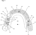
- Figure 1 shows a schematic top view of an exemplary embodiment of a dental prosthesis system 100 according to the invention, which is shown attached to an exemplary remaining tooth 200 of a patient.
- the remaining teeth 200 are part of the lower jaw, with two teeth for anchoring the dental prosthesis system 100 being shown in the left molar region.
- the dental prosthesis system 100 comprises a prosthesis base module 110 and three retention field modules 120, which are each designed as individual modules separately from one another.
- the basic prosthesis module 110 hugs the patient's palate and is designed here as a lower jaw bow.
- the retention field modules 120 each have a retention field 121, here in the form of a perforated plate, which rests on the ridge of the patient and forms a type of reinforcement or armouring for the dental prosthesis and the prosthesis saddle.
- the retention field module 120 assigned to the remaining teeth 200 in the left molar region also has two fastening means 131, each of which can be fastened to the remaining teeth 200 of the patient and shown fastened here, with which it is preferably designed in one piece.
- the fastening means 131 here each comprise a clamp 131 which engages around the remaining teeth 200 and a support 133 which is supported on a tooth surface 211 of the remaining teeth 200.
- a fastening means 131 can also comprise no, two or more clamps 132 and / or no, two or more supports 133.
- the individual modules, in this embodiment the prosthesis base module 110 and the three retention field modules 120 each have alignment means 140, which the prosthesis base module 110 and the three retention field modules 120 in one Align the predetermined position and / or position to one another, which corresponds to the insertion axis z of the dental prosthesis system 100.
- the insertion axis z is determined on the basis of the equatorial plane and the undercut depths of the remaining teeth 200 and is shown in FIG Figure 1 shown as an example pointing vertically into the plane of the drawing.
- An alignment means 140 each comprises an insert part 141 and a complementary guide receptacle 142.
- the insert part 141 is formed, in particular in one piece, on an individual module and the guide receptacle 142, in particular in one piece, on another individual module, the insert part 141 and the guide receptacle 142 with one another form a rail-like guide, which the two individual modules transfer to a defined end position so that they are aligned with one another in the intended position and / or position.
- the insert parts 141 can also each have a retention field 121.
- the prosthesis base module 110 is connected in one piece with a total of four insert parts 141.
- the retention field module 120 associated with the remaining teeth 200 has two guide receptacles 142, which are received for the guided reception of two associated, complementary insert parts 141 of the basic prosthesis module 100.
- the retention field module 120 assigned to the incisor region has a guide receptacle 142 for the guided reception of a complementary insert part 141 of the basic prosthesis module 110 and an insert part 141 which is received in a guided manner by a complementary guide receptacle 142 of the remaining retention field module 120 allocated to the right molar region.
- this retention field module 120 also has a guide receptacle 142 for the guided reception of a complementarily arranged insert part 141 of the prosthesis base module 100.
- the alignment means 140 are shown here in the end position that specifies the intended position and / or position, ie the insert parts 141 are each completely pushed into the guide receptacles 142 assigned to them.
- a bearing play 143 in a range between 0.01 mm and 5.0 mm, which imitates the natural tooth play of the teeth rooted in the jawbone, is provided between the insert part 141 and the guide receptacle 142.
- the inaccuracies and tolerances caused by the different manufacturing processes can be compensated for.
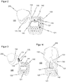
- FIG Figure 2 A schematic perspective side view of an exemplary embodiment of a dental prosthesis system 100 according to the invention is shown in FIG Figure 2 shown.
- a retention field module 120 and a fastening means module 130 are shown which, for example, form a dental prosthesis system 100 with a prosthesis base module 110 (not shown here).
- the fastening means module 130 is shown fastened to a remaining tooth 200 of a patient with a fastening means 131, here by way of example a clamp 132.
- the clip 132 is connected to an insert part 141 via a fastening arm 134; the clip 132, fastening arm 134 and insert part 141 are preferably formed in one piece.
- the insert part 141 has a particularly uncomplicated, cuboid basic shape, but can alternatively also be designed in other suitable geometric shapes.
- the insert part 141 is also provided with a retention field 121.
- the insert part 141 forms the alignment means 140.
- the guide receptacle 142 is part of the retention field module 120 and is preferably arranged in one piece on the upper side of its retention field 121, ie on the side facing away from the alveolar ridge when the prosthesis system 100 is inserted.
- the guide receptacle is shown open at the top, ie on the side facing away from the retention area 121.
- Insertion part 141 and guide receptacle 142 lie loosely one inside the other in a completely inserted end position, whereby the fastening means module 130 and the retention field module 120 are aligned in the intended position and / or position corresponding to the insertion axis z.
- a bearing play 143 in a range of 0.01 mm to 5.00 mm is again provided in order to compensate, for example, the inaccuracies and tolerances caused by different manufacturing processes.
- FIG. 3 shows a schematic perspective side view of a very similar exemplary embodiment of a dental prosthesis system according to the invention 100 with a retention field module 120 and a fastener module 130.
- the fastening means module 130 has a two-part fastening means 131, also referred to as a hybrid fastening means, a first part comprising a fastening means arm 134 and a second part comprising a bracket 132.
- the two-part design makes it possible to design the fastening means 131 to include two different materials.
- the two materials can have spring hardnesses and / or color properties and / or melting properties that differ from one another.
- the two parts of the fastening means 131 can, for example, be aligned with one another via a plug connection 135 and connected to one another by means of a connecting means 150, which is not visible here.
- Figure 4 shows a schematic top view of an exemplary embodiment of the invention of a dental prosthesis system 100 with a two-part fastening means module 130, in which both the fastening means 131, in particular the clip 132, and the alignment means 140, in particular the insert part 141, are designed in two parts.
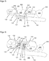
- FIG. 5 a schematic side view of an exemplary embodiment of a prosthesis system 100 according to the invention is shown in a basic version.
- the partial section of the prosthesis system 100 shown here comprises a retention field module 120 and two fastener modules 130.
- the retention field module 120 in addition to the retention field 121, also includes a lower jaw bow or is designed in one piece with the prosthesis base module 110.
- the prosthesis base module 110 it is also conceivable for the prosthesis base module 110 to be designed as a separate individual module or for the prosthesis base module 110 to have a retention area 121 connected in one piece.
- two guide receptacles 142 are formed in the cuboid shape already described.
- An insert part 141 is seated in each of the guide receptacles 142 (see plan view from FIG Figure 6 ) of the respective fastening means module 130.
- Each guide receptacle 142 with the insert part 141 arranged therein together form alignment means 140.
- the two fastening means modules 130 are attached to the Remaining teeth 200 of the patient attached, one of the fastening means modules 130 being attached to a first tooth 210 and the other being attached to a third tooth 230 of the remaining teeth 200.
- a fourth tooth 240 of the remaining teeth 200 is shown adjacent to the third tooth 230.
- the patient's second tooth which was originally located between the first tooth 210 and the third tooth 230, has already failed and is being replaced by the tooth replacement 300 indicated by dashed lines.
- a second replacement tooth 320 together with the prosthesis saddle 350 of the dental prosthesis 300, is therefore cast into the retention field 121, which acts as a reinforcement or reinforcement.
- the second replacement tooth 320 and the prosthesis saddle 350 act as connecting means 150 in order to connect the retention field module 120 to the two fastening means modules 130 in the position and / or position aligned by the alignment means 140.
- the exemplary embodiment of the prosthesis system 100 according to the invention is shown in a schematic plan view. Compared to the Figure 5 the broken line representation of the dental prosthesis 300 is dispensed with.
- the cuboidal design of the guide receptacle 142 of the alignment means 140 which is open upwards, ie in the direction of the tooth surface 211, as a result of which the respectively associated slide-in part 141 can be inserted from above.
- the bearing play 143 between the guide receptacle 142 and the insert part 141 lies in a range between 0.01 mm and 5.0 mm.
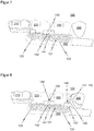
- the exemplary embodiment of a dental prosthesis system 100 according to the invention according to FIG Figure 5 is in the Figure 7 shown in a first optional expansion version.
- the extension version also takes into account the loss of the patient's third tooth 230, which now also has to be replaced with the aid of the prosthesis system 100.
- the modular structure of the dental prosthesis system 100 enables the fastening means module 130 originally attached to the third tooth 230 to be replaced by a replacement module, in this case a retention field module 120 with a retention field 121.
- the replacement module has an insert part that engages complementarily into the guide receptacle 142 of the adjacently arranged retention field module 120 141 on or is formed integrally therewith.
- the connecting means 150 is released, for example by heating it.
- the fastener module 130 can then be pulled out of the guide receptacle 142 and replaced by the replacement module designed as a retention field module 120.
- a third replacement tooth 330 and the associated section of the prosthetic saddle 350 are then cast into the retention field 121 of the replacement module, whereby the connecting means 150 is formed again at the same time.
- a retention field module 120 with a retention field 121 an insert part 141 which, together with the guide receptacle 142 of the adjacently arranged retention field module 120 of the prosthesis system 100, forms an alignment means 140, which is additionally designed with a guide receptacle 142, can be provided as the first replacement module.
- This guide receptacle 142 in turn forms an alignment means 140 with an insert part 141 of a second replacement module, namely a fastening means module 130, which has a bracket 132 as fastening means 131 for fastening to the previously unused fourth tooth 240.
- the modules are exchanged as described above.
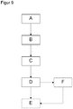
- the Figure 9 shows a flowchart of an exemplary sequence of the method according to the invention for producing and / or expanding an exemplary embodiment of a dental prosthesis system 100 according to the invention. The method shown is discussed below using the exemplary embodiments according to the figures described above.
- a prosthesis base module 110 in particular an upper jaw plate or a lower jaw bracket, as well as three retention field modules 120 with retention fields 121 for connection to dentures 300 and partly additionally with fastening means 131 for fastening the dental prosthesis system 131 to the remaining teeth 200 of a patient.
- a virtual or physical model of the Oral situation ie the jaw and palate geometry as well as the remaining teeth 200 of the patient are created and a possible insertion axis z along which the dental prosthesis system 100 can be inserted into the remaining teeth 200 of the patient and can be attached to it is determined in a second method step B on the basis of the model.
- the position and / or position of the basic prosthesis module 110 and of the retention field modules 120 corresponding to the insertion axis z is specified in a third method step C by means of alignment means 140 (see also FIG Figure 1 ).
- a fourth method step D the individual modules aligned in the position and / or position corresponding to the insertion axis z and predetermined by the alignment means 140, for example according to FIG Figure 5 a retention field module 120 with an integrated lower jaw bracket, as well as two fastening means modules 130 releasably connected to one another by means of a connecting means 150.
- the connecting means 150 comprises a cast and moldable plastic, in particular a flowable cold polymer, and is cast to connect the individual modules and also in method step D to form the dental prosthesis 300.
- one or more replacement modules suitable for expansion and / or replacement are optionally already installed in method step A or in an optional method step F, according to FIG Figure 8
- a retention field module 120 and a fastener module 130 are provided, whose position and / or position to one another and to the other individual modules is determined either on the basis of the originally determined insertion axis z or on the basis of a newly determined insertion axis z and is specified by the alignment means 140.
- connection between the individual modules can be released in a fifth method step E by heating the connecting means 150 and an individual module, according to FIG Figure 7 a Fastener module 130 by the corresponding replacement module, according to FIG Figure 7 a retention field module 120 can be replaced.
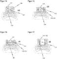
- the Figures 10 and 11 each show a schematic top view of a third or fourth exemplary embodiment of a dental prosthesis system 100 according to the invention, each of which is a lower jaw bracket ( Figure 10 ) or as a jaw plate ( Figure 11 ) formed prosthesis base module 110 with two integrally adjoining slide-in parts 141.
- the alignment of the insert parts 141 is directed in the direction of the alveolar ridge.
- the prosthesis system 100 further comprises a retention field module 120 with two guide receptacles 142 complementary to the insert parts 141 as well as a retention field 121 and two fastening means 131 Figure 11
- the insert parts 141 can also be inserted appropriately into a respective guide receptacle 142 of two individual retention field modules 120.
- the two individual retention field modules 120 each have a retention field 121 and a fastening means 131.
- FIG Figure 12 A schematic top view of a first exemplary embodiment of an alignment means 140 for a dental prosthesis system 100 according to the invention is shown in FIG Figure 12 shown, an associated sectional view shows the Figure 13 .
- the alignment means 140 is basically designed in the already described cuboid geometry that is open at the top.
- the guide receptacle 142 connected to the retention field 121 of the retention field module 120 comprises retaining means 144, which form an anchoring and additional guide for the insert part 141 of the fastening means module 130 that can be pushed into the guide receptacle 142 at the side.
- FIG Figure 14 A similar embodiment of an alignment means 140 with retaining means 144 is shown in FIG Figure 14 refer to.
- the retaining means 144 are designed in one piece, both on the insert part 141 and on the guide receptacle 142, to interlock in a complementary manner.
- the Figures 15 to 17 each show a schematic partial section in side view of exemplary embodiments of a connecting means 150 for a dental prosthesis system 100 according to the invention.
- the connecting means 150 can basically according to the connections known from the prior art, such as special adhesives, lasers, soldering, matrix and patrix attachment connections as well as grid and slide-in systems or connections based on adhesion and friction forces, such as those made according to the known telescope and conical crown principle be.
- the insert parts 141 of the Figures 14 to 17 are each interspersed with exemplary configurations of retention fields 121.
- a detachable connection between the guide receptacle 142 and the insert part 141 is implemented by a connecting means 150 designed as two bolts 151 running parallel to the direction of insertion of the insert part 141 into the guide receptacle 142.
- the connecting means 150 is formed by a single bolt 151 extending orthogonally to the direction of insertion
- the Figure 17 shows a T-bolt-like insert part 141 as a connecting means 150.
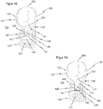
- FIG. 18 and 19 each shows a schematic top view of a first and a second exemplary embodiment of a spring force means 145 provided on the alignment means 140, more precisely on the insertion part 141 of the alignment means 140.
- the spring force means 145 comprises a spring slot 146 which extends along the insertion part 141 of the fastening means 131 designed as a bracket 132 or its fastening means arm 134 and a first bracket arm 136 and a second bracket arm 137 parallel to one another in the tooth equatorial plane of the remaining tooth 200 and / or a plane resiliently mounted to the tooth equatorial plane.
- a spring bore 147 is formed at one end of the spring slot 146.
- the geometry of the spring slot 146, in particular its length and the spring bore 147, in particular its diameter, but also the positioning of the spring bore 147 and the resulting wall thickness of the insert part 141 are used to set the spring stiffness.
- the bearing play 143 between the insertion part 141 and the guide receptacle 142 is filled with silicone before the connecting means 150 is attached. In this way, for example, a mobility of the insert part 141 within the guide receptacle 142 within the framework of the bearing play 143 on the one hand, and on the other hand, the push-in part 141 and the clamp arms 136, 137 can be spread open.
- the first exemplary embodiment shown has a single spring force means 145 with a spring slot 146 and a spring bore 147, as a result of which the first clamp arm 136 is essentially movably mounted, in particular so as to be resiliently expandable.
- two spring force means 145 with a respective spring slot 146 and spring bore 147 can be provided in order to mount both the first clamp arm 136 and the second clamp arm 137 movably, in particular so as to be resiliently expandable.
- the holding force can advantageously be increased and at the same time the abrasion of the remaining teeth 200 can be reduced by a more even distribution of the contact pressure over a larger area of the contact surface of the clamp arms 136, 137.
Landscapes
- Health & Medical Sciences (AREA)
- Oral & Maxillofacial Surgery (AREA)
- Dentistry (AREA)
- Epidemiology (AREA)
- Life Sciences & Earth Sciences (AREA)
- Animal Behavior & Ethology (AREA)
- General Health & Medical Sciences (AREA)
- Public Health (AREA)
- Veterinary Medicine (AREA)
- Dental Prosthetics (AREA)
Priority Applications (1)
| Application Number | Priority Date | Filing Date | Title |
|---|---|---|---|
| EP20176489.1A EP3915512A1 (fr) | 2020-05-26 | 2020-05-26 | Système prothétique dentaire modulaire |
Applications Claiming Priority (1)
| Application Number | Priority Date | Filing Date | Title |
|---|---|---|---|
| EP20176489.1A EP3915512A1 (fr) | 2020-05-26 | 2020-05-26 | Système prothétique dentaire modulaire |
Publications (1)
| Publication Number | Publication Date |
|---|---|
| EP3915512A1 true EP3915512A1 (fr) | 2021-12-01 |
Family
ID=70857059
Family Applications (1)
| Application Number | Title | Priority Date | Filing Date |
|---|---|---|---|
| EP20176489.1A Withdrawn EP3915512A1 (fr) | 2020-05-26 | 2020-05-26 | Système prothétique dentaire modulaire |
Country Status (1)
| Country | Link |
|---|---|
| EP (1) | EP3915512A1 (fr) |
Citations (12)
| Publication number | Priority date | Publication date | Assignee | Title |
|---|---|---|---|---|
| US2002048A (en) * | 1932-10-15 | 1935-05-21 | Cecil A Thomas | Extensible temporary bridge |
| US4163318A (en) * | 1977-03-21 | 1979-08-07 | Pasquale Tigani | Device for replacing missing teeth in human dentition |
| US4431415A (en) * | 1982-04-08 | 1984-02-14 | Pasquale Tigani | Device for replacing missing teeth in human dentition |
| EP0347574A2 (fr) | 1988-06-18 | 1989-12-27 | Peter Brehm | Méthode pour la fabrication d'une prothèse dentaire se composant d'un élément d'ancrage et d'un élément prothétique fixe audit élément d'ancrage, ainsi qu'une pièce de connexion pour la réalisation de ladite méthode |
| US5102337A (en) | 1990-01-16 | 1992-04-07 | Sol Soroca | Prefabricated thermoplastic clasp |
| DE4138975A1 (de) | 1991-11-27 | 1993-06-09 | Olaf 3400 Goettingen De Schmerling | Stecksystem zum verbund von bestandteilen von modellgussprothesen |
| DE4420044A1 (de) | 1993-06-09 | 1994-12-15 | Helmut Purner | Vorrichtung zum Zahnersatz, der Zahnregulierung oder dergleichen zahnmedizinische Behandlung |
| AT400099B (de) * | 1993-06-09 | 1995-09-25 | Purner Helmut | Abnehmbarer zahnersatz |
| US20110207080A1 (en) * | 2008-10-30 | 2011-08-25 | Dynadent Sarl | Dental device for temporarily filling the toothless gap following the extraction of a tooth and method for using said device |
| WO2011152643A2 (fr) * | 2010-05-31 | 2011-12-08 | Park Nam Hyo | Prothèse temporaire |
| DE102014104456A1 (de) | 2014-03-13 | 2015-09-17 | Amann Girrbach Ag | Verfahren zur Herstellung zumindest eines Teilstücks einer Zahnprothese |
| EP3324879B1 (fr) | 2015-07-21 | 2019-07-10 | Sirona Dental Systems GmbH | Planification d'un réparation ou ajustage d'une prothèse dentaire partielle |
-
2020
- 2020-05-26 EP EP20176489.1A patent/EP3915512A1/fr not_active Withdrawn
Patent Citations (12)
| Publication number | Priority date | Publication date | Assignee | Title |
|---|---|---|---|---|
| US2002048A (en) * | 1932-10-15 | 1935-05-21 | Cecil A Thomas | Extensible temporary bridge |
| US4163318A (en) * | 1977-03-21 | 1979-08-07 | Pasquale Tigani | Device for replacing missing teeth in human dentition |
| US4431415A (en) * | 1982-04-08 | 1984-02-14 | Pasquale Tigani | Device for replacing missing teeth in human dentition |
| EP0347574A2 (fr) | 1988-06-18 | 1989-12-27 | Peter Brehm | Méthode pour la fabrication d'une prothèse dentaire se composant d'un élément d'ancrage et d'un élément prothétique fixe audit élément d'ancrage, ainsi qu'une pièce de connexion pour la réalisation de ladite méthode |
| US5102337A (en) | 1990-01-16 | 1992-04-07 | Sol Soroca | Prefabricated thermoplastic clasp |
| DE4138975A1 (de) | 1991-11-27 | 1993-06-09 | Olaf 3400 Goettingen De Schmerling | Stecksystem zum verbund von bestandteilen von modellgussprothesen |
| DE4420044A1 (de) | 1993-06-09 | 1994-12-15 | Helmut Purner | Vorrichtung zum Zahnersatz, der Zahnregulierung oder dergleichen zahnmedizinische Behandlung |
| AT400099B (de) * | 1993-06-09 | 1995-09-25 | Purner Helmut | Abnehmbarer zahnersatz |
| US20110207080A1 (en) * | 2008-10-30 | 2011-08-25 | Dynadent Sarl | Dental device for temporarily filling the toothless gap following the extraction of a tooth and method for using said device |
| WO2011152643A2 (fr) * | 2010-05-31 | 2011-12-08 | Park Nam Hyo | Prothèse temporaire |
| DE102014104456A1 (de) | 2014-03-13 | 2015-09-17 | Amann Girrbach Ag | Verfahren zur Herstellung zumindest eines Teilstücks einer Zahnprothese |
| EP3324879B1 (fr) | 2015-07-21 | 2019-07-10 | Sirona Dental Systems GmbH | Planification d'un réparation ou ajustage d'une prothèse dentaire partielle |
Similar Documents
| Publication | Publication Date | Title |
|---|---|---|
| EP3229724B1 (fr) | Procédé pour fabriquer une prothèse dentaire avec un gabarit | |
| DE102007036549B4 (de) | Kieferorthopädische Vorrichtungs-Setzlehre, Satz aus Setzlehren-Kombinationen,Herstellungsverfahren sowie Gerät zur Herstellung von Setzlehren | |
| EP2862540B1 (fr) | Dispositif de positionnement dentaire | |
| DE69325511T2 (de) | Verfahren zur herstellung einer zahnprothese zum einbau in einem implantat | |
| DE3201391C2 (de) | Geschiebeverbindung, sowie Verfahren und Vorrichtungzur Herstellung einer Geschiebeverbindung | |
| CH694571A5 (de) | Verfahren zur Herstellung eines Zahnersatzes und eines Zahnersatzteiles, Material für ein Zahnersatzteil und Zahnersatzteil. | |
| EP3612131B1 (fr) | Procédé de fabrication d'une prothèse dentaire à racines parallèles des dents de la prothèse | |
| EP3348227A1 (fr) | Procédé de fabrication d'un modèle tridimensionnel d'au moins une zone partielle d'une mâchoire | |
| DE102015101978B3 (de) | Erstellen einer Wachs- oder Kunststoffbasis zur Fertigung einer Dentalprothese | |
| EP2499990B1 (fr) | Modèle dentaire | |
| DE102017113814B4 (de) | Verfahren zur Herstellung einer Dentalprothese mit definiertem Klebespalt | |
| DE102017002618B4 (de) | Verfahren und Vorrichtung zur Herstellung eines Zahnkranzmodells | |
| EP3852677B1 (fr) | Demi-produit pour la fabrication de dents prothétiques et procédé pour sa fabrication et son traitement | |
| DE102011004551B4 (de) | Verfahren zur Herstellung einer Anzahl dentaler Restaurationen | |
| EP1237495A1 (fr) | Dispositif de preparation d'au moins une dent pour recevoir une couronne, un bridge ou equivalent | |
| EP3212120A1 (fr) | Procédé de création d'un modèle d'élément prothétique dentaire | |
| EP3915512A1 (fr) | Système prothétique dentaire modulaire | |
| WO2008040400A1 (fr) | Procédé de réalisation d'un élément prothétique en médecine dentaire | |
| EP1729667B1 (fr) | Procede de production d'une couronne dentaire | |
| DE10214968B4 (de) | Verfahren und Vorrichtung zur Rekonstruktion okklusaler Strukturen | |
| WO2015055793A1 (fr) | Gabarit de transfert dentaire | |
| DE202006015388U1 (de) | Aufstellhilfe zur Herstellung einer zahntechnischen Totalprothese | |
| DE3546035C2 (fr) | ||
| DE102021112178B4 (de) | Verfahren und Vorrichtung zur Herstellung einer Dentalprothese | |
| DE102024123889A1 (de) | Verfahren zur Herstellung einer Dentalprothese mit einem Fixierschlüssel als Abstandshalter |
Legal Events
| Date | Code | Title | Description |
|---|---|---|---|
| PUAI | Public reference made under article 153(3) epc to a published international application that has entered the european phase |
Free format text: ORIGINAL CODE: 0009012 |
|
| STAA | Information on the status of an ep patent application or granted ep patent |
Free format text: STATUS: THE APPLICATION HAS BEEN PUBLISHED |
|
| AK | Designated contracting states |
Kind code of ref document: A1 Designated state(s): AL AT BE BG CH CY CZ DE DK EE ES FI FR GB GR HR HU IE IS IT LI LT LU LV MC MK MT NL NO PL PT RO RS SE SI SK SM TR |
|
| B565 | Issuance of search results under rule 164(2) epc |
Effective date: 20201030 |
|
| STAA | Information on the status of an ep patent application or granted ep patent |
Free format text: STATUS: REQUEST FOR EXAMINATION WAS MADE |
|
| 17P | Request for examination filed |
Effective date: 20220516 |
|
| RBV | Designated contracting states (corrected) |
Designated state(s): AL AT BE BG CH CY CZ DE DK EE ES FI FR GB GR HR HU IE IS IT LI LT LU LV MC MK MT NL NO PL PT RO RS SE SI SK SM TR |
|
| STAA | Information on the status of an ep patent application or granted ep patent |
Free format text: STATUS: EXAMINATION IS IN PROGRESS |
|
| 17Q | First examination report despatched |
Effective date: 20230220 |
|
| STAA | Information on the status of an ep patent application or granted ep patent |
Free format text: STATUS: THE APPLICATION IS DEEMED TO BE WITHDRAWN |
|
| 18D | Application deemed to be withdrawn |
Effective date: 20250508 |