EP3915516A1 - Eindirektionaler catgut-faden für lifting, lifting-vorrichtung und verfahren zur plastischen chirurgie damit - Google Patents
Eindirektionaler catgut-faden für lifting, lifting-vorrichtung und verfahren zur plastischen chirurgie damit Download PDFInfo
- Publication number
- EP3915516A1 EP3915516A1 EP20826661.9A EP20826661A EP3915516A1 EP 3915516 A1 EP3915516 A1 EP 3915516A1 EP 20826661 A EP20826661 A EP 20826661A EP 3915516 A1 EP3915516 A1 EP 3915516A1
- Authority
- EP
- European Patent Office
- Prior art keywords
- thread
- cam body
- lifting
- tube
- embedded
- Prior art date
- Legal status (The legal status is an assumption and is not a legal conclusion. Google has not performed a legal analysis and makes no representation as to the accuracy of the status listed.)
- Granted
Links
Images

Classifications
-
- A—HUMAN NECESSITIES
- A61—MEDICAL OR VETERINARY SCIENCE; HYGIENE
- A61F—FILTERS IMPLANTABLE INTO BLOOD VESSELS; PROSTHESES; DEVICES PROVIDING PATENCY TO, OR PREVENTING COLLAPSING OF, TUBULAR STRUCTURES OF THE BODY, e.g. STENTS; ORTHOPAEDIC, NURSING OR CONTRACEPTIVE DEVICES; FOMENTATION; TREATMENT OR PROTECTION OF EYES OR EARS; BANDAGES, DRESSINGS OR ABSORBENT PADS; FIRST-AID KITS
- A61F2/00—Filters implantable into blood vessels; Prostheses, i.e. artificial substitutes or replacements for parts of the body; Appliances for connecting them with the body; Devices providing patency to, or preventing collapsing of, tubular structures of the body, e.g. stents
- A61F2/0059—Cosmetic or alloplastic implants
-
- A—HUMAN NECESSITIES
- A61—MEDICAL OR VETERINARY SCIENCE; HYGIENE
- A61B—DIAGNOSIS; SURGERY; IDENTIFICATION
- A61B17/00—Surgical instruments, devices or methods
- A61B17/04—Surgical instruments, devices or methods for suturing wounds; Holders or packages for needles or suture materials
- A61B17/0401—Suture anchors, buttons or pledgets, i.e. means for attaching sutures to bone, cartilage or soft tissue; Instruments for applying or removing suture anchors
-
- A—HUMAN NECESSITIES
- A61—MEDICAL OR VETERINARY SCIENCE; HYGIENE
- A61B—DIAGNOSIS; SURGERY; IDENTIFICATION
- A61B17/00—Surgical instruments, devices or methods
- A61B17/04—Surgical instruments, devices or methods for suturing wounds; Holders or packages for needles or suture materials
- A61B17/06—Needles ; Sutures; Needle-suture combinations; Holders or packages for needles or suture materials
- A61B17/06166—Sutures
-
- A—HUMAN NECESSITIES
- A61—MEDICAL OR VETERINARY SCIENCE; HYGIENE
- A61B—DIAGNOSIS; SURGERY; IDENTIFICATION
- A61B17/00—Surgical instruments, devices or methods
- A61B17/34—Trocars; Puncturing needles
- A61B17/3468—Trocars; Puncturing needles for implanting or removing devices, e.g. prostheses, implants, seeds, wires
-
- A—HUMAN NECESSITIES
- A61—MEDICAL OR VETERINARY SCIENCE; HYGIENE
- A61F—FILTERS IMPLANTABLE INTO BLOOD VESSELS; PROSTHESES; DEVICES PROVIDING PATENCY TO, OR PREVENTING COLLAPSING OF, TUBULAR STRUCTURES OF THE BODY, e.g. STENTS; ORTHOPAEDIC, NURSING OR CONTRACEPTIVE DEVICES; FOMENTATION; TREATMENT OR PROTECTION OF EYES OR EARS; BANDAGES, DRESSINGS OR ABSORBENT PADS; FIRST-AID KITS
- A61F2/00—Filters implantable into blood vessels; Prostheses, i.e. artificial substitutes or replacements for parts of the body; Appliances for connecting them with the body; Devices providing patency to, or preventing collapsing of, tubular structures of the body, e.g. stents
- A61F2/0077—Special surfaces of prostheses, e.g. for improving ingrowth
-
- A—HUMAN NECESSITIES
- A61—MEDICAL OR VETERINARY SCIENCE; HYGIENE
- A61B—DIAGNOSIS; SURGERY; IDENTIFICATION
- A61B17/00—Surgical instruments, devices or methods
- A61B2017/00004—(bio)absorbable, (bio)resorbable or resorptive
-
- A—HUMAN NECESSITIES
- A61—MEDICAL OR VETERINARY SCIENCE; HYGIENE
- A61B—DIAGNOSIS; SURGERY; IDENTIFICATION
- A61B17/00—Surgical instruments, devices or methods
- A61B2017/00526—Methods of manufacturing
-
- A—HUMAN NECESSITIES
- A61—MEDICAL OR VETERINARY SCIENCE; HYGIENE
- A61B—DIAGNOSIS; SURGERY; IDENTIFICATION
- A61B17/00—Surgical instruments, devices or methods
- A61B2017/00743—Type of operation; Specification of treatment sites
- A61B2017/00747—Dermatology
-
- A—HUMAN NECESSITIES
- A61—MEDICAL OR VETERINARY SCIENCE; HYGIENE
- A61B—DIAGNOSIS; SURGERY; IDENTIFICATION
- A61B17/00—Surgical instruments, devices or methods
- A61B2017/00743—Type of operation; Specification of treatment sites
- A61B2017/00792—Plastic surgery
-
- A—HUMAN NECESSITIES
- A61—MEDICAL OR VETERINARY SCIENCE; HYGIENE
- A61B—DIAGNOSIS; SURGERY; IDENTIFICATION
- A61B17/00—Surgical instruments, devices or methods
- A61B2017/00831—Material properties
- A61B2017/00893—Material properties pharmaceutically effective
-
- A—HUMAN NECESSITIES
- A61—MEDICAL OR VETERINARY SCIENCE; HYGIENE
- A61B—DIAGNOSIS; SURGERY; IDENTIFICATION
- A61B17/00—Surgical instruments, devices or methods
- A61B17/04—Surgical instruments, devices or methods for suturing wounds; Holders or packages for needles or suture materials
- A61B17/0401—Suture anchors, buttons or pledgets, i.e. means for attaching sutures to bone, cartilage or soft tissue; Instruments for applying or removing suture anchors
- A61B2017/0446—Means for attaching and blocking the suture in the suture anchor
- A61B2017/0448—Additional elements on or within the anchor
- A61B2017/0451—Cams or wedges holding the suture by friction
-
- A—HUMAN NECESSITIES
- A61—MEDICAL OR VETERINARY SCIENCE; HYGIENE
- A61B—DIAGNOSIS; SURGERY; IDENTIFICATION
- A61B17/00—Surgical instruments, devices or methods
- A61B17/04—Surgical instruments, devices or methods for suturing wounds; Holders or packages for needles or suture materials
- A61B17/0401—Suture anchors, buttons or pledgets, i.e. means for attaching sutures to bone, cartilage or soft tissue; Instruments for applying or removing suture anchors
- A61B2017/0446—Means for attaching and blocking the suture in the suture anchor
- A61B2017/0461—Means for attaching and blocking the suture in the suture anchor with features cooperating with special features on the suture, e.g. protrusions on the suture
- A61B2017/0462—One way system, i.e. also tensioning the suture
-
- A—HUMAN NECESSITIES
- A61—MEDICAL OR VETERINARY SCIENCE; HYGIENE
- A61B—DIAGNOSIS; SURGERY; IDENTIFICATION
- A61B17/00—Surgical instruments, devices or methods
- A61B17/04—Surgical instruments, devices or methods for suturing wounds; Holders or packages for needles or suture materials
- A61B17/0401—Suture anchors, buttons or pledgets, i.e. means for attaching sutures to bone, cartilage or soft tissue; Instruments for applying or removing suture anchors
- A61B2017/0464—Suture anchors, buttons or pledgets, i.e. means for attaching sutures to bone, cartilage or soft tissue; Instruments for applying or removing suture anchors for soft tissue
-
- A—HUMAN NECESSITIES
- A61—MEDICAL OR VETERINARY SCIENCE; HYGIENE
- A61B—DIAGNOSIS; SURGERY; IDENTIFICATION
- A61B17/00—Surgical instruments, devices or methods
- A61B17/04—Surgical instruments, devices or methods for suturing wounds; Holders or packages for needles or suture materials
- A61B2017/0496—Surgical instruments, devices or methods for suturing wounds; Holders or packages for needles or suture materials for tensioning sutures
-
- A—HUMAN NECESSITIES
- A61—MEDICAL OR VETERINARY SCIENCE; HYGIENE
- A61B—DIAGNOSIS; SURGERY; IDENTIFICATION
- A61B17/00—Surgical instruments, devices or methods
- A61B17/04—Surgical instruments, devices or methods for suturing wounds; Holders or packages for needles or suture materials
- A61B17/06—Needles ; Sutures; Needle-suture combinations; Holders or packages for needles or suture materials
- A61B2017/06052—Needle-suture combinations in which a suture is extending inside a hollow tubular needle, e.g. over the entire length of the needle
-
- A—HUMAN NECESSITIES
- A61—MEDICAL OR VETERINARY SCIENCE; HYGIENE
- A61B—DIAGNOSIS; SURGERY; IDENTIFICATION
- A61B17/00—Surgical instruments, devices or methods
- A61B17/04—Surgical instruments, devices or methods for suturing wounds; Holders or packages for needles or suture materials
- A61B17/06—Needles ; Sutures; Needle-suture combinations; Holders or packages for needles or suture materials
- A61B17/06166—Sutures
- A61B2017/06176—Sutures with protrusions, e.g. barbs
-
- A—HUMAN NECESSITIES
- A61—MEDICAL OR VETERINARY SCIENCE; HYGIENE
- A61F—FILTERS IMPLANTABLE INTO BLOOD VESSELS; PROSTHESES; DEVICES PROVIDING PATENCY TO, OR PREVENTING COLLAPSING OF, TUBULAR STRUCTURES OF THE BODY, e.g. STENTS; ORTHOPAEDIC, NURSING OR CONTRACEPTIVE DEVICES; FOMENTATION; TREATMENT OR PROTECTION OF EYES OR EARS; BANDAGES, DRESSINGS OR ABSORBENT PADS; FIRST-AID KITS
- A61F2210/00—Particular material properties of prostheses classified in groups A61F2/00 - A61F2/26 or A61F2/82 or A61F9/00 or A61F11/00 or subgroups thereof
-
- A—HUMAN NECESSITIES
- A61—MEDICAL OR VETERINARY SCIENCE; HYGIENE
- A61F—FILTERS IMPLANTABLE INTO BLOOD VESSELS; PROSTHESES; DEVICES PROVIDING PATENCY TO, OR PREVENTING COLLAPSING OF, TUBULAR STRUCTURES OF THE BODY, e.g. STENTS; ORTHOPAEDIC, NURSING OR CONTRACEPTIVE DEVICES; FOMENTATION; TREATMENT OR PROTECTION OF EYES OR EARS; BANDAGES, DRESSINGS OR ABSORBENT PADS; FIRST-AID KITS
- A61F2210/00—Particular material properties of prostheses classified in groups A61F2/00 - A61F2/26 or A61F2/82 or A61F9/00 or A61F11/00 or subgroups thereof
- A61F2210/0004—Particular material properties of prostheses classified in groups A61F2/00 - A61F2/26 or A61F2/82 or A61F9/00 or A61F11/00 or subgroups thereof bioabsorbable
-
- A—HUMAN NECESSITIES
- A61—MEDICAL OR VETERINARY SCIENCE; HYGIENE
- A61F—FILTERS IMPLANTABLE INTO BLOOD VESSELS; PROSTHESES; DEVICES PROVIDING PATENCY TO, OR PREVENTING COLLAPSING OF, TUBULAR STRUCTURES OF THE BODY, e.g. STENTS; ORTHOPAEDIC, NURSING OR CONTRACEPTIVE DEVICES; FOMENTATION; TREATMENT OR PROTECTION OF EYES OR EARS; BANDAGES, DRESSINGS OR ABSORBENT PADS; FIRST-AID KITS
- A61F2220/00—Fixations or connections for prostheses classified in groups A61F2/00 - A61F2/26 or A61F2/82 or A61F9/00 or A61F11/00 or subgroups thereof
- A61F2220/0008—Fixation appliances for connecting prostheses to the body
- A61F2220/0016—Fixation appliances for connecting prostheses to the body with sharp anchoring protrusions, e.g. barbs, pins, spikes
Definitions
- the present application pertains to the technical field of medical equipment and relates to a one-way lifting embedded thread, a lifting device, and a plastic surgery method using the same.
- Factors including age and environment may lead to the soft tissue and bone volume of a human face shrink, ligaments start to loosen, and the superficial musculoaponeurotic system gradually droop.
- the superficial tissue of the face becomes sagging, with elasticity decreasing, wrinkles increasing, and grooves forming and deepening.
- Targeted lifting may be carried out on different parts of the face and directly act on the flabby skin.
- the material for manufacturing the thread is a biodegradable and absorbable material with good biocompatibility. After a period of time, the thread can not only be degraded and absorbed by the facial tissue, but also stimulate the regeneration of collagen in the subcutaneous tissue, helping form new supporting ligaments and elastic fibers, thickening the facial skin, and preventing skin aging.
- the cosmetic lifting thread includes a pulling thread and needles connected to two ends of the pulling thread.
- Two groups of lifting members are disposed symmetrically on the pulling thread.
- the lifting members are trumpet-shaped.
- the pulling thread strings the two groups of lifting members.
- the two groups of lifting members are disposed symmetrically on two sides of the middle section of the pulling thread.
- Each small head of each group of lifting members faces the needle of the pulling thread on the same side.
- a non-slip knot is disposed inside the small head of the lifting member. The size of the non-slip knot is more than the internal bore diameter of the small head.
- the related lifting and wrinkle removing products in the market are various and of complete functions. However, most of them are two-way lifting embedded threads that need to be inserted into visible parts of the face, implanted symmetrically, and then lifted. In this case, a wound is formed, affecting the facial beauty of the patient.
- an object of the present application is to provide a one-way lifting embedded thread, a lifting device, and a plastic surgery method using the same.
- the one-way lifting embedded thread has advantages including large lifting force, long lifting duration, simple surgery operation, and no apparent surgical sign at a visibly facial part after the surgery.
- the present application provides a one-way lifting embedded thread.
- the one-way lifting embedded thread includes a pulling thread and at least one cam body sleeved on the pulling thread.
- Two ends of the pulling thread are a lifting end and a free end, respectively.
- the free end is provided with an anchor structure for securing the pulling thread.
- Two sides of the cam body are a large end face and a small end face, respectively.
- the large end face of the cam body faces the free end of the pulling thread.
- the lifting end and the free end are terms created by inventors.
- the lifting end refers to the end that is at the pulling thread and firstly enters the skin tissue after the one-way lifting embedded thread is pricked into the skin tissue.
- the pulling end helps lift the skin tissue and remove wrinkles on the skin tissue.
- the free end refers to the end staying outside the skin tissue after the one-way lifting embedded thread is pricked into the skin tissue.
- the anchor structure of the free end is configured to secure with the skin tissue and prevent the one-way lifting embedded thread from slipping into the tissue.
- the large end face and the small end face are distinguished by the magnitude of the cross-sectional area.
- a cam body used in the present application is a non-equal-diameter column structure.
- the end with a smaller cross-sectional area is defined as the small end face; the end with a larger cross-sectional area is defined as the large end face.
- the present application improves the related two-way lifting mode into the one-way lifting mode by providing an anchor structure, thus preventing the lifting embedded thread from completely slipping into the skin tissue, enhancing the lifting force, and shortening lifting duration.
- cam bodies are sleeved on the pulling thread.
- the number of cam bodies may be 4, 5, 6, 7, 8, 9, 10, 11, 12, 13, 14, 15, 16, 17, 18, 19, 20, 21, 22, 23, or 24.
- the cam bodies are equally spaced apart on the pulling thread.
- the distance between two adjacent cam bodies is in the range of 2.5 mm to 15 mm, for example, 2.5 mm, 3 mm, 3.5 mm, 4 mm, 4.5 mm, 5 mm, 5.5 mm, 6 mm, 6.5 mm, 7 mm, 7.5 mm, 8 mm, 8.5 mm, 9 mm, 9.5 mm, 10 mm, 10.5 mm, 11 mm, 11.5 mm, 12 mm, 12.5 mm, 13 mm, 13.5 mm, 14 mm, 14.5 mm, or 15 mm. Further in an embodiment, the distance between two adjacent cam bodies is 5.5 mm.
- cam bodies and the distance between adjacent cam bodies have a certain matching relation. Those skilled in the art need to make appropriate adjustments according to the physical condition of a patient and the plastic lifting requirement of the patient.
- the cam bodies are unequally spaced apart in gradient on the pulling thread. Those skilled in the art need to select an appropriate gradient distribution law according to the physical condition of the patient and the plastic lifting requirements of the patient.
- the anchor structure is a hollow knot or a clamp.
- the anchor structure is configured to clamp the one-way lifting embedded thread and prevent the one-way lifting embedded thread from completely slipping into the skin tissue and causing a surgery failure.
- a related lifting embedded thread is mostly in the two-way lifting operation mode, which has two problems.
- a symmetrical position of the face needs to be pricked so that a needle-stab wound is undoubtedly formed at a visibly facial position, resulting in a surgical sign after the surgery and affecting the facial beauty of the patient.
- part of the cam bodies in the two-way lifting embedded thread are configured to clamp the skin tissue, while the rest of the cam bodies are configured to implement lifting.
- the number of cam bodies is closely related to the lifting force and the lifting duration.
- the larger number of cam bodies indicates a larger lifting force and the shorter lifting duration.
- the lifting effect of two-way lifting is apparently worse than the lifting effect of one-way lifting.
- the present application improves the structure of the two-way lifting embedded thread and adds an anchor structure to the lifting end of the pulling thread.
- the anchor structure replaces part of the cam bodies in the two-way lifting embedded thread that are configured to clamp the skin tissue, thus preventing the lifting embedded thread from completely slipping into the skin tissue, enhancing the lifting force, and shortening lifting duration.
- hollow knot and the clamp are not knotting modes or conventional members that are well known to those skilled in the art.
- the hollow knot and the clamp are specifically described below.
- the knotting mode of the hollow knot is the opposite of the knotting mode of a slip knot.
- the difference lies in that the knot state of the hollow knot differs from the knot state of the slip knot after the thread is straightened. After the thread is straightened, the hollow knot is tied firmly and forms a dead knot, while the slip knot is released and disappears.
- the specific knotting method is not particularly limited or detailed in the present application. Any knotting methods through which the knot is tied firmly and forms a dead knot after the thread is straightened may be used in the present application and are within the scope of the present application.
- the clamp structure refers to a clamping member which moves in one-way.
- the clamp structure may include a one-way barb structure disposed on the pulling thread and a clamp head interacting with the barb structure to implement one-way locking. After the clamp head and the barb structure are locked, the entire clamp structure can only move forward but cannot move backward.
- the clamp structure provided in the present application does not rest with its structure or material, but rest with its role and function. Accordingly, anchor structures of any shape that achieves the preceding technical effects may be used in the present application and are within the scope of the present application.
- the cross-sectional area of the small end face of the cam body is less than the cross-sectional area of the large end face of the cam body.
- the large end face plays a sound engagement effect on the tissue after the cam body enters the skin tissue.
- the wall thickness of the cam reduces gradually in the direction from the small end face to the large end face. The large end face with a relatively small wall thickness is easy to engage the tissue tightly, prevent the cam from falling off, and thus enhance the lifting effect on the skin tissue.
- the pulling thread is a single-stranded thread or a multiple-stranded thread.
- the cam body is a tapered structure.
- the cam body is a solid tapered structure.
- the cam body is formed integrally with the pulling thread. Further in an embodiment, the cam body is formed integrally with the pulling thread by using the hot-pressing injection molding process.
- the cam body is a tapered structure penetrated in the axial direction of the cam body.
- the wall thickness of the cam body reduces gradually.
- the wall thickness at the small end face of the cam body is in the range of 0.1 mm to 0.9 mm, for example, 0.1 mm, 0.2 mm, 0.3 mm, 0.4 mm, 0.5 mm, 0.6 mm, 0.7 mm, 0.8 mm, or 0.9 mm, and is, for example, 0.3 mm.
- the wall thickness at the large end face of the cam body is in the range of 0.05 mm to 0.2 mm, for example, 0.05 mm, 0.08 mm, 0.1 mm, 0.12 mm, 0.15 mm, 0.18 mm, or 0.2 mm, and is, for example, 0.09 mm.
- the cam body is secured to the pulling thread through an adhesive.
- the cam body is secured to the pulling thread through heat sealing.
- stoppers are disposed between adjacent cam bodies to define the relative positions of the cam bodies.
- the stoppers guarantee the stability of the pulling thread and the cam bodies and avoid relative slippage.
- the pulling thread is also defined to a corresponding position so as to perform lifting well.
- the stoppers are thread knots.
- the stoppers described in the present application are not limited to any structures, forms, or modalities. Any members having the function of position defining may be used in the present application.
- a position-defining mode is that the pulling thread is knotted at spaced intervals to clamp the cam bodies and prevent the cam bodies from slipping on the pulling thread.
- the distance between adjacent stoppers is larger than the length of the cam body in the axial direction of the cam body. Accordingly, the cam body may still slip to a small extent between adjacent stoppers but cannot completely slip off from the pulling thread.
- other engaging reinforcement members may be optionally added to the cam body, enhancing the engagement of the cam body with the skin tissue.
- the engaging reinforcement member is a conical thorn in an oblique cone shape covering the outer surface of the cam body.
- the tip of the conical thorn faces outward.
- the bottom surface of the conical thorn contacts the wall of the cam body.
- the connection line between the tip and the center of the bottom surface has an included angle ⁇ against the outer wall surface of the cam body.
- the value range of the included angle satisfies that 10 ° ⁇ ⁇ ⁇ 45 °. In this range, the engaging reinforcement member has a relatively good engagement performance with the tissue. In the case where ⁇ ⁇ 10 °, the mouth of the engaging reinforcement member is relatively small and is in a closed state after entering the tissue.
- the engaging reinforcement member Even if the suture line starts to fall off under force in the reverse direction, the engaging reinforcement member is difficult to open automatically and engage the tissue. In the case where ⁇ > 45 °, the mouth of the engaging reinforcement member is relatively large. When entering the tissue, the engaging reinforcement member is easy to generate a relatively large resistance and may cause a tissue injury.
- the engaging reinforcement member may a tooth structure disposed at the large end face of the cam body.
- the arrangement of at least three tooth structures further enhances the engagement strength of the one-way lifting embedded thread with the skin tissue, further improves the engagement performance of the one-way lifting embedded thread with the skin tissue through matching conical thorns, and prevents the cam body from falling off. Accordingly, the one-way lifting embedded thread is firmly and accurately secured inside the skin tissue, and the cam body is prevented from falling off and affecting the lifting on the tissue.
- the cam body and the pulling thread are made of a degradable material.
- the degradable material includes at least one of a synthetic degradable polymer material and a naturally degradable polymer material.
- the synthetic degradable polymer material includes any one or a combination of at least two of polylactic acid, L-polylactic acid, DL-polylactic acid, poly(lactic-co-glycolic acid) copolymer, polycaprolactone, poly(3-hydroxybutyrate-co-3-hydroxyvalerate), polyacetylglutamic acid, polyorthoester, polyethylene oxide/polybutene copolymer, and poly(lactide-co-carpolactone) copolymer.
- the naturally degradable polymer material includes any one or a combination of at least two of collagen, gelatin, chitosan, hyaluronic acid, sodium alginate, and agarose.
- At least one of the surface of the pulling thread and the surface of the cam body is loaded with a drug.
- the drug is selected from one or a combination of at least two of a non-steroid anti-inflammatory drug, a steroid anti-inflammatory drug, an opiate drug, and an analgesic adjuvant.
- the present application provides a lifting device.
- the lifting device includes a tube-shaped conveyor portion, a handgrip, and the one-way lifting embedded thread described in the first aspect.
- the tube-shaped conveyor portion includes a secured end and an open end. The secured end is secured to the handgrip.
- the lifting end of the pulling thread of the one-way lifting embedded thread is threaded through the inside of the tube-shaped conveyor portion and then out of the open end of the tube-shaped conveyor portion.
- the open end of the tube-shaped conveyor portion is provided with a cam body position adjusting member.
- the cam body position adjusting member is configured to, when the tube-shaped conveyor portion is withdrawn from the skin tissue, readjust the cam body back to a predetermined position, or straighten and tighten the one-way lifting embedded thread.
- the relative positions of the cam bodies are defined under the position-defining effect of stoppers. Accordingly, the cam bodies cannot slip off but may still slip to a small extent between adjacent stoppers. In this manner, when the tube-shaped conveyor portion is pricked into the skin tissue, the relative positions of the cam bodies inside the skin tissue cannot be guaranteed completely. A possible result is that before the tube-shaped conveyor portion is pricked into the skin tissue, each cam body remains equally spaced apart under the position-defining effect of the stoppers.
- the cam bodies slip to a small extend between adjacent stoppers, thus causing offsets in the distance between the cam bodies entering the skin tissue and in the positional relationship of the cam bodies entering the skin tissue.
- the cam body position adjusting member is disposed at the open end. In the process of withdrawing the tube-shaped conveyor portion, the one-way lifting embedded thread is secured across the skin tissue by a surgeon and becomes unmovable.
- each cam body on the one-way lifting embedded thread passes through the cam body position adjusting member.
- the cam bodies Under the friction or resistance between the cam body position adjusting member and the cam bodies, the cam bodies return to the positions defined by the stoppers or maintain the same or regular spacing along with the extension of the pulling thread.
- the cam bodies whose positions are readjusted then enter the skin tissue and become difficult to slip. Consequently, the relative position of each cam body after entering the skin tissue is guaranteed.
- the cam body position adjusting member is a clamping baffle disposed at the open end.
- the clamping baffle is secured inside the tube-shaped conveyor portion.
- the shape of the clamping baffle is not particularly limited in the present application. Friction or resistance may be applied to the cam body so that the clamping baffle of any structure that makes the cam body returns to the position defined by the stopper may be used in the present application.
- the clamping baffle is secured inside the tube-shaped conveyor portion in the radial direction of the tube-shaped conveyor portion or in the axial direction of the tube-shaped conveyor portion.
- the cam body is elastic. In this manner, after the cam body position adjusting member applies friction or resistance to the cam body, the cam body can smoothly pass through the open end of the tube-shaped conveyor portion, which facilitates the withdrawal of the tube-shaped conveyor portion.
- the clamping baffle is made of a soft plastic material.
- the soft plastic material may avoid damage when the cam body contacts the clamping baffle so that the subsequent lifting operation is not affected.
- the soft plastic material is any one or a combination of at least two of silicone rubber, polyurethane (PU), polypropylene, high-density polyethylene (HDPE), and polytetrafluoroethylene (PTFE).
- PU polyurethane
- HDPE high-density polyethylene
- PTFE polytetrafluoroethylene
- the open end of the tube-shaped conveyor portion is a necking structure recessed inward in the radial direction of the tube-shaped conveyor portion.
- the necking structure is configured to, when the tube-shaped conveyor portion is withdrawn from the skin tissue, readjust the cam body back to the predetermined position, or straighten and tighten the one-way lifting embedded thread.
- the design concept of the necking structure is similar to the above-mentioned cam body position adjusting member.
- the expected object is to readjust the positional relationship of the cam body.
- each cam body passes through the necking structure. Friction is generated between the necking structure and the cam bodies so that the cam bodies are readjusted to the predetermined positions.
- the large end faces of the cam bodies are fastened by the stoppers so as to guarantee no offset in the positional relationship of each cam body.
- the present application provides a plastic surgery method using the one-way lifting device described in the second aspect to perform lifting.
- the plastic surgery method includes the steps below.
- step (I) the skin tissue is pricked with the lifting device; then the skin tissue is pressed to secure the lifting end of the pulling thread of the one-way lifting embedded thread and the tube-shaped conveyor portion is withdrawn at the same time to make the one-way lifting embedded thread stay in the skin tissue.
- step (II) the one-way lifting embedded thread is secured with the anchor structure to prevent the one-way lifting embedded thread from completely slipping into the skin tissue; and then the free end of the pulling thread is lifted to adjust the lifting force to remove wrinkles.
- the plastic surgery method before step (I), further includes installing the one-way lifting embedded thread.
- the installing includes: tightening the one-way lifting embedded thread, threading the lifting end of the pulling thread through the inside of the tube-shaped conveyor portion and then out of the open end of the tube-shaped conveyor portion by using a threading tool, and then retaining the redundant part of the pulling thread.
- step (I) the skin tissue is pressed to secure the redundant part of the pulling thread after the threading so as to secure the one-way lifting embedded thread;
- step (II) while the tube-shaped conveyor portion is being withdrawn from the skin tissue, the cam body position adjusting member and/or the necking structure readjusts the cam body to the predetermined position, or straightens and tightens the one-way lifting embedded thread.
- the cam body position adjusting member implements the function of straightening and tightening the one-way lifting embedded thread.
- the cam body may slip to a small extend between adjacent stoppers.
- the cam body position adjusting member may implement the function of readjusting the cam body back to the predetermined position and straightening and tightening the one-way lifting embedded thread.
- the predetermined position is a position where the large end face of the cam body is fastened by the stopper.
- the plastic surgery method further includes: securing the one-way lifting embedded thread.
- the securing method includes securing the free end of the pulling thread of the one-way lifting embedded thread to the pricked hole by knotting the free end of the pulling thread of the one-way lifting embedded thread to the skin tissue.
- a plurality of one-way lifting embedded threads are embedded in the same pricked hole by step (I) and step (II); free ends of pulling threads of the one-way lifting embedded threads are knotted in pairs or with each other so as to be secured at the pricked hole.
- the numerical range of the present application includes not only the preceding point values but also any point values not listed between the preceding numerical ranges. Due to the limitation of space and for the sake of brevity, the present application does not exhaustively list the specific point values included in the range.
- the present application provides a one-way lifting embedded thread 1.
- the one-way lifting embedded thread 1 includes a pulling thread 11 and at least one cam body 12 sleeved on the pulling thread 11.
- Two ends of the pulling thread 11 are a lifting end and a free end, respectively.
- the free end is provided with an anchor structure for securing the pulling thread 11.
- the anchor structure may be selected as a hollow knot or a clamp.
- Two sides of the cam body 12 are a large end face and a small end face, respectively. The large end face of the cam body 12 faces the free end of the pulling thread 11.
- the cam bodies 12 are equally spaced apart or unequally spaced apart in gradient on the pulling thread 11.
- the distance between two adjacent cam bodies 12 is in the range of 2.5 mm to 15 mm. 4 to 24 cam bodies 12 are sleeved on the pulling thread 11.
- those skilled in the art may make appropriate adjustments according to the physical condition of a patient and the expected lifting effect of the patient.
- the cam body 12 is a tapered structure, optionally including a cone (a truncated cone) and a pyramid (a truncated pyramid).
- the cam body 12 may be a solid tapered structure or a tapered structure penetrated in the axial direction of the cam body 12.
- the securing mode of the cam body 12 to the pulling thread 11 is shown in FIG. 3 .
- the one-way lifting embedded thread 1 is formed integrally using the hot-pressing injection molding process.
- the cam body 12 is a tapered structure penetrated in the axial direction of the cam body 12, in the direction from the small end face to the large end face, the wall thickness of the cam body 12 reduces gradually.
- the cam body 12 may be secured to the pulling thread 11 through an adhesive, heat sealing, or stoppers.
- the positions of the cam bodies 12 are defined by knotting the pulling thread.
- the cam body 12 and the pulling thread 11 are made of a degradable material that does not need to be taken out after the surgery but is degraded in the body with no toxic or side effects on the human body.
- the degradable material includes at least one of a synthetic degradable polymer material and a naturally degradable polymer material.
- the synthetic degradable polymer material includes any one or a combination of at least two of polylactic acid, L-polylactic acid, DL-polylactic acid, poly(lactic-co-glycolic acid) copolymer, polycaprolactone, poly(3-hydroxybutyrate-co-3-hydroxyvalerate), polyacetylglutamic acid, polyorthoester, polyethylene oxide/polybutene copolymer, and poly(lactide-co-carpolactone) copolymer.
- the naturally degradable polymer material includes any one or a combination of at least two of collagen, gelatin, chitosan, hyaluronic acid, sodium alginate, and agarose.
- At least one of the surface of the pulling thread 11 and the surface of the cam body 12 is loaded with a drug.
- the drug is selected from one or a combination of at least two of a non-steroid anti-inflammatory drug, a steroid anti-inflammatory drug, an opiate drug, and an analgesic adjuvant.
- the drug may be loaded on the surface of the pulling thread 11 or the surface of the cam body 12. Alternatively, the drug may be loaded on the surface of the pulling thread 11 and the surface of the cam body 12.
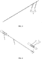
- the present application provides a lifting device as shown in FIG. 1 .
- the lifting device includes a tube-shaped conveyor portion 2, a handgrip 3, and the one-way lifting embedded thread 1 described in the preceding embodiment.
- the tube-shaped conveyor portion 2 includes a secured end and an open end. The secured end is secured to the handgrip 3.
- the open end is provided with an embedded thread outlet 21.
- the partially enlarged region illustrates the structure of the one-way lifting embedded thread 1 and the state when one-way lifting embedded thread 1 is threaded out of the embedded thread outlet 21.
- the lifting end of the pulling thread 11 of the one-way lifting embedded thread 1 is threaded through the inside of the tube-shaped conveyor portion 2 and then out of the embedded thread outlet 21.
- Terms “thread out of” and “thread through” herein refer to positional relationships and states during installation, and do not refer to installation actions or methods.
- the embedded thread outlet 21 is provided with a cam body position adjusting member 22.
- the cam body position adjusting member 22 is configured to readjust the cam body 12 to back predetermined positions when the tube-shaped conveyance portion 2 is withdrawn from the skin tissue.
- an optional cam body position adjusting member 22 is a clamping baffle disposed at the embedded thread outlet 21.
- the clamping baffle is made of a soft plastic material.
- the soft plastic material is any one or a combination of at least two of silicone rubber, polyurethane (PU), polypropylene (PP), high-density polyethylene (HDPE), and polytetrafluoroethylene (PTFE).
- a necking structure recessed inward in the radial direction of the tube-shaped conveyor portion 2 may be designed at the open end of the tube-shaped conveyor portion 2.
- the necking structure is configured to readjust the cam body 12 back to predetermined position when the tube-shaped conveyor portion 2 is withdrawn from the skin tissue.
- the present application provides a plastic surgery method using the preceding lifting device to perform lifting.
- the plastic surgery method includes the steps below.
- Threading is implemented before the surgery.
- the threading process includes: tightening the one-way lifting embedded thread 1; threading the lifting end of the pulling thread 11 into the handgrip 3 of the lifting device, through the inside of the tube-shaped conveyor portion 2, and then out of the embedded thread outlet 21 by using a threading tool; retaining the redundant part of the pulling thread 11; and then bending the redundant part of the pulling thread 11.
- the redundant part of the pulling thread 11 is used for facilitating the surgeon in pressing the skin tissue to securing the one-way lifting embedded thread 1 when withdrawing the needle in the surgery. Accordingly, the one-way lifting embedded thread 1 is prevented from being withdrawn along with the tube-shaped conveyor portion 2 while the needle is being withdrawn.
- Terms "thread into” and “thread out of” herein refer to installation actions or methods, and do not refer to installation states and positional relationships.
- the surgery process includes the steps below.
- step (I) the skin tissue is pricked with the lifting device.
- the cam on the one-way lifting embedded thread 1 the cross-sectional area increases gradually from the small end face to the large end face, which facilitates entering the tissue and mitigating an injury to the tissue.
- the skin tissue is pressed to secure the lifting end of the pulling thread 11 of the one-way lifting embedded thread 1 (that is, the redundant part of the pulling thread 11 retained in threading before the surgery) and the tube-shaped conveyor portion 2 is withdrawn slowly at the same time.
- step (II) at the same time of when the tube-shaped conveyor portion 2 is withdrawn, the skin tissue is pressed by the surgeon to secure the free end of the pulling thread 11 to become unmovable. In this case, the tube-shaped conveyor portion 2 is withdrawn while the one-way lifting embedded thread 1 still stays in the skin tissue.
- the cam body position adjusting member 22 of cam bodies 12 and/or the necking structure that is disposed at the embedded thread outlet 21 readjusts the cam bodies 12 to the positions of the stoppers and/or straightens and tightens the one-way lifting embedded thread 1 so that large end faces of the cam bodies 12 are fastened by the stoppers, guaranteeing no offset in the relative position of each cam body 12 entering the skin tissue. In this case, the skin tissue is forced evenly under the lifting action of the cam bodies 12.
- step (III) after the tube-shaped conveyor portion 2 is withdrawn, most of the one-way lifting embedded thread 1 stays in the skin tissue. However, the free end of the pulling thread 11 of the one-way lifting embedded thread 1 stays outside the skin tissue. The surgeon lifts the free end of the pulling thread 11 to adjust the lifting force to remove wrinkles.
- the one-way lifting embedded thread 1 stays in the skin tissue.
- the one-way lifting embedded thread 1 is made of a biodegradable material that is degradable inside the human tissue, thus causing no toxic or side effects on the human body.
- a plurality of one-way lifting embedded threads 1 are embedded in the same pricked hole by repeating step (I) and step (II). After embedding, free ends of pulling threads 11 of the one-way lifting embedded threads 1 are knotted in pairs or with each other so as to be secured at the pricked hole. This reduces the number of pricked holes, implements lifting on multiple parts, and avoids apparent surgical signs or irretrievable scars after the surgery.
- the one-way lifting embedded thread 1 includes a pulling thread 11 and four cam bodies 12 sleeved on the pulling thread 11. Each cam body 12 is equally spaced apart on the pulling thread 11. The distance between two adjacent cam bodies 12 is 15 mm. Thread knots are formed between adjacent cam bodies 12 by knotting the pulling thread 11 to define relative positions of the adjacent cam bodies 12.
- Two ends of the pulling thread 11 are a lifting end and a free end, respectively.
- the free end is provided with a hollow knot for securing the pulling thread.
- the hollow knot at the lifting end replaces part of the cam bodies 12 in the two-way lifting embedded thread that are configured to clamp the skin tissue, thus preventing the lifting embedded thread from completely slipping into the skin tissue, enhancing the lifting force, and shortening lifting duration.
- the cam body 12 Two sides of a cam body 12 are a large end face and a small end face, respectively.
- the large end face faces the free end of the pulling thread 11.
- the small end face faces the lifting end of the pulling thread 11.
- the cam body 12 is a tapered structure penetrated in the axial direction of the cam body 12.
- the wall thickness at the small end face is 0.9 mm.
- the wall thickness at the large end face is 0.2 mm. In the direction from the small end face to the large end face, the wall thickness of the cam body 12 reduces gradually. That is, the wall thickness of the cam body 12 reduces evenly from 0.9 mm to 0.2 mm.
- the cam bodies 12 and the pulling thread 11 are made of a degradable material that does not need to be taken out after the surgery but is degraded in the body.
- the surface of the cam bodies 12 and the surface of the pulling thread 11 are loaded with a non-steroid anti-inflammatory drug.
- the lifting device includes a tube-shaped conveyor portion 2, a handgrip 3, and the preceding one-way lifting embedded thread 1.
- the tube-shaped conveyor portion 2 includes a secured end and an open end. The secured end is secured to the handgrip 3. The open end is provided with an embedded thread outlet 21. The lifting end of the pulling thread 11 of the one-way lifting embedded thread 1 is threaded through the inside of the tube-shaped conveyor portion 2 and then out of the embedded thread outlet 21.
- a clamping baffle made of silicone rubber is disposed at the embedded thread outlet 21.
- the clamping baffle is configured to, when the tube-shaped conveyor portion 2 is withdrawn from the skin tissue, readjust the cam bodies 12 back to predetermined positions and straighten and tighten the one-way lifting embedded thread 1.
- the clamping baffle is secured inside the tube-shaped conveyor portion 2 in the radial direction of the tube-shaped conveyor portion 2.
- the clamping baffle disposed at the embedded thread outlet 21 applies friction to the cam bodies 12.
- the cam bodies 12 are readjusted to the positions of the thread knots so that large end faces of the cam bodies 12 are fastened by the stoppers, guaranteeing no offset in the relative position of each cam body 12 entering the skin tissue. In this case, the skin tissue is forced evenly under the lifting action of the cam bodies 12.
- friction applied to the cam bodies 12 helps straighten and tighten the one-way lifting embedded thread 1 so as to prevent the one-way lifting embedded thread 1 from winding inside the skin tissue, causing an uneven force in the process of lifting, and affecting the lifting effect.
- the one-way lifting embedded thread 1 includes a pulling thread 11 and fourteen cam bodies 12 sleeved on the pulling thread 11. Each cam body 12 is equally spaced apart on the pulling thread 11. The distance between two adjacent cam bodies 12 is 5.5 mm. The cam bodies are secured to the pulling thread 11 through an adhesive.
- Two ends of the pulling thread 11 are a lifting end and a free end, respectively.
- the free end is provided with a clamp for securing the pulling thread 11.
- the clamp structure may include a one-way barb structure disposed on the pulling thread 11 and a clamp head interacting with the barb structure to implement one-way locking. After the clamp head and the barb structure are locked, the entire clamp structure can only move forward but cannot move backward.
- the clamp structure replaces part of the cam bodies 12 in the two-way lifting embedded thread that are configured to clamp the skin tissue, thus preventing the lifting embedded thread from completely slipping into the skin tissue, enhancing the lifting force, and shortening lifting duration.
- Two sides of a cam body 12 are a large end face and a small end face.
- the large end face faces the free end of the pulling thread 11.
- the small end face faces the lifting end of the pulling thread 11.
- the cam body 12 is a tapered structure penetrated in the axial direction of the cam body 12.
- the wall thickness at the small end face is 0.1 mm.
- the wall thickness at the large end face is 0.05 mm. In the direction from the small end face to the large end face, the wall thickness of the cam body 12 reduces gradually. That is, the wall thickness of the cam body 12 reduces evenly from 0.1 mm to 0.05 mm.
- the cam bodies 12 and the pulling thread 11 are made of a degradable material that does not need to be taken out after the surgery but is degraded in the body.
- the surface of the cam bodies 12 and the surface of the pulling thread 11 are loaded with a steroid anti-inflammatory drug.
- the lifting device includes a tube-shaped conveyor portion 2, a handgrip 3, and the preceding one-way lifting embedded thread 1.
- the tube-shaped conveyor portion 2 includes a secured end and an open end. The secured end is secured to the handgrip 3. The open end is provided with an embedded thread outlet 21. The lifting end of the pulling thread 11 of the one-way lifting embedded thread 1 is threaded through the inside of the tube-shaped conveyor portion 2 and then out of the embedded thread outlet 21.
- a necking structure recessed inward in the radial direction of the tube-shaped conveyor portion 2 is designed at the open end of the tube-shaped conveyor portion 2.
- the necking structure is configured to straighten and tighten the one-way lifting embedded thread 1 when the tube-shaped conveyor portion 2 is withdrawn from the skin tissue so as to prevent the one-way lifting embedded thread 1 from winding inside the skin tissue.
- the clamping baffle is secured inside the tube-shaped conveyor portion 2 in the axial direction of the tube-shaped conveyor portion 2.
- the necking structure applies friction to the cam bodies 12 and thus straightens and tightens the one-way lifting embedded thread 1 so as to prevent the one-way lifting embedded thread 1 from winding inside the skin tissue, causing an uneven force in the process of lifting, and affecting the lifting effect.
- the one-way lifting embedded thread 1 includes a pulling thread 11 and ten cam bodies 12 sleeved on the pulling thread 11. Each cam body 12 is equally spaced apart on the pulling thread 11. The distance between two adjacent cam bodies 12 is 5.5 mm. The cam bodies are secured to the pulling thread 11 through heat sealing.
- Two ends of the pulling thread 11 are a lifting end and a free end, respectively.
- the lifting end is provided with a hollow knot for securing the pulling thread 11.
- the hollow knot replaces part of the cam bodies 12 in the two-way lifting embedded thread that are configured to clamp the skin tissue, thus preventing the lifting embedded thread from completely slipping into the skin tissue, enhancing the lifting force, and shortening lifting duration.
- Two sides of a cam body 12 are a large end face and a small end face.
- the large end face faces the free end of the pulling thread 11.
- the small end face faces the lifting end of the pulling thread 11.
- the cam body 12 is a tapered structure penetrated in the axial direction of the cam body 12.
- the wall thickness at the small end face is 0.3 mm.
- the wall thickness at the large end face is 0.09 mm. In the direction from the small end face to the large end face, the wall thickness of the cam body 12 reduces gradually. That is, the wall thickness of the cam body 12 reduces evenly from 0.3 mm to 0.09 mm.
- the cam bodies 12 and the pulling thread 11 are made of a degradable material that does not need to be taken out after the surgery but is degraded in the body.
- the surface of the cam bodies 12 and the surface of the pulling thread 11 are loaded with an opiate drug.
- the lifting device includes a tube-shaped conveyor portion 2, a handgrip 3, and the preceding one-way lifting embedded thread 1.
- the tube-shaped conveyor portion 2 includes a secured end and an open end. The secured end is secured to the handgrip 3. The open end is provided with an embedded thread outlet 21. The lifting end of the pulling thread 11 of the one-way lifting embedded thread 1 is threaded through the inside of the tube-shaped conveyor portion 2 and then out of the embedded thread outlet 21.
- a clamping baffle made of HDPE is disposed at the embedded thread outlet 21.
- a necking structure recessed inward in the radial direction of the tube-shaped conveyor portion 2 is designed at the open end of the tube-shaped conveyor portion 2.
- the clamping baffle and the necking structure are configured to straighten and tighten the one-way lifting embedded thread when the tube-shaped conveyor portion 2 is withdrawn from the skin tissue so as to prevent the one-way lifting embedded thread 1 from winding inside the skin tissue.
- the clamping baffle is secured inside the tube-shaped conveyor portion 2 in the axial direction of tube-shaped conveyor portion 2.
- the clamping baffle disposed at the embedded thread outlet 21 and the necking structure designed at the open end apply friction to the cam bodies 12 and thus straightens and tightens the one-way lifting embedded thread 1 so as to prevent the one-way lifting embedded thread 1 from winding inside the skin tissue, causing an uneven force in the process of lifting, and affecting the lifting effect.
Landscapes
- Health & Medical Sciences (AREA)
- Life Sciences & Earth Sciences (AREA)
- Surgery (AREA)
- General Health & Medical Sciences (AREA)
- Public Health (AREA)
- Biomedical Technology (AREA)
- Heart & Thoracic Surgery (AREA)
- Engineering & Computer Science (AREA)
- Veterinary Medicine (AREA)
- Animal Behavior & Ethology (AREA)
- Molecular Biology (AREA)
- Nuclear Medicine, Radiotherapy & Molecular Imaging (AREA)
- Medical Informatics (AREA)
- Oral & Maxillofacial Surgery (AREA)
- Transplantation (AREA)
- Cardiology (AREA)
- Vascular Medicine (AREA)
- Pathology (AREA)
- Rheumatology (AREA)
- Surgical Instruments (AREA)
- Prostheses (AREA)
- Materials For Medical Uses (AREA)
Applications Claiming Priority (2)
| Application Number | Priority Date | Filing Date | Title |
|---|---|---|---|
| CN201910531045.4A CN110123485B (zh) | 2019-06-19 | 2019-06-19 | 一种单向提拉埋植线、提拉装置及使用其的整形方法 |
| PCT/CN2020/076357 WO2020253256A1 (zh) | 2019-06-19 | 2020-02-24 | 一种单向提拉埋植线、提拉装置及使用其的整形方法 |
Publications (3)
| Publication Number | Publication Date |
|---|---|
| EP3915516A1 true EP3915516A1 (de) | 2021-12-01 |
| EP3915516A4 EP3915516A4 (de) | 2022-03-23 |
| EP3915516B1 EP3915516B1 (de) | 2026-02-11 |
Family
ID=67578109
Family Applications (1)
| Application Number | Title | Priority Date | Filing Date |
|---|---|---|---|
| EP20826661.9A Active EP3915516B1 (de) | 2019-06-19 | 2020-02-24 | Lifting vorrichtung |
Country Status (6)
| Country | Link |
|---|---|
| US (1) | US20220000471A1 (de) |
| EP (1) | EP3915516B1 (de) |
| JP (1) | JP2022524195A (de) |
| KR (1) | KR102665937B1 (de) |
| CN (1) | CN110123485B (de) |
| WO (1) | WO2020253256A1 (de) |
Families Citing this family (7)
| Publication number | Priority date | Publication date | Assignee | Title |
|---|---|---|---|---|
| CN110123485B (zh) * | 2019-06-19 | 2024-05-28 | 童妍(上海)医疗器械有限公司 | 一种单向提拉埋植线、提拉装置及使用其的整形方法 |
| CN112674906B (zh) * | 2020-12-24 | 2024-07-09 | 童妍(上海)医疗器械有限公司 | 一种提拉线及其制备方法 |
| CN112842431B (zh) * | 2021-03-18 | 2024-12-31 | 童妍(上海)医疗器械有限公司 | 一种提拉线 |
| CN112890894B (zh) * | 2021-03-18 | 2024-12-31 | 童妍(上海)医疗器械有限公司 | 一种提拉线 |
| US11413038B1 (en) * | 2021-12-18 | 2022-08-16 | Xiaoqin Ling | Facial invasive tissue treatment method |
| CN115105647B (zh) * | 2022-06-17 | 2023-06-30 | 北京诺康达医药科技股份有限公司 | 一种美容提拉线及其制备方法 |
| CN118526321B (zh) * | 2024-05-29 | 2025-02-11 | 上海璞聚生物科技有限公司 | 一种面部可吸收软组织提拉装置及其植入辅助装置 |
Family Cites Families (27)
| Publication number | Priority date | Publication date | Assignee | Title |
|---|---|---|---|---|
| US5342376A (en) * | 1993-05-03 | 1994-08-30 | Dermagraphics, Inc. | Inserting device for a barbed tissue connector |
| US7582105B2 (en) * | 2004-06-30 | 2009-09-01 | Silhouette Lift Societad Limitada | Suture for wound closure, tissue approximation, tissue support, suspension and/or fixation |
| EP2214568B1 (de) * | 2007-11-15 | 2013-08-14 | Marian Devonec | Vorrichtung zur modellierung oder straffung von normalem oder ausgedehntem gewebe bei menschen |
| US8876865B2 (en) * | 2008-04-15 | 2014-11-04 | Ethicon, Inc. | Self-retaining sutures with bi-directional retainers or uni-directional retainers |
| US8226684B2 (en) * | 2008-12-22 | 2012-07-24 | Ethicon, Inc. | Surgical sutures having collapsible tissue anchoring protrusions and methods therefor |
| CN201404310Y (zh) * | 2009-05-22 | 2010-02-17 | 浙江普洛医药科技有限公司 | 整形手术用的空心锥悬提线 |
| CN103889340B (zh) * | 2011-03-23 | 2018-09-28 | 伊西康有限责任公司 | 自固位式可变套环缝合线 |
| KR20120117609A (ko) * | 2011-04-14 | 2012-10-24 | 김병건 | 피부삽입용 기능성 시술 실, 및 이를 포함하는 시술장치 |
| US9694106B2 (en) * | 2011-07-11 | 2017-07-04 | Mimedx Group, Inc. | Synthetic collagen threads for cosmetic uses including skin wrinkle treatments and associated methods |
| US10010317B2 (en) * | 2012-12-05 | 2018-07-03 | Young Jae Kim | Method of improving elasticity of tissue of living body |
| WO2015006596A1 (en) * | 2013-07-10 | 2015-01-15 | Tepha, Inc, | Soft suture anchors |
| GB2537033B (en) * | 2015-02-27 | 2017-02-08 | Sinclair Pharmaceuticals Ltd | Device |
| US10188379B2 (en) * | 2015-09-03 | 2019-01-29 | Ethicon Llc | End effector for wound closure device |
| US20170281160A1 (en) * | 2016-03-31 | 2017-10-05 | Beauty-Com Biotechnology Co., Ltd | Surgical suture |
| EP3225175A1 (de) * | 2016-04-01 | 2017-10-04 | Beauty-Com Biotechnology Co., Ltd | Chirurgische naht |
| CA3029530C (en) * | 2016-07-08 | 2022-05-31 | Dongbang Medical Co., Ltd. | Suture for lifting and manufacturing method therefor |
| KR101790938B1 (ko) * | 2016-09-05 | 2017-10-27 | 주식회사 용창 | 성형용 의료용실 삽입기 |
| GB2540293B (en) * | 2016-10-02 | 2018-02-14 | Hasan Ali Falah | Beads enriched silhouette soft (TM) face lift suture |
| CN207886513U (zh) * | 2017-05-05 | 2018-09-21 | 郑卓 | 一种胶原蛋白双线植入装置 |
| CN207855729U (zh) * | 2017-07-03 | 2018-09-14 | 崔娟 | 一种美容用提线针 |
| CN208228962U (zh) * | 2017-07-28 | 2018-12-14 | 北京五维医疗美容门诊部有限公司 | 一种圆环式提升线悬吊结构 |
| CN207804289U (zh) * | 2017-10-20 | 2018-09-04 | 北京凯诺瑞和医疗器械有限公司 | 一种新型美容提拉线 |
| KR102038477B1 (ko) * | 2017-10-20 | 2019-10-30 | 21세기메디칼 주식회사 | 실 삽입기 |
| KR20190059673A (ko) * | 2017-11-23 | 2019-05-31 | 주식회사 지엠디 | 피부 리프팅용 수술 도구 |
| CN109864835B (zh) * | 2019-04-15 | 2024-06-11 | 童妍(上海)医疗器械有限公司 | 一种缝合线、缝合装置及其应用 |
| CN110123485B (zh) * | 2019-06-19 | 2024-05-28 | 童妍(上海)医疗器械有限公司 | 一种单向提拉埋植线、提拉装置及使用其的整形方法 |
| CN210521145U (zh) * | 2019-06-19 | 2020-05-15 | 易浦润(上海)生物技术有限公司 | 一种单向提拉埋植线和包括其的提拉装置 |
-
2019
- 2019-06-19 CN CN201910531045.4A patent/CN110123485B/zh active Active
-
2020
- 2020-02-24 EP EP20826661.9A patent/EP3915516B1/de active Active
- 2020-02-24 JP JP2021553851A patent/JP2022524195A/ja active Pending
- 2020-02-24 WO PCT/CN2020/076357 patent/WO2020253256A1/zh not_active Ceased
- 2020-02-24 KR KR1020217037955A patent/KR102665937B1/ko active Active
-
2021
- 2021-09-09 US US17/470,822 patent/US20220000471A1/en not_active Abandoned
Also Published As
| Publication number | Publication date |
|---|---|
| KR102665937B1 (ko) | 2024-05-14 |
| WO2020253256A1 (zh) | 2020-12-24 |
| JP2022524195A (ja) | 2022-04-28 |
| CN110123485B (zh) | 2024-05-28 |
| EP3915516B1 (de) | 2026-02-11 |
| CN110123485A (zh) | 2019-08-16 |
| US20220000471A1 (en) | 2022-01-06 |
| KR20210154846A (ko) | 2021-12-21 |
| EP3915516A4 (de) | 2022-03-23 |
Similar Documents
| Publication | Publication Date | Title |
|---|---|---|
| EP3915516A1 (de) | Eindirektionaler catgut-faden für lifting, lifting-vorrichtung und verfahren zur plastischen chirurgie damit | |
| US10595985B2 (en) | Minimally invasive breast lift method with a superior tissue support and an inferior anchor | |
| EP3915491A1 (de) | Nähfaden, nähvorrichtung und anwendungen davon | |
| US20170348090A1 (en) | Minimally invasive tissue support | |
| US20120150194A1 (en) | Thread having coated anchoring structures for anchoring in biological tissues and process for production thereof | |
| EP2427126B1 (de) | Beschichteter faden mit verankerungsmerkmalen zur verankerung in biologischen geweben | |
| TWI601548B (zh) | 以外科手術線預充之用於整形外科的注射針 | |
| EP2427127B1 (de) | Elastomerer faden mit verankerungsmerkmalen zur verankerung in biologischen geweben | |
| KR20170038364A (ko) | 봉합사 삽입을 위한 피부 시술 도구 및 이를 포함하는 키트 | |
| US12274611B1 (en) | Systems and methods for superficial facial fat pad repositioning | |
| WO2020211527A1 (zh) | 一种缝合线、缝合装置及其应用 | |
| CN210521145U (zh) | 一种单向提拉埋植线和包括其的提拉装置 | |
| WO2015137882A1 (en) | A system for cosmetic enhancement | |
| US20090030453A1 (en) | Surgical Device | |
| RU2815221C1 (ru) | Нить для лифтинга тяжёлых тканей | |
| CN219271006U (zh) | 锚钉 | |
| WO2025071440A1 (ru) | Нить для лифтинга тяжёлых тканей |
Legal Events
| Date | Code | Title | Description |
|---|---|---|---|
| STAA | Information on the status of an ep patent application or granted ep patent |
Free format text: STATUS: THE INTERNATIONAL PUBLICATION HAS BEEN MADE |
|
| PUAI | Public reference made under article 153(3) epc to a published international application that has entered the european phase |
Free format text: ORIGINAL CODE: 0009012 |
|
| STAA | Information on the status of an ep patent application or granted ep patent |
Free format text: STATUS: REQUEST FOR EXAMINATION WAS MADE |
|
| 17P | Request for examination filed |
Effective date: 20210827 |
|
| AK | Designated contracting states |
Kind code of ref document: A1 Designated state(s): AL AT BE BG CH CY CZ DE DK EE ES FI FR GB GR HR HU IE IS IT LI LT LU LV MC MK MT NL NO PL PT RO RS SE SI SK SM TR |
|
| REG | Reference to a national code |
Ref country code: DE Free format text: PREVIOUS MAIN CLASS: A61F0002020000 Ref country code: DE Ref legal event code: R079 Ref document number: 602020066771 Country of ref document: DE Free format text: PREVIOUS MAIN CLASS: A61F0002020000 Ipc: A61B0017000000 |
|
| A4 | Supplementary search report drawn up and despatched |
Effective date: 20220221 |
|
| RIC1 | Information provided on ipc code assigned before grant |
Ipc: A61B 17/06 20060101ALI20220215BHEP Ipc: A61B 17/00 20060101AFI20220215BHEP |
|
| DAV | Request for validation of the european patent (deleted) | ||
| DAX | Request for extension of the european patent (deleted) | ||
| STAA | Information on the status of an ep patent application or granted ep patent |
Free format text: STATUS: EXAMINATION IS IN PROGRESS |
|
| 17Q | First examination report despatched |
Effective date: 20230601 |
|
| GRAP | Despatch of communication of intention to grant a patent |
Free format text: ORIGINAL CODE: EPIDOSNIGR1 |
|
| STAA | Information on the status of an ep patent application or granted ep patent |
Free format text: STATUS: GRANT OF PATENT IS INTENDED |
|
| INTG | Intention to grant announced |
Effective date: 20250917 |
|
| GRAS | Grant fee paid |
Free format text: ORIGINAL CODE: EPIDOSNIGR3 |
|
| GRAA | (expected) grant |
Free format text: ORIGINAL CODE: 0009210 |
|
| STAA | Information on the status of an ep patent application or granted ep patent |
Free format text: STATUS: THE PATENT HAS BEEN GRANTED |
|
| AK | Designated contracting states |
Kind code of ref document: B1 Designated state(s): AL AT BE BG CH CY CZ DE DK EE ES FI FR GB GR HR HU IE IS IT LI LT LU LV MC MK MT NL NO PL PT RO RS SE SI SK SM TR |
|
| REG | Reference to a national code |
Ref country code: CH Ref legal event code: F10 Free format text: ST27 STATUS EVENT CODE: U-0-0-F10-F00 (AS PROVIDED BY THE NATIONAL OFFICE) Effective date: 20260211 Ref country code: GB Ref legal event code: FG4D |
|
| REG | Reference to a national code |
Ref country code: DE Ref legal event code: R096 Ref document number: 602020066771 Country of ref document: DE |
|
| REG | Reference to a national code |
Ref country code: IE Ref legal event code: FG4D |
|
| PGFP | Annual fee paid to national office [announced via postgrant information from national office to epo] |
Ref country code: GB Payment date: 20260214 Year of fee payment: 7 |
|
| PGFP | Annual fee paid to national office [announced via postgrant information from national office to epo] |
Ref country code: FR Payment date: 20260209 Year of fee payment: 7 |