EP3916200A1 - Systèmes et procédés de refroidissement d'une paroi d'extrémité dans une machine rotative - Google Patents
Systèmes et procédés de refroidissement d'une paroi d'extrémité dans une machine rotative Download PDFInfo
- Publication number
- EP3916200A1 EP3916200A1 EP21170808.6A EP21170808A EP3916200A1 EP 3916200 A1 EP3916200 A1 EP 3916200A1 EP 21170808 A EP21170808 A EP 21170808A EP 3916200 A1 EP3916200 A1 EP 3916200A1
- Authority
- EP
- European Patent Office
- Prior art keywords
- pass
- cooling fluid
- inlet portion
- flow
- core
- Prior art date
- Legal status (The legal status is an assumption and is not a legal conclusion. Google has not performed a legal analysis and makes no representation as to the accuracy of the status listed.)
- Pending
Links
Images


Classifications
-
- F—MECHANICAL ENGINEERING; LIGHTING; HEATING; WEAPONS; BLASTING
- F01—MACHINES OR ENGINES IN GENERAL; ENGINE PLANTS IN GENERAL; STEAM ENGINES
- F01D—NON-POSITIVE DISPLACEMENT MACHINES OR ENGINES, e.g. STEAM TURBINES
- F01D5/00—Blades; Blade-carrying members; Heating, heat-insulating, cooling or antivibration means on the blades or the members
- F01D5/12—Blades
- F01D5/14—Form or construction
- F01D5/18—Hollow blades, i.e. blades with cooling or heating channels or cavities; Heating, heat-insulating or cooling means on blades
- F01D5/187—Convection cooling
-
- F—MECHANICAL ENGINEERING; LIGHTING; HEATING; WEAPONS; BLASTING
- F02—COMBUSTION ENGINES; HOT-GAS OR COMBUSTION-PRODUCT ENGINE PLANTS
- F02C—GAS-TURBINE PLANTS; AIR INTAKES FOR JET-PROPULSION PLANTS; CONTROLLING FUEL SUPPLY IN AIR-BREATHING JET-PROPULSION PLANTS
- F02C7/00—Features, components parts, details or accessories, not provided for in, or of interest apart form groups F02C1/00 - F02C6/00; Air intakes for jet-propulsion plants
- F02C7/12—Cooling of plants
-
- F—MECHANICAL ENGINEERING; LIGHTING; HEATING; WEAPONS; BLASTING
- F01—MACHINES OR ENGINES IN GENERAL; ENGINE PLANTS IN GENERAL; STEAM ENGINES
- F01D—NON-POSITIVE DISPLACEMENT MACHINES OR ENGINES, e.g. STEAM TURBINES
- F01D25/00—Component parts, details, or accessories, not provided for in, or of interest apart from, other groups
- F01D25/08—Cooling; Heating; Heat-insulation
- F01D25/14—Casings modified therefor
-
- F—MECHANICAL ENGINEERING; LIGHTING; HEATING; WEAPONS; BLASTING
- F01—MACHINES OR ENGINES IN GENERAL; ENGINE PLANTS IN GENERAL; STEAM ENGINES
- F01D—NON-POSITIVE DISPLACEMENT MACHINES OR ENGINES, e.g. STEAM TURBINES
- F01D25/00—Component parts, details, or accessories, not provided for in, or of interest apart from, other groups
- F01D25/08—Cooling; Heating; Heat-insulation
- F01D25/12—Cooling
- F01D25/125—Cooling of bearings
-
- F—MECHANICAL ENGINEERING; LIGHTING; HEATING; WEAPONS; BLASTING
- F01—MACHINES OR ENGINES IN GENERAL; ENGINE PLANTS IN GENERAL; STEAM ENGINES
- F01D—NON-POSITIVE DISPLACEMENT MACHINES OR ENGINES, e.g. STEAM TURBINES
- F01D5/00—Blades; Blade-carrying members; Heating, heat-insulating, cooling or antivibration means on the blades or the members
- F01D5/12—Blades
- F01D5/22—Blade-to-blade connections, e.g. for damping vibrations
- F01D5/225—Blade-to-blade connections, e.g. for damping vibrations by shrouding
-
- F—MECHANICAL ENGINEERING; LIGHTING; HEATING; WEAPONS; BLASTING
- F01—MACHINES OR ENGINES IN GENERAL; ENGINE PLANTS IN GENERAL; STEAM ENGINES
- F01D—NON-POSITIVE DISPLACEMENT MACHINES OR ENGINES, e.g. STEAM TURBINES
- F01D9/00—Stators
- F01D9/02—Nozzles; Nozzle boxes; Stator blades; Guide conduits, e.g. individual nozzles
-
- F—MECHANICAL ENGINEERING; LIGHTING; HEATING; WEAPONS; BLASTING
- F01—MACHINES OR ENGINES IN GENERAL; ENGINE PLANTS IN GENERAL; STEAM ENGINES
- F01D—NON-POSITIVE DISPLACEMENT MACHINES OR ENGINES, e.g. STEAM TURBINES
- F01D9/00—Stators
- F01D9/02—Nozzles; Nozzle boxes; Stator blades; Guide conduits, e.g. individual nozzles
- F01D9/04—Nozzles; Nozzle boxes; Stator blades; Guide conduits, e.g. individual nozzles forming ring or sector
- F01D9/041—Nozzles; Nozzle boxes; Stator blades; Guide conduits, e.g. individual nozzles forming ring or sector using blades
-
- F—MECHANICAL ENGINEERING; LIGHTING; HEATING; WEAPONS; BLASTING
- F01—MACHINES OR ENGINES IN GENERAL; ENGINE PLANTS IN GENERAL; STEAM ENGINES
- F01D—NON-POSITIVE DISPLACEMENT MACHINES OR ENGINES, e.g. STEAM TURBINES
- F01D9/00—Stators
- F01D9/06—Fluid supply conduits to nozzles or the like
- F01D9/065—Fluid supply or removal conduits traversing the working fluid flow, e.g. for lubrication-, cooling-, or sealing fluids
-
- F—MECHANICAL ENGINEERING; LIGHTING; HEATING; WEAPONS; BLASTING
- F05—INDEXING SCHEMES RELATING TO ENGINES OR PUMPS IN VARIOUS SUBCLASSES OF CLASSES F01-F04
- F05D—INDEXING SCHEME FOR ASPECTS RELATING TO NON-POSITIVE-DISPLACEMENT MACHINES OR ENGINES, GAS-TURBINES OR JET-PROPULSION PLANTS
- F05D2220/00—Application
- F05D2220/30—Application in turbines
- F05D2220/32—Application in turbines in gas turbines
-
- F—MECHANICAL ENGINEERING; LIGHTING; HEATING; WEAPONS; BLASTING
- F05—INDEXING SCHEMES RELATING TO ENGINES OR PUMPS IN VARIOUS SUBCLASSES OF CLASSES F01-F04
- F05D—INDEXING SCHEME FOR ASPECTS RELATING TO NON-POSITIVE-DISPLACEMENT MACHINES OR ENGINES, GAS-TURBINES OR JET-PROPULSION PLANTS
- F05D2240/00—Components
- F05D2240/80—Platforms for stationary or moving blades
- F05D2240/81—Cooled platforms
-
- F—MECHANICAL ENGINEERING; LIGHTING; HEATING; WEAPONS; BLASTING
- F05—INDEXING SCHEMES RELATING TO ENGINES OR PUMPS IN VARIOUS SUBCLASSES OF CLASSES F01-F04
- F05D—INDEXING SCHEME FOR ASPECTS RELATING TO NON-POSITIVE-DISPLACEMENT MACHINES OR ENGINES, GAS-TURBINES OR JET-PROPULSION PLANTS
- F05D2260/00—Function
- F05D2260/20—Heat transfer, e.g. cooling
- F05D2260/201—Heat transfer, e.g. cooling by impingement of a fluid
-
- F—MECHANICAL ENGINEERING; LIGHTING; HEATING; WEAPONS; BLASTING
- F05—INDEXING SCHEMES RELATING TO ENGINES OR PUMPS IN VARIOUS SUBCLASSES OF CLASSES F01-F04
- F05D—INDEXING SCHEME FOR ASPECTS RELATING TO NON-POSITIVE-DISPLACEMENT MACHINES OR ENGINES, GAS-TURBINES OR JET-PROPULSION PLANTS
- F05D2260/00—Function
- F05D2260/20—Heat transfer, e.g. cooling
- F05D2260/202—Heat transfer, e.g. cooling by film cooling
-
- F—MECHANICAL ENGINEERING; LIGHTING; HEATING; WEAPONS; BLASTING
- F05—INDEXING SCHEMES RELATING TO ENGINES OR PUMPS IN VARIOUS SUBCLASSES OF CLASSES F01-F04
- F05D—INDEXING SCHEME FOR ASPECTS RELATING TO NON-POSITIVE-DISPLACEMENT MACHINES OR ENGINES, GAS-TURBINES OR JET-PROPULSION PLANTS
- F05D2260/00—Function
- F05D2260/20—Heat transfer, e.g. cooling
- F05D2260/221—Improvement of heat transfer
- F05D2260/2212—Improvement of heat transfer by creating turbulence
-
- Y—GENERAL TAGGING OF NEW TECHNOLOGICAL DEVELOPMENTS; GENERAL TAGGING OF CROSS-SECTIONAL TECHNOLOGIES SPANNING OVER SEVERAL SECTIONS OF THE IPC; TECHNICAL SUBJECTS COVERED BY FORMER USPC CROSS-REFERENCE ART COLLECTIONS [XRACs] AND DIGESTS
- Y02—TECHNOLOGIES OR APPLICATIONS FOR MITIGATION OR ADAPTATION AGAINST CLIMATE CHANGE
- Y02T—CLIMATE CHANGE MITIGATION TECHNOLOGIES RELATED TO TRANSPORTATION
- Y02T50/00—Aeronautics or air transport
- Y02T50/60—Efficient propulsion technologies, e.g. for aircraft
Definitions
- the field of the disclosure relates generally to cooling systems and, more specifically, to impingement cooling of rotary machine components.
- energy extracted from a gas stream in a turbine is used to power a mechanical load.
- various hot gas path components may be subjected to a high-temperature gas stream. Over time, continued exposure to high temperatures may induce wear in the hot gas path components.
- air is pressurized in a compressor and mixed with fuel in a combustor to generate high-temperature gases.
- higher temperature gases increase performance, efficiency, and power output of the rotary machine.
- at least some known hot gas path components are cooled. However, higher temperature gases can also increase thermal stresses and/or thermal degradation of the rotary machine components.
- Some known hot gas path components are formed with an endwall that includes an internal cooling system, wherein a cooling fluid, such as bleed air extracted from a compressor or steam, is forced through cores defined within the endwall.
- a cooling fluid such as bleed air extracted from a compressor or steam
- At least some known cores are formed with an inlet opening that channels the cooling fluid into the core and directs the cooling fluid to impinge on internal surfaces of the core, thus increasing cooling of the endwall.
- at least some known cores include a pin bank that channels the cooling fluid directly to at least one exit opening from the inlet opening rather than channeling the cooling fluid in a circuit through the endwall.
- the cores are not as efficiently cooled as cores that include serpentine or circuitous passages.
- at least some known cores have serpentine or circuitous passages that channel the cooling fluid through the endwall from a single inlet.
- modulating the pressure drop within the passages can be difficult in known cores.
- a core for use in cooling a component used in a rotary machine includes a passage including a first inlet portion, a second inlet portion, a divider, at least one first pass, at least one second pass, and at least one turn.
- the divider separates the first inlet portion from the second inlet portion such that the first inlet portion, the second inlet portion, and the divider define a split pass inlet.
- the at least one first pass channels a flow of cooling fluid in a first direction from the split pass inlet.
- the at least one second pass channels the flow of cooling fluid in a second direction opposite the first direction.
- the at least one turn changes a direction of flow of the cooling fluid from the first direction to the second direction.
- the at least one first pass, the at least one second pass, and the at least one turn are arranged such that the passage defines a serpentine passage.
- a gas turbine system in another aspect, includes a turbine section including an inner endwall, an outer endwall, a plurality of airfoils, and a core.
- the turbine section is coupled in flow communication with a combustion system.
- the inner endwall circumscribes the longitudinal axis of the gas turbine system.
- the outer endwall circumscribes a longitudinal axis of the gas turbine system and the inner endwall.
- the plurality of airfoils each extend between the outer endwall and the inner endwall.
- the core is positioned within at least one of the outer endwall and the inner endwall for cooling at least one of the outer endwall and the inner endwall.
- the core includes a passage including a first inlet portion, a second inlet portion, a divider, at least one first pass, at least one second pass, and at least one turn.
- the divider separates the first inlet portion from the second inlet portion such that the first inlet portion, the second inlet portion, and the divider define a split pass inlet.
- the at least one first pass channels a flow of cooling fluid in a first direction from the split pass inlet.
- the at least one second pass channels the flow of cooling fluid in a second direction opposite the first direction.
- the at least one turn changes a direction of flow of the cooling fluid from the first direction to the second direction.
- the at least one first pass, the at least one second pass, and the at least one turn are arranged such that the passage defines a serpentine passage.
- a method of cooling a component of a rotary machine includes inserting a core into a plenum within the component.
- the core includes a passage including an inlet portion, at least one first pass, at least one second pass, at least one turn.
- the inlet portion includes a first inlet portion, a second inlet portion, and a divider.
- the divider separates the first inlet portion from the second inlet portion such that the inlet portion is a split pass inlet.
- the method also includes channeling a flow of cooling fluid into the first inlet portion and the second inlet portion.
- the method further includes channeling the flow of cooling fluid from the first inlet portion and the second inlet portion into the at least one first pass.
- the flow of cooling fluid from the first inlet portion merges with the flow of cooling fluid from the second inlet portion, and the at least one first pass channels the flow of cooling fluid in a first direction.
- the method also includes channeling the flow of cooling fluid from the at least one first pass into the at least one turn.
- the at least one turn changes a direction of flow of the cooling fluid from the first direction to a second direction opposite the first direction.
- the method further includes channeling the flow of cooling fluid from the at least one turn into the at least one second pass.
- the at least one first pass, the at least one second pass, and the at least one turn are arranged such that the passage defines a serpentine passage.
- approximating language such as “generally,” “substantially,” and “about,” as used herein indicates that the term so modified may apply to only an approximate degree, as would be recognized by one of ordinary skill in the art, rather than to an absolute or perfect degree. Accordingly, a value modified by a term or terms such as “about,” “approximately,” and “substantially” is not to be limited to the precise value specified. In at least some instances, the approximating language may correspond to the precision of an instrument for measuring the value.
- range limitations may be identified. Such ranges may be combined and/or interchanged and include all the sub-ranges contained therein unless context or language indicates otherwise.
- first ⁇ ⁇ ⁇ ⁇ ⁇ ⁇ ⁇ ⁇ ⁇ ⁇ ⁇ ⁇ ⁇ ⁇ ⁇ ⁇ ⁇ ⁇ ⁇ ⁇ ⁇ ⁇ ⁇ ⁇ ⁇ ⁇ ⁇ ⁇ ⁇ ⁇ ⁇ ⁇ ⁇ ⁇ ⁇ ⁇ ⁇ ⁇ ⁇ ⁇ ⁇ ⁇ ⁇ ⁇ ⁇ ⁇ ⁇ ⁇ ⁇ ⁇ ⁇ ⁇ ⁇ ⁇ ⁇ ⁇ ⁇ ⁇ ⁇ ⁇ ⁇ ⁇ ⁇ ⁇ ⁇ ⁇ ⁇ ⁇ ⁇ ⁇ ⁇ ⁇ ⁇ ⁇ ⁇ ⁇ ⁇ ⁇ ⁇ ⁇ ⁇ ⁇ ⁇ ⁇ ⁇ ⁇ ⁇ ⁇ ⁇ ⁇ ⁇ ⁇ ⁇ ⁇ ⁇ ⁇ ⁇ ⁇ ⁇ ⁇ ⁇ ⁇ ⁇ ⁇ ⁇ ⁇ ⁇ ⁇ ⁇ ⁇ ⁇ ⁇ ⁇ ⁇ ⁇ ⁇ ⁇ ⁇ ⁇ ⁇ ⁇ ⁇ ⁇ ⁇ ⁇ ⁇
- the terms “axial” and “axially” refer to directions and orientations extending substantially parallel to a longitudinal axis of a rotary machine.
- the terms “radial” and “radially” refer to directions and orientations extending substantially perpendicular to the longitudinal axis of the rotary machine.
- the terms “circumferential” and “circumferentially” refer to directions and orientations extending arcuately about the longitudinal axis of the rotary machine.
- upstream refers to a forward or inlet end of a rotary machine
- downstream refers to an aft or exhaust end of the rotary machine.
- a rotary component includes an outer endwall formed in a nozzle of a turbine section within the rotary machine.
- the outer endwall includes a core for use in cooling the outer endwall.
- the core includes a serpentine passage including an inlet portion, a first pass, a second pass, and a turn.
- the inlet portion includes a divider, a first inlet portion, and a second inlet portion. The divider separates the first inlet portion from the second inlet portion, such that a split pass inlet is defined.
- the first pass, the second pass, and the turn include a plurality of outlets that channel cooling fluid from the core into the hot gas path to form a cooling film on the outer endwall.
- a plurality of core ties channels cooling fluid from an upstream portion of the core to a downstream portion of the core to enable the downstream portions to be replenished with lower temperature cooling fluid.
- cooling fluid is channeled through the first pass, the second pass, and the turn to facilitate cooling the outer endwall from within the core.
- the serpentine configuration of the first pass, the second pass, and the turn enables the cooling fluid to cool a larger area of the outer endwall, thus increasing the overall heat transfer between the cooling fluid and the outer endwall.
- the serpentine configuration enables the cooling fluid to circulate with a lower pressure that is substantially equal to the pressure of combustion gases at a throat of the nozzle.
- a width of each of the first pass, the second pass, and the turn is selected to facilitate modification of, or tune, the pressure drop of the cooling fluid through the first pass, the second pass, and the turn and to increase the overall heat transfer between the cooling fluid and the outer endwall.
- outlets channel cooling fluid into the hot gas path to facilitate forming a cooling film across the stator endwall.
- core ties replenish downstream portions of the core with cooling fluid, as well as provide inspection access, rigidity during core formation, and leachability for ceramic core removal after the casing process.
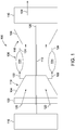
- FIG. 1 is a schematic view of an exemplary rotary machine 100, i.e., a turbomachine, and more specifically a turbine engine.
- rotary machine 100 is a gas turbine engine.
- rotary machine may be any other turbine engine and/or rotary machine, including, without limitation, a steam turbine engine, a gas turbofan aircraft engine, other aircraft engine, a wind turbine, a compressor, and a pump.
- gas turbine engine 100 includes an intake section 102, a compressor section 104 that is coupled downstream from intake section 102, a combustor section 106 that is coupled downstream from compressor section 104, a turbine section 108 that is coupled downstream from combustor section 106, and an exhaust section 110 that is coupled downstream from turbine section 108.
- Turbine section 108 is coupled to compressor section 104 via a rotor shaft 112.
- combustor section 106 includes a plurality of combustors 114.
- Combustor section 106 is coupled to compressor section 104 such that each combustor 114 is in flow communication with the compressor section 104.
- Rotor shaft 112 is further coupled to a load 116 such as, but not limited to, an electrical generator and/or a mechanical drive application.
- each of compressor section 104 and turbine section 108 includes at least one rotor assembly 118 that is coupled to rotor shaft 112.
- intake section 102 channels air 120 towards compressor section 104.
- Compressor section 104 compresses inlet air 120 to higher pressures prior to discharging compressed air 122 towards combustor section 106.
- Compressed air 122 is channeled to combustor section 106 where it is mixed with fuel (not shown) and burned to generate high temperature combustion gases 124.
- Combustion gases 124 are channeled downstream towards turbine section 108 and impinge upon turbine blades (not shown), converting thermal energy to mechanical rotational energy that is used to drive rotor assembly 118 about a longitudinal axis 126.
- combustor section 106 and turbine section 108 are referred to as a hot gas section of turbine engine 100.
- Exhaust gases 128 then discharge through exhaust section 110 to ambient atmosphere or to a steam turbine (not shown), if the rotary machine 100 is a gas turbine that is part of a combined cycle power plant.
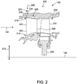
- FIG. 2 is an enlarged schematic view of an exemplary turbine stage 200 of turbine engine 100 (shown in FIG. 1 ).
- Stage 200 includes a plurality of radially-extending stationary airfoils 202 circumferentially-spaced about longitudinal axis 126, and a plurality of radially-extending rotating airfoils 204 that are downstream from stationary airfoils 202 and circumferentially-spaced around longitudinal axis 126.
- the radial direction is indicated by arrow 218.
- Each rotating airfoil 204 is coupled to rotor shaft 112 (shown in FIG. 1 ) via a disk 230 and extends radially outward towards a casing 208.
- each stationary airfoil 202 extends from a first end 216 coupled to an outer endwall 207 of casing 208 of turbine section 108, radially inward to a second end 214 coupled to an inner endwall 209 along a radial direction 218 (the outer endwall 208 and the inner endwall 209 being shown in FIG. 3 ). Additionally, each stationary airfoil 202 extends axially from a leading edge 222 downstream to an opposing trailing edge 224.
- outer endwall 207 and inner endwall 209 define the radial boundaries of a hot gas flow path 232, such that a flow of high temperature combustion gases 124 is channeled therethrough, exposing surfaces of outer endwall 207 and inner endwall 209 to high temperatures and potential thermal stresses and/or thermal degradation.
- an interior cavity or plenum 236 is defined within outer endwall 207 and inner endwall 209 to facilitate internal impingement cooling of an interior surface of outer endwall 207 and inner endwall 209.
- Plenum 236 is in flow communication with a coolant supply channel 233 via a plenum inlet 234 defined in outer endwall 207 and inner endwall 209.
- coolant supply channel 233 channels a cooling fluid 240, such as a flow of pressurized bleed air from compressor section 104 (shown in FIG. 1 ), towards plenum inlet 234.
- cooling fluid 240 may be any suitable fluid other than air.
- stage 200 is a first stage of turbine section 108, and stationary airfoils 202, outer endwall 207, and inner endwall 209 define a first stage turbine nozzle that is immediately downstream from combustor section 106 (shown in FIG. 1 ).
- stage 200 is any other stage of turbine section 108.
- plenum 236 extends axially aftward into outer endwall 207 and inner endwall 209.
- FIG. 3 is a perspective view of stationary airfoil 202, outer endwall 207, and inner endwall 209 and illustrates exemplary cores 300 extending through transparent outer endwall 207 and inner endwall 209.
- FIG. 4 is a perspective top view of stationary airfoil 202, outer endwall 207, and inner endwall 209.
- FIG. 5 is a radial top sectional view of an exemplary outer endwall 207.
- FIG. 6 is a radial top view of an exemplary core 300.
- core 300 is defined in plenum 236 of outer endwall 207 and inner endwall 209 for cooling outer endwall 207 and inner endwall 209. More specifically, cores 300 are disposed within outer endwall 207 and inner endwall 209 to facilitate cooling outer endwall 207 and inner endwall 209 with cooling fluid 240.
- stationary airfoils 202 each include a suction side wall 302 and a pressure side wall 304 (shown in FIG. 5 ). Adjacent stationary airfoils 202, outer endwall 207, and inner endwall 209 define a throat 306 (shown in FIG. 5 ) where a velocity of combustion gases 124 is maximized.
- Outer endwall 207 includes an upstream portion 308 that is upstream from stationary airfoils 202 and a downstream portion 310 that is downstream from stationary airfoils 202.
- Outer endwall 207 also includes a trailing edge 312 adjacent to rotating airfoils 204.
- core 300 is defined within outer endwall 207 downstream from suction side wall 302.
- core 300 may be positioned within outer endwall 207 such that an upstream portion 314 (shown in FIG. 5 ) of core 300 is upstream from throat 306 and a downstream portion 316 of core 300 is downstream from throat 306. Moreover, core 300 may be positioned within outer endwall 207 such that core 300 facilitates cooling outer endwall 207 and trailing edge 312.
- core 300 includes at least one passage 600.
- passage 600 is a serpentine passage that channels cooling fluid 240 adjacent to outer endwall 207 and inner endwall 209 to facilitate cooling outer endwall 207 and inner endwall 209.
- a similar serpentine passage 600 may be used to channel cooling fluid 240 adjacent to inner endwall 209 to facilitate cooling inner endwall 209.
- a "serpentine passage" is a conduit with at least one turn such that the passage winds or twists. That is, the serpentine passage does not have only a substantially straight path from the inlet to the outlet.
- serpentine passage 600 includes at least one inlet 602 and 604, an first inlet portion 606 and a second inlet portion 608 forming a split pass inlet region 610, a first pass 612, a second pass 614, at least one turn 616 disposed between first pass 612 and second pass 614, and at least one outlet 618.
- First pass 612, second pass 614, and turn 616 are oriented such that passage 600 is a serpentine passage.
- serpentine passage 600 includes a plurality of inlets 602 and 604.
- Inlets 602 and 604 receive cooling fluid 240 from coolant supply channel 233 ( FIG. 2 ) and channel cooling fluid 240 to first inlet portion 606 and second inlet portion 608. Specifically, at least one first inlet 602 channels cooling fluid 240 to first inlet portion 606, and at least one second inlet 604 channels cooling fluid 240 to second inlet portion 608.
- FIG. 6 shows a single inlet 602 and 604 extending into each inlet portion 606 and 608. However, each inlet portion 606 and 608 may include a plurality of inlets 602 and 604. Additionally, serpentine passage 600 may include more than two inlet portions 606 and 608.
- first inlets 602 may include two to twenty first inlets 602 channeling cooling fluid 240 to first inlet portion 606, and second inlets 604 may include two to twenty second inlets 604 channeling cooling fluid 240 to second inlet portion 608. More specifically, first inlets 602 may include eight to ten first inlets 602 channeling cooling fluid 240 to first inlet portion 606, and second inlets 604 may include eight to ten second inlets 604 channeling cooling fluid 240 to second inlet portion 608.
- a divider 620 separates first inlet portion 606 from second inlet portion 608 to form split pass inlet region 610.
- Divider 620 reduces a width 622 of split pass inlet region 610 such that a velocity of cooling fluid 240 through split pass inlet region 610 is increased. More specifically, the velocity of cooling fluid 240 through split pass inlet region 610 without divider 620 would decrease because width 622 of split pass inlet region 610 increases downstream from inlets 602 and 604.
- Divider 620 decreases width 622 such that the velocity of cooling fluid 240 either remains constant or increases as cooling fluid 240 is channeled through split pass inlet region 610.
- first inlet portion 606 defines a first width 624
- second inlet portion 608 defines a second width 626.
- First width 624 may be the same or different than second width 626, and first width 624 and second width 626 may be selectively sized to enable a specific volume of cooling fluid 240 to be channeled through passage 600. More specifically, first width 624 and second width 626 may be sized for a specific volumetric flow of cooling fluid 240 such that a heat transfer coefficient of cooling fluid 240 is tuned to the specific heat transfer requirements of outer endwall 207 and/or inner endwall 209.
- First pass 612 extends through outer endwall 207 substantially parallel to trailing edge 312 and second pass 614.
- First pass 612 defines a third width 628 which, along with first width 624 and second width 626, may be selectively sized to enable a specific volumetric flow of cooling fluid 240 to flow therethrough such that a heat transfer coefficient of cooling fluid 240 is tuned to the specific heat transfer requirements of outer endwall 207 and/or inner endwall 209.
- First pass 612 receives cooling fluid 240 from first inlet portion 606 and second inlet portion 608 and channels cooling fluid 240 to turn 616.
- Turn 616 receives cooling fluid 240 from first pass 612 and channels cooling fluid 240 to second pass 614.
- First pass 612, second pass 614, and turn 616 are oriented such that first pass 612 channels cooling fluid 240 in a first direction 630, and second pass 614 channels cooling fluid 240 in a second direction 632 opposite first direction 630.
- Turn 616 changes a direction of flow of cooling fluid 240 from first direction 630 to second direction 632.
- turn 616 is a 180° turn such that first direction 630 is diametrically opposite second direction 632.
- first pass 612, second pass 614, and turn 616 may be oriented such that first pass 612 and second pass 614 have any orientation that enables core 300 to operate as described herein.
- Turn 616 receives cooling fluid 240 from first pass 612, changes the direction of flow of cooling fluid 240, and channels cooling fluid 240 to second pass 614.
- Second pass 614 extends through outer endwall 207 substantially parallel to trailing edge 312 and to first pass 612.
- Second pass 614 defines a fourth width 634 which, along with first width 624, second width 626, and third width 628, may be selectively sized to enable a specific volumetric flow of cooling fluid 240 such that a heat transfer coefficient of cooling fluid 240 is tuned to the specific heat transfer requirements of outer endwall 207 and/or inner endwall 209.
- Second pass 614 receives cooling fluid 240 from turn 616 and channels cooling fluid 240 to outlets 618.
- core 300 includes a single first pass 612, a single second pass 614, and a single turn 616.
- core 300 may include any number of passes and/or turns that enables core 300 to operate as described herein.
- core 300 may include three passes and two turns.
- core 300 may include four passes and three turns.
- Core 300 includes at least one outlet 618 downstream from throat 306. While core 300 may include only a single outlet 618, in the exemplary embodiment, core 300 includes a plurality of outlets 618 that channel cooling fluid from core 300 into hot gas flow path 232.
- core 300 may include at least one first outlet 636 that extends from first pass 612 through outer endwall 207 and into hot gas flow path 232.
- core 300 includes a plurality of first outlets 636, each of which extends from first pass 612 through outer endwall 207 and into hot gas flow path 232. Cooling fluid 240 discharged into hot gas flow path 232 from first outlets 636 may form a cooling film (not shown) on outer endwall 207 that protects outer endwall 207.
- Core 300 may also include at least one second outlet 638 that extends from second pass 614 through outer endwall 207 and into hot gas flow path 232.
- core 300 includes a plurality of second outlets 638, each of which extends from second pass 614 through outer endwall 207 and into hot gas flow path 232.
- Cooling fluid 240 discharged into hot gas flow path 232 from second outlets 638 may form a cooling film (not shown) on outer endwall 207 that facilitates protecting outer endwall 207.
- Core 300 may further include at least one third outlet 640 (shown in FIG. 4 ) that extends from second pass 614 through trailing edge 312 of inner endwall 209 and into hot gas flow path 232.
- core 300 includes a plurality of third outlets 640, each of which extends from second pass 614 through trailing edge 312 of outer endwall 207 and into hot gas flow path 232.
- Cooling fluid 240 discharged into hot gas flow path 232 from third outlets 640 may form a cooling film (not shown) on trailing edge 312 of outer endwall 207 that protects trailing edge 312 of outer endwall 207.
- Core 300 may also include at least one fourth outlet 642 that extends from turn 616 through outer endwall 207 and into hot gas flow path 232.
- core 300 includes a plurality of fourth outlets 642, each of which extends from turn 616 through trailing edge 312 of outer endwall 207 and into hot gas flow path 232.
- Cooling fluid 240 discharged into hot gas flow path 232 from fourth outlets 642 may form a cooling film (not shown) on outer endwall 207 that facilitates protecting outer endwall 207.
- Core 300 may include outlets 218 in any location that enables core 300 to operate as described herein.
- first, second, third, and fourth outlets 636, 638, 640, and 642 may be sized and arranged to facilitate tuning to a specific/desired pressure drop, volumetric flow rate, and/or heat transfer coefficient of cooling fluid 240.
- first outlets 636 may have a first size
- second outlets 638 may be sized with a second size that is smaller than the first size of first outlets 636.
- first outlets 636 form a cooling film (not shown) on outer endwall 207, and second outlets 638 supplement the cooling film with additional cooling fluid 240.
- outlets 636, 638, 640, and 642 facilitate reducing the volumetric flow of cooling fluid 240 through passage 600 and facilitate reducing the pressure drop of cooling fluid 240 through passage 600. Accordingly, the size, shape, and position of first, second, third, and fourth outlets 636, 638, 640, and 642 may be sized and arranged to facilitate tuning the pressure drop, the volumetric flow rate, and/or the heat transfer coefficient of cooling fluid 240.
- first pass 612 and second pass 614 each include a plurality of turbulators or ridges 644 that create turbulence within first pass 612 and second pass 614.
- turbulators 644 create turbulent flow within cooling fluid 240 to facilitate increasing the heat transfer coefficient of cooling fluid 240 within first pass 612 and second pass 614. Increasing the heat transfer coefficient increases the overall heat transfer between cooling fluid 240 and outer endwall 207.
- turbulators 644 have a height (not shown) that is about 10% that of third width 628 and fourth width 634. However, turbulators 644 may have any other height that enables core 300 to operate as described herein.
- core 300 includes a plurality of hollow core ties 646 that extend from either first inlet portion 606 to second inlet portion 608 or first pass 612 to second pass 614.
- core 300 includes at least one first core tie 648 that extends from first inlet portion 606 to second inlet portion 608 and at least one second core tie 650 extending from first pass 612 to second pass 614.
- core 300 includes a single first core tie 648 and a plurality of second core ties 650.
- First and second core ties 648 and 650 which define fluid passages therein, replenish downstream portions of passage 600 with cooling fluid 240.
- cooling fluid 240 As cooling fluid 240 is channeled through passage 600, a temperature of cooling fluid 240 increases which facilitates decreasing the heat transfer coefficient of cooling fluid 240 and decreasing the overall heat transfer between cooling fluid 240 and outer endwall 207.
- Core ties 646 are "short cuts" that channel cooling fluid 240 from upstream portions of passage 600 to downstream portions of passage 600 without heat transfer between cooling fluid 240 and outer endwall 207. As such, cooling fluid 240 that is channeled through core ties 646 has a lower temperature than cooling fluid 240 that was channeled through first pass 612, second pass 614, and turn 616.
- core ties 646 replenish downstream portions of passage 600 with cooling fluid 240 that has a lower temperature, which facilitates increasing the heat transfer coefficient of cooling fluid 240 and overall heat transfer between cooling fluid 240 and outer endwall 207.
- Core ties 646 may also be used as inspection ports to inspect core 300.
- inlets 602 and 604 receive cooling fluid 240 from coolant supply channel 233 and channel cooling fluid 240 to first inlet portion 606 and second inlet portion 608.
- First inlet portion 606 channels a portion of cooling fluid 240 through first core tie 648 to replenish second inlet portion 608.
- First inlet portion 606 and second inlet portion 608 merge into first pass 612 and each channels cooling fluid 240 into first pass 612.
- First pass 612 channels a portion of cooling fluid 240 through second core ties 650 to replenish second pass 614 and channels another portion of cooling fluid 240 to turn 616.
- First pass 612 also channels a portion of cooling fluid through first outlet 636 into hot gas path 232 to form a cooling film on outer endwall 207.
- Turn 616 channels a portion of cooling fluid 240 through fourth outlet 642 into hot gas path 232 to form the cooling film on outer endwall 207 and channels the remaining cooling fluid 240 to second pass 614.
- Second pass 614 channels cooling fluid 240 through second and third outlets 638 and 640 to replenish the cooling film and to form a cooling film on trailing edge 312.
- Cooling fluid 240 exchanges heat with outer endwall 207 as it is channeled through passage 600. As such, cooling fluid 240 facilitates cooling outer endwall 207 from within core 300 and forms a protective cooling film that protects outer endwall 207.
- the serpentine configuration of passage 600 enables cooling fluid 240 to cool a larger area of outer endwall 207, thus increasing the overall heat transfer between cooling fluid 240 and outer endwall 207. Additionally, the serpentine orientation of passage 600 enables cooling fluid 240 to have a lower pressure that is approximately equal to the pressure of combustion gases 124 at throat 306. Furthermore, widths 624, 626, 628, and 634 are sized to tune the pressure drop of cooling fluid 240 through passage 600 and to facilitate increasing the overall heat transfer between cooling fluid 240 and outer endwall 207. Moreover, outlets 618 channel cooling fluid 240 into hot gas path 232 to protect outer endwall 207 by forming a cooling film. Additionally, core ties 646 replenish downstream portions of passage 600 with cooling fluid 240. Accordingly, the arrangement of core 300 increases the overall heat transfer between cooling fluid 240 and outer endwall 207.
- FIGS. 3 through 6 have described core 300 and its features in connection with outer endwall 207, it should be understood that the core 300 may be employed with similar features in inner endwall 209 to achieve similar results and benefits.
- FIG. 7 is a flow diagram of an exemplary method 700 of cooling a component of a rotary machine.
- method 700 includes inserting 702 a core into a plenum within the component.
- the core includes a passage including an inlet portion, at least one first pass, at least one second pass, at least one turn between respective first pass(es) and second pass(es).
- the inlet portion includes a divider that separates a first inlet portion from a second inlet portion, such that the inlet portion is a split pass inlet.
- Method 700 also includes channeling 704 a flow of cooling fluid into the first inlet portion and the second inlet portion.
- Method 700 further includes channeling 706 the flow of cooling fluid from the first inlet portion and the second inlet portion into the at least one first pass.
- the flow of cooling fluid from the first inlet portion merges with the flow of cooling fluid from the second inlet portion, and the at least one first pass channels the flow of cooling fluid in a first direction.
- Method 700 also includes channeling 708 the flow of cooling fluid from the at least one first pass into the at least one turn.
- the at least one turn changes a direction of flow of the cooling fluid from the first direction to a second direction opposite the first direction.
- Method 700 further includes channeling 710 the flow of cooling fluid from the at least one turn into the at least one second pass.
- the at least one first pass, the at least one second pass, and the at least one turn are arranged such that the passage is a serpentine passage.
- a rotary component includes an outer endwall formed in a nozzle of a turbine section within the rotary machine.
- the outer endwall includes a core for use in cooling the outer endwall.
- the core includes a serpentine passage including an inlet portion, a first pass, a second pass, and a turn between the first pass and the second pass.
- the inlet portion includes a divider that separates a first inlet portion from a second inlet portion, such that a split pass inlet is defined.
- the first pass, the second pass, and the turn include a plurality of outlets, each of which channels cooling fluid from the core into the hot gas path to form a cooling film on the outer endwall.
- a plurality of hollow core ties channels cooling fluid from an upstream portion of the core to a downstream portion of the core to enable the downstream portions to be replenished with lower temperature cooling fluid.
- cooling fluid is channeled through the first pass, the second pass, and the turn to facilitate convective cooling of the outer endwall from within the core.
- the serpentine configuration of the first pass, the second pass, and the turn enables the cooling fluid to convectively cool a larger area of the outer endwall, thus increasing the overall heat transfer between the cooling fluid and the outer endwall. Additionally, the serpentine configuration enables the cooling fluid to circulate with a lower pressure that is substantially equal to the pressure of combustion gases at a throat of the nozzle.
- a width of each of the first pass, the second pass, and the turn is selected to facilitate modification of, or tune, the pressure drop of the cooling fluid through the first pass, the second pass, and the turn and to increase the overall heat transfer between the cooling fluid and the outer endwall.
- the outlets channel cooling fluid into the hot gas path to facilitate forming a cooling film across the stator endwall.
- the core ties replenish downstream portions of the core with cooling fluid.
- an exemplary technical effect of the systems and methods described herein includes at least one of: (a) removing heat from a rotary machine component; (b) increasing the heat transfer coefficient of a cooling fluid; (c) increasing the overall heat transfer between the cooling fluid and the rotary machine component; and (d) increasing rotary machine efficiency.
- Exemplary embodiments of systems and methods for cooling portions of a hot gas path of a rotary machine are described above in detail.
- the methods and systems are not limited to the specific embodiments described herein, but rather, components of systems and/or steps of the methods may be utilized independently and separately from other components and/or steps described herein.
- the method may also be used in combination with other turbine components, and are not limited to practice only with the portions of the hot gas path of the rotary machine as described herein. Rather, the exemplary embodiment can be implemented and utilized in connection with many other rotary machine applications.
Landscapes
- Engineering & Computer Science (AREA)
- Mechanical Engineering (AREA)
- General Engineering & Computer Science (AREA)
- Chemical & Material Sciences (AREA)
- Combustion & Propulsion (AREA)
- Physics & Mathematics (AREA)
- Fluid Mechanics (AREA)
- Turbine Rotor Nozzle Sealing (AREA)
- Iron Core Of Rotating Electric Machines (AREA)
Applications Claiming Priority (1)
| Application Number | Priority Date | Filing Date | Title |
|---|---|---|---|
| US16/875,604 US11174788B1 (en) | 2020-05-15 | 2020-05-15 | Systems and methods for cooling an endwall in a rotary machine |
Publications (1)
| Publication Number | Publication Date |
|---|---|
| EP3916200A1 true EP3916200A1 (fr) | 2021-12-01 |
Family
ID=75728634
Family Applications (1)
| Application Number | Title | Priority Date | Filing Date |
|---|---|---|---|
| EP21170808.6A Pending EP3916200A1 (fr) | 2020-05-15 | 2021-04-27 | Systèmes et procédés de refroidissement d'une paroi d'extrémité dans une machine rotative |
Country Status (4)
| Country | Link |
|---|---|
| US (1) | US11174788B1 (fr) |
| EP (1) | EP3916200A1 (fr) |
| JP (1) | JP7774974B2 (fr) |
| CN (1) | CN113669119B (fr) |
Families Citing this family (1)
| Publication number | Priority date | Publication date | Assignee | Title |
|---|---|---|---|---|
| US12173619B2 (en) | 2022-05-02 | 2024-12-24 | Siemens Energy Global GmbH & Co. KG | Turbine component having platform cooling circuit |
Citations (7)
| Publication number | Priority date | Publication date | Assignee | Title |
|---|---|---|---|---|
| US5545002A (en) * | 1984-11-29 | 1996-08-13 | Societe Nationale D'etude Et De Construction De Moteurs D'aviation S.N.E.C.M.A. | Stator vane mounting platform |
| EP1865149A2 (fr) * | 2006-06-07 | 2007-12-12 | General Electric Company | Circuit de refroidissement à serpentin et procédé de refroidissement d'un anneau |
| US20120107134A1 (en) * | 2010-10-29 | 2012-05-03 | General Electric Company | Apparatus and methods for cooling platform regions of turbine rotor blades |
| EP2489838A2 (fr) * | 2011-02-17 | 2012-08-22 | Rolls-Royce plc | Composant refroidi pour turbine d'un moteur de turbine à gaz |
| US20130171005A1 (en) * | 2011-12-30 | 2013-07-04 | Scott Edmond Ellis | Turbine rotor blade platform cooling |
| US20140047843A1 (en) * | 2012-08-15 | 2014-02-20 | Michael Leslie Clyde Papple | Platform cooling circuit for a gas turbine engine component |
| EP3156612A1 (fr) * | 2015-10-12 | 2017-04-19 | United Technologies Corporation | Composants de moteur à turbine à gaz, ensembles de scellement d'air extérieur d'aube et segments de joint d'air extérieur d'aube correspondants |
Family Cites Families (22)
| Publication number | Priority date | Publication date | Assignee | Title |
|---|---|---|---|---|
| DE4328294A1 (de) * | 1993-08-23 | 1995-03-02 | Abb Management Ag | Verfahren zur Kühlung eines Bauteils sowie Vorrichtung zur Durchführung des Verfahrens |
| US6170264B1 (en) | 1997-09-22 | 2001-01-09 | Clean Energy Systems, Inc. | Hydrocarbon combustion power generation system with CO2 sequestration |
| JP3727701B2 (ja) * | 1995-12-27 | 2005-12-14 | 三菱重工業株式会社 | ガスタービン翼の冷却装置 |
| US6241467B1 (en) * | 1999-08-02 | 2001-06-05 | United Technologies Corporation | Stator vane for a rotary machine |
| US6254333B1 (en) * | 1999-08-02 | 2001-07-03 | United Technologies Corporation | Method for forming a cooling passage and for cooling a turbine section of a rotary machine |
| US6905302B2 (en) * | 2003-09-17 | 2005-06-14 | General Electric Company | Network cooled coated wall |
| JP2009128509A (ja) | 2007-11-21 | 2009-06-11 | Nitto Denko Corp | 液晶表示装置 |
| US8011881B1 (en) * | 2008-01-21 | 2011-09-06 | Florida Turbine Technologies, Inc. | Turbine vane with serpentine cooling |
| CN101307915B (zh) | 2008-06-24 | 2010-06-02 | 北京航空航天大学 | 一种燃用乙醇燃料的燃气轮机预蒸发燃烧室 |
| CN101435585B (zh) | 2008-11-28 | 2010-10-13 | 北京大学 | 一种燃气轮机组合式燃油蒸发雾化燃烧装置 |
| EP2407639A1 (fr) * | 2010-07-15 | 2012-01-18 | Siemens Aktiengesellschaft | Pièce de plateforme pour supporter une aube de guidage de buses pour une turbine à gaz |
| US8647064B2 (en) * | 2010-08-09 | 2014-02-11 | General Electric Company | Bucket assembly cooling apparatus and method for forming the bucket assembly |
| US8794921B2 (en) * | 2010-09-30 | 2014-08-05 | General Electric Company | Apparatus and methods for cooling platform regions of turbine rotor blades |
| US9416665B2 (en) * | 2012-02-15 | 2016-08-16 | United Technologies Corporation | Cooling hole with enhanced flow attachment |
| US9109454B2 (en) * | 2012-03-01 | 2015-08-18 | General Electric Company | Turbine bucket with pressure side cooling |
| US9021816B2 (en) * | 2012-07-02 | 2015-05-05 | United Technologies Corporation | Gas turbine engine turbine vane platform core |
| US9194237B2 (en) * | 2012-09-10 | 2015-11-24 | General Electric Company | Serpentine cooling of nozzle endwall |
| JP5554425B2 (ja) * | 2013-02-12 | 2014-07-23 | 三菱重工業株式会社 | タービン翼 |
| US9810084B1 (en) * | 2015-02-06 | 2017-11-07 | United Technologies Corporation | Gas turbine engine turbine vane baffle and serpentine cooling passage |
| EP3354850A1 (fr) * | 2017-01-31 | 2018-08-01 | Siemens Aktiengesellschaft | Aube ou ailette d'une turbine à gaz |
| US11021967B2 (en) * | 2017-04-03 | 2021-06-01 | General Electric Company | Turbine engine component with a core tie hole |
| US10323520B2 (en) * | 2017-06-13 | 2019-06-18 | General Electric Company | Platform cooling arrangement in a turbine rotor blade |
-
2020
- 2020-05-15 US US16/875,604 patent/US11174788B1/en active Active
-
2021
- 2021-04-14 CN CN202110410714.XA patent/CN113669119B/zh active Active
- 2021-04-19 JP JP2021070710A patent/JP7774974B2/ja active Active
- 2021-04-27 EP EP21170808.6A patent/EP3916200A1/fr active Pending
Patent Citations (7)
| Publication number | Priority date | Publication date | Assignee | Title |
|---|---|---|---|---|
| US5545002A (en) * | 1984-11-29 | 1996-08-13 | Societe Nationale D'etude Et De Construction De Moteurs D'aviation S.N.E.C.M.A. | Stator vane mounting platform |
| EP1865149A2 (fr) * | 2006-06-07 | 2007-12-12 | General Electric Company | Circuit de refroidissement à serpentin et procédé de refroidissement d'un anneau |
| US20120107134A1 (en) * | 2010-10-29 | 2012-05-03 | General Electric Company | Apparatus and methods for cooling platform regions of turbine rotor blades |
| EP2489838A2 (fr) * | 2011-02-17 | 2012-08-22 | Rolls-Royce plc | Composant refroidi pour turbine d'un moteur de turbine à gaz |
| US20130171005A1 (en) * | 2011-12-30 | 2013-07-04 | Scott Edmond Ellis | Turbine rotor blade platform cooling |
| US20140047843A1 (en) * | 2012-08-15 | 2014-02-20 | Michael Leslie Clyde Papple | Platform cooling circuit for a gas turbine engine component |
| EP3156612A1 (fr) * | 2015-10-12 | 2017-04-19 | United Technologies Corporation | Composants de moteur à turbine à gaz, ensembles de scellement d'air extérieur d'aube et segments de joint d'air extérieur d'aube correspondants |
Also Published As
| Publication number | Publication date |
|---|---|
| JP7774974B2 (ja) | 2025-11-25 |
| US20210355879A1 (en) | 2021-11-18 |
| US11174788B1 (en) | 2021-11-16 |
| CN113669119B (zh) | 2025-06-27 |
| JP2021179208A (ja) | 2021-11-18 |
| CN113669119A (zh) | 2021-11-19 |
Similar Documents
| Publication | Publication Date | Title |
|---|---|---|
| US12065946B2 (en) | Blade with tip rail cooling | |
| US10577944B2 (en) | Engine component with hollow turbulators | |
| US10830051B2 (en) | Engine component with film cooling | |
| US10753207B2 (en) | Airfoil with tip rail cooling | |
| US20170107825A1 (en) | Turbine blade | |
| US10443397B2 (en) | Impingement system for an airfoil | |
| US10830057B2 (en) | Airfoil with tip rail cooling | |
| US10830060B2 (en) | Engine component with flow enhancer | |
| US10563518B2 (en) | Gas turbine engine trailing edge ejection holes | |
| US10408062B2 (en) | Impingement system for an airfoil | |
| US10718217B2 (en) | Engine component with cooling passages | |
| US10711620B1 (en) | Insert system for an airfoil and method of installing same | |
| US11174788B1 (en) | Systems and methods for cooling an endwall in a rotary machine | |
| US10808547B2 (en) | Turbine engine airfoil with cooling | |
| US10612389B2 (en) | Engine component with porous section | |
| US20180156041A1 (en) | Engine with chevron pin bank | |
| US9376918B2 (en) | Aerofoil cooling arrangement | |
| US20230417150A1 (en) | Augmented cooling for tip clearance optimization | |
| US10364685B2 (en) | Impingement system for an airfoil |
Legal Events
| Date | Code | Title | Description |
|---|---|---|---|
| PUAI | Public reference made under article 153(3) epc to a published international application that has entered the european phase |
Free format text: ORIGINAL CODE: 0009012 |
|
| STAA | Information on the status of an ep patent application or granted ep patent |
Free format text: STATUS: THE APPLICATION HAS BEEN PUBLISHED |
|
| AK | Designated contracting states |
Kind code of ref document: A1 Designated state(s): AL AT BE BG CH CY CZ DE DK EE ES FI FR GB GR HR HU IE IS IT LI LT LU LV MC MK MT NL NO PL PT RO RS SE SI SK SM TR |
|
| B565 | Issuance of search results under rule 164(2) epc |
Effective date: 20211104 |
|
| STAA | Information on the status of an ep patent application or granted ep patent |
Free format text: STATUS: REQUEST FOR EXAMINATION WAS MADE |
|
| 17P | Request for examination filed |
Effective date: 20220531 |
|
| RBV | Designated contracting states (corrected) |
Designated state(s): AL AT BE BG CH CY CZ DE DK EE ES FI FR GB GR HR HU IE IS IT LI LT LU LV MC MK MT NL NO PL PT RO RS SE SI SK SM TR |
|
| STAA | Information on the status of an ep patent application or granted ep patent |
Free format text: STATUS: EXAMINATION IS IN PROGRESS |
|
| 17Q | First examination report despatched |
Effective date: 20230906 |
|
| RAP1 | Party data changed (applicant data changed or rights of an application transferred) |
Owner name: GENERAL ELECTRIC TECHNOLOGY GMBH |
|
| RAP3 | Party data changed (applicant data changed or rights of an application transferred) |
Owner name: GE VERNOVA TECHNOLOGY GMBH |