EP3916261A1 - Bremsvorrichtung und spaltverstellmechanismus für eine bremsvorrichtung - Google Patents
Bremsvorrichtung und spaltverstellmechanismus für eine bremsvorrichtung Download PDFInfo
- Publication number
- EP3916261A1 EP3916261A1 EP21170072.9A EP21170072A EP3916261A1 EP 3916261 A1 EP3916261 A1 EP 3916261A1 EP 21170072 A EP21170072 A EP 21170072A EP 3916261 A1 EP3916261 A1 EP 3916261A1
- Authority
- EP
- European Patent Office
- Prior art keywords
- screw portion
- female screw
- male screw
- brake device
- width direction
- Prior art date
- Legal status (The legal status is an assumption and is not a legal conclusion. Google has not performed a legal analysis and makes no representation as to the accuracy of the status listed.)
- Granted
Links
Images



Classifications
-
- F—MECHANICAL ENGINEERING; LIGHTING; HEATING; WEAPONS; BLASTING
- F16—ENGINEERING ELEMENTS AND UNITS; GENERAL MEASURES FOR PRODUCING AND MAINTAINING EFFECTIVE FUNCTIONING OF MACHINES OR INSTALLATIONS; THERMAL INSULATION IN GENERAL
- F16D—COUPLINGS FOR TRANSMITTING ROTATION; CLUTCHES; BRAKES
- F16D55/00—Brakes with substantially-radial braking surfaces pressed together in axial direction, e.g. disc brakes
- F16D55/02—Brakes with substantially-radial braking surfaces pressed together in axial direction, e.g. disc brakes with axially-movable discs or pads pressed against axially-located rotating members
- F16D55/22—Brakes with substantially-radial braking surfaces pressed together in axial direction, e.g. disc brakes with axially-movable discs or pads pressed against axially-located rotating members by clamping an axially-located rotating disc between movable braking members, e.g. movable brake discs or brake pads
- F16D55/224—Brakes with substantially-radial braking surfaces pressed together in axial direction, e.g. disc brakes with axially-movable discs or pads pressed against axially-located rotating members by clamping an axially-located rotating disc between movable braking members, e.g. movable brake discs or brake pads with a common actuating member for the braking members
- F16D55/2245—Brakes with substantially-radial braking surfaces pressed together in axial direction, e.g. disc brakes with axially-movable discs or pads pressed against axially-located rotating members by clamping an axially-located rotating disc between movable braking members, e.g. movable brake discs or brake pads with a common actuating member for the braking members in which the common actuating member acts on two levers carrying the braking members, e.g. tong-type brakes
-
- F—MECHANICAL ENGINEERING; LIGHTING; HEATING; WEAPONS; BLASTING
- F16—ENGINEERING ELEMENTS AND UNITS; GENERAL MEASURES FOR PRODUCING AND MAINTAINING EFFECTIVE FUNCTIONING OF MACHINES OR INSTALLATIONS; THERMAL INSULATION IN GENERAL
- F16D—COUPLINGS FOR TRANSMITTING ROTATION; CLUTCHES; BRAKES
- F16D55/00—Brakes with substantially-radial braking surfaces pressed together in axial direction, e.g. disc brakes
- F16D55/02—Brakes with substantially-radial braking surfaces pressed together in axial direction, e.g. disc brakes with axially-movable discs or pads pressed against axially-located rotating members
- F16D55/22—Brakes with substantially-radial braking surfaces pressed together in axial direction, e.g. disc brakes with axially-movable discs or pads pressed against axially-located rotating members by clamping an axially-located rotating disc between movable braking members, e.g. movable brake discs or brake pads
- F16D55/228—Brakes with substantially-radial braking surfaces pressed together in axial direction, e.g. disc brakes with axially-movable discs or pads pressed against axially-located rotating members by clamping an axially-located rotating disc between movable braking members, e.g. movable brake discs or brake pads with a separate actuating member for each side
-
- B—PERFORMING OPERATIONS; TRANSPORTING
- B60—VEHICLES IN GENERAL
- B60T—VEHICLE BRAKE CONTROL SYSTEMS OR PARTS THEREOF; BRAKE CONTROL SYSTEMS OR PARTS THEREOF, IN GENERAL; ARRANGEMENT OF BRAKING ELEMENTS ON VEHICLES IN GENERAL; PORTABLE DEVICES FOR PREVENTING UNWANTED MOVEMENT OF VEHICLES; VEHICLE MODIFICATIONS TO FACILITATE COOLING OF BRAKES
- B60T17/00—Component parts, details, or accessories of power brake systems not covered by groups B60T8/00, B60T13/00 or B60T15/00, or presenting other characteristic features
- B60T17/18—Safety devices; Monitoring
- B60T17/22—Devices for monitoring or checking brake systems; Signal devices
- B60T17/228—Devices for monitoring or checking brake systems; Signal devices for railway vehicles
-
- B—PERFORMING OPERATIONS; TRANSPORTING
- B61—RAILWAYS
- B61H—BRAKES OR OTHER RETARDING DEVICES SPECIALLY ADAPTED FOR RAIL VEHICLES; ARRANGEMENT OR DISPOSITION THEREOF IN RAIL VEHICLES
- B61H5/00—Applications or arrangements of brakes with substantially radial braking surfaces pressed together in axial direction, e.g. disc brakes
-
- F—MECHANICAL ENGINEERING; LIGHTING; HEATING; WEAPONS; BLASTING
- F16—ENGINEERING ELEMENTS AND UNITS; GENERAL MEASURES FOR PRODUCING AND MAINTAINING EFFECTIVE FUNCTIONING OF MACHINES OR INSTALLATIONS; THERMAL INSULATION IN GENERAL
- F16D—COUPLINGS FOR TRANSMITTING ROTATION; CLUTCHES; BRAKES
- F16D65/00—Parts or details
- F16D65/14—Actuating mechanisms for brakes; Means for initiating operation at a predetermined position
- F16D65/16—Actuating mechanisms for brakes; Means for initiating operation at a predetermined position arranged in or on the brake
-
- F—MECHANICAL ENGINEERING; LIGHTING; HEATING; WEAPONS; BLASTING
- F16—ENGINEERING ELEMENTS AND UNITS; GENERAL MEASURES FOR PRODUCING AND MAINTAINING EFFECTIVE FUNCTIONING OF MACHINES OR INSTALLATIONS; THERMAL INSULATION IN GENERAL
- F16D—COUPLINGS FOR TRANSMITTING ROTATION; CLUTCHES; BRAKES
- F16D65/00—Parts or details
- F16D65/38—Slack adjusters
- F16D65/40—Slack adjusters mechanical
- F16D65/42—Slack adjusters mechanical non-automatic
- F16D65/46—Slack adjusters mechanical non-automatic with screw-thread and nut
-
- F—MECHANICAL ENGINEERING; LIGHTING; HEATING; WEAPONS; BLASTING
- F16—ENGINEERING ELEMENTS AND UNITS; GENERAL MEASURES FOR PRODUCING AND MAINTAINING EFFECTIVE FUNCTIONING OF MACHINES OR INSTALLATIONS; THERMAL INSULATION IN GENERAL
- F16D—COUPLINGS FOR TRANSMITTING ROTATION; CLUTCHES; BRAKES
- F16D2121/00—Type of actuator operation force
- F16D2121/02—Fluid pressure
- F16D2121/04—Fluid pressure acting on a piston-type actuator, e.g. for liquid pressure
-
- F—MECHANICAL ENGINEERING; LIGHTING; HEATING; WEAPONS; BLASTING
- F16—ENGINEERING ELEMENTS AND UNITS; GENERAL MEASURES FOR PRODUCING AND MAINTAINING EFFECTIVE FUNCTIONING OF MACHINES OR INSTALLATIONS; THERMAL INSULATION IN GENERAL
- F16D—COUPLINGS FOR TRANSMITTING ROTATION; CLUTCHES; BRAKES
- F16D65/00—Parts or details
- F16D65/38—Slack adjusters
- F16D65/40—Slack adjusters mechanical
- F16D65/52—Slack adjusters mechanical self-acting in one direction for adjusting excessive play
- F16D65/56—Slack adjusters mechanical self-acting in one direction for adjusting excessive play with screw-thread and nut
- F16D65/567—Slack adjusters mechanical self-acting in one direction for adjusting excessive play with screw-thread and nut for mounting on a disc brake
Definitions
- the present invention relates to a brake device and a gap adjusting mechanism for a brake device.
- the brake device includes a pair of rotating arms for sandwiching a disc fixedly attached to an axle. Each of the rotating arms has at a tip end portion thereof an attaching portion mounted thereto. A brake pad is fixedly attached to the attaching portion. Between the brake pads supported on the tip end portions of the rotating arms, the disc rotatable with a wheel is provided. Between the base end portions of the rotating arms, a gap adjusting mechanism for adjusting the distance between the disc and the brake pads is provided. The gap adjusting mechanism is coupled to the base end portion of each of the rotating arms.
- One of the rotating arms is coupled to a piston provided within a cylinder, and the pair of rotating arms is rotated by a driving force provided from the piston, which is to be driven by an air pressure.
- the brake pads supported on the tip end portions of the rotating arms touch the disc. As the brake pads touch the disc, they gradually wear off. This increases the distance between the brake pads and the disc.
- the gap adjusting mechanism provided in the brake device disclosed in the '423 Publication includes a male screw part having external threads and positioned between the base end portions of the rotating arms and a tubular female screw part having internal threads and for receiving the male screw part. If the piston moves by a predetermined distance or more, the driving force provided from the piston can be transferred to the female screw part of the gap adjusting mechanism. The driving force provided from the piston rotates the female screw part relative to the male screw part in a certain direction, so that the distance between the base end portions of the rotating arms increases. This in turn decreases the distance between the tip end portions of the rotating arms, so that the distance between the disc and the brake pads decreases.
- the reaction force resulting from the braking applied by the brake device, the vibration of the railroad vehicles and other factors may apply such a force to the female screw part that the female screw part is rotated relative to the male screw part in the opposite direction. If the female screw part is rotated relative to the male screw part in the opposite direction, the distance between the base end portions of the rotating arms may possibly decrease. This may in turn change the distance between the disc and the brake pads.
- the present invention is made in light of the above and is designed to prevent an unexpected reduction in the distance between the base end portions of the rotating arms.
- a brake device that includes a pair of rotating arms, where the rotating arms each have a friction member attached on a tip end portion thereof, where the friction members are configured to sandwich a brake disc when at least one of the rotating arms rotates, and a gap adjusting mechanism connected to base end portions of the rotating arms that are positioned opposite to the tip end portions, where each of the rotating arms has a rotation center between the base and tip end portions thereof, where the gap adjusting mechanism is configured to adjust a distance between the base end portions of the rotating arms.
- the gap adjusting mechanism includes a male screw portion, a female screw portion for receiving the male screw portion fitted therein, and an input member for allowing a force fed from a piston provided within a cylinder to rotate a first one of the male screw portion and the female screw portion relative to a second one of the male screw portion and the female screw portion in one direction.
- the gap adjusting mechanism further includes a one-way clutch for allowing the first one of the male screw portion and the female screw portion to rotate relative to the second one of the male screw portion and the female screw portion in the one direction and preventing the first one of the male screw portion and the female screw portion from rotating relative to the second one of the male screw portion and the female screw portion in the other direction.
- the above design can prevent a reduction in the distance between the base end portions of the rotating arms even if vibration or other factors may apply a force such that the first one of the male screw portion and the female screw portion rotates relative to the second one of the male screw portion and the female screw portion in the other direction.
- the brake device described above may include a holder member holding the first one of the male screw portion and the female screw portion and being fixedly attached to one of the rotating arms.
- the one-way clutch may be interposed between the first one of the male screw portion and the female screw portion and the holder member.
- the first one of the male screw portion and the female screw portion may have a protrusion protruding radially outside, and the protrusion may have a contact surface facing a contact-target surface of the holder member and being configured to contact the contact-target surface of the holder member in an axial direction of the male and female screw portions.
- the holder member may have a first accommodating space for accommodating the one-way clutch therein and a second accommodating space connected to the first accommodating space and for accommodating the protrusion therein, an inner diameter of the second accommodating space may be greater than an inner diameter of the first accommodating space, and the contact-target surface may be a step surface demarcating a boundary between the first accommodating space and the second accommodating space.
- the gap adjusting mechanism may include an elastic member for urging the protrusion such that the contact surface contacts the contact-target surface.
- the second one of the male screw portion and the female screw portion may have an adjusting portion at an end portion thereof for rotating the second one of the male screw portion and the female screw portion relative to the first one of the male screw portion and the female screw portion.
- the adjusting portion is one of adjusting portions provided in the second one of the male screw portion and the female screw portion at respective end portions thereof.
- the adjusting portions may include a first adjusting portion and a second adjusting portion
- the male screw portion may include a screw body to be fitted in the female screw portion and a rod fixedly attached to and aligned with the screw body and protruding beyond one of axial ends of the screw body.
- the first adjusting portion may be provided on an axial end of the screw body that is positioned opposite to the rod
- the second adjusting portion may be provided on an axial end of the rod that is positioned opposite to the screw body.
- the first one of the male screw portion and the female screw portion may be the female screw portion and the second one of the male screw portion and the female screw portion may be the male screw portion.
- the brake device includes a pair of rotating arms, where the rotating arms each have a friction member attached on a tip end portion thereof, where the friction members are configured to sandwich a brake disc when at least one of the rotating arms rotates.
- the gap adjusting mechanism is connected to base end portions of the rotating arms that are positioned opposite to the tip end portions, each of the rotating arms (40) has a rotation center between the base and tip end portions thereof, and the gap adjusting mechanism is configured to adjust a distance between the base end portions of the rotating arms.
- the gap adjusting mechanism includes a male screw portion, a female screw portion for receiving the male screw portion fitted therein, and an input member for allowing a force fed from a piston provided within a cylinder to rotate a first one of the male screw portion and the female screw portion relative to a second one of the male screw portion and the female screw portion in one direction.
- the gap adjusting mechanism further includes a one-way clutch for allowing the first one of the male screw portion and the female screw portion to rotate relative to the second one of the male screw portion and the female screw portion in the one direction and preventing the first one of the male screw portion and the female screw portion from rotating relative to the second one of the male screw portion and the female screw portion in the other direction.
- the above design can prevent a reduction in the distance between the base end portions of the rotating arms even if vibration or other factors may apply a force such that the first one of the male screw portion and the female screw portion is rotated relative to the second one of the male screw portion and the female screw portion in the other direction.
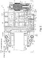
- the following describes one embodiment of a brake device attached to a railroad vehicle and a gap adjusting mechanism for the brake device with reference to Figs. 1 to 6 .
- a brake device 10 is a caliper brake device including a pair of brake pads 90.
- the brake device 10 is designed to brake rotation of a disc 95, which is rotatable integrally with the wheel of the railroad vehicle, by sandwiching the disk 95 between the brake pads 90.
- the brake device 10 and the disc 95 together constitute a disc brake device.
- the brake device 10 includes a first cylinder 11 having a columnar shape.
- the central axis of the first cylinder 11 extends along the width direction of the vehicle.
- the first cylinder 11 has a circular cylindrical inner space defined therein.
- the first cylinder 11 has an end wall 11C on the H side in the vehicle width direction (the lower side in Fig. 2 ), which has a through hole 11A formed therein penetrating the end wall 11C in the thickness direction.
- the through hole 11A is positioned at the center of the end wall 11C of the first cylinder 11, which is on the H side in the vehicle width direction.
- the first cylinder 11 also has an end wall 11D on the I side in the vehicle width direction (the upper side in Fig.
- the first cylinder 11 is fixedly attached to a caliper body 86A. As shown in Fig. 1 , the caliper body 86A is supported on a bracket 86B for attaching the brake device 10 onto a bogie of the railroad vehicle.
- the bracket 86B has a plurality of bolt holes 87 formed therein. Bolts are inserted through the bolt holes 87 to secure the bracket 86B onto the bogie of the railroad vehicle.
- the first cylinder 11 has a first piston 12 disposed therein, and the first piston 12 is linearly movable along the axial direction of the first cylinder 11.
- the first piston 12 is substantially shaped like a disc.
- the outer diameter of the first piston 12 is substantially equal to the inner diameter of the first cylinder 11.
- the first piston 12 partitions the inner space of the first cylinder 11 into two parts next to each other in the axial direction of the first cylinder 11.
- a columnar output shaft 13 extends toward the H side in the vehicle width direction.
- the first piston 12 and the output shaft 13 are formed in one piece with each other.
- the output shaft 13 is linearly movable along the axial direction of the first cylinder 11 together with the first piston 12.
- the tip end portion of the output shaft 13 passes through the through hole 11A formed in the first cylinder 11 to reach the outside of the first cylinder 11.
- the output shaft 13 has an insertion hole 13A formed therein.
- the insertion hole 13A penetrates the tip end portion of the output shaft 13 in the direction orthogonal to the central axis of the output shaft 13.
- a rotational body 13B substantially shaped like a circular column is rotatably supported on the output shaft 13 at a position between the insertion hole 13A and the tip end.
- the central axis of the rotational body 13B extends in the vehicle front-rear direction (the direction orthogonal to the plane of the paper in Fig. 4 ).
- a radially outer portion of the rotational body 13B protrudes beyond the tip-side end surface of the output shaft 13 toward the H side in the vehicle width direction.
- the rotational body 13B is positioned on the lower side in the vehicle top-bottom direction (the lower side in Fig. 4 ).
- the first cylinder 11 has a first spring 14 disposed therein.
- the first spring 14 is configured to urge the first piston 12 in a direction from the H side toward the I side in the vehicle width direction within the first cylinder 11.
- the first spring 14 is positioned between the first piston 12 and the end wall 11C of the first cylinder 11, which is positioned on the H side in the vehicle width direction.
- a space 11E is defined on the I side in the vehicle width direction with respect to the first piston 12 and receives compressed air fed from an air source, which is not shown.
- a columnar second cylinder 21 is fixedly attached on the end wall 11D of the first cylinder 11, which is positioned on the I side in the vehicle width direction.
- the central axis of the second cylinder 21 is aligned with the central axis of the first cylinder 11.
- the second cylinder 21 has a circular cylindrical inner space defined therein.
- the second cylinder 21 has an end wall 21C on the H side in the vehicle width direction, which has a through hole 21A formed therein penetrating the end wall 21C in the thickness direction.
- the through hole 21A is positioned at the center of the end wall 21C of the second cylinder 21, which is on the H side in the vehicle width direction, and is in communication with the through hole 11B in the first cylinder 11.
- the second cylinder 21 has a second piston 22 disposed therein, and the second piston 22 is linearly movable along the axial direction of the second cylinder 21.
- the second piston 22 is substantially shaped like a disc.
- the outer diameter of the second piston 22 is substantially equal to the inner diameter of the second cylinder 21.
- the second piston 22 partitions the inner space of the second cylinder 21 into two parts next to each other in the axial direction of the second cylinder 21.
- a columnar drive shaft 23 extends toward the H side in the vehicle width direction.
- the second piston 22 and the drive shaft 23 are formed in one piece with each other.
- the drive shaft 23 is inserted through the through hole 21A in the second cylinder 21 and the through hole 11B in the first cylinder 11.
- the drive shaft 23 is aligned with the output shaft 13 and positioned on the I side in the vehicle width direction with respect to the output shaft 13.
- the drive shaft 23 is linearly movable along the axial direction of the second cylinder 21 together with the second piston 22.
- the second cylinder 21 has a second spring 24 disposed therein.
- the second spring 24 is configured to urge the second piston 22 in a direction from the I side to the H side in the vehicle width direction within the second cylinder 21.
- the second spring 24 is positioned between the end wall 21D of the second cylinder 21, which is positioned on the I side in the vehicle width direction, and the second piston 22.
- the urging force produced by the second spring 24 is greater than the urging force produced by the first spring 14.
- a space 21E is defined on the H side in the vehicle width direction with respect to the second piston 22 and receives compressed air fed from an air source, which is not shown.
- a rotating lever 30 is coupled to the output shaft 13. As the output shaft 13 linearly moves, the rotating lever 30 converts the linear movement made by the output shaft 13 into rotational movement. As a result, the rotating lever 30 rotates.
- the rotating lever 30 includes a circular portion 31, a lever body 32, and a roller 33.
- the circular portion 31 of the rotating lever 30 has a circular shape in plan view. The central axis of the circular shape extends along the vehicle top-bottom direction of Fig. 1 (orthogonally to the plane of the paper in Fig. 2 ).
- the circular portion 31 is rotatably supported on the H-side end portion of the caliper body 86A in the vehicle width direction.
- the central axis of the circular portion 31 constitutes a rotation center P1, on which the rotating lever 30 rotates.
- the lever body 32 which is substantially shaped like a rod, extends from the outer peripheral surface of the circular portion 31.
- the roller 33 which is substantially shaped like a circular column, is rotatably supported.
- the rotational axis of the roller 33 is orthogonal to the axial direction of the first cylinder 11 and is parallel to the central axis of the circular portion 31.
- the tip end portion of the lever body 32 and the roller 33 are inserted in the insertion hole 13A formed in the output shaft 13.
- the circular portion 31 of the rotating lever 30 is coupled with a rotating arm 40, which is rotatable as the output shaft 13 linearly moves to change the relative positions of the brake pad 90 and the disc 95.
- the rotating arm 40 and the rotating lever 30 are coupled together via a coupling portion centered around a rotation center P2, on which the rotating arm 40 rotates.
- the central axis of the rotation center P2 extends along the vehicle top-bottom direction.
- the rotation center P2, on which the rotating arm 40 rotates, is eccentric to the rotation center P1, on which the rotating lever 30 rotates.
- the rotation center P2 is positioned opposite to the lever body 32 with respect to the rotation center P1.
- the circular portion 31 of the rotating lever 30 is rotatably supported on the H-side end portion of the caliper body 86A in the vehicle width direction.
- the rotating arm 40 is thus coupled via the rotating lever 30 with the H-side end portion of the caliper body 86A in the vehicle width direction.
- the rotating arm 40 generally extends toward both sides in the vehicle front-rear direction (the left-right direction in Fig. 2 ) from the rotation center P2.
- the base end of the rotating arm 40 is positioned on the J side in the vehicle front-rear direction relative to the first cylinder 11.
- the tip end of the rotating arm 40 is positioned on the K side in the vehicle front-rear direction relative to the caliper body 86A.
- the tip end portion of the rotating arm 40 is coupled with an attaching portion 45 via a coupling pin 89.
- the attaching portion 45 is positioned on the I side in the vehicle width direction relative to the rotating arm 40.
- the attaching portion 45 is swingable about the coupling pin 89.
- the attaching portion 45 In plan view seen from the direction of the swing axis of the attaching portion 45, the attaching portion 45 has a substantially triangular shape such that the size is longer on the I side in the vehicle width direction.
- the brake pad 90 is fixedly attached to the I-side surface of the attaching portion 45 in the vehicle width direction.
- the brake pad 90 is substantially shaped like a flat plate following the end surface of the disc 95.
- the brake pad 90 is a friction member configured to be pressed against the disc 95 to produce a frictional force serving as a braking force.
- Another rotating arm 40 is rotatably coupled with the I-side end of the caliper body 86A in the vehicle width direction.
- the rotating arm 40 positioned on the I side in the vehicle width direction also has an attaching portion 45 coupled therewith, and another brake pad 90 is fixedly attached to this attaching portion 45.
- the rotating arm 40, attaching portion 45, and brake pad 90 positioned on the I side in the vehicle width direction are arranged in line symmetry with but otherwise configured in the same manner as their counterparts positioned on the H side in the vehicle width direction.
- the rotating arm 40, attaching portion 45, and brake pad 90 positioned on the I side in the vehicle width direction are denoted by the same reference numerals as their counterparts positioned on the H side in the vehicle width direction and will not be described herein in detail.
- the rotating arm 40 positioned on the H side in the vehicle width direction is referred to as the rotating arm 40A
- the rotating arm 40 positioned on the I side in the vehicle width direction is referred to as the rotating arm 40B.
- the gap adjusting mechanism 70 has a first housing 76 coupled with the rotating arm 40B, which is the I-side one of the rotating arms 40 in the vehicle width direction.
- the first housing 76 has a bottom and a tubular shape and is open on the H side in the vehicle width direction.
- the first housing 76 has a circular cylindrical inner space defined therein.
- the first housing 76 has a through hole 76A formed therein. The through hole 76A penetrates the bottom wall of the first housing 76.
- the first housing 76 is coupled with the rotating arm 40B such that it is rotatable relative to the rotating arm 40B about an axis extending orthogonally to the central axis of the first housing 76.
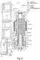
- a male screw portion 71 is fitted onto the inner peripheral surface of the first housing 76 via a substantially tubular first rotation limiting mechanism 81.
- the male screw portion 71 has a rod-like shape as a whole.
- the male screw portion 71 includes a screw body 71A and a rod 71F.
- the screw body 71A is positioned on the I side in the vehicle width direction relative to the rod 71F.
- the screw body 71A includes a body portion 71B and a shaft portion 71D.
- the body portion 71B is positioned on the H side in the vehicle width direction relative to the shaft portion 71D.
- the entire outer peripheral surface of the body portion 71B is externally threaded.
- the body portion 71B has a fixing hole 71C formed therein, which is open through the H-side end surface of the body portion 71B in the vehicle width direction.
- the fixing hole 71C extends from the H-side end surface of the body portion 71B in the vehicle width direction toward the I side in the vehicle width direction.
- the fixing hole 71C is positioned at the center of the H-side end surface of the body portion 71B in the vehicle width direction.
- the fixing hole 71C has a polygonal cross-sectional shape when cut in the direction orthogonal to the vehicle width direction.
- the shaft portion 71D extends from the I-side end surface of the body portion 71B in the vehicle width direction toward the I side in the vehicle width direction.
- the shaft portion 71D is inserted into the first rotation limiting mechanism 81.
- the shaft portion 71D extends through the first rotation limiting mechanism 81 to be also inserted into the through hole 76A formed in the first housing 76.
- the I-side end portion of the shaft portion 71D in the vehicle width direction constitutes a first adjusting portion 71E substantially shaped like a hexagonal cylinder.
- the rod 71F shaped like a column extending in the vehicle width direction.
- the rod 71F has a polygonal cross-sectional shape when cut in the direction orthogonal to the vehicle width direction, which is substantially the same as the cross-sectional shape of the fixing hole 71C obtained when cutting the fixing hole 71C in the direction orthogonal to the vehicle width direction.
- the outer peripheral surface of the rod 71F is fixedly attached onto the inner peripheral surface of the fixing hole 71C formed in the screw body 71A.
- the central axis of the rod 71F is aligned with the central axis of the screw body 71A.
- the H-side end portion of the rod 71F in the vehicle width direction protrudes beyond the fixing hole 71C formed in the screw body 71A.
- the H-side end portion of the rod 71F in the vehicle width direction constitutes a second adjusting portion 71G substantially shaped like a hexagonal cylinder.
- the second adjusting portion 71G is positioned on the H-side end portion of the rod 71F in the vehicle width direction, which is positioned opposite to the end portion of the rod 71F facing the screw body 71A.
- the first adjusting portion 71E mentioned earlier is positioned on the I-side end portion of the screw body 71A in the vehicle width direction, which is positioned opposite to the end portion of the screw body 71A facing the rod 71F.
- the respective end portions of the male screw portion 71 are provided with an adjusting portion.
- the first rotation limiting mechanism 81 limits the rotation of the male screw portion 71 relative to the first housing 76 if torque less than a predetermined value is applied to the male screw portion 71. If torque of the predetermined value or greater is applied to the male screw portion 71, on the other hand, the first rotation limiting mechanism 81 allows the rotation of the male screw portion 71 relative to the first housing 76.
- the gap adjusting mechanism 70 has a second housing 77 coupled with the rotating arm 40A, which is the H-side one of the rotating arms 40 in the vehicle width direction.
- the second housing 77 has a bottom and a tubular shape and is open on the I side in the vehicle width direction.
- the second housing 77 has a through hole 77A formed therein.
- the through hole 77A penetrates the bottom wall of the second housing 77.
- the second housing 77 is coupled with the rotating arm 40A such that it is rotatable relative to the rotating arm 40A about an axis extending orthogonally to the central axis of the second housing 77.
- the second housing 77 has a space 77C shaped like a circular cylinder as a whole defined therein. Specifically, the space 77C in the second housing 77 can be roughly divided into a bottom space 77D, an intermediate space 77E, and an end space 77F, which are arranged in the stated order in the vehicle width direction from the H side.
- the bottom space 77D is substantially shaped like a circular cylinder.
- the bottom space 77D is defined by the circumferential wall of the second housing 77, which has a window portion 77B radially penetrating it.
- the window portion 77B is positioned on the K side in the vehicle front-rear direction.
- the bottom space 77D is connected at the I-side end thereof in the vehicle width direction to the intermediate space 77E.
- the size of the intermediate space 77E in the radial direction of the space 77C is less than the size of the bottom space 77D in the radial direction of the space 77C.
- the inner diameter of the intermediate space 77E is less than the inner diameter of the bottom space 77D.
- the intermediate space 77E is connected at the I-side end thereof in the vehicle width direction to the end space 77F.
- the size of the end space 77F in the radial direction of the space 77C is greater than the size of the intermediate space 77E in the radial direction of the space 77C.
- the inner diameter of the end space 77F is greater than the inner diameter of the intermediate space 77E. Accordingly, an annular step surface is formed to demarcate the boundary between the end space 77F and the intermediate space 77E and constitutes a contact target surface 77G.
- the intermediate space 77E is referred to as a first accommodating space.
- the end space 77F is referred to as a second accommodating space.
- the second housing 77 is referred to as a holder member.
- a female screw portion 72 is attached via a one-way clutch 75 substantially shaped like a circular cylinder.
- the female screw portion 72 extends in the vehicle width direction and shaped like a circular cylinder as a whole.
- the female screw portion 72 includes a female screw body 72A, a protrusion 72B, and a connecting tube 72D.
- the connecting tube 72D is positioned on the H side in the vehicle width direction with respect to the female screw body 72A.
- the outer diameter of the connecting tube 72D is substantially equal to the inner diameter of the one-way clutch 75.
- the connecting tube 72D is inserted into the one-way clutch 75, and the outer peripheral surface of the connecting tube 72D is fitted with the one-way clutch 75.
- the connecting tube 72D protrudes toward the H side in the vehicle width direction beyond the one-way clutch 75, and the H-side end surface of the connecting tube 72D in the vehicle width direction contacts the bottom wall of the bottom space 77D within the second housing 77.
- the female screw body 72A extends from the I-side end surface of the connecting tube 72D in the vehicle width direction toward the I side in the vehicle width direction.
- the female screw body 72A is substantially shaped like a circular cylinder.
- the female screw body 72A is internally threaded on the inner peripheral surface thereof in an I-side portion in the vehicle width direction.
- the female screw body 72A is provided in the end space 77F within the second housing 77.
- An I-side portion of the female screw body 72A in the vehicle width direction is on the I side in the vehicle width direction with respect to the second housing 77.
- the protrusion 72B protrudes radially outward from the outer peripheral surface of the H-side end portion of the female screw body 72A on the H side in the vehicle width direction.
- the protrusion 72B extends on the female screw body 72A in the circumferential direction along the entire length and has an annular shape as a whole.
- the radial size of the protrusion 72B is greater than the radial size of the intermediate space 77E and substantially equal to the radial size of the end space 77F.
- the H-side end surface of the protrusion 72B of the female screw portion 72 in the vehicle width direction faces and abuts the contact target surface 77G of the second housing 77 in the vehicle width direction. This means that the H-side end surface of the protrusion 72B of the female screw portion 72 in the vehicle width direction constitutes a contact surface 72C.
- a second rotation limiting mechanism 82 is provided between the outer peripheral surface of the female screw body 72A of the female screw portion 72 and the inner peripheral surface of the end space 77F within the second housing 77.
- the second rotation limiting mechanism 82 includes a stationary portion 82A and a spring 82B.
- the stationary portion 82A is positioned in the end space 77F at the I-side end thereof in the vehicle width direction.
- the stationary portion 82A has an annular shape as a whole.
- the outer peripheral surface of the stationary portion 82A is fixedly attached onto the inner peripheral surface of the end space 77F.
- the spring 82B is positioned between the stationary portion 82A and the protrusion 72B of the female screw portion 72.
- the spring 82B extends from the stationary portion 82A and urges the protrusion 72B of the female screw portion 72 toward the H side in the vehicle width direction. In this way, the spring 82B urges the protrusion 72B of the female screw portion 72 such that the contact surface 72C of the protrusion 72B of the female screw portion 72 can contact the contact target surface 77G of the second housing 77.
- the spring 82B is an example elastic member.
- the second rotation limiting mechanism 82 is configured such that the spring 82B urges the protrusion 72B of the female screw portion 72, thereby generating a force of a predetermined value or greater to tightly press the contact surface 72C of the female screw portion 72 against the contact target surface 77G of the second housing 77. This creates a frictional force between the contact surface 72C and the contact target surface 77G. This frictional force prevents the female screw portion 72 from rotating relative to the second housing 77 if low torque is applied to the female screw portion 72. Specifically, if torque less than a predetermined value is applied to the female screw portion 72, the second rotation limiting mechanism 82 prevents the rotation of the female screw portion 72 relative to the second housing 77.
- the second rotation limiting mechanism 82 allows the rotation of the female screw portion 72 relative to the second housing 77.
- the predetermined value defined for the torque to determine whether to allow the relative rotation of the male and female screw portions 71 and 72 is smaller for the second rotation limiting mechanism 72 than for the first rotation limiting mechanism 81.
- the male screw portion 71 described above is inserted into the female screw portion 72.
- the internal threads of the female screw body 72A of the female screw portion 72 are fitted with the external threads of the body portion 71B of the male screw portion 71.
- the male screw portion 71 extends through the female screw portion 72.
- the rod 71F of the male screw portion 71 is also inserted into the through hole 77A in the second housing 77. This means that the first and second housings 76 and 77 of the gap adjusting mechanism 70 are coupled together via the male and female screw portions 71 and 72.
- a cylindrical cover 78 is fixedly attached on the outer peripheral surface of the second housing 77.
- the cover 78 extends toward the first housing 76 and is fixedly attached onto the outer peripheral surface of the first housing 76.
- the cover 78 is attached to cover the gap between the second housing 77 and the first housing 76 from radially outside.
- the cover 78 is formed like a bellows in the axial direction so that it is expandable and retractable in the axial direction.
- the first adjusting portion 71E of the male screw portion 71 is exposed through the through hole 76A in the first housing 76 toward the I side in the vehicle width direction.
- the second adjusting portion 71G of the male screw portion 71 is exposed through the through hole 77A in the second housing 77 toward the H side in the vehicle width direction.
- the gap adjusting mechanism 70 is configured such that, if torque of a predetermined value or greater is applied to the male screw portion 71 via the first or second adjusting portion 71E or 71G of the male screw portion 71 using, for example, fingers or mechanical tools, the male screw portion 71 rotates relative to the first and second housings 76 and 77 and the female screw portion 72.
- the male screw portion 71 moves relative to the female screw portion 72 in the axial direction toward a side determined by the rotating direction.
- This changes the length of the gap adjusting mechanism 70 in the axial direction, thereby changing the distance between the base end portions of the rotating arms 40.
- the gap adjusting mechanism 70 can be manually adjusted.
- an input member 73 is attached via a substantially cylindrical one-way clutch 74 on the outer peripheral surface of the connecting tube 72D of the female screw portion 72.
- the input member 73 is shaped like a circular cylinder, and its inner peripheral surface is attached onto the outer peripheral surface of the one-way clutch 74.
- the input member 73 and the one-way clutch 74 are positioned on the H side in the vehicle width direction with respect to the one-way clutch 75 and provided on the H-side end portion of the connecting tube 72D of the female screw portion 72 in the vehicle width direction.
- the outer surface of the input member 73 is partially exposed through the window portion 77B toward the K side in the vehicle front-rear direction.
- the one-way clutch 74 prevents the input member 73 from rotating in one direction relative to the female screw portion 72 and allows the input member 73 to rotate in the other direction relative to the female screw portion 72. Accordingly, if the input member 73 rotates in the one direction, the female screw portion 72 follows the input member 73 and thus rotates in the one direction.
- the one-way clutch 75 allows the female screw portion 72 to rotate in the one direction relative to the second housing 77 and prevents the female screw portion 72 from rotating in the other direction relative to the second housing 77. Accordingly, if the female screw portion 72 rotates in the one direction together with the input member 73, the female screw portion 72 rotates in the one direction relative to the second housing 77.
- the one-way clutch 75 corresponds to a one-way clutch for allowing a first one of screw portions to rotate relative to a second one of the screw portions in one direction and preventing the first one of the screw portions from rotating relative to the second one of the screw portions in the other direction.
- the female screw portion 72 corresponds to the first one of the screw portions
- the male screw portion 71 corresponds to the second one of the screw portions.
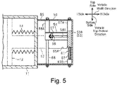
- a converting portion 50 for receiving and converting the linear movement made by the output shaft 13 into movement in the vehicle top-bottom direction is provided on the H side in the vehicle width direction with respect to the first cylinder 11.
- the converting portion 50 transmits the movement in the vehicle top-bottom direction to the gap adjusting mechanism 70.
- the converting portion 50 includes a case 65 enclosing the tip end portion of the output shaft 13.
- the case 65 is open toward the I side in the vehicle width direction and shaped like a quadrangular box as a whole.
- the tip end portion of the output shaft 13 reaches the internal space within the case 65.
- the J-side wall portion of the case 65 in the vehicle front-rear direction has an opening 65A formed therein, and the opening 65A penetrates the wall portion in the vehicle front-rear direction.
- the case 65 has a rod-shaped first shaft portion 66 fixedly attached therein, and the first shaft portion 66 extends in the vehicle top-bottom direction. When seen in the vehicle width direction, the first shaft portion 66 is positioned to overlap the output shaft 13. As shown in Fig. 2 , the first shaft portion 66 is positioned in the vicinity of the H-side wall portion of the case 65 in the vehicle width direction. As shown in Fig. 3 , the top-side end portion of the first shaft portion 66 has a first stopper 66A fixedly attached thereto, which is configured to serve as a registration member.
- the case 65 has a rod-shaped second shaft portion 67 fixedly attached therein, and the second shaft portion 67 extends in the vehicle top-bottom direction.
- the second shaft portion 67 is positioned in the vicinity of the H-side wall portion of the case 65 in the vehicle width direction.
- the second shaft portion 67 is positioned on the J side in the vehicle front-rear direction with respect to the first shaft portion 66 and in the vicinity of the J-side wall portion of the case 65 in the vehicle front-rear direction.
- the top-side end portion of the second shaft portion 67 has a second top-side stopper 67A fixedly attached thereto, which is configured to serve as a registration member.
- the bottom-side end portion of the second shaft portion 67 has a second bottom-side stopper 67B fixedly attached thereto, which is configured to serve as a registration member.
- the case 65 has a rod-shaped third shaft portion 68 fixedly attached therein, and the third shaft portion 68 extends in the vehicle top-bottom direction.
- the third shaft portion 68 is positioned in the vicinity of the J-side wall portion of the case 65 in the vehicle front-rear direction.
- the third shaft portion 68 is positioned on the I side in the vehicle width direction with respect to the second shaft portion 67 and in the vicinity of the end wall 11C of the first cylinder 11, which is on the H side in the vehicle width direction.
- the top-side end portion of the third shaft portion 68 has a third stopper 68A fixedly attached thereto, which is configured to serve as a registration member.
- the first, second and third shaft portions 66, 67 and 68 support a movable member 52, which is movable in the vehicle top-bottom direction relative to the gap adjusting mechanism 70.
- the movable member 52 includes a first movable member 53 and a second movable member 54.
- the first movable member 53 is supported on the first and second shaft portions 66 and 67.
- the first movable member 53 is movable in the vehicle top-bottom direction relative to the first and second shaft portions 66 and 67.
- a body portion 53A of the first movable member 53 is positioned between the first shaft portion 66 and the second shaft portion 67.
- the body portion 53A is shaped like a rectangular plate and extends in the vehicle top-bottom direction.
- An input portion 53B extends from the bottom-side end portion of the body portion 53A toward the K side in the vehicle front-rear direction.
- the input portion 53B has a through hole provided therein, which is not shown, and the first shaft portion 66 is inserted through the through hole.
- An output portion 53C extends from the top-side end portion of the body portion 53A toward the J side in the vehicle front-rear direction.
- the output portion 53C has a through hole provided therein, which is not shown, and the second shaft portion 67 is inserted through the through hole.
- the second movable member 54 is fixedly attached to the lower side of the output portion 53C of the first movable member 53.
- the second movable member 54 extends toward the I side in the vehicle width direction and is substantially shaped like a rectangular plate.
- the H-side end portion of the second movable member 54 in the vehicle width direction has a through hole provided therein, which is not shown, and the second shaft portion 67 is inserted through the through hole.
- the I-side end portion of the second movable member 54 in the vehicle width direction has a through hole provided therein, which is not shown, and the third shaft portion 68 is inserted through the through hole.
- the second movable member 54 is thus supported on the second and third shaft portions 67 and 68 and movable in the vehicle top-bottom direction together with the first movable member 53.
- the second movable member 54 has a groove portion 54A extending therethrough in the vehicle front-rear direction.
- the groove portion 54A extends from the H-side end of the second movable member 54 in the vehicle width direction to the vicinity of the I-side end of the second movable member 54 in the vehicle width direction. Accordingly, the groove portion 54A is a slot having a larger size in the vehicle width direction than in the vehicle top-bottom direction.
- the first shaft portion 66 has a retaining portion 63 supported thereon, which is movable in the vehicle top-bottom direction.
- the retaining portion 63 is substantially U shaped and open toward the H side in the vehicle width direction, and the respective ends of the U-shaped retaining portion 63 are supported on the first shaft portion 66.
- a first one of the ends of the U-shaped retaining portion 63 is supported on the first shaft portion 66 while being positioned above the input portion 53B of the first movable member 53 and below the first stopper 66A.
- a second one of the ends of the U-shaped retaining portion 63 is supported on the first shaft portion 66 while being positioned below the input portion 53B of the first movable member 53.
- an absorption spring 62 is provided to urge the first movable member 53 in the vehicle top-bottom direction.
- the absorption spring 62 is supported on the first shaft portion 66 while being elastically compressed between the first end of the U-shaped retaining portion 63 and the input portion 53B of the first movable member 53 and urges the input portion 53B of the first movable member 53 downward in the vehicle top-bottom direction from the first end of the retaining portion 63.
- the maximum elastic deformation of the absorption spring 62 in the vehicle top-bottom direction is greater than the maximum movement of the movable member 52 in the vehicle top-bottom direction.
- the maximum movement of the movable member 52 denotes the movable range in the vehicle top-bottom direction within which the movable member 52, which is supported on the first, second and third shaft portions 66, 67 and 68, can move.
- a transmitting portion 51 is fixedly attached to the I-side portion of the retaining portion 63 in the vehicle width direction, and the transmitting portion 51 receives and converts the force from the output shaft 13 and into a force acting in the vehicle top-bottom direction.
- the transmitting portion 51 is substantially shaped like a triangular prism such that it is upwardly tapered in the vehicle top-bottom direction.
- the transmitting portion 51 when seen in the vehicle front-rear direction, the transmitting portion 51 is shaped like a right-angled triangle and an inclined surface 51A of the transmitting portion 51 faces the output shaft 13, and an acute angle X formed between the central axis line of the output shaft 13 and the inclined surface 51A of the transmitting portion 51 is approximately 70 degrees. In other words, the acute angle formed between the linear movement direction of the output shaft 13 and the inclined surface 51A of the transmitting portion 51 is greater than 45 degrees.
- the inclined surface 51A of the transmitting portion 51 is a flat surface.
- the second shaft portion 67 has a return spring 61 supported thereon, which is configured to urge the second movable member 54 in the vehicle top-bottom direction.
- the return spring 61 is elastically compressed between the bottom-side end of the second movable member 54 and the second bottom-side stopper 67B to extend from the second bottom-side stopper 67B to urge the second movable member 54 upward.
- the bottom-side portion of the absorption spring 62 overlaps the top-side portion of the return spring 61.
- the absorption spring 62 and return spring 61 both touch the movable member 52 and are coupled together via the movable member 52.
- the absorption spring 62 and return spring 61 are coupled together via the movable member 52 while being arranged in parallel and partly overlap each other in the vehicle top-bottom direction.
- the second movable member 54 is coupled to a coupling portion 55 configured to transmit a force to the gap adjusting mechanism 70 as the movable member 52 moves.
- the coupling portion 55 includes a rod member 56 substantially shaped like a quadrangular prism, which is inserted into the groove portion 54A in the second movable member 54.
- the size of the rod member 56 in the vehicle top-bottom direction is substantially equal to the size of the groove portion 54A in the vehicle top-bottom direction.
- the rod member 56 is incapable of moving relative to the second movable member 54 in the vehicle top-bottom direction and thus moves in the vehicle top-bottom direction together with the second movable member 54 as the second movable member 54 moves in the vehicle top-bottom direction.
- the size of the rod member 56 in the vehicle width direction is less than the size of the groove portion 54A in the vehicle width direction.
- the rod member 56 is movable relative to the second movable member 54 in the vehicle width direction.
- the rod member 56 is inserted into the grove portion 54A extending in the vehicle front-rear direction, so that the rod member 56 is movable relative to the second movable member 54 in the vehicle front-rear direction.
- the K-side end of the rod member 56 in the vehicle front-rear direction has a limiting pin 57 fixedly attached thereto, which extends in the vehicle top-bottom direction.
- the size of the limiting pin 57 in the vehicle top-bottom direction is greater than the size of the groove portion 54A in the vehicle top-bottom direction, so that the limiting pin 57 prevents the rod member 56 from slipping out of the groove portion 54A.
- the J-side end of the rod member 56 in the vehicle front-rear direction has a supporting portion 58 fixedly attached thereto, which is coupled to the input member 73 of the gap adjusting mechanism 70.
- the supporting portion 58 is supported on the second housing 77 of the gap adjusting mechanism 70 via a guide plate 59 fixedly attached onto the second housing 77 of the gap adjusting mechanism 70.
- the guide plate 59 is shaped like a quadrangular plate as a whole and has an elongated hole 59A formed therein, which is a through hole and long in the vehicle top-bottom direction.
- the supporting portion 58 is inserted into the elongated hole 59A in the guide plate 59, so that the guide plate 59 supports the supporting portion 58 in a movable manner in the vehicle top-bottom direction. Accordingly, as the rod member 56 moves in the vehicle top-bottom direction, the supporting portion 58 moves in the vehicle top-bottom direction together with the rod member 56. As the supporting portion 58 moves in the vehicle top-bottom direction, a force acting in the vehicle top-bottom direction is transmitted to the input member 73 of the gap adjusting mechanism 70.
- the supporting portion 58 rotatably supports the rod member 56 via a supporting pin 58A extending in the vehicle top-bottom direction. Accordingly, the rod member 56 is rotatable about the coupling portion between the J-side end of the rod member 56 in the vehicle front-rear direction and the supporting pin 58A.
- the brake device 10 operates. While the railroad vehicle is in motion, the compressed air is introduced into the space 21E of the internal space within the second cylinder 21, which is positioned on the H side in the vehicle width direction relative to the second piston 22. With the compressed air introduced into the space 21E in this way, the second piston 22 and drive shaft 23 overcome the urging force applied by the second spring 24 and move toward the I side in the vehicle width direction, so that the driving force applied by the drive shaft 23 resulting from the urging force produced by the second spring 24 is not transmitted to the output shaft 13. Accordingly, assuming that the driving force from the drive shaft 23 is not transmitted to the output shaft 13, the following describes how the brake device 10 operates.
- the first piston 12 and output shaft 13 overcome the urging force produced by the first spring 14 and linearly move toward the H side in the vehicle width direction, as shown in Fig. 2 .
- the I-side portion of the inner peripheral surface of the insertion hole 13A in the output shaft 13 in the vehicle width direction touches the roller 33 of the rotating lever 30.
- the roller 33 of the rotating lever 30 then moves toward the H side in the vehicle width direction while the roller 33 remains touching the I-side portion of the inner peripheral surface of the insertion hole 13A in the output shaft 13 in the vehicle width direction but the touching portion of the roller 33 gradually changes.
- the rotating lever 30 rotates about the rotation center P1 in one direction, or clockwise as viewed in Fig. 2 .
- the coupling portion between the rotating arm 40A which is positioned on the H side in the vehicle width direction, and the rotating lever 30 also rotates about the rotation center P1 clockwise.
- the rotating arm 40A receives a force directed toward the I side in the vehicle width direction at the coupling portion between the rotating arm 40A and the rotating lever 30.
- the rotating arm 40A moves toward the I side in the vehicle width direction.
- the gap adjusting mechanism 70 also moves toward the I side in the vehicle width direction.
- the coupling portion between the base end portion of the rotating arm 40B and the gap adjusting mechanism 70 moves toward the I side in the vehicle width direction.
- the rotating arm 40B is rotatably coupled with the caliper body 86A. Therefore, the rotating arm 40B rotates counterclockwise about the coupling portion between the rotating arm 40B and the caliper body 86A.
- the urging force produced by the first spring 14 causes the first piston 12 and the output shaft 13 to linearly move toward the I side in the vehicle width direction.
- the H-side portion of the inner peripheral surface of the insertion hole 13A in the output shaft 13 in the vehicle width direction then touches the roller 33 of the rotating lever 30.
- the roller 33 of the rotating lever 30 then moves toward the I side in the vehicle width direction while the roller 33 remains touching the H-side portion of the inner peripheral surface of the insertion hole 13A in the output shaft 13 in the vehicle width direction but the touching portion of the roller 33 gradually changes.
- the rotating lever 30 rotates about the rotation center P1 in the other direction, or counterclockwise as viewed in Fig. 2 .
- the coupling portion between the rotating arm 40A and the rotating lever 30 also rotates counterclockwise about the rotation center P1.
- the rotating arm 40A receives a force directed toward the H side in the vehicle width direction at the coupling portion between the rotating arm 40A and the rotating lever 30.
- the rotating arm 40A moves toward the H side in the vehicle width direction.
- the gap adjusting mechanism 70 also moves toward the H side in the vehicle width direction.
- the coupling portion between the base end portion of the rotating arm 40B and the gap adjusting mechanism 70 moves toward the H side in the vehicle width direction. Therefore, the rotating arm 40B rotates clockwise about the coupling portion between the rotating arm 40B and the caliper body 86A. This in turn moves the attaching portion 45 and the brake pad 90 coupled with the rotating arm 40B away from the disc 95, so that the brake pad 90 on the rotating arm 40B separates from the end surface of the disc 95.
- the friction between the rotating disc 95 and the brake pad 90 gradually wears the brake pad 90 off.
- the distance between the brake pad 90 and the disc 95 observed when the output shaft 13 is positioned the furthest on the I side in the vehicle width direction increases. This in turn increases the distance by which the output shaft 13 needs to linearly move in order to bring the brake pad 90, which is positioned away from the disc 95, into contact with the disc 95. If the output shaft 13 moves by a predetermined value or more, the rotational body 13B provided on the output shaft 13 touches the inclined surface 51A of the transmitting portion 51 as shown in Fig. 4 .
- the transmitting portion 51 moves downward in the vehicle top-bottom direction while the transmitting portion 51 remains touching the rotational body 13B on the output shaft 13 but the touching portion of the transmitting portion 51 gradually changes.
- the force acting in the direction of the linear movement made by the output shaft 13 is converted into a force acting in the vehicle top-bottom direction. If such a downward force in the vehicle top-bottom direction is transmitted to the first movable member 53 of the movable member 52 via the retaining portion 63 and absorption spring 62, the first and second movable members 53 and 54 move downward in the vehicle top-bottom direction.
- the rod member 56 of the coupling portion 55 which is inserted in the groove portion 54A in the second movable member 54, moves downward in the vehicle top-bottom direction together with the second movable member 54.
- the supporting portion 58 also moves downward in the vehicle top-bottom direction.
- the downward force in the vehicle top-bottom direction is transmitted to the input member 73 of the gap adjusting mechanism 70.
- This causes the input member 73 to rotate in one direction, in other words, counterclockwise in Fig. 3 .
- a force is transmitted from the input member 73 via the one-way clutch 74 to the female screw portion 72, so that the female screw portion 72 rotates counterclockwise together with the input member 73.
- the rotating arm 40A rotates in one direction in the circumferential direction about the rotation center P2 of the rotating arm 40A, in other words, clockwise in Fig. 2 .
- the rotating arm 40B rotates in the other direction in the circumferential direction about the coupling portion between the rotating arm 40B and the caliper body 86A, in other words, counterclockwise in Fig. 2 .
- the rotating arms 40 rotate in this way, the distance between the tip end portions of the rotating arms 40 can be adjusted such that the distance becomes short.
- the output shaft 13 attempts to move toward the I side in the vehicle width direction such that the rotational body 13B on the output shaft 13 moves away from the inclined surface 51A of the transmitting portion 51, the urging force produced by the return spring 61 moves the first and second movable members 53 and 54 of the movable member 52 upward in the vehicle top-bottom direction.
- the rod member 56 of the coupling portion 55 which is inserted in the groove portion 54A in the second movable member 54, moves upward in the vehicle top-bottom direction together with the second movable member 54.
- the supporting portion 58 also moves upward in the vehicle top-bottom direction.
- the upward force in the vehicle top-bottom direction is transmitted to the input member 73 of the gap adjusting mechanism 70.
- This causes the input member 73 to rotate in the other direction, in other words, clockwise in Fig. 3 .
- the input member 73 attempts to rotate clockwise, no force is transmitted from the input member 73 via the one-way clutch 74 to the female screw portion 72, as a result of which the female screw portion 72 is prevented from rotating clockwise.
- the upward force in the vehicle top-bottom direction is transmitted to the transmitting portion 51 via the retaining portion 63 and absorption spring 62, so that the transmitting portion 51 moves upward to go back to the original position.
- the gap adjusting mechanism 70 can be coupled to the pair of rotating arms 40 at different positions.
- the first housing 76 of the gap adjusting mechanism 70 can be alternatively coupled to a portion of the rotating arm 40B that is positioned between (i) the base end portion and (ii) the coupling portion between the rotating arm 40B and the caliper body 86A.
- the second housing 77 of the gap adjusting mechanism 70 can be coupled to the rotating arm 40A at different positions.
- the above embodiment may be practiced without the spring 82B. With such a design, a frictional force can be also produced between the contact surface 72C of the protrusion 72B of the female screw portion 72 and the contact target surface 77G of the second housing 77 as long as they touch each other.
- the above embodiment can be modified such that the contact target surface of the second housing 77 can be differently positioned.
- the I-side end surface of the second housing 77 in the vehicle width direction may constitute the contact target surface.
- the protrusion of the female screw portion 72 can be modified.
- the protrusion 72B may extend in the circumferential direction partially over the female screw body 72A.
- the above embodiment may be practiced without the protrusion of the female screw portion 72.
- the one-way clutch 75 can still prevent the female screw portion 72 from rotating in the other direction relative to the male screw portion 71.
- the male screw portion 71 includes two parts, or the screw body 71A and the rod 71F.
- the embodiment is not limited to such and the male screw portion 71 may be formed as a one-piece member.
- the number of the adjusting portions of the male screw portion 71 can be changed. More specifically, the male screw portion 71 does not need to include the first and second adjusting portions 71E and 71G, but one of the first and second adjusting portions 71E and 71G may be omitted. Alternatively, neither of the first and second adjusting portions 71E and 71G of the male screw portion 71 may be formed. When this design is employed, the gap adjusting mechanism 70 is partly taken into pieces in order to reposition the male and female screw portions 71 and 72, for example.
- the above embodiment can be modified such that the one-way clutch 75 may be positioned differently.
- the one-way clutch 75 may be interposed between the second housing 77 and the male screw portion 71.
- This alternative design is specifically described. Of the male screw portion 71 inserted through the female screw portion 72, a portion protrudes beyond the female screw portion 72. If the one-way clutch 75 is attached to this portion of the male screw portion 71, the one-way clutch 75 can be interposed between the male screw portion 71 and the second housing 77.
- the one-way clutch 75 can be positioned at any different positions as long as, for example, it can prevent the rotation of the female screw portion 72 in the other direction relative to the male screw portion 71.
Landscapes
- Engineering & Computer Science (AREA)
- General Engineering & Computer Science (AREA)
- Mechanical Engineering (AREA)
- Transportation (AREA)
- Braking Arrangements (AREA)
Applications Claiming Priority (1)
| Application Number | Priority Date | Filing Date | Title |
|---|---|---|---|
| JP2020091658A JP7469141B2 (ja) | 2020-05-26 | 2020-05-26 | ブレーキ装置及びブレーキ装置用の隙間調整機構 |
Publications (2)
| Publication Number | Publication Date |
|---|---|
| EP3916261A1 true EP3916261A1 (de) | 2021-12-01 |
| EP3916261B1 EP3916261B1 (de) | 2022-12-28 |
Family
ID=75659865
Family Applications (1)
| Application Number | Title | Priority Date | Filing Date |
|---|---|---|---|
| EP21170072.9A Active EP3916261B1 (de) | 2020-05-26 | 2021-04-23 | Bremsvorrichtung und spaltverstellmechanismus für eine bremsvorrichtung |
Country Status (3)
| Country | Link |
|---|---|
| EP (1) | EP3916261B1 (de) |
| JP (1) | JP7469141B2 (de) |
| CN (1) | CN113719563B (de) |
Cited By (1)
| Publication number | Priority date | Publication date | Assignee | Title |
|---|---|---|---|---|
| WO2024028055A1 (de) * | 2022-08-03 | 2024-02-08 | Knorr-Bremse Systeme für Schienenfahrzeuge GmbH | Nachstellermodul für eine bremszange einer fahrzeugbremse, fahrzeugbremse mit einem solchen nachstellermodul und verfahren zum notlösen des nachstellermoduls |
Citations (3)
| Publication number | Priority date | Publication date | Assignee | Title |
|---|---|---|---|---|
| US6112861A (en) * | 1997-07-23 | 2000-09-05 | Nippon Ican Ltd. | Disc brake device |
| WO2011095423A1 (de) | 2010-02-02 | 2011-08-11 | Knorr-Bremse Systeme für Schienenfahrzeuge GmbH | Druckstangensteller für kompakt-bremszangeneinheiten mit sich direkt am stellergehäuse abstützenden verschraubungsteil |
| US20180058527A1 (en) * | 2015-03-11 | 2018-03-01 | Kyb Corporation | Brake device |
Family Cites Families (14)
| Publication number | Priority date | Publication date | Assignee | Title |
|---|---|---|---|---|
| FR1454433A (fr) * | 1965-07-12 | 1966-02-11 | Dba Sa | Dispositif de commande à rattrapage d'usure automatique pour frein à disque |
| CH489386A (de) * | 1969-03-17 | 1970-04-30 | Bromsregulator Svenska Ab | Bremsaggregat an einem Schienenfahrzeug |
| GB1448978A (en) * | 1972-12-22 | 1976-09-08 | Girling Ltd | Disc brake assemblies for vehicles |
| US3995722A (en) * | 1975-02-18 | 1976-12-07 | Abex Corporation | Fail-safe disc brake having a slack adjuster mechanism |
| DE3405027A1 (de) * | 1984-02-13 | 1985-08-14 | Alfred Teves Gmbh, 6000 Frankfurt | Betaetigungsvorrichtung fuer eine reibungsbremse |
| DE4017950A1 (de) * | 1990-06-05 | 1991-12-12 | Wabco Westinghouse Fahrzeug | Bremsbetaetigungseinrichtung mit einer einrichtung zum nachstellen einer bremse |
| JP2667631B2 (ja) * | 1994-02-18 | 1997-10-27 | 日本アイキャン株式会社 | ディスクブレーキ装置 |
| JP4809282B2 (ja) * | 2007-04-12 | 2011-11-09 | ナブテスコ株式会社 | ブレーキシリンダ装置及びブレーキキャリパ装置 |
| CN102753853B (zh) | 2010-02-02 | 2015-05-13 | 克诺尔-布里姆斯轨道车辆系统有限公司 | 包括能挡靠到弹性止挡上的调节杆的用于紧凑型制动钳单元的压杆调节器 |
| CN102384191A (zh) * | 2011-07-06 | 2012-03-21 | 隆中控股集团有限公司 | 一种汽车盘式制动器中间隙自调机构的调整器 |
| CN202349048U (zh) * | 2011-12-09 | 2012-07-25 | 浙江大学台州研究院 | 具有间隙调节功能的车用电子机械制动器 |
| JP5880003B2 (ja) * | 2011-12-14 | 2016-03-08 | 新日鐵住金株式会社 | 鉄道車両用キャリパブレーキ装置 |
| JP6376883B2 (ja) * | 2014-07-31 | 2018-08-22 | 日立オートモティブシステムズ株式会社 | ディスクブレーキ |
| JP6543149B2 (ja) * | 2015-09-25 | 2019-07-10 | Kyb株式会社 | ブレーキ装置 |
-
2020
- 2020-05-26 JP JP2020091658A patent/JP7469141B2/ja active Active
-
2021
- 2021-04-23 EP EP21170072.9A patent/EP3916261B1/de active Active
- 2021-04-26 CN CN202110464359.4A patent/CN113719563B/zh active Active
Patent Citations (3)
| Publication number | Priority date | Publication date | Assignee | Title |
|---|---|---|---|---|
| US6112861A (en) * | 1997-07-23 | 2000-09-05 | Nippon Ican Ltd. | Disc brake device |
| WO2011095423A1 (de) | 2010-02-02 | 2011-08-11 | Knorr-Bremse Systeme für Schienenfahrzeuge GmbH | Druckstangensteller für kompakt-bremszangeneinheiten mit sich direkt am stellergehäuse abstützenden verschraubungsteil |
| US20180058527A1 (en) * | 2015-03-11 | 2018-03-01 | Kyb Corporation | Brake device |
Cited By (1)
| Publication number | Priority date | Publication date | Assignee | Title |
|---|---|---|---|---|
| WO2024028055A1 (de) * | 2022-08-03 | 2024-02-08 | Knorr-Bremse Systeme für Schienenfahrzeuge GmbH | Nachstellermodul für eine bremszange einer fahrzeugbremse, fahrzeugbremse mit einem solchen nachstellermodul und verfahren zum notlösen des nachstellermoduls |
Also Published As
| Publication number | Publication date |
|---|---|
| CN113719563A (zh) | 2021-11-30 |
| CN113719563B (zh) | 2023-06-13 |
| JP7469141B2 (ja) | 2024-04-16 |
| EP3916261B1 (de) | 2022-12-28 |
| JP2021188633A (ja) | 2021-12-13 |
Similar Documents
| Publication | Publication Date | Title |
|---|---|---|
| JP6382340B2 (ja) | ドラムブレーキ装置 | |
| US9889865B2 (en) | Brake cylinder device and disc brake device | |
| JP6041746B2 (ja) | ディスクブレーキ用摩擦パッド組立体 | |
| JP4878363B2 (ja) | 車輪ブレーキ | |
| EP3916261B1 (de) | Bremsvorrichtung und spaltverstellmechanismus für eine bremsvorrichtung | |
| CN108026994A (zh) | 制动装置 | |
| WO2014189089A1 (ja) | ディスクブレーキ装置 | |
| EP3916262B1 (de) | Bremsvorrichtung | |
| KR102132510B1 (ko) | 디스크 브레이크 장치 | |
| EP3992055B1 (de) | Bremssattel | |
| JP6117578B2 (ja) | 遠心力を利用したブレーキ装置 | |
| WO2018199114A1 (ja) | ディスクブレーキ装置 | |
| JP5064781B2 (ja) | ディスクブレーキ装置 | |
| JP2008151168A (ja) | ディスクブレーキ装置 | |
| JP5691929B2 (ja) | ブレーキ装置 | |
| EP3822144A1 (de) | Bremsvorrichtung | |
| WO2024162272A1 (ja) | 電動制動装置 | |
| JP2008239120A (ja) | ディスクブレーキ・アーム装置 | |
| JP2010190233A (ja) | ディスクブレーキのブレーキトルクアンカー | |
| JP2008241009A (ja) | ディスクブレーキ装置 | |
| JPH07145835A (ja) | 送りネジにおけるブレーキ機構 |
Legal Events
| Date | Code | Title | Description |
|---|---|---|---|
| PUAI | Public reference made under article 153(3) epc to a published international application that has entered the european phase |
Free format text: ORIGINAL CODE: 0009012 |
|
| STAA | Information on the status of an ep patent application or granted ep patent |
Free format text: STATUS: REQUEST FOR EXAMINATION WAS MADE |
|
| 17P | Request for examination filed |
Effective date: 20210423 |
|
| AK | Designated contracting states |
Kind code of ref document: A1 Designated state(s): AL AT BE BG CH CY CZ DE DK EE ES FI FR GB GR HR HU IE IS IT LI LT LU LV MC MK MT NL NO PL PT RO RS SE SI SK SM TR |
|
| B565 | Issuance of search results under rule 164(2) epc |
Effective date: 20210922 |
|
| GRAP | Despatch of communication of intention to grant a patent |
Free format text: ORIGINAL CODE: EPIDOSNIGR1 |
|
| STAA | Information on the status of an ep patent application or granted ep patent |
Free format text: STATUS: GRANT OF PATENT IS INTENDED |
|
| INTG | Intention to grant announced |
Effective date: 20220912 |
|
| RIN1 | Information on inventor provided before grant (corrected) |
Inventor name: OHNO, TOMOYA |
|
| GRAS | Grant fee paid |
Free format text: ORIGINAL CODE: EPIDOSNIGR3 |
|
| GRAA | (expected) grant |
Free format text: ORIGINAL CODE: 0009210 |
|
| STAA | Information on the status of an ep patent application or granted ep patent |
Free format text: STATUS: THE PATENT HAS BEEN GRANTED |
|
| AK | Designated contracting states |
Kind code of ref document: B1 Designated state(s): AL AT BE BG CH CY CZ DE DK EE ES FI FR GB GR HR HU IE IS IT LI LT LU LV MC MK MT NL NO PL PT RO RS SE SI SK SM TR |
|
| REG | Reference to a national code |
Ref country code: GB Ref legal event code: FG4D |
|
| REG | Reference to a national code |
Ref country code: CH Ref legal event code: EP |
|
| REG | Reference to a national code |
Ref country code: DE Ref legal event code: R096 Ref document number: 602021001078 Country of ref document: DE |
|
| REG | Reference to a national code |
Ref country code: AT Ref legal event code: REF Ref document number: 1540678 Country of ref document: AT Kind code of ref document: T Effective date: 20230115 |
|
| REG | Reference to a national code |
Ref country code: IE Ref legal event code: FG4D |
|
| REG | Reference to a national code |
Ref country code: LT Ref legal event code: MG9D |
|
| PG25 | Lapsed in a contracting state [announced via postgrant information from national office to epo] |
Ref country code: SE Free format text: LAPSE BECAUSE OF FAILURE TO SUBMIT A TRANSLATION OF THE DESCRIPTION OR TO PAY THE FEE WITHIN THE PRESCRIBED TIME-LIMIT Effective date: 20221228 Ref country code: NO Free format text: LAPSE BECAUSE OF FAILURE TO SUBMIT A TRANSLATION OF THE DESCRIPTION OR TO PAY THE FEE WITHIN THE PRESCRIBED TIME-LIMIT Effective date: 20230328 Ref country code: LT Free format text: LAPSE BECAUSE OF FAILURE TO SUBMIT A TRANSLATION OF THE DESCRIPTION OR TO PAY THE FEE WITHIN THE PRESCRIBED TIME-LIMIT Effective date: 20221228 Ref country code: FI Free format text: LAPSE BECAUSE OF FAILURE TO SUBMIT A TRANSLATION OF THE DESCRIPTION OR TO PAY THE FEE WITHIN THE PRESCRIBED TIME-LIMIT Effective date: 20221228 |
|
| REG | Reference to a national code |
Ref country code: NL Ref legal event code: MP Effective date: 20221228 |
|
| REG | Reference to a national code |
Ref country code: AT Ref legal event code: MK05 Ref document number: 1540678 Country of ref document: AT Kind code of ref document: T Effective date: 20221228 |
|
| PG25 | Lapsed in a contracting state [announced via postgrant information from national office to epo] |
Ref country code: RS Free format text: LAPSE BECAUSE OF FAILURE TO SUBMIT A TRANSLATION OF THE DESCRIPTION OR TO PAY THE FEE WITHIN THE PRESCRIBED TIME-LIMIT Effective date: 20221228 Ref country code: LV Free format text: LAPSE BECAUSE OF FAILURE TO SUBMIT A TRANSLATION OF THE DESCRIPTION OR TO PAY THE FEE WITHIN THE PRESCRIBED TIME-LIMIT Effective date: 20221228 Ref country code: HR Free format text: LAPSE BECAUSE OF FAILURE TO SUBMIT A TRANSLATION OF THE DESCRIPTION OR TO PAY THE FEE WITHIN THE PRESCRIBED TIME-LIMIT Effective date: 20221228 Ref country code: GR Free format text: LAPSE BECAUSE OF FAILURE TO SUBMIT A TRANSLATION OF THE DESCRIPTION OR TO PAY THE FEE WITHIN THE PRESCRIBED TIME-LIMIT Effective date: 20230329 |
|
| P01 | Opt-out of the competence of the unified patent court (upc) registered |
Effective date: 20230523 |
|
| PG25 | Lapsed in a contracting state [announced via postgrant information from national office to epo] |
Ref country code: NL Free format text: LAPSE BECAUSE OF FAILURE TO SUBMIT A TRANSLATION OF THE DESCRIPTION OR TO PAY THE FEE WITHIN THE PRESCRIBED TIME-LIMIT Effective date: 20221228 |
|
| PG25 | Lapsed in a contracting state [announced via postgrant information from national office to epo] |
Ref country code: SM Free format text: LAPSE BECAUSE OF FAILURE TO SUBMIT A TRANSLATION OF THE DESCRIPTION OR TO PAY THE FEE WITHIN THE PRESCRIBED TIME-LIMIT Effective date: 20221228 Ref country code: RO Free format text: LAPSE BECAUSE OF FAILURE TO SUBMIT A TRANSLATION OF THE DESCRIPTION OR TO PAY THE FEE WITHIN THE PRESCRIBED TIME-LIMIT Effective date: 20221228 Ref country code: PT Free format text: LAPSE BECAUSE OF FAILURE TO SUBMIT A TRANSLATION OF THE DESCRIPTION OR TO PAY THE FEE WITHIN THE PRESCRIBED TIME-LIMIT Effective date: 20230428 Ref country code: ES Free format text: LAPSE BECAUSE OF FAILURE TO SUBMIT A TRANSLATION OF THE DESCRIPTION OR TO PAY THE FEE WITHIN THE PRESCRIBED TIME-LIMIT Effective date: 20221228 Ref country code: EE Free format text: LAPSE BECAUSE OF FAILURE TO SUBMIT A TRANSLATION OF THE DESCRIPTION OR TO PAY THE FEE WITHIN THE PRESCRIBED TIME-LIMIT Effective date: 20221228 Ref country code: CZ Free format text: LAPSE BECAUSE OF FAILURE TO SUBMIT A TRANSLATION OF THE DESCRIPTION OR TO PAY THE FEE WITHIN THE PRESCRIBED TIME-LIMIT Effective date: 20221228 Ref country code: AT Free format text: LAPSE BECAUSE OF FAILURE TO SUBMIT A TRANSLATION OF THE DESCRIPTION OR TO PAY THE FEE WITHIN THE PRESCRIBED TIME-LIMIT Effective date: 20221228 |
|
| PG25 | Lapsed in a contracting state [announced via postgrant information from national office to epo] |
Ref country code: SK Free format text: LAPSE BECAUSE OF FAILURE TO SUBMIT A TRANSLATION OF THE DESCRIPTION OR TO PAY THE FEE WITHIN THE PRESCRIBED TIME-LIMIT Effective date: 20221228 Ref country code: PL Free format text: LAPSE BECAUSE OF FAILURE TO SUBMIT A TRANSLATION OF THE DESCRIPTION OR TO PAY THE FEE WITHIN THE PRESCRIBED TIME-LIMIT Effective date: 20221228 Ref country code: IS Free format text: LAPSE BECAUSE OF FAILURE TO SUBMIT A TRANSLATION OF THE DESCRIPTION OR TO PAY THE FEE WITHIN THE PRESCRIBED TIME-LIMIT Effective date: 20230428 Ref country code: AL Free format text: LAPSE BECAUSE OF FAILURE TO SUBMIT A TRANSLATION OF THE DESCRIPTION OR TO PAY THE FEE WITHIN THE PRESCRIBED TIME-LIMIT Effective date: 20221228 |
|
| REG | Reference to a national code |
Ref country code: DE Ref legal event code: R097 Ref document number: 602021001078 Country of ref document: DE |
|
| PG25 | Lapsed in a contracting state [announced via postgrant information from national office to epo] |
Ref country code: DK Free format text: LAPSE BECAUSE OF FAILURE TO SUBMIT A TRANSLATION OF THE DESCRIPTION OR TO PAY THE FEE WITHIN THE PRESCRIBED TIME-LIMIT Effective date: 20221228 |
|
| PLBE | No opposition filed within time limit |
Free format text: ORIGINAL CODE: 0009261 |
|
| STAA | Information on the status of an ep patent application or granted ep patent |
Free format text: STATUS: NO OPPOSITION FILED WITHIN TIME LIMIT |
|
| 26N | No opposition filed |
Effective date: 20230929 |
|
| PG25 | Lapsed in a contracting state [announced via postgrant information from national office to epo] |
Ref country code: LU Free format text: LAPSE BECAUSE OF NON-PAYMENT OF DUE FEES Effective date: 20230423 |
|
| REG | Reference to a national code |
Ref country code: BE Ref legal event code: MM Effective date: 20230430 |
|
| PG25 | Lapsed in a contracting state [announced via postgrant information from national office to epo] |
Ref country code: MC Free format text: LAPSE BECAUSE OF FAILURE TO SUBMIT A TRANSLATION OF THE DESCRIPTION OR TO PAY THE FEE WITHIN THE PRESCRIBED TIME-LIMIT Effective date: 20221228 |
|
| PG25 | Lapsed in a contracting state [announced via postgrant information from national office to epo] |
Ref country code: SI Free format text: LAPSE BECAUSE OF FAILURE TO SUBMIT A TRANSLATION OF THE DESCRIPTION OR TO PAY THE FEE WITHIN THE PRESCRIBED TIME-LIMIT Effective date: 20221228 Ref country code: MC Free format text: LAPSE BECAUSE OF FAILURE TO SUBMIT A TRANSLATION OF THE DESCRIPTION OR TO PAY THE FEE WITHIN THE PRESCRIBED TIME-LIMIT Effective date: 20221228 |
|
| REG | Reference to a national code |
Ref country code: IE Ref legal event code: MM4A |
|
| PG25 | Lapsed in a contracting state [announced via postgrant information from national office to epo] |
Ref country code: BE Free format text: LAPSE BECAUSE OF NON-PAYMENT OF DUE FEES Effective date: 20230430 |
|
| PG25 | Lapsed in a contracting state [announced via postgrant information from national office to epo] |
Ref country code: IE Free format text: LAPSE BECAUSE OF NON-PAYMENT OF DUE FEES Effective date: 20230423 |
|
| PG25 | Lapsed in a contracting state [announced via postgrant information from national office to epo] |
Ref country code: IE Free format text: LAPSE BECAUSE OF NON-PAYMENT OF DUE FEES Effective date: 20230423 |
|
| PG25 | Lapsed in a contracting state [announced via postgrant information from national office to epo] |
Ref country code: BG Free format text: LAPSE BECAUSE OF FAILURE TO SUBMIT A TRANSLATION OF THE DESCRIPTION OR TO PAY THE FEE WITHIN THE PRESCRIBED TIME-LIMIT Effective date: 20221228 |
|
| PG25 | Lapsed in a contracting state [announced via postgrant information from national office to epo] |
Ref country code: BG Free format text: LAPSE BECAUSE OF FAILURE TO SUBMIT A TRANSLATION OF THE DESCRIPTION OR TO PAY THE FEE WITHIN THE PRESCRIBED TIME-LIMIT Effective date: 20221228 |
|
| REG | Reference to a national code |
Ref country code: CH Ref legal event code: PL |
|
| PG25 | Lapsed in a contracting state [announced via postgrant information from national office to epo] |
Ref country code: CH Free format text: LAPSE BECAUSE OF NON-PAYMENT OF DUE FEES Effective date: 20240430 |
|
| PGFP | Annual fee paid to national office [announced via postgrant information from national office to epo] |
Ref country code: DE Payment date: 20250422 Year of fee payment: 5 |
|
| PGFP | Annual fee paid to national office [announced via postgrant information from national office to epo] |
Ref country code: GB Payment date: 20250423 Year of fee payment: 5 |
|
| PGFP | Annual fee paid to national office [announced via postgrant information from national office to epo] |
Ref country code: IT Payment date: 20250424 Year of fee payment: 5 |
|
| PGFP | Annual fee paid to national office [announced via postgrant information from national office to epo] |
Ref country code: FR Payment date: 20250425 Year of fee payment: 5 |
|
| PG25 | Lapsed in a contracting state [announced via postgrant information from national office to epo] |
Ref country code: CY Free format text: LAPSE BECAUSE OF FAILURE TO SUBMIT A TRANSLATION OF THE DESCRIPTION OR TO PAY THE FEE WITHIN THE PRESCRIBED TIME-LIMIT; INVALID AB INITIO Effective date: 20210423 |
|
| PG25 | Lapsed in a contracting state [announced via postgrant information from national office to epo] |
Ref country code: HU Free format text: LAPSE BECAUSE OF FAILURE TO SUBMIT A TRANSLATION OF THE DESCRIPTION OR TO PAY THE FEE WITHIN THE PRESCRIBED TIME-LIMIT; INVALID AB INITIO Effective date: 20210423 |
|
| PG25 | Lapsed in a contracting state [announced via postgrant information from national office to epo] |
Ref country code: TR Free format text: LAPSE BECAUSE OF FAILURE TO SUBMIT A TRANSLATION OF THE DESCRIPTION OR TO PAY THE FEE WITHIN THE PRESCRIBED TIME-LIMIT Effective date: 20221228 |