EP3916332A1 - Wärmetauscher mit drossel - Google Patents
Wärmetauscher mit drossel Download PDFInfo
- Publication number
- EP3916332A1 EP3916332A1 EP20461536.3A EP20461536A EP3916332A1 EP 3916332 A1 EP3916332 A1 EP 3916332A1 EP 20461536 A EP20461536 A EP 20461536A EP 3916332 A1 EP3916332 A1 EP 3916332A1
- Authority
- EP
- European Patent Office
- Prior art keywords
- heat exchange
- tank
- tubes
- exchange tubes
- heat exchanger
- Prior art date
- Legal status (The legal status is an assumption and is not a legal conclusion. Google has not performed a legal analysis and makes no representation as to the accuracy of the status listed.)
- Withdrawn
Links
- 239000012530 fluid Substances 0.000 claims abstract description 98
- 238000004891 communication Methods 0.000 claims abstract description 19
- 230000000903 blocking effect Effects 0.000 claims description 26
- 239000012774 insulation material Substances 0.000 claims description 5
- 238000009413 insulation Methods 0.000 claims description 4
- 238000000034 method Methods 0.000 claims description 3
- 238000000465 moulding Methods 0.000 claims description 3
- 230000008569 process Effects 0.000 claims description 3
- 230000008646 thermal stress Effects 0.000 description 18
- 230000008859 change Effects 0.000 description 6
- 230000035939 shock Effects 0.000 description 5
- 230000003252 repetitive effect Effects 0.000 description 4
- 230000006872 improvement Effects 0.000 description 2
- 239000011810 insulating material Substances 0.000 description 2
- 238000012423 maintenance Methods 0.000 description 2
- 239000000463 material Substances 0.000 description 2
- 238000012986 modification Methods 0.000 description 2
- 230000004048 modification Effects 0.000 description 2
- 230000002411 adverse Effects 0.000 description 1
- 230000004888 barrier function Effects 0.000 description 1
- 230000008602 contraction Effects 0.000 description 1
- 239000002826 coolant Substances 0.000 description 1
- 239000004033 plastic Substances 0.000 description 1
- 230000035882 stress Effects 0.000 description 1
Images


Classifications
-
- F—MECHANICAL ENGINEERING; LIGHTING; HEATING; WEAPONS; BLASTING
- F28—HEAT EXCHANGE IN GENERAL
- F28D—HEAT-EXCHANGE APPARATUS, NOT PROVIDED FOR IN ANOTHER SUBCLASS, IN WHICH THE HEAT-EXCHANGE MEDIA DO NOT COME INTO DIRECT CONTACT
- F28D1/00—Heat-exchange apparatus having stationary conduit assemblies for one heat-exchange medium only, the media being in contact with different sides of the conduit wall, in which the other heat-exchange medium is a large body of fluid, e.g. domestic or motor car radiators
- F28D1/02—Heat-exchange apparatus having stationary conduit assemblies for one heat-exchange medium only, the media being in contact with different sides of the conduit wall, in which the other heat-exchange medium is a large body of fluid, e.g. domestic or motor car radiators with heat-exchange conduits immersed in the body of fluid
- F28D1/04—Heat-exchange apparatus having stationary conduit assemblies for one heat-exchange medium only, the media being in contact with different sides of the conduit wall, in which the other heat-exchange medium is a large body of fluid, e.g. domestic or motor car radiators with heat-exchange conduits immersed in the body of fluid with tubular conduits
- F28D1/053—Heat-exchange apparatus having stationary conduit assemblies for one heat-exchange medium only, the media being in contact with different sides of the conduit wall, in which the other heat-exchange medium is a large body of fluid, e.g. domestic or motor car radiators with heat-exchange conduits immersed in the body of fluid with tubular conduits the conduits being straight
- F28D1/0535—Heat-exchange apparatus having stationary conduit assemblies for one heat-exchange medium only, the media being in contact with different sides of the conduit wall, in which the other heat-exchange medium is a large body of fluid, e.g. domestic or motor car radiators with heat-exchange conduits immersed in the body of fluid with tubular conduits the conduits being straight the conduits having a non-circular cross-section
- F28D1/05366—Assemblies of conduits connected to common headers, e.g. core type radiators
- F28D1/05375—Assemblies of conduits connected to common headers, e.g. core type radiators with particular pattern of flow, e.g. change of flow direction
-
- F—MECHANICAL ENGINEERING; LIGHTING; HEATING; WEAPONS; BLASTING
- F28—HEAT EXCHANGE IN GENERAL
- F28F—DETAILS OF HEAT-EXCHANGE AND HEAT-TRANSFER APPARATUS, OF GENERAL APPLICATION
- F28F9/00—Casings; Header boxes; Auxiliary supports for elements; Auxiliary members within casings
- F28F9/22—Arrangements for directing heat-exchange media into successive compartments, e.g. arrangements of guide plates
- F28F2009/222—Particular guide plates, baffles or deflectors, e.g. having particular orientation relative to an elongated casing or conduit
- F28F2009/226—Transversal partitions
-
- F—MECHANICAL ENGINEERING; LIGHTING; HEATING; WEAPONS; BLASTING
- F28—HEAT EXCHANGE IN GENERAL
- F28F—DETAILS OF HEAT-EXCHANGE AND HEAT-TRANSFER APPARATUS, OF GENERAL APPLICATION
- F28F2270/00—Thermal insulation; Thermal decoupling
- F28F2270/02—Thermal insulation; Thermal decoupling by using blind conduits
Definitions
- the present invention relates to a heat exchanger, particularly, a heat exchanger for use in a vehicle.
- the restrictor includes a pair of baffles disposed inside the first tank between the inlet and the outlet, the pair of baffles prevent fluid communication between the inlet and the corresponding at least one intermediate tube disposed between the pair of baffles and between the outlet and the corresponding at least one intermediate tube.
- At least one of the baffles is a first blocking element that blocks entry of the heat exchange fluid into the at least one intermediate tube from the first tank, thereby preventing fluid communication between the at least one intermediate tube and the inlet.
- Such a configuration of the intermediate tubes without any fluid flow there through prevents high temperature gradient that would had existed if the first set of tubes and the second set of tubes are adjacent to each other. By preventing the high temperature gradient, the thermal stresses and problems such as occurrence of cracks and mechanical failure arising due to thermal stresses are prevented.
- the present invention is explained in the forthcoming description and accompanying drawings with an example of a radiator. However, the present invention is not limited to radiators only and is applicable for any heat exchanger in which the thermal stresses arising due to high thermal gradient between heat exchange tubes due to different temperature fluid flowing there-through is to be prevented.
- first set of heat exchange tubes 4a and the second set of heat exchange tubes 4b through which different temperature heat exchange fluid flows respectively are adjacent to each other at an interface of the first set of heat exchange tubes 4a and the second set of heat exchange tubes 4a. Accordingly, a large thermal gradient ⁇ t exist between the heat exchange tubes, particularly, at the interface. Also, the heat exchange tubes are subjected to rapid, repetitive change in temperature when flow of the heat exchange fluid through the heat exchange tubes is commenced and stopped as the vehicle is turned ON and OFF respectively.
- the second set of heat exchange tubes 4b on other side of the baffle 2 though which cooled heat exchange fluid flows is at comparatively lower temperature than the temperature of the first set of heat exchanger tubes 4a. Accordingly, the heat exchange tubes of the first set of heat exchange tubes 4a near the baffle 2 expand/ elongate while the heat exchange tubes of the second set of heat exchange tubes 4b near the baffle 2 contract or are shortened, thereby causing thermal stress and failure.
- portion of the headers around the apertures for receiving the heat exchange tubes at the interface are also subjected to thermal stresses due to thermal gradient. Such cracks and mechanical failure detrimentally affect the service life of the heat exchanger 1.
- the cracks and mechanical failure of the heat exchange tubes at the interface may cause leakage of the heat exchange fluid from the tubes, thereby reducing the thermal efficiency and performance of the heat exchanger 1.
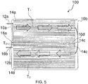
- the temperature of the second set of heat exchange tubes 14b at the interface between the second set of heat exchange tubes 14b and the intermediate tubes 14c is T 2 due to the heat exchange fluid at temperature T 2 flowing there through.
- the difference in temperature of the heat exchange fluid passing through the first set of heat exchange tubes 14a and the second set of heat exchange tubes 14b is due to the heat exchange fluid rejecting heat to the air surrounding the first set of heat exchange tubes 14a as the heat exchange fluid passes through the first set of heat exchange tubes 14a. Since, the first set of heat exchange tubes 14a receive hot heat exchange fluid to be cooled and the second set of heat exchange tubes 14b receive heat exchange fluid cooled in the first heat exchange tube 14a, the intermediate tubes 14c are at an intermediate temperature T 0 such that T 1 > T 0 > T 2 .
- the first blocking element 16c closes the first end of the intermediate tubes 14c.
- the present invention is not limited to any particular configuration, placement and number of the baffles, the first blocking element as far as the baffles, the first blocking element are capable of preventing fluid flow through the intermediate tubes 14c to prevent high temperature gradient between the heat exchange tubes on different sides of each of the baffles 16a and 16b.
- FIG. 4 illustrates a schematic representation of the heat exchanger 100, wherein a second blocking element 16d prevents the heat exchange fluid collected in the second tank 10b after passing through the first set of heat exchange tube 14a from entering into the intermediate tubes 14c from the second tank 10b. More specifically, the second blocking element 16d blocks entrance to the intermediate tubes 14c from the second tank 10b.
- the second blocking element 16d is a planar plate disposed orthogonally to the intermediate tubes 14c and secured to second end of the intermediate tubes 14c opposite to first end thereof. More specifically, the second blocking element 16d closes the second end of the intermediate tubes 14c.
- the present invention is not limited to any particular configuration of the second blocking element 16d as far as the second blocking element is capable of blocking entrance to the intermediate tubes 14c from the second tank 10b.
Landscapes
- Engineering & Computer Science (AREA)
- Physics & Mathematics (AREA)
- Thermal Sciences (AREA)
- Mechanical Engineering (AREA)
- General Engineering & Computer Science (AREA)
- Heat-Exchange Devices With Radiators And Conduit Assemblies (AREA)
Priority Applications (2)
| Application Number | Priority Date | Filing Date | Title |
|---|---|---|---|
| EP20461536.3A EP3916332A1 (de) | 2020-05-27 | 2020-05-27 | Wärmetauscher mit drossel |
| PCT/EP2021/060045 WO2021239329A1 (en) | 2020-05-27 | 2021-04-19 | Heat exchanger with restrictor |
Applications Claiming Priority (1)
| Application Number | Priority Date | Filing Date | Title |
|---|---|---|---|
| EP20461536.3A EP3916332A1 (de) | 2020-05-27 | 2020-05-27 | Wärmetauscher mit drossel |
Publications (1)
| Publication Number | Publication Date |
|---|---|
| EP3916332A1 true EP3916332A1 (de) | 2021-12-01 |
Family
ID=70861431
Family Applications (1)
| Application Number | Title | Priority Date | Filing Date |
|---|---|---|---|
| EP20461536.3A Withdrawn EP3916332A1 (de) | 2020-05-27 | 2020-05-27 | Wärmetauscher mit drossel |
Country Status (2)
| Country | Link |
|---|---|
| EP (1) | EP3916332A1 (de) |
| WO (1) | WO2021239329A1 (de) |
Citations (7)
| Publication number | Priority date | Publication date | Assignee | Title |
|---|---|---|---|---|
| US20080308264A1 (en) * | 2005-08-04 | 2008-12-18 | Dragi Antonijevic | Multiple Flow Heat Exchanger |
| FR2947331A1 (fr) * | 2009-06-29 | 2010-12-31 | Valeo Systemes Thermiques | Echangeur de chaleur comprenant un faisceau de tubes avec au moins un tube inactif |
| US20150330683A1 (en) * | 2014-05-14 | 2015-11-19 | Delphi Technologies, Inc. | Dual circuit refrigerant condenser |
| EP3246646A1 (de) * | 2016-05-20 | 2017-11-22 | Valeo Systemes Thermiques | Kühler, insbesondere gaskühler eines kühlsystems |
| WO2018020136A1 (fr) * | 2016-07-29 | 2018-02-01 | Valeo Systemes Thermiques | Plaque collectrice pour echangeur de chaleur |
| US20180292138A1 (en) * | 2017-04-05 | 2018-10-11 | Denso Marston Ltd. | Manifold for a heat exchanger |
| US20180363987A1 (en) * | 2015-12-10 | 2018-12-20 | Denso Corporation | Heat exchanger |
-
2020
- 2020-05-27 EP EP20461536.3A patent/EP3916332A1/de not_active Withdrawn
-
2021
- 2021-04-19 WO PCT/EP2021/060045 patent/WO2021239329A1/en not_active Ceased
Patent Citations (7)
| Publication number | Priority date | Publication date | Assignee | Title |
|---|---|---|---|---|
| US20080308264A1 (en) * | 2005-08-04 | 2008-12-18 | Dragi Antonijevic | Multiple Flow Heat Exchanger |
| FR2947331A1 (fr) * | 2009-06-29 | 2010-12-31 | Valeo Systemes Thermiques | Echangeur de chaleur comprenant un faisceau de tubes avec au moins un tube inactif |
| US20150330683A1 (en) * | 2014-05-14 | 2015-11-19 | Delphi Technologies, Inc. | Dual circuit refrigerant condenser |
| US20180363987A1 (en) * | 2015-12-10 | 2018-12-20 | Denso Corporation | Heat exchanger |
| EP3246646A1 (de) * | 2016-05-20 | 2017-11-22 | Valeo Systemes Thermiques | Kühler, insbesondere gaskühler eines kühlsystems |
| WO2018020136A1 (fr) * | 2016-07-29 | 2018-02-01 | Valeo Systemes Thermiques | Plaque collectrice pour echangeur de chaleur |
| US20180292138A1 (en) * | 2017-04-05 | 2018-10-11 | Denso Marston Ltd. | Manifold for a heat exchanger |
Also Published As
| Publication number | Publication date |
|---|---|
| WO2021239329A1 (en) | 2021-12-02 |
Similar Documents
| Publication | Publication Date | Title |
|---|---|---|
| US5720341A (en) | Stacked-typed duplex heat exchanger | |
| KR940007191B1 (ko) | 차량의 열교환기 모듈 | |
| US11603790B2 (en) | Heat exchanger | |
| US20170328637A1 (en) | Heat exchanger with dummy tubes | |
| US8561681B2 (en) | Multiple flow heat exchanger | |
| KR100687637B1 (ko) | 열교환기 | |
| US20170036509A1 (en) | Integrated module of evaporator-core and heater-core for air conditioner | |
| JP2000213889A (ja) | 熱交換器のチュ―ブプレ―ト | |
| EP3916332A1 (de) | Wärmetauscher mit drossel | |
| US12439565B2 (en) | Heat sink assembly and power converter assembly | |
| US12281855B2 (en) | Heat exchanger | |
| EP4023993A1 (de) | Wärmetauscher | |
| EP4023988A1 (de) | Wärmetauscher | |
| JP2004278867A (ja) | 熱交換器のコア部構造 | |
| CN116235017A (zh) | 具有用于减小热应力的装置的热交换器 | |
| EP3943861B1 (de) | Wärmetauscher | |
| EP3816568A1 (de) | Wärmetauscher | |
| US20080230211A1 (en) | Heat Exchangers | |
| EP4023995A1 (de) | Wärmetauscher | |
| KR100661357B1 (ko) | 일체형 열교환기 | |
| EP4474750A1 (de) | Wärmetauscher | |
| EP4464966A1 (de) | Wärmetauscher | |
| EP4407268A1 (de) | Verstärkungseinsatz | |
| US20220357115A1 (en) | Heat exchanger | |
| KR102777715B1 (ko) | 열 교환기 |
Legal Events
| Date | Code | Title | Description |
|---|---|---|---|
| PUAI | Public reference made under article 153(3) epc to a published international application that has entered the european phase |
Free format text: ORIGINAL CODE: 0009012 |
|
| STAA | Information on the status of an ep patent application or granted ep patent |
Free format text: STATUS: THE APPLICATION HAS BEEN PUBLISHED |
|
| AK | Designated contracting states |
Kind code of ref document: A1 Designated state(s): AL AT BE BG CH CY CZ DE DK EE ES FI FR GB GR HR HU IE IS IT LI LT LU LV MC MK MT NL NO PL PT RO RS SE SI SK SM TR |
|
| B565 | Issuance of search results under rule 164(2) epc |
Effective date: 20201103 |
|
| STAA | Information on the status of an ep patent application or granted ep patent |
Free format text: STATUS: REQUEST FOR EXAMINATION WAS MADE |
|
| 17P | Request for examination filed |
Effective date: 20220504 |
|
| RBV | Designated contracting states (corrected) |
Designated state(s): AL AT BE BG CH CY CZ DE DK EE ES FI FR GB GR HR HU IE IS IT LI LT LU LV MC MK MT NL NO PL PT RO RS SE SI SK SM TR |
|
| STAA | Information on the status of an ep patent application or granted ep patent |
Free format text: STATUS: EXAMINATION IS IN PROGRESS |
|
| 17Q | First examination report despatched |
Effective date: 20220713 |
|
| STAA | Information on the status of an ep patent application or granted ep patent |
Free format text: STATUS: THE APPLICATION IS DEEMED TO BE WITHDRAWN |
|
| 18D | Application deemed to be withdrawn |
Effective date: 20221124 |