EP3916408A1 - Akkumulatorüberwachungssystem und -verfahren - Google Patents
Akkumulatorüberwachungssystem und -verfahren Download PDFInfo
- Publication number
- EP3916408A1 EP3916408A1 EP20762090.7A EP20762090A EP3916408A1 EP 3916408 A1 EP3916408 A1 EP 3916408A1 EP 20762090 A EP20762090 A EP 20762090A EP 3916408 A1 EP3916408 A1 EP 3916408A1
- Authority
- EP
- European Patent Office
- Prior art keywords
- cmc
- daisy chain
- transmission path
- control module
- cmcs
- Prior art date
- Legal status (The legal status is an assumption and is not a legal conclusion. Google has not performed a legal analysis and makes no representation as to the accuracy of the status listed.)
- Granted
Links
Images



Classifications
-
- H—ELECTRICITY
- H02—GENERATION; CONVERSION OR DISTRIBUTION OF ELECTRIC POWER
- H02J—ELECTRIC POWER NETWORKS; CIRCUIT ARRANGEMENTS OR SYSTEMS FOR SUPPLYING OR DISTRIBUTING ELECTRIC POWER; SYSTEMS FOR STORING ELECTRIC ENERGY
- H02J7/00—Circuit arrangements for charging or discharging batteries or for supplying loads from batteries
- H02J7/80—Circuit arrangements for charging or discharging batteries or for supplying loads from batteries including monitoring or indicating arrangements
-
- G—PHYSICS
- G01—MEASURING; TESTING
- G01R—MEASURING ELECTRIC VARIABLES; MEASURING MAGNETIC VARIABLES
- G01R31/00—Arrangements for testing electric properties; Arrangements for locating electric faults; Arrangements for electrical testing characterised by what is being tested not provided for elsewhere
- G01R31/36—Arrangements for testing, measuring or monitoring the electrical condition of accumulators or electric batteries, e.g. capacity or state of charge [SoC]
- G01R31/396—Acquisition or processing of data for testing or for monitoring individual cells or groups of cells within a battery
-
- G—PHYSICS
- G01—MEASURING; TESTING
- G01R—MEASURING ELECTRIC VARIABLES; MEASURING MAGNETIC VARIABLES
- G01R31/00—Arrangements for testing electric properties; Arrangements for locating electric faults; Arrangements for electrical testing characterised by what is being tested not provided for elsewhere
- G01R31/36—Arrangements for testing, measuring or monitoring the electrical condition of accumulators or electric batteries, e.g. capacity or state of charge [SoC]
- G01R31/371—Arrangements for testing, measuring or monitoring the electrical condition of accumulators or electric batteries, e.g. capacity or state of charge [SoC] with remote indication, e.g. on external chargers
-
- G—PHYSICS
- G08—SIGNALLING
- G08C—TRANSMISSION SYSTEMS FOR MEASURED VALUES, CONTROL OR SIMILAR SIGNALS
- G08C25/00—Arrangements for preventing or correcting errors; Monitoring arrangements
-
- H—ELECTRICITY
- H01—ELECTRIC ELEMENTS
- H01M—PROCESSES OR MEANS, e.g. BATTERIES, FOR THE DIRECT CONVERSION OF CHEMICAL ENERGY INTO ELECTRICAL ENERGY
- H01M10/00—Secondary cells; Manufacture thereof
- H01M10/42—Methods or arrangements for servicing or maintenance of secondary cells or secondary half-cells
- H01M10/4207—Methods or arrangements for servicing or maintenance of secondary cells or secondary half-cells for several batteries or cells simultaneously or sequentially
-
- H—ELECTRICITY
- H01—ELECTRIC ELEMENTS
- H01M—PROCESSES OR MEANS, e.g. BATTERIES, FOR THE DIRECT CONVERSION OF CHEMICAL ENERGY INTO ELECTRICAL ENERGY
- H01M10/00—Secondary cells; Manufacture thereof
- H01M10/42—Methods or arrangements for servicing or maintenance of secondary cells or secondary half-cells
- H01M10/425—Structural combination with electronic components, e.g. electronic circuits integrated to the outside of the casing
-
- H—ELECTRICITY
- H01—ELECTRIC ELEMENTS
- H01M—PROCESSES OR MEANS, e.g. BATTERIES, FOR THE DIRECT CONVERSION OF CHEMICAL ENERGY INTO ELECTRICAL ENERGY
- H01M10/00—Secondary cells; Manufacture thereof
- H01M10/42—Methods or arrangements for servicing or maintenance of secondary cells or secondary half-cells
- H01M10/48—Accumulators combined with arrangements for measuring, testing or indicating the condition of cells, e.g. the level or density of the electrolyte
- H01M10/482—Accumulators combined with arrangements for measuring, testing or indicating the condition of cells, e.g. the level or density of the electrolyte for several batteries or cells simultaneously or sequentially
-
- H—ELECTRICITY
- H02—GENERATION; CONVERSION OR DISTRIBUTION OF ELECTRIC POWER
- H02J—ELECTRIC POWER NETWORKS; CIRCUIT ARRANGEMENTS OR SYSTEMS FOR SUPPLYING OR DISTRIBUTING ELECTRIC POWER; SYSTEMS FOR STORING ELECTRIC ENERGY
- H02J7/00—Circuit arrangements for charging or discharging batteries or for supplying loads from batteries
- H02J7/50—Circuit arrangements for charging or discharging batteries or for supplying loads from batteries acting upon multiple batteries simultaneously or sequentially
-
- H—ELECTRICITY
- H04—ELECTRIC COMMUNICATION TECHNIQUE
- H04Q—SELECTING
- H04Q9/00—Arrangements in telecontrol or telemetry systems for selectively calling a substation from a main station, in which substation desired apparatus is selected for applying a control signal thereto or for obtaining measured values therefrom
-
- G—PHYSICS
- G01—MEASURING; TESTING
- G01R—MEASURING ELECTRIC VARIABLES; MEASURING MAGNETIC VARIABLES
- G01R31/00—Arrangements for testing electric properties; Arrangements for locating electric faults; Arrangements for electrical testing characterised by what is being tested not provided for elsewhere
- G01R31/08—Locating faults in cables, transmission lines, or networks
- G01R31/088—Aspects of digital computing
-
- G—PHYSICS
- G01—MEASURING; TESTING
- G01R—MEASURING ELECTRIC VARIABLES; MEASURING MAGNETIC VARIABLES
- G01R35/00—Testing or calibrating of apparatus covered by the other groups of this subclass
-
- H—ELECTRICITY
- H01—ELECTRIC ELEMENTS
- H01M—PROCESSES OR MEANS, e.g. BATTERIES, FOR THE DIRECT CONVERSION OF CHEMICAL ENERGY INTO ELECTRICAL ENERGY
- H01M10/00—Secondary cells; Manufacture thereof
- H01M10/42—Methods or arrangements for servicing or maintenance of secondary cells or secondary half-cells
- H01M10/425—Structural combination with electronic components, e.g. electronic circuits integrated to the outside of the casing
- H01M2010/4271—Battery management systems including electronic circuits, e.g. control of current or voltage to keep battery in healthy state, cell balancing
-
- H—ELECTRICITY
- H01—ELECTRIC ELEMENTS
- H01M—PROCESSES OR MEANS, e.g. BATTERIES, FOR THE DIRECT CONVERSION OF CHEMICAL ENERGY INTO ELECTRICAL ENERGY
- H01M10/00—Secondary cells; Manufacture thereof
- H01M10/42—Methods or arrangements for servicing or maintenance of secondary cells or secondary half-cells
- H01M10/425—Structural combination with electronic components, e.g. electronic circuits integrated to the outside of the casing
- H01M2010/4278—Systems for data transfer from batteries, e.g. transfer of battery parameters to a controller, data transferred between battery controller and main controller
-
- H—ELECTRICITY
- H04—ELECTRIC COMMUNICATION TECHNIQUE
- H04Q—SELECTING
- H04Q2209/00—Arrangements in telecontrol or telemetry systems
- H04Q2209/30—Arrangements in telecontrol or telemetry systems using a wired architecture
-
- H—ELECTRICITY
- H04—ELECTRIC COMMUNICATION TECHNIQUE
- H04Q—SELECTING
- H04Q2209/00—Arrangements in telecontrol or telemetry systems
- H04Q2209/80—Arrangements in the sub-station, i.e. sensing device
- H04Q2209/82—Arrangements in the sub-station, i.e. sensing device where the sensing device takes the initiative of sending data
- H04Q2209/823—Arrangements in the sub-station, i.e. sensing device where the sensing device takes the initiative of sending data where the data is sent when the measured values exceed a threshold, e.g. sending an alarm
-
- Y—GENERAL TAGGING OF NEW TECHNOLOGICAL DEVELOPMENTS; GENERAL TAGGING OF CROSS-SECTIONAL TECHNOLOGIES SPANNING OVER SEVERAL SECTIONS OF THE IPC; TECHNICAL SUBJECTS COVERED BY FORMER USPC CROSS-REFERENCE ART COLLECTIONS [XRACs] AND DIGESTS
- Y02—TECHNOLOGIES OR APPLICATIONS FOR MITIGATION OR ADAPTATION AGAINST CLIMATE CHANGE
- Y02E—REDUCTION OF GREENHOUSE GAS [GHG] EMISSIONS, RELATED TO ENERGY GENERATION, TRANSMISSION OR DISTRIBUTION
- Y02E60/00—Enabling technologies; Technologies with a potential or indirect contribution to GHG emissions mitigation
- Y02E60/10—Energy storage using batteries
Definitions
- the embodiments of the present disclosure relate to the field of battery monitoring technology, in particular to a storage battery monitoring system and method.
- the storage battery management system mostly use a communication mode based on a CAN bus or single chain daisy chain.
- the daisy chain communication mode may make up for the unpredictability, channel error and blockage and other defects in a CAN bus system to a certain extent, and may improve EMC performance.
- Embodiments of the present disclosure are intended to provide a storage battery monitoring system and method, which can avoid the problem of communication failure due to the occurrence of a fault in a current transmission path and improve safety.
- some embodiments of the present disclosure provide a storage battery monitoring system, including: n cell monitoring cells (CMCs), a control module, and several daisy chain buses; where n is an integer greater than or equal to 2; the n CMCs are configured to monitor a plurality of cell modules electrically connected in a storage battery, and each CMC is configured to monitor at least one of the plurality of cell modules; the n CMCs are connected to the control module through each daisy chain bus; the control module is configured to receive monitoring data of the plurality of cell modules uploaded by the n CMCs through a transmission path formed by at least one daisy chain bus; and the control module is further configured to identify a fault location according to the monitoring data when a fault occurring to the transmission path is detected, and adjust the transmission path according to the fault location so as to receive the monitoring data.
- CMCs cell monitoring cells
- control module is further configured to identify a fault location according to the monitoring data when a fault occurring to the transmission path is detected, and adjust the transmission path according to the fault location
- Some embodiments of the present disclosure also provide a storage battery monitoring method, applied to a control module in a storage battery monitoring system.
- the storage battery monitoring system also includes n cell monitoring cells (CMCs) and several daisy chain buses.
- the n CMCs are configured to monitor a plurality of cell modules electrically connected in a storage battery, and each CMC is configured to monitor its corresponding cell modules.
- the n CMCs are connected to the control module through each daisy chain bus.
- n is an integer greater than or equal to 2.
- the storage battery monitoring method includes: receiving monitoring data of the plurality of cell modules uploaded by the n CMCs through a transmission path formed by at least one daisy chain bus; identifying a fault location according to the monitoring data when a fault occurring to the transmission path is detected; and adjusting the transmission path according to the fault location so as to receive the monitoring data.
- the storage battery monitoring system includes several daisy chain buses, and n CMCs are connected to the control module through each daisy chain bus.
- the control module identifies the fault location according to the monitoring data when the fault occurring to the transmission path is detected, and adjusts the transmission path according to the fault location so as to receive the monitoring data. That is, when the fault occurs to the current transmission path and the monitoring data may not be received, an adjusted transmission path may be used to continue to receive the monitoring data, thus avoiding the problem of communication failure due to the occurrence of the fault in the current transmission path and improving safety.
- control module includes an adaptive controller and a microcontroller.
- the microcontroller receives the monitoring data uploaded by the n CMCs through the adaptive controller; and the adaptive controller is configured to identify the fault location according to the monitoring data when the fault occurring to the transmission path is detected, and adjust the transmission path according to the fault location.
- the adaptive controller is used to adaptively adjust the transmission path, which may reduce a burden on a microprocessor.
- the monitoring data includes state data of the plurality of cell modules collected by the n CMCs and a respective extremum value of each of at least one state parameter in the state data determined by the n CMCs.
- the adaptive controller is further configured to output an alarm signal when it is identified that the respective extremum value reaches a preset alarm threshold.
- the respective extremum value of each of the at least one state parameter is determined by the CMC and then uploaded, so that the control module can obtain the respective extremum value without needing to process the state data after receiving the state data, which may not only reduce the processing burden of the microprocessor, but also improve the timeliness of discovering a storage battery abnormality.
- the respective extremum value of each of the at least one state parameter is judged by the adaptive controller, which may further reduce the running burden of the microcontroller.
- the monitoring data includes state data of the plurality of cell modules collected by the n CMCs and a respective extremum value of each of at least one state parameter in the state data determined by the n CMCs.
- the control module is configured to receive the state data through the transmission path formed by one of the two daisy chain buses, and receive the respective extremum value through the transmission path formed by another of the two daisy chain buses.
- the transmission efficiency may be improved by separately transmitting the state data and the respective extremum value of each of the at least one state parameter of the n cell modules, so that the control module may timely judge whether there is a potential danger through the state parameter.
- the fault location is any position in the transmission path formed by one of the two daisy chain buses; and an adjusted transmission path is a transmission path formed by another of the two daisy chain buses.
- This embodiment provides a case of the fault location and its corresponding adjusted transmission path.
- fault locations which are respectively located on the transmission paths formed by the two daisy chain buses and both between a k-th CMC and a k+1-th CMC; where k is an integer and 1 ⁇ k ⁇ n-1.
- There are two adjusted transmission paths namely, a transmission path formed by a line between the control module and a first CMC, the first CMC and the k-th CMC in one of the two daisy chain buses, and a transmission path formed by a line between the k+1-th CMC and a n-th CMC, and the n-th CMC and the control module in another of the two daisy chain buses.
- This embodiment provides another case of the fault location and its corresponding adjusted transmission path.
- an adjusted transmission path is: a circular transmission path formed by a line between the control module and a first CMC, the first CMC and the k-th CMC, the k+1-th CMC and the k+2+a-th CMC in one of the two daisy chain buses, and between the k-th CMC and the k+1-th CMC, the k+2+a-th CMC and a n-th CMC, and the
- a first embodiment of the present disclosure relates to a storage battery monitoring system, as shown in FIG. 1 , which includes: n cell monitoring cells (CMC), a control module 11 and several daisy chain buses.
- n is an integer greater than or equal to 2.
- the n CMCs are configured to monitor a plurality of cell modules electrically connected in a storage battery in a one-to-one correspondence, and each CMC is configured to monitor at least one of the plurality of cell modules; and the n CMCs are connected to the control module 11 through each daisy chain bus.
- the control module 11 is configured to receive monitoring data of the plurality of cell modules uploaded by the n CMCs through a transmission path formed by at least one daisy chain bus; and the control module 11 is further configured to identify a fault location according to the monitoring data when a fault occurring to the transmission path is detected, and adjust the transmission path according to the fault location so as to receive the monitoring data.
- the storage battery monitoring system includes several daisy chain buses, and the n CMCs are connected to the control module through each daisy chain bus.
- the control module identifies the fault location according to the monitoring data when the fault occurring to the transmission path is detected, and adjusts the transmission path according to the fault location so as to receive the monitoring data. That is, when the fault occurs to the current transmission path and the monitoring data may not be received, an adjusted transmission path may be used to continue to receive the monitoring data, thus avoiding the problem of communication failure due to the occurrence of the fault in the current transmission path and improving safety.
- the storage battery monitoring system in this embodiment is used to monitor a storage battery in an electric vehicle to ensure driving safety. However, it is not limited to this, and the storage battery monitoring system in this embodiment may also be applied to the monitoring of a storage battery in other electrical equipment.
- the storage battery includes n cell modules, which are a cell module 1, a cell module 2, ..., a cell module n.
- the n cell modules are sequentially connected in series, and each cell module includes a plurality of cells connected each other.
- the voltages of the cell module 1, the cell module 2, ... , the cell module n increase sequentially, that is, the cell module 1 is a cell module with a lowest potential in the storage battery, and the cell module n is a cell module with a highest potential in the storage battery.
- the voltages of the cell module 1, the cell module 2, ..., the cell module n may decrease sequentially.
- the n CMCs are a CMC1, a CMC2, ..., a CMCn, and the n CMCs correspond to the n cell modules one by one. That is, a CMCk is connected to both ends of a cell module k to monitor it.
- k is an integer and 1 ⁇ k ⁇ n. Since the CMC1 corresponds to the cell module 1 and the CMCn corresponds to the cell module n, then the CMC1 is a CMC with the lowest potential among the n CMCs, and the CMCn is a CMC with the highest potential among the n CMCs.
- the number of the CMCs in this embodiment is the same as the number of the cell modules, that is, the n CMCs correspond to the n cell modules one by one. However, it is not limited to this, and the number of the CMCs and the cell modules is not limited. If a CMC has relatively more sampling channels, it may also monitor a plurality of cell modules. For example, if a CMC has 12 sampling channels and each cell module includes 4 cells, then the CMC may monitor 3 cell modules. Alternatively, the same cell module may also be monitored by a plurality of CMCs.
- daisy chain buses L1 and L2 there are two daisy chain buses, namely, a daisy chain bus L1 and a daisy chain bus L2.
- the n CMCs are connected to the control module 11 through each daisy chain bus, and a transmission path may be formed based on each daisy chain bus.
- the daisy chain bus may transmit a signal in a differential manner.
- the daisy chain buses L1 and L2 in the figure respectively have two transmission lines, which may be understood as a pair of differential transmission lines.
- the CMC1, the CMC2, ..., and the CMCn are respectively connected to the daisy chain bus L1 and connected to the control module 11 through the daisy chain bus L1, and the CMCn is directly connected to the control module 11. That is, a transmission path 1 formed based on the daisy chain bus L1 includes the n CMCs, a line between adjacent CMCs, and a line between the CMCn and control module 11; and a transmission direction of the monitoring data is from CMC1, CMC2, ..., CMCn, to the control module 11, that is, transmitting from the low potential to the high potential.
- the CMC1, the CMC2, ..., and the CMCn are respectively connected to the daisy chain bus L2 and connected to the control module 11 through the daisy chain bus L2, and the CMC1 is directly connected to the control module 11. That is, a transmission path 2 formed based on the daisy chain bus L2 includes the n CMCs, a line between adjacent CMCs, and a line between the CMC1 and control module 11; and the transmission direction of the monitoring data is from CMCn, CMCn-1, ..., CMC1, to the control module 11, that is, transmitting from the high potential to the low potential.
- the monitoring data of the n cell modules includes state data of the plurality of cell modules and a respective extremum value of each of at least one state parameter in the state data.
- the state data of the plurality of cell modules are respectively collected by the n CMCS, and the state data includes a plurality of state parameters such as voltage, current and temperature of each cell in each cell module.
- Each CMC may also determine the respective extremum value through a step-by-step comparison and upload the respective extremum value to the control module 11.
- a state parameter closely related to the safety performance of the storage battery may be selected and its extremum value may be determined, such as a maximum value of the voltage and a maximum value of the temperature.
- the respective extremum value of each of the at least one state parameter is determined by the CMC and then uploaded, so that the control module 11 can obtain the respective extremum value without needing to process the state data after receiving the state data, which may not only reduce the processing burden of a microprocessor, but also improve the timeliness of discovering a storage battery abnormality.
- the transmission path 1 formed based on the daisy chain bus L1 and the transmission path 2 formed based on the daisy chain bus L2 may both transmit data in two directions, that is, one direction is used to upload the monitoring data of the n cell modules, and another direction is used to issue a control command of the control module to each CMC.
- the transmission directions of the monitoring data of the n cell modules uploaded by the two daisy chain buses may be opposite. However, it is not limited to this. In other examples, the transmission directions of the monitoring data of the n cell modules uploaded by the two daisy chain buses may be the same.
- this embodiment and the following embodiments are illustrated by taking the two daisy chain buses L1, L2 and transmission directions of the two transmission paths respectively formed based on the daisy chain buses L1, L2 being opposite as an example, but are not limited thereto.
- the control module 11 receives the state data of the n cell modules through the transmission path formed based on one of the two daisy chain buses, and receives a maximum voltage value and a maximum temperature value through the transmission path formed based on another of the two daisy chain buses.
- the control module 11 receives the state data of the n cell modules through the transmission path 1 formed based on the daisy chain bus L1, and receives the extremum values of the state parameters through the transmission path 2 formed based on the daisy chain bus L2.
- each CMC determines the extremum values of the state parameters through the step-by-step comparison.
- the CMCn transmits a collected voltage value and temperature value of the cell module n to the CMCn-1.
- the CMCn-1 compares a collected voltage value and temperature value of the cell module n-1 with the received voltage value and temperature value of cell module n respectively, to obtain a relatively large voltage value and a relatively large temperature value, and transmits the relatively large voltage value and the relatively large temperature value to a CMCn-2.
- the CMCn-2 compares a collected voltage value and temperature value of a cell module n-2 with the relatively large voltage value and the relatively large temperature value received from the CMCn-1 respectively, to obtain a re-determined relatively large voltage value and relatively large temperature value, and transmits the re-determined relatively large voltage value and relatively large temperature value to a CMCn-3; and so on, until the CMC1 obtains the maximum voltage value and the maximum temperature value, and uploads the maximum voltage value and the maximum temperature value to the control module 11.
- the state data of the n cell modules and the extremum values of the state parameters are uploaded through the transmission path 1 and the transmission path 2 respectively, which may improve the transmission efficiency of the monitoring data.
- the state data and the extremum values of the state parameters may also be uploaded to the control module 11 through the same transmission path.
- the state data and the extremum values of the state parameters are both uploaded through the transmission path 1 or are both uploaded through the transmission path 2.
- control module 11 may also issue a control command to the n CMCs so as to control each CMC to control its corresponding cell module.
- the control command may be issued to each CMC through the same transmission path.
- the control command may be issued to each CMC through the transmission path 1 or the transmission path 2.
- the control module 11 in this embodiment includes an adaptive controller 111 and a microcontroller 112.
- the adaptive controller 111 has two connection ports, one of which is connected with the daisy chain bus L1, and another is connected with the daisy chain bus L2.
- the adaptive controller 11 is configured to identify a fault location according to the monitoring data when a fault occurring to the transmission path 1 or the transmission path 2 is detected, and adjust the transmission path according to the fault location.
- the microcontroller 112 is connected to the adaptive controller 111 and communicates with the n CMCs through the adaptive controller 111, that is, the microcontroller 112 receives the monitoring data uploaded by the n CMCs or issues the control command to the n CMCs through the adaptive controller 111.
- the communication between the adaptive controller 111 and each CMC, and between the adaptive controller 111 and the microcontroller 112 may use a standard communication protocol such as SPI, CAN, UART, etc., or a non-standard communication protocol (i.e., a protocol defined by a developer's own coding).
- a standard communication protocol such as SPI, CAN, UART, etc.
- a non-standard communication protocol i.e., a protocol defined by a developer's own coding
- control module 11 may only include the microcontroller 112.
- the microcontroller 112 includes two connection ports, one of which is connected with the daisy chain bus L1 and another is connected with the daisy chain bus L2, and performs all functions of the control module 11.
- the state data of the n cell modules are transmitted through the transmission path 1 formed based on the daisy chain bus L1, and the maximum voltage value and the maximum temperature value of the cells are transmitted through the transmission path 2 formed based on the daisy chain bus L2.
- the adaptive controller 111 may upload the monitoring data received from the n CMCs to the microcontroller 112, so that the microcontroller 112 analyzes and processes the monitoring data.
- the adaptive controller 111 may detect whether a fault occurs to the transmission path. For example, the adaptive controller 111 may preset a waiting time for each data reception. After receiving data once, if the next data is received after the waiting time, whether a fault occurs to the transmission path is determined. In addition, the adaptive controller 111 may identify a fault location according to the monitoring data when the fault occurring to the transmission path is detected, and adjust the transmission path according to the fault location to receive the monitoring data.
- the adaptive controller 111 may identify the fault location according to whether the monitoring data may be received normally by controlling a CMC communication port to loop back one by one and issuing a test instruction.
- the transmission path 2 in FIG. 1 is taken as an example:
- the adaptive controller 111 sets a communication port of the CMC1 to a loop-back mode and issues a sampling control instruction. If the adaptive controller 111 may normally receive the state data of the cell module 1 collected by the CMC 1 within a specified time, it indicates that the daisy chain transmission path between the adaptive controller 111 and the CMC 1 has no fault; otherwise, it indicates that there is a fault.
- the adaptive controller 111 When there is no fault in the daisy chain of the CMC1 area, the adaptive controller 111 changes the loop-back mode of the communication port of the CMC1 to a normal mode, and sets the communication port of the CMC2 to the loop-back mode. At the same time, the adaptive controller 111 issues the sampling control instruction. If the state data of the cell module 1 and the cell module 2 collected by the CMC1 and the CMC2 may be normally received within the specified time after the sampling control instruction is issued, it indicates that the daisy chain between the adaptive controller 111 and the CMC2 has no fault; otherwise, it indicates that there is a fault. By analogy, the fault location of the CMC daisy chain is judged one by one in the same way as the above-mentioned daisy chain fault location judgment.
- the fault location is any position in the transmission path formed by one of the two daisy chain buses.
- an adjusted transmission path is a transmission path formed by another of the two daisy chain buses.
- positions P0, P1, P2 and P3 are schematically shown on the daisy chain bus L1, where the position P2 refers to any position between the CMC2 and the CMCn-1, that is, it is schematically shown in FIG. 2 that a fault occurs to the transmission path 1.
- the fault at any position in the transmission path here may be a fault in a line between adjacent CMCs or a line between the CMCn and the control module 11, or a fault in any CMC device itself.
- the adaptive controller 111 issues the control command to the n CMCs to control the n CMCs to transmit the monitoring data (including the state data of the n cell modules and the extremum values of the state parameters) through the daisy chain bus L2, that is, the adjusted transmission path is the transmission path 2 formed based on the daisy chain bus L2. That is, when the fault occurs to the transmission path 1, the state data of the n cell modules originally transmitted through the transmission path 1 formed based on the daisy chain bus L1 is changed to be transmitted through the transmission path 2 formed based on the daisy chain bus L2. It should be noted that FIG. 2 only illustrates the case where the fault occurs to the transmission path 1. If the fault occurs to the transmission path 2, the adjusted transmission path is the transmission path 1 formed based on the daisy chain bus L1.
- FIG. 3 shows positions P3 and P4, where the position P3 is located on the transmission path 1 formed by the daisy chain bus L1, the position P4 is located on the transmission path 2 formed by the daisy chain bus L2, and both the position P3 and the position P4 are located between the CMC1 and the CMC2.
- the fault occurs to the position P3 and the position P4 simultaneously, it indicates that both the transmission path 1 and the transmission path 2 have problems.
- the adaptive controller 111 receives the monitoring data uploaded by the CMC1 through the transmission path 3, and receives monitoring data uploaded by the CMC2 to the CMCn through the transmission path 4, and transmits the received monitoring data from the CMC1, the CMC2 to the CMCn to the microcontroller 112.
- the monitoring data from the CMC1, the CMC2 to the CMCn are uploaded in two paths, so the extremum values of the state parameters may not be obtained by each CMC through the step-by-step comparison, that is, the microcontroller 112 may obtain the extremum values of the state parameters only by identifying and comparing the received monitoring data from the CMC1, the CMC2 to the CMCn.
- the microcontroller 112 issues the control command to the CMC1 through the transmission path 3, and issues the control command to the CMC2 to the CMCn through the transmission path 4.
- FIG. 3 only illustrates the case where the fault location is between the CMC1 and the CMC2; however, it is not limited to this. When the fault occurs to the transmission path 1 and the transmission path 2 between any two adjacent CMCs simultaneously, the adjusted transmission path may be obtained by the above-described methods.
- fault locations which are respectively located on the transmission paths formed by the two daisy chain buses, where one of the fault locations is between the k-th CMC and the k+1-th CMC, and another fault location is between a k+1+a CMC and a k+2+a CMC; where a is an integer greater than or equal to 0, and k+2+a ⁇ n.
- the adjusted transmission path is: a circular transmission path formed between the control module 11 and the first CMC, the first CMC and the k-th CMC, the k+1-th CMC and the k+2+a-th CMC in one of the two daisy chain buses, and between the k+2+a-th CMC and the n-th CMC, and the control module in another of the two daisy chain buses.
- FIG. 4 shows a position P4 and a position P5.
- the position P4 is on the daisy chain bus L2 and between the CMC1 and the CMC2, and the position P5 is on the daisy chain bus L1 between the CMC2 and the CMC3. That is, in the example of FIG. 4 , the value of k is 1 and the value of a is 0.
- the transmission path needs to be re-adjusted so that the monitoring data may be transmitted to the microcontroller 112.
- An adjustment basis is that due to the fault at the position P4, when transmitting between the CMC1 and the CMC2, it is necessary to transfer the monitoring data from a line between the CMC1 and the CMC2 in the daisy chain bus L2 to a line between the CMC1 and the CMC2 in the daisy chain bus L1 for transmission; and due to the fault at the position P5, when transmitting between the CMC2 and the CMC3, it is necessary to transfer the monitoring data from a line between the CMC2 and the CMC3 in the daisy chain bus L1 to a line between the CMC2 and the CMC3 in the daisy chain bus L2 for transmission.
- three different transmission paths may be obtained after adjustment, which are specifically as follows.
- a first transmission path is a circular transmission path 5 formed by lines between the control module 11 and the CMC1, the CMC2 and the CMC3 in the daisy chain bus L2, and lines between the CMC1 and the CMC2, the CMC3 and the CMCn, and the CMCn and the control module 11 in the daisy chain bus L1.
- a second transmission path is a single daisy chain transmission path formed by lines between the control module 11 and the CMC1, the CMC2 and the CMCn in the daisy chain bus L2, and the line between the CMC1 and the CMC2 in the daisy chain bus L1.
- a third transmission path is a single daisy chain transmission path formed by lines between the control module 11 and the CMCn, the CMCn-1 and the CMC3, and the CMC2 and the CMC1 in the daisy chain bus L1, and the line between the CMC3 and the CMC2 in the daisy chain bus L2.
- the following transmission path may be formed.
- a fourth transmission path is a circular transmission path formed by lines between the control module 11 and the CMC1, the CMC1 and the CMC2 in the daisy chain bus L2, and lines between the CMC2 and the CMCn, and the CMCn and the control module 11 in the daisy chain bus L1.
- the adaptive controller 111 may obtain any adjusted transmission path by reconfiguring each CMC; receive the monitoring data uploaded by the n CMCs through the adjusted transmission path, and transmit the monitoring data to the microcontroller 112; where the extremum values of the state parameters may be obtained by a successive comparison of each CMC.
- the microcontroller 112 may also issue the control command to each CMC through the adjusted transmission path.
- the adaptive controller 111 triggers a communication path switching function of a daisy chain control unit within the corresponding CMC, so that the transmission path may be automatically switched after the communication path switching function of the CMC is triggered. Then, the adaptive controller 111 may re-detect whether the adjusted transmission path is normal according to the above-described identification of the fault location.
- the adaptive controller 111 directly sends a control command to control the corresponding CMC to switch the transmission path.
- transmission paths formed by any two of the daisy chain buses may be selected to respectively transmit the monitoring data of the n cell modules and the respective extremum value of each of the at least one state parameter, and the rest of the daisy chain buses are used as a standby daisy chain bus.
- the transmission path may be adjusted according to the above method of this embodiment; or, a transmission path formed by the standby daisy chain bus may be used to transmit the monitoring data.
- a second embodiment of the present disclosure relates to a storage battery monitoring system.
- the second embodiment is substantially the same as the first embodiment, with the main difference that in the second embodiment of present disclosure, the adaptive controller 111 is further configured to output an alarm signal when it is identified that a respective extremum value of each of at least one state parameter reaches a preset alarm threshold.
- the adaptive controller 111 is internally preset with the alarm threshold corresponding to the state parameter.
- the alarm threshold includes a voltage alarm threshold and a temperature alarm threshold.
- the adaptive controller 111 receives a maximum voltage value and a maximum temperature value of a cell, it outputs an alarm signal if it is identified that the maximum voltage value reaches the voltage alarm threshold and/or the maximum temperature value reaches the temperature alarm threshold. That is, as long as one parameter of the maximum voltage value and the maximum temperature value reaches its corresponding alarm threshold, it indicates that the storage battery is in a dangerous state, and the alarm signal is output.
- the adaptive controller is configured to perform judgement on the respective extremum value, which may further reduce the operating burden of the microcontroller.
- the adaptive controller 111 is also connected to a switch 21 in a battery circuit where the storage battery is located; and the alarm signal is a signal for controlling the switch 21 to be turned off. That is, the adaptive controller 111 outputs the alarm signal to the switch 21 to turn off the switch 21, thereby turning off the battery circuit.
- the switch 21 shown in FIG. 5 is connected to the cell module n, that is, set on a high-voltage side of the storage battery, but it is not limited to this. In other examples, the switch may also be set on a low-voltage side of the storage battery, or there may be two switches respectively set on the high-voltage side and the low-voltage side of the storage battery.
- the adaptive controller 111 is connected to the two switches at the same time, and may output the alarm signal to the two switches at the same time.
- modules involved in this embodiment are logic modules.
- a logic unit may be a physical unit, or a part of a physical unit, or a combination of multiple physical units.
- a unit that is not closely related to solving the technical problems proposed in present disclosure is not introduced in this embodiment, but this does not indicate that there are no other units in this embodiment.
- a third embodiment of the present disclosure relates to a storage battery monitoring method, which is applied to a control module in a storage battery monitoring system.
- the storage battery monitoring system includes: n cell monitoring cells (CMC), a control module 11 and several daisy chain buses, where n is an integer greater than or equal to 2.
- the n CMCs are configured to monitor the n cell modules electrically connected in a storage battery in one-to-one correspondence, and each CMC is configured to monitor at least one cell module; and the n CMCs are connected to the control module 11 through each daisy chain bus.
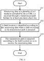
- FIG. 6 shows a flowchart of the storage battery monitoring method of this embodiment, including:
- step 101 monitoring data of a plurality of cell modules uploaded by the n CMCs is received through a transmission path formed by at least one daisy chain bus.
- step 102 a fault location is identified according to the monitoring data when a fault occurring to the transmission path is detected.
- step 103 the transmission path is adjusted according to the fault location so as to receive the monitoring data.
- the storage battery monitoring system includes several daisy chain buses, and n CMCs are connected to the control module through each daisy chain bus.
- the control module identifies the fault location according to the monitoring data when the fault occurring to the transmission path is detected, and adjusts the transmission path according to the fault location so as to receive the monitoring data. That is, when the fault occurs to the current transmission path and the monitoring data may not be received, an adjusted transmission path may be used to continue to receive the monitoring data, thus avoiding the problem of communication failure due to the occurrence of the fault in the current transmission path and improving safety.
- this embodiment is a method embodiment corresponding to the first embodiment, and this embodiment may be implemented in cooperation with the first embodiment.
- the relevant technical details mentioned in the first embodiment are still valid in this embodiment, and in order to reduce repetition, they will not be repeated here.
- the relevant technical details mentioned in this embodiment may also be applied in the first embodiment.
- a fourth embodiment of the present disclosure relates to a storage battery monitoring method.
- the fourth embodiment is substantially the same as the third embodiment, with the main difference that in the fourth embodiment of present disclosure, the adaptive controller may pre-alarm according to a respective extremum value of each of at least one state parameter.
- FIG. 7 is a schematic diagram of the storage battery monitoring method according to the fourth embodiment of the present disclosure, including:
- step 201 monitoring data of a plurality of cell modules uploaded by n CMCs is received through a transmission path formed by at least one daisy chain bus.
- step 202 the adaptive controller outputs an alarm signal when it is identified that the respective extremum value reaches a preset alarm threshold.
- step 203 a fault location is identified according to the monitoring data when a fault occurring to the transmission path is detected.
- step 204 the transmission path is adjusted according to the fault location so as to receive the monitoring data.
- step 201, the step 203, the step 204 are substantially the same as the step 101-the step 103, which will not be repeated here.
- step 202 the execution sequence of step 202 and step 203 is not limited.
- the adaptive controller 111 is internally preset with the alarm threshold.
- the alarm threshold includes a voltage alarm threshold and a temperature alarm threshold.
- step 202 when the adaptive controller 111 receives a maximum voltage value and a maximum temperature value of a cell, it outputs an alarm signal if it is identified that the maximum voltage value reaches the voltage alarm threshold and/or the maximum temperature value reaches the temperature alarm threshold. That is, as long as one parameter of the maximum voltage value and the maximum temperature value reaches its corresponding alarm threshold, it indicates that the storage battery is in a dangerous state, and the alarm signal is output.
- the adaptive controller performs judgement on the respective extremum value, which may further reduce the operating burden of the microcontroller.
- the adaptive controller 111 is also connected to a switch 21 in a battery circuit where the storage battery is located; and the alarm signal is a signal for controlling the switch 21 to be turned off. That is, the adaptive controller 111 outputs the alarm signal to the switch 21 to turn off the switch 21, thereby turning off the battery circuit.
- this embodiment may be implemented in cooperation with the second embodiment.
- the relevant technical details mentioned in the second embodiment are still valid in this embodiment, and the technical effects that may be achieved in the second embodiment may also be achieved in this embodiment. In order to reduce repetition, details are not repeated here. Correspondingly, the relevant technical details mentioned in this embodiment may also be applied in the second embodiment.
- the aforementioned storage medium includes: a U disk, a mobile hard disk, a Read-Only Memory (ROM), a Random Access Memory (RAM), a magnetic disk or an optical disk and other media that may store a program code.
Landscapes
- Engineering & Computer Science (AREA)
- General Chemical & Material Sciences (AREA)
- Manufacturing & Machinery (AREA)
- Chemical & Material Sciences (AREA)
- Chemical Kinetics & Catalysis (AREA)
- Electrochemistry (AREA)
- Physics & Mathematics (AREA)
- General Physics & Mathematics (AREA)
- Power Engineering (AREA)
- Microelectronics & Electronic Packaging (AREA)
- Computer Networks & Wireless Communication (AREA)
- Charge And Discharge Circuits For Batteries Or The Like (AREA)
- Tests Of Electric Status Of Batteries (AREA)
- Secondary Cells (AREA)
Applications Claiming Priority (2)
| Application Number | Priority Date | Filing Date | Title |
|---|---|---|---|
| CN201910142835.3A CN110967641B (zh) | 2019-02-26 | 2019-02-26 | 蓄电池监控系统及方法 |
| PCT/CN2020/076545 WO2020173421A1 (zh) | 2019-02-26 | 2020-02-25 | 蓄电池监控系统及方法 |
Publications (4)
| Publication Number | Publication Date |
|---|---|
| EP3916408A1 true EP3916408A1 (de) | 2021-12-01 |
| EP3916408A4 EP3916408A4 (de) | 2022-03-23 |
| EP3916408C0 EP3916408C0 (de) | 2025-05-21 |
| EP3916408B1 EP3916408B1 (de) | 2025-05-21 |
Family
ID=70028502
Family Applications (1)
| Application Number | Title | Priority Date | Filing Date |
|---|---|---|---|
| EP20762090.7A Active EP3916408B1 (de) | 2019-02-26 | 2020-02-25 | Akkumulatorüberwachungssystem und -verfahren |
Country Status (4)
| Country | Link |
|---|---|
| US (1) | US12216175B2 (de) |
| EP (1) | EP3916408B1 (de) |
| CN (1) | CN110967641B (de) |
| WO (1) | WO2020173421A1 (de) |
Families Citing this family (10)
| Publication number | Priority date | Publication date | Assignee | Title |
|---|---|---|---|---|
| CN110967641B (zh) | 2019-02-26 | 2021-02-19 | 宁德时代新能源科技股份有限公司 | 蓄电池监控系统及方法 |
| CN111562027A (zh) * | 2020-06-22 | 2020-08-21 | 上海羿煜电子科技有限公司 | 一种菊花链二线制温度测量系统及方法 |
| CN111775769B (zh) * | 2020-06-28 | 2022-04-08 | 联合汽车电子有限公司 | 电池管理系统及方法 |
| CN112165423A (zh) * | 2020-09-28 | 2021-01-01 | 北京东土科技股份有限公司 | 一种串行通信方法、电子设备及存储介质 |
| CN112787856B (zh) * | 2020-12-30 | 2023-06-30 | 上海金脉电子科技有限公司 | 故障判断方法、装置、计算机设备以及可读存储介质 |
| CN112630694A (zh) * | 2021-01-26 | 2021-04-09 | 武汉邢仪新未来电力科技股份有限公司 | 一种输电线路故障预警装置 |
| CN114844743A (zh) * | 2022-04-24 | 2022-08-02 | 广州小鹏汽车科技有限公司 | 一种回环菊花链的状态诊断方法 |
| CN118275911B (zh) * | 2023-05-26 | 2025-12-16 | 比亚迪股份有限公司 | 电池总压检测方法、电池总压检测系统、储能系统 |
| CN119316267B (zh) * | 2024-08-27 | 2025-11-14 | 中国第一汽车股份有限公司 | 一种菊花链通信故障诊断方法、主控装置、设备及存储介质 |
| DE102024128097A1 (de) * | 2024-09-27 | 2026-04-02 | Einhell Germany Ag | Akkumulator sowie Verfahren zum Betreiben eines Akkumulators |
Family Cites Families (23)
| Publication number | Priority date | Publication date | Assignee | Title |
|---|---|---|---|---|
| DE4225746A1 (de) * | 1992-08-04 | 1994-02-10 | Hagen Batterie Ag | Schaltungsvorrichtung |
| JP2001310281A (ja) | 2000-04-27 | 2001-11-06 | Sony Corp | コンフィギュレーション取得方法並びに状態検出方法 |
| US8089248B2 (en) * | 2009-04-09 | 2012-01-03 | Ford Global Technologies, Llc | Battery monitoring and control system and method of use including redundant secondary communication interface |
| JP5328574B2 (ja) | 2009-09-04 | 2013-10-30 | 矢崎総業株式会社 | 複数組電池の電圧測定装置 |
| US8015452B2 (en) * | 2010-08-31 | 2011-09-06 | O2Micro International, Ltd. | Flexible bus architecture for monitoring and control of battery pack |
| DE102010062872A1 (de) | 2010-12-13 | 2012-06-14 | Sb Limotive Company Ltd. | Überwachungs-IC Chip für Batteriemanagementeinheit |
| JP2013104842A (ja) | 2011-11-16 | 2013-05-30 | Denso Corp | 電池監視装置 |
| US10365332B2 (en) | 2012-11-02 | 2019-07-30 | Analog Devices Global Unlimited Company | System and method to reduce data handling on lithium ion battery monitors |
| DE102012222720A1 (de) * | 2012-12-11 | 2014-06-12 | Robert Bosch Gmbh | Batteriemanagementsystem und Batteriesystem |
| JP6048299B2 (ja) * | 2013-04-24 | 2016-12-21 | トヨタ自動車株式会社 | 電池監視装置、及び、電池ユニット |
| JP2014217146A (ja) * | 2013-04-24 | 2014-11-17 | トヨタ自動車株式会社 | 電池監視装置、及び、電池ユニット |
| JP6048300B2 (ja) * | 2013-04-24 | 2016-12-21 | トヨタ自動車株式会社 | 電池監視装置、及び、電池ユニット |
| JP5900431B2 (ja) * | 2013-07-18 | 2016-04-06 | トヨタ自動車株式会社 | 電池監視装置、及び、電池ユニット |
| US20150102943A1 (en) * | 2013-10-10 | 2015-04-16 | Datang Nxp Semiconductors Co., Ltd. | Daisy-chain communication bus and protocol |
| JP2015100179A (ja) * | 2013-11-18 | 2015-05-28 | トヨタ自動車株式会社 | 電池監視装置 |
| CN104553852B (zh) * | 2015-01-06 | 2017-02-01 | 重庆长安汽车股份有限公司 | 一种电动汽车电池管理系统混合通信系统 |
| JP6899699B2 (ja) * | 2017-05-12 | 2021-07-07 | 株式会社デンソーテン | 異常検知装置および異常検知方法 |
| JP6989221B2 (ja) | 2017-06-23 | 2022-01-05 | ラピスセミコンダクタ株式会社 | 電池監視システム、信号伝送方法及び半導体装置 |
| KR102605885B1 (ko) * | 2017-06-30 | 2023-11-23 | 테슬라, 인크. | 다중-채널 및 양방향 배터리 관리 시스템 |
| KR101977748B1 (ko) * | 2017-07-20 | 2019-05-13 | 현대오트론 주식회사 | 센싱 칩, 그것을 포함하는 배터리 관리 시스템 및 그것의 동작 방법 |
| CN207311148U (zh) * | 2017-08-18 | 2018-05-04 | 欣旺达电动汽车电池有限公司 | 一种电池管理装置 |
| CN107770025A (zh) | 2017-11-24 | 2018-03-06 | 延锋伟世通电子科技(上海)有限公司 | 一种环形差分通讯的组网装置 |
| CN110967641B (zh) | 2019-02-26 | 2021-02-19 | 宁德时代新能源科技股份有限公司 | 蓄电池监控系统及方法 |
-
2019
- 2019-02-26 CN CN201910142835.3A patent/CN110967641B/zh active Active
-
2020
- 2020-02-25 EP EP20762090.7A patent/EP3916408B1/de active Active
- 2020-02-25 US US17/433,998 patent/US12216175B2/en active Active
- 2020-02-25 WO PCT/CN2020/076545 patent/WO2020173421A1/zh not_active Ceased
Also Published As
| Publication number | Publication date |
|---|---|
| US12216175B2 (en) | 2025-02-04 |
| WO2020173421A1 (zh) | 2020-09-03 |
| CN110967641A (zh) | 2020-04-07 |
| CN110967641B (zh) | 2021-02-19 |
| EP3916408C0 (de) | 2025-05-21 |
| US20220137152A1 (en) | 2022-05-05 |
| EP3916408A4 (de) | 2022-03-23 |
| EP3916408B1 (de) | 2025-05-21 |
Similar Documents
| Publication | Publication Date | Title |
|---|---|---|
| EP3916408B1 (de) | Akkumulatorüberwachungssystem und -verfahren | |
| US10564225B2 (en) | Battery monitoring system, signal transmission method, and semiconductor device for monitoring batteries | |
| CN112015689B (zh) | 串口输出路径切换方法、系统及装置和交换机 | |
| CN111107572A (zh) | 一种冗余备份方法及装置 | |
| EP4057471B1 (de) | Fotovoltaisches system und verfahren zum einstellen eines arbeitszustandes eines optimierers | |
| CN108233391B (zh) | 级联式svg串并行协同通信控制器 | |
| EP2090950A1 (de) | Kritische Vorrichtung mit erhöhter Verfügbarkeit | |
| CN104467195A (zh) | 一种变电站一体化电源监控系统及方法 | |
| CN119231557B (zh) | 电容投切方法、智能电容装置及电子设备 | |
| CN107241141B (zh) | 一种驱动芯片、光模块、光模块的切换方法及pon设备 | |
| US20250079866A1 (en) | Energy storage device, method for energy storage device to determine whether converter device connected thereto has neutral line, and power supply system | |
| CN102271049B (zh) | 通信设备状态设置方法、装置和系统 | |
| CN115498739B (zh) | 储能系统及其控制方法 | |
| US12476482B2 (en) | Excitation fuse device and UPS battery circuit | |
| CN110912388A (zh) | 一种双阀基控制系统的控制方法 | |
| CN215990853U (zh) | 总线网络故障检测装置 | |
| CN104656478B (zh) | 一种多电源模块的控制电路及控制方法 | |
| CN116155704A (zh) | 通信板的异常监测系统、方法和可读存储介质 | |
| CN203480509U (zh) | 一种串联供电装置的基于控制模块的串行通讯架构 | |
| CN115473257B (zh) | 输电系统保护方法、装置、计算机设备、介质、产品 | |
| RU2139629C1 (ru) | Способ и система распознавания наличия канала связи в системе управления решетчатой сети связи | |
| CN103701098B (zh) | 一种用于换流器的控制保护系统及其保护方法 | |
| US20250329811A1 (en) | Self-healing battery pack | |
| CN115792386B (zh) | 绝缘检测方法及系统 | |
| CN218940767U (zh) | 一种电源切换系统和供电电源 |
Legal Events
| Date | Code | Title | Description |
|---|---|---|---|
| STAA | Information on the status of an ep patent application or granted ep patent |
Free format text: STATUS: THE INTERNATIONAL PUBLICATION HAS BEEN MADE |
|
| PUAI | Public reference made under article 153(3) epc to a published international application that has entered the european phase |
Free format text: ORIGINAL CODE: 0009012 |
|
| STAA | Information on the status of an ep patent application or granted ep patent |
Free format text: STATUS: REQUEST FOR EXAMINATION WAS MADE |
|
| 17P | Request for examination filed |
Effective date: 20210825 |
|
| AK | Designated contracting states |
Kind code of ref document: A1 Designated state(s): AL AT BE BG CH CY CZ DE DK EE ES FI FR GB GR HR HU IE IS IT LI LT LU LV MC MK MT NL NO PL PT RO RS SE SI SK SM TR |
|
| A4 | Supplementary search report drawn up and despatched |
Effective date: 20220218 |
|
| RIC1 | Information provided on ipc code assigned before grant |
Ipc: H01M 10/42 20060101ALN20220215BHEP Ipc: G01R 31/08 20200101ALN20220215BHEP Ipc: H04Q 9/00 20060101ALN20220215BHEP Ipc: G08C 19/30 20060101ALI20220215BHEP Ipc: G01R 31/396 20190101ALI20220215BHEP Ipc: H02J 7/00 20060101ALI20220215BHEP Ipc: G01R 31/3842 20190101AFI20220215BHEP |
|
| DAV | Request for validation of the european patent (deleted) | ||
| DAX | Request for extension of the european patent (deleted) | ||
| STAA | Information on the status of an ep patent application or granted ep patent |
Free format text: STATUS: EXAMINATION IS IN PROGRESS |
|
| 17Q | First examination report despatched |
Effective date: 20220722 |
|
| RAP1 | Party data changed (applicant data changed or rights of an application transferred) |
Owner name: CONTEMPORARY AMPEREX TECHNOLOGY(HONG KONG) LIMITED |
|
| REG | Reference to a national code |
Ref country code: DE Ipc: G01R0031371000 Ref legal event code: R079 Ref document number: 602020051646 Country of ref document: DE Free format text: PREVIOUS MAIN CLASS: G01R0031384200 |
|
| GRAP | Despatch of communication of intention to grant a patent |
Free format text: ORIGINAL CODE: EPIDOSNIGR1 |
|
| STAA | Information on the status of an ep patent application or granted ep patent |
Free format text: STATUS: GRANT OF PATENT IS INTENDED |
|
| RIC1 | Information provided on ipc code assigned before grant |
Ipc: G01R 35/00 20060101ALN20241219BHEP Ipc: G01R 31/08 20200101ALN20241219BHEP Ipc: G01R 31/396 20190101ALN20241219BHEP Ipc: H04Q 9/00 20060101ALN20241219BHEP Ipc: G08C 25/00 20060101ALI20241219BHEP Ipc: H01M 10/48 20060101ALI20241219BHEP Ipc: H01M 10/42 20060101ALI20241219BHEP Ipc: H02J 7/00 20060101ALI20241219BHEP Ipc: G01R 31/3842 20190101ALI20241219BHEP Ipc: G01R 31/371 20190101AFI20241219BHEP |
|
| INTG | Intention to grant announced |
Effective date: 20250116 |
|
| GRAS | Grant fee paid |
Free format text: ORIGINAL CODE: EPIDOSNIGR3 |
|
| GRAA | (expected) grant |
Free format text: ORIGINAL CODE: 0009210 |
|
| STAA | Information on the status of an ep patent application or granted ep patent |
Free format text: STATUS: THE PATENT HAS BEEN GRANTED |
|
| AK | Designated contracting states |
Kind code of ref document: B1 Designated state(s): AL AT BE BG CH CY CZ DE DK EE ES FI FR GB GR HR HU IE IS IT LI LT LU LV MC MK MT NL NO PL PT RO RS SE SI SK SM TR |
|
| REG | Reference to a national code |
Ref country code: GB Ref legal event code: FG4D |
|
| REG | Reference to a national code |
Ref country code: CH Ref legal event code: EP |
|
| REG | Reference to a national code |
Ref country code: DE Ref legal event code: R096 Ref document number: 602020051646 Country of ref document: DE |
|
| REG | Reference to a national code |
Ref country code: IE Ref legal event code: FG4D |
|
| U01 | Request for unitary effect filed |
Effective date: 20250612 |
|
| U07 | Unitary effect registered |
Designated state(s): AT BE BG DE DK EE FI FR IT LT LU LV MT NL PT RO SE SI Effective date: 20250624 |
|
| PG25 | Lapsed in a contracting state [announced via postgrant information from national office to epo] |
Ref country code: ES Free format text: LAPSE BECAUSE OF FAILURE TO SUBMIT A TRANSLATION OF THE DESCRIPTION OR TO PAY THE FEE WITHIN THE PRESCRIBED TIME-LIMIT Effective date: 20250521 |
|
| PG25 | Lapsed in a contracting state [announced via postgrant information from national office to epo] |
Ref country code: GR Free format text: LAPSE BECAUSE OF FAILURE TO SUBMIT A TRANSLATION OF THE DESCRIPTION OR TO PAY THE FEE WITHIN THE PRESCRIBED TIME-LIMIT Effective date: 20250822 Ref country code: NO Free format text: LAPSE BECAUSE OF FAILURE TO SUBMIT A TRANSLATION OF THE DESCRIPTION OR TO PAY THE FEE WITHIN THE PRESCRIBED TIME-LIMIT Effective date: 20250821 |
|
| PG25 | Lapsed in a contracting state [announced via postgrant information from national office to epo] |
Ref country code: PL Free format text: LAPSE BECAUSE OF FAILURE TO SUBMIT A TRANSLATION OF THE DESCRIPTION OR TO PAY THE FEE WITHIN THE PRESCRIBED TIME-LIMIT Effective date: 20250521 |
|
| PG25 | Lapsed in a contracting state [announced via postgrant information from national office to epo] |
Ref country code: HR Free format text: LAPSE BECAUSE OF FAILURE TO SUBMIT A TRANSLATION OF THE DESCRIPTION OR TO PAY THE FEE WITHIN THE PRESCRIBED TIME-LIMIT Effective date: 20250521 |
|
| PG25 | Lapsed in a contracting state [announced via postgrant information from national office to epo] |
Ref country code: RS Free format text: LAPSE BECAUSE OF FAILURE TO SUBMIT A TRANSLATION OF THE DESCRIPTION OR TO PAY THE FEE WITHIN THE PRESCRIBED TIME-LIMIT Effective date: 20250821 |
|
| PG25 | Lapsed in a contracting state [announced via postgrant information from national office to epo] |
Ref country code: IS Free format text: LAPSE BECAUSE OF FAILURE TO SUBMIT A TRANSLATION OF THE DESCRIPTION OR TO PAY THE FEE WITHIN THE PRESCRIBED TIME-LIMIT Effective date: 20250921 |
|
| PG25 | Lapsed in a contracting state [announced via postgrant information from national office to epo] |
Ref country code: SM Free format text: LAPSE BECAUSE OF FAILURE TO SUBMIT A TRANSLATION OF THE DESCRIPTION OR TO PAY THE FEE WITHIN THE PRESCRIBED TIME-LIMIT Effective date: 20250521 |
|
| PG25 | Lapsed in a contracting state [announced via postgrant information from national office to epo] |
Ref country code: CZ Free format text: LAPSE BECAUSE OF FAILURE TO SUBMIT A TRANSLATION OF THE DESCRIPTION OR TO PAY THE FEE WITHIN THE PRESCRIBED TIME-LIMIT Effective date: 20250521 |
|
| PG25 | Lapsed in a contracting state [announced via postgrant information from national office to epo] |
Ref country code: SK Free format text: LAPSE BECAUSE OF FAILURE TO SUBMIT A TRANSLATION OF THE DESCRIPTION OR TO PAY THE FEE WITHIN THE PRESCRIBED TIME-LIMIT Effective date: 20250521 |
|
| PLBE | No opposition filed within time limit |
Free format text: ORIGINAL CODE: 0009261 |
|
| STAA | Information on the status of an ep patent application or granted ep patent |
Free format text: STATUS: NO OPPOSITION FILED WITHIN TIME LIMIT |
|
| U20 | Renewal fee for the european patent with unitary effect paid |
Year of fee payment: 7 Effective date: 20260224 |
|
| REG | Reference to a national code |
Ref country code: CH Ref legal event code: L10 Free format text: ST27 STATUS EVENT CODE: U-0-0-L10-L00 (AS PROVIDED BY THE NATIONAL OFFICE) Effective date: 20260402 |
|
| 26N | No opposition filed |
Effective date: 20260224 |