EP3916480A1 - Lichtprojektionssystem - Google Patents
Lichtprojektionssystem Download PDFInfo
- Publication number
- EP3916480A1 EP3916480A1 EP20744642.8A EP20744642A EP3916480A1 EP 3916480 A1 EP3916480 A1 EP 3916480A1 EP 20744642 A EP20744642 A EP 20744642A EP 3916480 A1 EP3916480 A1 EP 3916480A1
- Authority
- EP
- European Patent Office
- Prior art keywords
- light
- switchable diffuser
- condition
- collimated
- projection
- Prior art date
- Legal status (The legal status is an assumption and is not a legal conclusion. Google has not performed a legal analysis and makes no representation as to the accuracy of the status listed.)
- Granted
Links
Images





Classifications
-
- G—PHYSICS
- G02—OPTICS
- G02B—OPTICAL ELEMENTS, SYSTEMS OR APPARATUS
- G02B27/00—Optical systems or apparatus not provided for by any of the groups G02B1/00 - G02B26/00, G02B30/00
- G02B27/42—Diffraction optics, i.e. systems including a diffractive element being designed for providing a diffractive effect
- G02B27/4205—Diffraction optics, i.e. systems including a diffractive element being designed for providing a diffractive effect having a diffractive optical element [DOE] contributing to image formation, e.g. whereby modulation transfer function MTF or optical aberrations are relevant
-
- G—PHYSICS
- G01—MEASURING; TESTING
- G01S—RADIO DIRECTION-FINDING; RADIO NAVIGATION; DETERMINING DISTANCE OR VELOCITY BY USE OF RADIO WAVES; LOCATING OR PRESENCE-DETECTING BY USE OF THE REFLECTION OR RERADIATION OF RADIO WAVES; ANALOGOUS ARRANGEMENTS USING OTHER WAVES
- G01S17/00—Systems using the reflection or reradiation of electromagnetic waves other than radio waves, e.g. lidar systems
- G01S17/88—Lidar systems specially adapted for specific applications
- G01S17/89—Lidar systems specially adapted for specific applications for mapping or imaging
-
- G—PHYSICS
- G01—MEASURING; TESTING
- G01B—MEASURING LENGTH, THICKNESS OR SIMILAR LINEAR DIMENSIONS; MEASURING ANGLES; MEASURING AREAS; MEASURING IRREGULARITIES OF SURFACES OR CONTOURS
- G01B11/00—Measuring arrangements characterised by the use of optical techniques
- G01B11/24—Measuring arrangements characterised by the use of optical techniques for measuring contours or curvatures
- G01B11/25—Measuring arrangements characterised by the use of optical techniques for measuring contours or curvatures by projecting a pattern, e.g. one or more lines, moiré fringes on the object
-
- G—PHYSICS
- G01—MEASURING; TESTING
- G01S—RADIO DIRECTION-FINDING; RADIO NAVIGATION; DETERMINING DISTANCE OR VELOCITY BY USE OF RADIO WAVES; LOCATING OR PRESENCE-DETECTING BY USE OF THE REFLECTION OR RERADIATION OF RADIO WAVES; ANALOGOUS ARRANGEMENTS USING OTHER WAVES
- G01S17/00—Systems using the reflection or reradiation of electromagnetic waves other than radio waves, e.g. lidar systems
- G01S17/88—Lidar systems specially adapted for specific applications
- G01S17/89—Lidar systems specially adapted for specific applications for mapping or imaging
- G01S17/894—Three-dimensional [3D] imaging with simultaneous measurement of time-of-flight at a two-dimensional [2D] array of receiver pixels, e.g. time-of-flight cameras or flash lidar
-
- G—PHYSICS
- G02—OPTICS
- G02F—OPTICAL DEVICES OR ARRANGEMENTS FOR THE CONTROL OF LIGHT BY MODIFICATION OF THE OPTICAL PROPERTIES OF THE MEDIA OF THE ELEMENTS INVOLVED THEREIN; NON-LINEAR OPTICS; FREQUENCY-CHANGING OF LIGHT; OPTICAL LOGIC ELEMENTS; OPTICAL ANALOGUE/DIGITAL CONVERTERS
- G02F1/00—Devices or arrangements for the control of the intensity, colour, phase, polarisation or direction of light arriving from an independent light source, e.g. switching, gating or modulating; Non-linear optics
- G02F1/01—Devices or arrangements for the control of the intensity, colour, phase, polarisation or direction of light arriving from an independent light source, e.g. switching, gating or modulating; Non-linear optics for the control of the intensity, phase, polarisation or colour
- G02F1/13—Devices or arrangements for the control of the intensity, colour, phase, polarisation or direction of light arriving from an independent light source, e.g. switching, gating or modulating; Non-linear optics for the control of the intensity, phase, polarisation or colour based on liquid crystals, e.g. single liquid crystal display cells
- G02F1/133—Constructional arrangements; Operation of liquid crystal cells; Circuit arrangements
- G02F1/1333—Constructional arrangements; Manufacturing methods
- G02F1/1334—Constructional arrangements; Manufacturing methods based on polymer dispersed liquid crystals, e.g. microencapsulated liquid crystals
-
- G—PHYSICS
- G03—PHOTOGRAPHY; CINEMATOGRAPHY; ANALOGOUS TECHNIQUES USING WAVES OTHER THAN OPTICAL WAVES; ELECTROGRAPHY; HOLOGRAPHY
- G03B—APPARATUS OR ARRANGEMENTS FOR TAKING PHOTOGRAPHS OR FOR PROJECTING OR VIEWING THEM; APPARATUS OR ARRANGEMENTS EMPLOYING ANALOGOUS TECHNIQUES USING WAVES OTHER THAN OPTICAL WAVES; ACCESSORIES THEREFOR
- G03B15/00—Special procedures for taking photographs; Apparatus therefor
- G03B15/02—Illuminating scene
-
- G—PHYSICS
- G03—PHOTOGRAPHY; CINEMATOGRAPHY; ANALOGOUS TECHNIQUES USING WAVES OTHER THAN OPTICAL WAVES; ELECTROGRAPHY; HOLOGRAPHY
- G03B—APPARATUS OR ARRANGEMENTS FOR TAKING PHOTOGRAPHS OR FOR PROJECTING OR VIEWING THEM; APPARATUS OR ARRANGEMENTS EMPLOYING ANALOGOUS TECHNIQUES USING WAVES OTHER THAN OPTICAL WAVES; ACCESSORIES THEREFOR
- G03B21/00—Projectors or projection-type viewers; Accessories therefor
- G03B21/14—Details
- G03B21/20—Lamp housings
- G03B21/2006—Lamp housings characterised by the light source
- G03B21/2033—LED or laser light sources
-
- G—PHYSICS
- G02—OPTICS
- G02B—OPTICAL ELEMENTS, SYSTEMS OR APPARATUS
- G02B27/00—Optical systems or apparatus not provided for by any of the groups G02B1/00 - G02B26/00, G02B30/00
- G02B27/10—Beam splitting or combining systems
- G02B27/1086—Beam splitting or combining systems operating by diffraction only
-
- G—PHYSICS
- G03—PHOTOGRAPHY; CINEMATOGRAPHY; ANALOGOUS TECHNIQUES USING WAVES OTHER THAN OPTICAL WAVES; ELECTROGRAPHY; HOLOGRAPHY
- G03B—APPARATUS OR ARRANGEMENTS FOR TAKING PHOTOGRAPHS OR FOR PROJECTING OR VIEWING THEM; APPARATUS OR ARRANGEMENTS EMPLOYING ANALOGOUS TECHNIQUES USING WAVES OTHER THAN OPTICAL WAVES; ACCESSORIES THEREFOR
- G03B35/00—Stereoscopic photography
Definitions
- This disclosure relates to systems and methods projecting light, and selectively controlling the projection of such light using a switchable diffuser arrangement.
- Light projecting technologies are essential for enabling several important device functionalities.
- structured light projecting is deployed in 3D camera modules of mobile phones for recognizing facial features.
- the projected light reflects off the facial features can be captured by a detector and analyzed by algorithms to "perceive" the topology of the face. Accordingly, authentication, emoji generation, image capture orientation, and other various functionalities can be designed based on inputs of the facial feature recognition.
- Light projection is a key step for various applications such as 3D feature detection and 3D mapping.
- multiple light sources and light projection subsystems are deployed in combination with one another to provide 3D feature detection and 3D mapping technology.
- many conventional systems mount both a distinct flood light illumination component and a distinct dot projector component to achieve the desired readings.
- the light produced by the flood light component is broad beam light that spreads substantially as it propagates.
- Flood light is used to illuminate a surface of interest for image capture.
- the light produced by dot projector is narrow beam light configured with substantially parallel rays that do not disperse or diverge with propagation as readily as flood light.
- Using two distinct light sources to achieve both flood light illumination and dot projection is inefficient and results in cumbersome modules that are ill suited for small environments.
- Various embodiments of the present disclosure include light projecting systems and structures, switchable diffusers and other devices.
- a light projecting system comprises: a light projecting system configured to project a plurality of collimated beams of light; a switchable diffuser having a first surface and a second surface, the switchable diffuser coupled to a control source and configured to change from a first state to a second state responsive to the control source being changed from a first condition to a second condition; wherein in the first state the switchable diffuser is configured to receive at least a portion of the plurality of collimated beams of light at the first surface and project a flood light out of the second surface; wherein in the second state the switchable diffuser is configured to permit at least a portion of the plurality of collimated beams of light to propagate out of the second surface as an array; and a processing engine electrically coupled with a non-transitory computer readable medium having machine readable instructions stored thereon, which, when executed by the processing engine, cause the system to: oscillate the control source between the first condition and the second condition in accordance with a first predetermined pattern.
- computer readable medium extends to any medium configured to store machine readable instructions that can be executed by a processing engine.
- machine readable mediums may be found in a microcontroller unit, as system on a chip, or in any combination of the foregoing.
- the light projecting system comprises a vertical-cavity surface-emitting laser (VCSEL) element, a diffraction optics element, and/or a waveguide.
- VCSEL vertical-cavity surface-emitting laser
- the light projecting system comprises a waveguide, the waveguide comprising a surface A and a surface B; the surface A comprises a plurality of grating structures; the waveguide is configured to guide an in-coupled light beam to undergo total internal reflection between the surface A and the surface B; and the grating structures are configured to disrupt the total internal reflection to cause at least a portion of the in-coupled light beam to couple out of the waveguide from the surface A, the portion of the in-coupled light beam coupled out of the waveguide forming out-coupled light beams comprising the plurality of collimated beams of light; the surface A is in an x-y plane comprising an x-direction and a y-direction perpendicular to each other; the in-coupled light beam propagates inside the waveguide substantially along the x-direction of the x-y plane; the out-coupled light beams propagate substantially along a z-direction normal to the x-y plane; the grating structure is each associated with
- the light projecting system comprises a plurality of diodes.
- the system further comprises: a detector configured to capture light information based on one or more flood light reflections off of an object, and array reflections off of an object, wherein: the machine readable instructions, when executed by the processing engine, cause the system to demultiplex light information received at the detector.
- the switchable diffuser comprises a polymer-liquid crystal mixture having a molecular orientation responsive to an applied voltage.
- the switchable diffuser comprises a polymer dispersed liquid crystal.
- the switchable diffuser comprises a polymer network liquid crystal.
- the first predetermined pattern causes the light projecting out of the second surface of the switchable diffuser to comprise alternating bursts of flood light and collimated beams of light achieving a time division multiplexed emission.
- the first voltage condition is an applied voltage of 0V
- the second voltage condition is an applied voltage of between 1 V and 50 V or more.
- the first predetermined pattern comprises switching between the first voltage condition and the second voltage system two or more times during image capture period to achieve a predetermined ratio of flood light projection to collimated light projection.
- the predetermined oscillation pattern is configured to achieve a predetermined projection ratio of flood light to collimated light.
- the predetermined oscillation pattern is configured to achieve a predetermined projection ratio of flood light to collimated light, and the projection ratio is 1:1.
- the predetermined oscillation pattern is configured to achieve a predetermined projection ratio of flood light to collimated light, and the projection ratio is 10:1.
- the predetermined oscillation pattern is configured to achieve a predetermined projection ratio of flood light projection time to collimated light projection time, and the projection ratio is about between 1:1 to 10:1.
- the non-transitory computer readable medium is further configured with machine readable instructions stored thereon, which, when executed by the processing engine, cause the system to: oscillate the control source between the first condition and the second condition in accordance with a second predetermined pattern; and the second predetermined pattern comprises switching between the first voltage condition and the second voltage condition two or more times during a first image capture period to achieve a second predetermined ratio of flood light projection to collimated light projection, and further wherein the second predetermined ratio is different than the first predetermined ratio.
- the non-transitory computer readable medium is further configured with machine readable instructions stored thereon, which, when executed by the processing engine, cause the system to: adjust the time period of one or more of the first image capture period and the second image capture period based on one or more of a detected ambient lighting condition and a transaction security condition.
- a light projecting method comprises: projecting a plurality of collimated beams of light; providing a switchable diffuser having a first surface and a second surface, the switchable diffuser coupled to a control source and configured to change from a first state to a second state responsive to the control source being changed from a first condition to a second condition; wherein in the first state the switchable diffuser is configured to receive at least a portion of the plurality of collimated beams of light at the first surface, and project a flood light out of the second surface; wherein in the second state the switchable diffuser is configured to permit at least a portion of collimated beams of light to propagate out of the second surface as an array; oscillating the control source between the first condition and the second condition in accordance with a first predetermined pattern.
- projecting the plurality of collimated beams of light comprises projecting the plurality of collimated beams of light from a waveguide, the waveguide comprising a surface A and a surface B; the surface A comprises a plurality of grating structures; the waveguide is configured to guide an in-coupled light beam to undergo total internal reflection between the surface A and the surface B; and the grating structures are configured to disrupt the total internal reflection to cause at least a portion of the in-coupled light beam to couple out of the waveguide from the surface A, the portion of the in-coupled light beam coupled out of the waveguide forming out-coupled light beams comprising the plurality of collimated beams of light.
- a system in accordance with the present disclosure includes: a light source configured to generate light (e.g., IR light) ; a projecting structure configured to receive the generated light and responsively project a plurality of collimated beams of light (collectively referred to herein as a light projecting structure); and a switchable diffuser having a first surface and a second surface.
- the switchable diffuser is coupled to a control source such as a voltage source.
- control sources may be implemented with the present technology (e.g., current sources, etc.), the present disclosure regularly refers to a voltage sources by way of example only, and are not intended to be limiting.
- the switchable diffuser is configured to change from a first state to a second state responsive to the voltage source being changed from a first voltage condition (e.g., 0V) to a second voltage condition (e.g., 1-50V).
- a first voltage condition e.g., 0V
- a second voltage condition e.g. 1-50V.
- the switchable diffuser is configured to receive the plurality of columnated beams of light at the first surface, diffuse the plurality of collimated beams of light and project a flood light out of the second surface.
- the switchable diffuser When the switchable diffuser is in the second state, the switchable diffuser is configured to be substantially transparent to the plurality of collimated beams of light incident upon it, and to permit the plurality of collimated beams of light to propagate out of the second surface as an array (e.g., a dot array).
- Example systems may also include a detector configured to capture light information based on one or more flood light reflections off of an object, and dot array reflections off of an object. In some embodiments, the system is configured to demultiplex light information received at the detector.
- an example system of the present disclosure is provided with a controller to manipulate and regulate operations of elements of the system.
- the controller may include a processing engine electrically coupled with a non-transitory computer readable medium having machine readable instructions stored thereon, which, when executed by the processing engine, cause the system to perform various operations.
- the instructions when executed, cause the system to oscillate the voltage source between the first voltage condition and the second voltage condition in accordance with a predetermined oscillation pattern.
- the predetermined oscillation pattern causes the light projecting out of the second surface of the switchable diffuser to comprise alternating bursts of flood light and collimated beams of light achieving a time division multiplexed emission.
- the predetermined oscillation pattern comprises switching between the first voltage condition and the second voltage system two or more times during image capture period to achieve a predetermined ratio of flood light projection to collimated light projection (e.g., from anywhere between 1:1 -10:1, 1:1 -100:1, 1:10 -1:1, or 1:100 - 1:1, etc.).
- the systems of the present disclosure may include a module equipped with both a structured light detector (i.e., a non-ToF detector, e.g., an IR dot array detector) as well as a Time-of-Flight (“ToF”) detector.
- a structured light detector i.e., a non-ToF detector, e.g., an IR dot array detector
- ToF Time-of-Flight
- Both of the structured light detector and the ToF detector may be configured to receive light reflections from the light pulses projected from light projection system, but each may capture, transduce, filter, and/or assess the light differently (or produce signals that may be filtered and/or assessed differently) to derive feature, structure and/or depth information about objects upon which the light projected from light projecting system is incident.
- a light projecting subsystem of a system including both a structured light detector and a ToF detector may nevertheless include a single light source and single switchable diffuser.
- Such light source and switchable diffuser may operate in accordance with one or more features of such elements as discussed herein.
- systems of the present disclosure may include a controller coupled with the structured light detector and the ToF detector, and configured to operate only one of the structured light detector and the ToF detector during a given image capture period - e.g., in "ToF mode” or “non-ToF mode” (ToF mode referring to the situation where only a ToF detector is operating during a given image capture period, and "non-ToF mode” referring to the situation where only a structured light detector is operating during a given image capture period.
- ToF mode referring to the situation where only a ToF detector is operating during a given image capture period
- non-ToF mode referring to the situation where only a structured light detector is operating during a given image capture period
- such a controller may be configured to operate both the structured light detector and the ToF detector together during a given image capture period - e.g., in "hybrid mode" (hybrid mode referring to the case where controller synchronizes operations of the structured light detector and the ToF detector (along with the operation of other elements of the system, e.g., the timing of the switchable diffuser's change of state, the timing of the light sources emissions within the light projecting subsystem of the system, etc.) such that both detectors may coherently operate during a given image capture period.
- hybrid mode hybrid mode referring to the case where controller synchronizes operations of the structured light detector and the ToF detector (along with the operation of other elements of the system, e.g., the timing of the switchable diffuser's change of state, the timing of the light sources emissions within the light projecting subsystem of the system, etc.) such that both detectors may coherently operate during a given image capture period.
- controller may switch between modes - e.g., switch between operation of the system in ToF mode, non-ToF mode, or hybrid mode - based on input from a user (e.g., user selection), or based upon one or more detected condition(s) (e.g., lighting conditions, component status detection, etc).
- modes - e.g., switch between operation of the system in ToF mode, non-ToF mode, or hybrid mode - based on input from a user (e.g., user selection), or based upon one or more detected condition(s) (e.g., lighting conditions, component status detection, etc).
- the technology of the present disclosure may include a system, comprising: an IR detector configured to capture light information based on one or more flood light reflections off of an object, and structured light array reflections off of an object; a Time-of-Flight (ToF) detector configured to measure time differences between the returning light reflections off of a surface of the object (or off of multiple surfaces of different objects), and to enable the determination of one or more depth measures associated with different portions of such surface(s) based on the time differences between different portions of returning light reflections; and a switchable diffuser having a first surface and a second surface, the switchable diffuser coupled to a control source and configured to change from a first state to a second state responsive to the control source being changed from a first condition to a second condition.
- an IR detector configured to capture light information based on one or more flood light reflections off of an object, and structured light array reflections off of an object
- ToF Time-of-Flight
- ToF Time-of-Flight
- the switchable diffuser may be configured to receive at least a portion of the plurality of collimated beams of light at the first surface and project a flood light out of the second surface.
- the switchable diffuser may be configured to permit at least a portion of the plurality of collimated beams of light to propagate out of the second surface as an array.
- the light projecting system includes a processing engine electrically coupled with a non-transitory computer readable medium having machine readable instructions stored thereon, which, when executed by the processing engine, cause the system to: oscillate the control source between the first condition and the second condition in accordance with a first predetermined pattern.
- oscillating the control source between the first condition and the second condition in accordance with a first predetermined pattern causes a plurality of pulses of collimated light to be projected out of the switchable diffuser during a single image capture period.
- the ToF sensor and the structured light sensor are configured to receive reflections of collimated light from one or more of the same pulses of collimated light during a single image capture period.
- the switchable diffuser may be controlled to emit pulses of collimated beams of light that effectuate a modulation of the collimated beams of light that the ToF detector may be configured to resolve.
- modulation may be one or more of pulsed amplitude modulation, pulsed frequency modulation, continuous wave amplitude modulation, and continuous wave frequency modulation.
- the technology provided herein is drawn to methods for performing the functionality described with respect to the example systems hereof.
- FIG. 1 illustrates a diagram depicting an example system for achieving 3D feature detection in accordance with one or more embodiments of the present disclosure.
- a system 100 for achieving 3D feature detection may include a light projecting subsystem 130 and a detector 120 mounted to a module 110 (the module providing structural, optical, and/or electrical support), and a controller 140 in operative communication with module 110 (or one or more elements of module 110).
- light projecting subsystem 130 may be configured to selectively produce both flood light and dot light projections during image capture, avoiding the need to mount and use multiple distinct light projection systems within a given module.
- System 100 may be implemented in various systems or devices, such as mobile phones, computers, pads, wearable devices, vehicles, etc.
- Light projecting subsystem 130 may comprise various elements, including one or more light sources (e.g., a component of a light projecting system 130), shown with more particularity in FIG. 2-5 .
- a light source of such a light projecting subsystem 130 may project structured or columnated light beams of a predetermined or random pattern onto a surface.
- the structured or columnated light may be coupled into and through one or more other optical and optoelectronic elements of the light projecting subsystem 130, such as a lens and/or switchable diffuser element.
- light emitted out of such a switchable diffuser element may be directed toward a surface of an object of interest (e.g., such as a face).
- Reflections of light off of the surface an object may be captured by one or more detectors 120 (e.g., camera sensors).
- Light information captured by detectors 120 may be used to determine depth information (in the case of reflected columnated light, based on shifts and distortions relative to a reference) and object feature information (in the case of reflected flood light, based on wavelength/frequency).
- Various other optically derived parameters may be determined based on the reflected light as captured by the detectors 120.
- the detector is configured to receive reflections of out-coupled beams off multiple locations on a distant object to determine distances of the multiple locations relative to the system, or a designated element of the system, or a designated reference point in relation to the system.
- the light projecting subsystem 130 and detector 120 may be mounted to or otherwise coupled with the same modular structure (e.g., module 110). In some embodiments, the light projecting subsystem 130 and detector 120 are mounted to or otherwise coupled with different modules. In each case, however, detector 120 may be positioned to assume an orientation relative to the light projecting subsystem 130 such that reflections of the projecting subsystem's light off of multiple locations on a distant object may be received by the light sensors of the detector elements. The received reflections may be used to determine distances of the multiple locations relative to a predetermined reference point (e.g., the position of the light projecting subsystem 130).
- a predetermined reference point e.g., the position of the light projecting subsystem 130.
- a virtual flat reflective plane at a single position on the surface of the object may be used as a reference, and reflections of the projected light off the reference can be predetermined as reference reflection beams.
- a surface topology e.g., facial features in the case of a facial surface
- Such determination method may be known as the triangulation method.
- FIG. 2 is a side-view graphical assembly illustration of an example system 100 for projecting both flood light and dot light projections from a light projection subsystem to achieve 3D feature detection in accordance with one or more embodiments of the present disclosure in accordance light in accordance with various embodiments of the present disclosure.
- an example light projecting subsystem 130 may include a light source 132, a light projecting structure 134, and a switchable diffuser 136.
- An example light projecting structure 134 may be a beam array projecting structure, such that the projected beam array forms an array (e.g. a dot array) on a surface (e.g., a 2D surface, a 3D surface, etc.).
- Detector 120 may include a light sensor 122 configured to receive and process the light reflected off of the object being imaged. Detector 120 may in some instances include one or more other optical or optoelectronic elements to filter, channel or otherwise guide desirable light reflections to light sensor 122. Filter 124 is shown in FIG. 2 is an example of an optical element that may be used in connection with light sensor 122.
- Light source 132 may comprise any form of light source.
- light source 132 may emit infrared (IR) light, or any other visible or nonvisible light within any range of the electromagnetic spectrum.
- light source 132 may include a single laser (e.g., an edge-emitting laser, a vertical-cavity surface-emitting laser (VCSEL)), a light-emitting diode (LED) with light collimation, or the like.
- the light source 132 may comprise multiple lasers or diodes (e.g., an edge-emitting laser array, a VCSEL array, a LED array).
- the light source 132 may include one or more of the light sources disclosed in U.S. Application Nos. 16/036,776 , 16/036,801 , and 16/036,814 , each of which is incorporated herein by reference in its entirety.
- Light projecting structure 134 may comprise a waveguide configured to receive light emitted from light source 132, and project a plurality of dot beams.
- light from light source 132 may couple into light projecting structure 134 from any surface or portion of a surface, and/or couple out of the light projecting structure 134 from any surface or portion of a surface.
- Light projecting system 130 may comprise any one or more of the light projecting devices and light projecting structures disclosed in U.S. Application Nos. 16/036,776 , 16/036,801 , and 16/036,814 , each of which is which is incorporated herein by reference in its entirety.
- the light projecting system 130 may comprise a projection lens structure such as projection lens structure 231 of U.S. Application No. 16/036,801 , which may be configured to collimate the light from the light source, and/or to project a random or structured dot array.
- the laser waist of the projected beam array as collimated by the projection lens structure 231 can vary from 10 mm to 1 meter.
- the projection lens structure 231 may collimate the output light to form clear image (e.g., a dot array) at a distance of interest (e.g., in the range of 10cm to 10m depending on the application).
- a distance of interest e.g., in the range of 10cm to 10m depending on the application.
- any of the grating structures disclosed in U.S. Application No. 16/036,801 may be utilized as, with, or in connection with one or more of the light sources 132, projection lenses, and/or waveguides 134 introduced in the present disclosure.
- light projecting subsystem 130 may comprise the system 102 of U.S. Application No. 16/036,801 .
- light projecting subsystem 130 may comprise multiple diodes (e.g., lasers such as an edge-emitting laser array or a VCSEL array, diodes such as a LED array), or any other structure that produces a beam array arranged to impinge on at least a portion of the switchable diffuser material.
- Light projecting subsystem 130 may include one or more of the structures or systems disclosed in U.S. Application Nos. 16/036,776 , 16/036,801 , and 16/036,814 , each of which is incorporated herein by reference in its entirety.
- light projecting subsystem 130 may comprise a diffraction optical element ("DOE") to generate multiple dots in combination with a VCSEL array.
- DOE diffraction optical element
- the DOE in combination therewith may effectively provide a 10X multiplier to generate 1500 dots at the output plane.
- the VCSEL array comprises 300 dots (e.g., beams of collimated light)
- the DOE in combination therewith may effectively provide a 100X multiplier to generate 30000 dots dots at the output plane.
- Any type of DOE may be employed, including DOEs that generate any multiple of dots as the underlying VCSEL array (e.g., 10X - 100X, or greater or less).
- light beams emerging from the light projecting structure 134 may couple out from a surface of the light projecting structure 134. Then, optionally, the light beams may pass through the switchable diffuser 136 to be projected into the space.
- the switchable diffuser 136 may be configured to receive beams from the light source 132 and project the beams (in the same or modified form) into an environment containing a distant object to be imaged. Alternatively, the light beams may be directly projected from the light source 132 into switchable diffuser 136, and the into the space.
- the light projecting structure 134 may comprise various lens or lens combinations (e.g., one to six pieces of separate lenses) for controlling directions of the projected beams.
- Switchable diffuser 136 may comprise any liquid crystal or polymer based mixture having an adjustable molecular orientation responsive to an applied voltage, including, for example, any prior art mixtures.
- switchable diffuser 136 may include any a polymer-liquid crystal mixture, or any other liquid crystal mixture.
- the switchable diffuser 136 may comprise an immiscible mixture of liquid crystal and polymer such as a polymer dispersed liquid crystal (PDLC), or a polymer network liquid crystal (PNLC), or DLP material.
- PDLC polymer dispersed liquid crystal
- PNLC polymer network liquid crystal
- the switchable diffuser 136 may display optical scattering properties when it is not subjected to a substantial electric field.
- PDLC type switchable diffusers 136 may provide such optically scattering properties.
- the concentration of polymer within the liquid crystal may be about between 20% to 60% to achieve scattering. In some embodiments of a PDLC type switchable diffuser 136, the concentration of polymer within the liquid crystal may be about between 60% to 80%. The polymer is cured within the liquid/polymer emulsion such that droplets of liquid crystal separate out within the polymer structure.
- Liquid crystal molecules within each droplet have localized order, but each droplet may be randomly aligned relative to other droplets in the mixture.
- switchable diffuser 136 the combination of small droplet size and isotropic orientation of droplets in the PDLC mixture leads to a highly optically scattering structure in the absence of a substantial electric field.
- the switchable diffuser 136 structure When a substantial electric field is applied across a PDLC type switchable diffuser 136, however, the orientation of the liquid crystal droplets in the mixture changes, reduces the degree of optical scattering that will occur when light is coupled into the structure and passes out the other side. If a sufficient electrical field is applied across a PDLC type switchable diffuser 136, in accordance with one or more embodiments of the present disclosure, the switchable diffuser 136 structure will achieve a substantially transparent state such that in-coupled light will pass through with little to no scattering.
- a PNLC type switchable diffuser 136 may also provide optically scattering/diffusion properties.
- a PNLC type switchable diffuser 136 comprises a network of polymer chains throughout the structure, where concentration of polymer within the within the liquid crystal may be about between 1% to 15%.
- PNLCs may switch between a substantially scattering state and a substantially transparent state under application of appropriate electric fields.
- Switchable diffuser 136 may further comprise additional layers in combination with the scattering elements. Such additional layers may provide polarization stability, structural support, and electric conductivity in connection with the PDLC or PNLC materials.
- switchable diffuser 136 can be controlled to assume one of at least two different states - a diffuser/scattering state and a transparent state - depending on the electric field applied to it.
- the diffuser/scattering state may also be referred herein to as a "first state” or an "off state”
- the transparent state may also be referred to herein as a "second state” or an "on state.”
- system 100 may include a controller 140 that is operatively coupled with one or more of light sensor 122, light source 132 and switchable diffuser 136.
- Controller 140 may be configured to actuate light source 132, causing light source 132 to project light.
- Controller 140 may further be configured to process image information received by light sensor 122 during a time in which controller 140 has actuated light source 132.
- Controller 140 may further be configured to selectively apply an electric field (e.g., a voltage) to the switchable diffuser 136 to achieve switching between an off state (diffusion/scattering state) and an on state (transparent state).
- Controller 140 may be configured to effectuate synchronized operation of light sensor 122, light source 132, and switchable diffuser 136 to achieve a time division multiplexed propagation of flood light and dot light projections.
- controller 140 may be configured to selectively oscillate the application of an electric field across switchable diffuser 136 while light from light source 132 (which optionally will have passed through light projecting structure 134) is being in coupled at a first surface of the switchable diffuser 136 and out coupled through a second surface of switchable diffuser 136.
- Such selective oscillations cause switchable diffuser 136 to switch between and off state and an on state such that during a first period of time the light emitted out of the second surface of switchable diffuser 136 comprises a flood light projection, and that during a second or subsequent period of time the light emitted out of the second surface of switchable diffuser 136 comprises a dot light projection.
- the switchable diffuser 136 may be actuated in any manner and by any combination of elements configured to control the application of an appropriate electric field.
- controller 140 may be coupled with a circuit including a voltage source that may apply a voltage to switchable diffuser 136.
- Conductive elements 142 and/or 144 may be integrated with or otherwise coupled to switchable diffuser 136 to enable an electric field to be applied across switchable diffuser 136.
- Controller 140 may selectively regulate the application of voltage from a voltage source to switchable diffuser 136 through the circuitry connected thereto.
- controller 140 may actuate a switch that connects and/or disconnects a voltage source with one or more of conductive elements 142 and/or 144.
- FIG. 3A illustrates a change in the operation of an example switchable diffuser 136 upon a change in an applied electric field across the switchable diffuser caused by a switch from a first voltage condition to a second voltage condition, where the change between the first voltage condition and second voltage condition (and consequently the "off" state and the “on” state of the switchable diffuser 136) are controlled by controller 140 (not shown).
- the switchable diffuser may remain in its natural condition and act as a diffuser/scatterer of incoming light. This may be referred to as the "off" state.
- the first voltage, V 1 may be 0 V, wherein the "off" state actually corresponds to the voltage being turned “off” from the perspective of the switchable diffuser 136. It should be appreciated however, that the "off" state does not necessarily have to correspond to the voltage of a voltage source being turned off.
- the "off" state of the switchable diffuser 136 may be achieved where the first voltage is about between 0 V and 1 V. In other embodiments, the "off" state of the switchable diffuser 136 may be achieved where the first voltage is any voltage that allows or causes the liquid crystals within the polymeric structure of switchable diffuser to maintain or achieve a molecular arrangement or orientation that causes in-coupled light to become substantially scattered as it passes therethrough - thereby providing a flood light projection.
- light source 132 may provide light that is in-coupled to light projecting structure 134.
- the light projected from light projecting structure 134 may comprise a plurality of dot projections forming a dot array (i.e., a plurality of narrow beams of light projected in a structured or random pattern).
- the dot projections are generally identified by numeral 135 in FIG. 3A .
- the dot projections 135 may be incident upon a first surface of switchable diffuser 136, or otherwise coupled into switchable diffuser 136. Under the first voltage condition, the dot projections 135 that are in coupled to switchable diffuser 136 are scattered by the molecular structure of the switchable diffuser 136.
- switchable diffuser 136 transforms the incoming structured light 135 received at a first surface into flood light projected out of a second surface.
- the flood light projection out of the second surface of switchable diffuser 136a is generally identified by numeral 137 in FIG. 3A .
- switchable diffuser 136 is identified by numeral 136a in the upper image to designate the "off" state (or, in other words, a diffuser/scatterer condition), and is identified by numeral 136b in the lower image to designate the "on" state (or, in other words, a transparent or substantially transparent condition). That is, switchable diffuser 136a (shaded) and 136b (not shaded) in FIG. 3A , are the same switchable diffuser, just in different operating states based on the different electric field or voltage being applied (or not being applied, as the case may be), as between the first voltage condition and the second voltage condition.
- the molecular orientation of the switchable diffuser material may change such that the switchable diffuser is transparent or substantially transparent to the incoming light. This may be referred to as the "on" state.
- the second voltage, V 2 may be about between 1 V and 50 V, wherein the "on" state actually corresponds to the voltage being turned “on” from the perspective of the switchable diffuser 136. It should be appreciated however, that the "on" state does not necessarily have to correspond to the voltage of a voltage source being turned on.
- the aforementioned “off” state does not necessarily have to correspond to the voltage of a voltage source being turned off, and that the "on” state does not necessarily have to correspond to the voltage of a voltage source being turned on.
- the "on” state and the “off” state may be said to assume the opposite states as those discussed above.
- the first voltage condition may achieve an "on” state such that the dot projections that are in coupled to switchable diffuser are allowed to pass through substantially unscattered by the molecular structure of the switchable diffuser
- the second voltage condition may achieve the "off” state such that the dot projections that are in coupled to switchable diffuser are scattered/diffused by the molecular structure of the switchable diffuser and out coupled from the switchable diffuser as flood light.
- the switchable diffuser is substantially transparent to the in coupled dot projections in its natural state or under a first voltage condition (e.g., where the applied voltage is about between 0 V and 1 V) and substantially scattering/diffusive to the in coupled dot projections in its unnatural state or under a second voltage condition (e.g., where the applied voltage is about between 1 V and 50 V). Either such scenario may be referred to as the "on" state or the "off” state, depending on convention desired.
- a first voltage condition e.g., where the applied voltage is about between 0 V and 1 V
- a second voltage condition e.g., where the applied voltage is about between 1 V and 50 V
- the "on" state of the switchable diffuser 136 may be achieved where the second voltage is 0 V. In other embodiments, the "on" state of the switchable diffuser 136 may be achieved where the first voltage is any voltage that allows or causes the liquid crystals within the polymeric structure of switchable diffuser to maintain or achieve a molecular arrangement or orientation that causes the switchable diffuser to be transparent or substantially transparent to incoming light, thus allowing the in-coupled light from light projecting structure 134 and/or light source 132 to pass therethrough without substantial dispersion, diffusion, or other divergence that substantially disrupts the narrow beam dot projection character of the light - thereby providing a structured or random pattern of dot beams to be projected onto a surface of an object and reflected back to a detector 120 (shown in FIGS. 1-2 ).
- light source 132 may continue to provide light that is in-coupled to light projecting structure 134.
- the light projected from light projecting structure 134 continues to comprise a plurality of dot projections (i.e., a plurality of narrow beams of light projected in a structured or random pattern).
- the dot projections 135 may be incident upon a first surface of switchable diffuser 136, or otherwise coupled into switchable diffuser 136.
- the dot projections 135 that are in coupled to switchable diffuser 136 are not substantially scattered by the molecular structure of the switchable diffuser 136.
- switchable diffuser 136 allows the dot light beams 135 received at a first surface to pass through and out of a second surface, continuing onward as narrow beam dot projections.
- the dot projections proceeding out of the second surface of switchable diffuser 136b are generally identified by numeral 138 in FIG. 3A .
- FIG. 3A illustrates (by way of example only) that the switchable diffuser 136 is positioned after the light projecting structure 134 (e.g., projection lens), the switchable diffuser 136 may also be arranged in other positions with respect to the elements of light projecting subsystem 130.
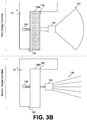
- a switchable diffuser may be positioned between the light source 132 and the projection lens 134, as shown in FIG. 3B (with common numerals representing common elements discussed above with reference to FIG. 3A ).
- the light projection structure 134 and/or the light source 132 is made up of several elements, and the switchable diffuser can be positioned before, between or after any of them in the arrangement.
- the switchable diffuser may be positioned before, between, or after any such elements.
- the light projecting subsystem 130 may comprise a diffraction optical element ("DOE") 139 to generate multiple dots in combination with a VCSEL array 133, and the switchable diffuser 136 may be positioned between them.
- DOE diffraction optical element
- the light source 132 in FIG. 3A or FIG. 3B may comprise the VSCEL array 133a and DOE 133b of FIG. 3C , and a switchable diffuser may be positioned before, between, or after any such elements.
- the configurations shown are merely examples provided for clarity of description, and that other arrangements and variations may be implemented without exceeding the scope of the present disclosure.
- controller 140 may cause operation of the aforementioned elements to be synchronized based on one or more device operating capabilities or requirements, environmental conditions, default or user defined settings, or any other input. For example, if light sensor 122 is controlled to capture image information for a given frame for a period of 1/60 seconds, the controller 140 may control switchable diffuser 136 to switch between an "off" state and an "on” state within the period of time that the image information is captured for a given frame.
- controller 140 may effectuate a switch of the switchable diffuser 136 such that both dot projection reflections and flood projection reflections are received (in time-multiplexed manner, as noted above) by the detector 122 during the period of light capture for the frame.
- controller 140 may be configured to oscillate the electric field applied to the switchable diffuser at a rate that is between 2-100 times faster than the frame rate established for image capture.
- controller 140 may be configured to oscillate the electric field applied to the switchable diffuser at a rate that is between greater than 100 times faster than the frame rate established for image capture.
- FIG. 4 illustrates an example architecture depicting various subcomponents of controller 140 that may, upon execution, enable one or more of the features disclosed herein in connection with one or more other elements of system 100, including any one or more elements of light projection subsystem 130 and detector 120.
- controller 140 may be configured (or operatively coupled) with one or more processing engines 150, and one or more machine readable instructions 160 which, when executed by the one or more processing engines 150, cause one or more of the disclosed features to be effectuated.
- Machine readable instructions 160 may be stored on a machine readable medium.
- the machine readable instructions 160 may have machine readable code comprising an activation component 161, a field manipulation component 162, synchronization component 163, dynamic adjustment component 164, and/or one or more other components 165.
- Activation component 161 may be configured to detect when use of imaging system 100 is desired, and to correspondingly cause the system 100 to activate one or more elements of light projection subsystem 130 and/or detector 120. For example, if a user's mobile phone is equipped with system 100, and the user's input indicates a request for 3D facial recognition (or other 3D topology mapping), activation component 161 may identify the indication provided by the user, and cause system 100 to activate the light source 132 of light projection subsystem 130 and/or detector subsystem 120. Activation component 161 may be further configured to determine an operation status of light projection subsystem 130 and/or detector subsystem 120. If the operation status of light projection subsystem 130 and/or detector subsystem 120 is satisfactory, activation component 161 may activate field manipulation component 162.
- Field manipulation component 162 may be configured cause system 100 to apply an electric field to, adjust an electric field being applied to, or remove an electric field from a switchable diffuser 136 element of light projection subsystem 130.
- field manipulation component 162 may cause controller 140 to apply, adjust or remove a voltage to/from switchable diffuser 136 from a voltage source to which the controller 140 is operatively coupled.
- field manipulation component 162 may cause switchable diffuser 136 two switch back-and-forth between an "off" state (diffusion/scattering state) and an "on" state (transparent state).
- Field manipulation component 162 may be configured to time its operations in accordance with the operation of other elements of system 100, for example, detector 120 and other components of controller 140. In so doing, field manipulation component 162 may draw on information determined, stored, or otherwise provided by synchronization component 163.
- Synchronization component 163 may be configured to determine an operation speed or rate of image capture being performed, or capable of being performed, by detector subsystem 120 and/or controller 140 in connection with detector subsystem 120. Additionally, synchronization component 163 may determine or control the timing of operation of such elements, and informed field manipulation component 162 of the same. For example, as noted above, if light sensor 122 is controlled to capture image information at 60 frames per second (meaning that for a given frame image capture occurs for a period of 1/60 second or less), synchronization component 163 may identify this operation capacity (based on detection or based on pre-determined/stored information) and may further provide a start and/or stop time to either or both of activation component 161 and field manipulation component 162.
- synchronization component 163 may be configured with a clock that can be used in connection with the operations of activation component 161 and field manipulation component 162 (or any other components of system 100), to synchronize functionality such that the desired performance may be achieved.
- the desired performance in a given situation may be pre-determined, or it may be dynamically adjustable given one or more other detectable conditions.
- the dynamically adjustable features of the presently disclosed technology may be enabled, in whole or in part, by a dynamic adjustment component 164.
- Dynamic adjustment component 164 may be configured to detect one or more internal or external conditions or requests that call for an adjustment to any default or otherwise predetermined operation settings of system 100. Dynamic adjustment component 164 may be informed by one or more sensors or detection engines operating in connection with one or more other components 165. For example, a default setting of system 100 may provide that field manipulation component 162 will operate to switch the switchable diffuser 136 between it "on" and "off” state such that, during image capture for an individual frame, the ratio of time for flood light 137 projection to time for dot projection 138 is 1:3.
- dynamic adjustment component 164 may determine that the ratio of time for floodlight 137 projection to time for dot projection 138 should be modified from 1:3 to 1:1 to provide additional flood light 137 illumination on an object within that environment (e.g., a user's face).
- dynamic adjustment component 164 may operate to cause field manipulation component 162 to impose a voltage oscillation pattern on switchable diffuser 136 such that switchable diffuser 136 assumes and "on" state during approximately 1/2 of the image capture time for an individual frame, and assumes an "off" state during the other 1/2 of the image capture time for such frame. Consequently, during 1/2 of the image capture time for a given frame, flood light 137 will be projected out of the second surface of switchable diffuser 136, and during the other 1/2 of the image capture time for a given frame, dot projections 138 will be projected out of the second surface of switchable diffuser 136.
- field manipulation component 162 may operate responsively to one or more of dynamic adjustment component 164 and/or synchronization component 163, and/or activation component 161, and/or any other components 165 of system 100.
- dynamic adjustment component 164 may be configured to detect when a given situation calls for higher than default resolution and/or timing for facial recognition. For example, if a user of a mobile phone equipped with system 100 is simply trying to unlock their device using facial recognition, the default resolution may simply correspond to a ratio of time for flood light 137 projection to time for dot projection 138 of 1:3 (for each frame) and require that the image information be collected for 0.5 seconds at 60 frames per second.
- dynamic adjustment component 164 may determine that under such conditions a higher resolution facial rendering is required to achieve an adequate matching condition (e.g., with a stored template of the user's facial topology) to authorize the login or the purchase. Under such conditions, dynamic adjustment component 164 may be configured to cause field manipulation component 162 and or synchronization component 163 to make necessary adjustments so as to enable system 100 to generate or obtain higher resolution 3D information that satisfies the higher security requirements associated with the detected login request or purchase request.
- dynamic adjustment component 164 may require field manipulation component 162 to provide more or less floodlight as compared to dot projections for a first period of image capture, and then to cause an adjustment to such floodlight and dot projection proportions for a second period of image capture. Additionally or alternatively, dynamic adjustment component 164 may require that field manipulation component operate for a longer period of time than otherwise set by default. Similarly, dynamic adjustment component 164 may cause activation component 161 and synchronization component 163 to operate for a longer period of time than otherwise set by default for circumstances where higher security is demanded, and consequently high-resolution image information is required. Any and all of such settings and dynamic adjustments may be preset or predefined by a user, or may be learned over time with repetitive use and training of system 100 in various circumstances.
- controller 140 may control switchable diffuser 136 to switch between an "off" state and an "on” state within the period of time that the image information is captured for a given frame. It is also noted here that controller 140 (e.g., via field manipulation component 162) may cause switchable diffuser 136 to switch between an off state and an on state multiple times during image capture for a given frame. That is, for a given frame capture, controller 140 may effectuate a switch of the switchable diffuser 136 such that both dot projection reflections and flood projection reflections are received (in time-division multiplexed manner, as noted above) by the detector 122 during the period of light capture for the frame.
- controller 140 may be configured to oscillate the electric field applied to the switchable diffuser at a rate that is between 2-100 times faster than the frame rate established for image capture. In some embodiments, controller 140 may be configured to oscillate the electric field applied to the switchable diffuser at a rate that is between greater than 100 times faster than the frame rate established for image capture.
- Synchronization component 163 may operate to inform other elements of system 100 as to the timing of light projections, thereby informing the processing of light information received by the light sensor 122 of detector subsystem 120 such that system 100 may discriminate or otherwise distinguish between light information that is associated with reflected floodlight, and light information that is associated with reflected dot projections, and adjust other operations accordingly.
- synchronization component 163 may provide multiplexing functionality in connection with received image information.
- synchronization component 163 may enable detector 120 to capture IR image photos (e.g., heat signature photos) during time periods of flood light projection, and IR dot array photos during IR dot projections.
- any one or more of activation component 161, field manipulation component 162, synchronization component 163, dynamic adjustment component 164, and/or other components 165 may be implemented in either hardware or software or both.
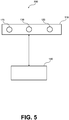
- FIG. 5 illustrates a system 500 that may be implemented in accordance with one or more embodiments of the present disclosure.
- System 500 is depicted as a variation of system 100, where module 110 is equipped with both a non-ToF light detector (e.g., detector 120, discussed above), as well as a Time of Flight detector, ToF detector 170.
- Detector 120 may capture/transduce/filter reflections of light (structured light and/or flood light) off of the surface(s) an object(s) upon which the light is projected (e.g., a face).
- Light information captured by detector 120 may be used to determine depth information (in the case of reflected columnated light, based on shifts and distortions relative to a reference) and object feature information (in the case of reflected flood light, based on wavelength/frequency).
- the ToF detector 170 operates based on the pulsed time-of-flight principle (rather than being primarily based on shifts, distortion, frequency, or wavelength).
- the pulsed time-of-flight principle recognizes that the time light needs to travel from a light source to an object and back to a detector changes depending on how far away the object is from the light source and/or ToF detector - i.e., the further the distance the light has to travel through space, the longer amount of time it will take for the light to reach the ToF detector.
- ToF detection both the light source and the ToF detector must be synchronized such that distances can be extracted and calculated from the time differences detected.
- the timing details of the light pulse generated by the light source and the timing details of the light received back at the ToF detector should be tightly controlled and/or monitored.
- the resolution of ToF based images enhances with enhanced monitoring and/or control of timing.
- module 110 is provided with both a non-ToF detector 120 as well as a ToF detector 170. Both are configured to receive light reflections from the light projected from light projection system 130, but each assesses the light differently (or produce signals that may be assessed differently) to derive depth information and/or other structural features about objects upon which the light projected from light projecting system 130 is incident.
- light projecting subsystem 130 of system 500 may include a single light source and a switchable diffuser 136. Such light source and switchable diffuser 136 may operate in accordance with one or more features of such elements as discussed herein with reference to FIGs. 1-4 .
- controller 140 may be configured to operate only one of detector 120 and ToF detector 170 during a given image capture period - e.g., in "ToF mode” or “non-ToF mode” (ToF mode referring to the situation where only ToF detector 170 is operating during a given image capture period, and "non-ToF mode” referring to the situation where only detector 120 is operating during a given image capture period (e.g. in accordance with FIGs. 1-4 ).
- controller 140 may be configured to operate both detector 120 and ToF detector 170 together during a given image capture period - e.g., in "hybrid mode" (hybrid mode referring to the case where controller 140 synchronizes operations of detector 120, ToF detector 170 (along with other elements of system 500, e.g., light projecting subsystem 130) such that both detectors are in operation during a given image capture period.
- hybrid mode referring to the case where controller 140 synchronizes operations of detector 120, ToF detector 170 (along with other elements of system 500, e.g., light projecting subsystem 130) such that both detectors are in operation during a given image capture period.
- controller 140 may effectuate operation of system 500 in ToF mode, non-ToF mode, or hybrid mode based on input from a user (e.g., user selection).
- controller 140 may be configured to effectuate a switch between modes depending on one or more detected condition(s), e.g., lighting conditions, component status detection, etc. For instance, if dynamic adjustment component 164 of controller 140 detects that ambient light conditions in the external environment of system 100 provide poor illumination (e.g., an illumination that falls beneath a predefined threshold (e.g.
- dynamic adjustment component 164 may determine that ToF imaging will generate a higher resolution image than the image generated via detector 120. In response to such a determination, controller 140 may effectuate operation of the system such that module 110 operates in ToF mode.
- an element of system 500 detects that the object being imaged is within a predetermined distance from the detector within which the structured light detection via detector 120 will generate an image with a higher resolution that is superior to that provided by ToF detection (e.g., an object is within a predefined distance (e.g., within 1 meter)
- dynamic adjustment component 164 may determine that detector 120 will generate a higher resolution image than the image generated via ToF detector 170. In response to such a determination, controller 140 may effectuate operation of the system such that module 110 operates in non-ToF mode.
- dynamic adjustment component 164 may determine that the best image information may be obtained by operating detector 120 and ToF detector 170 in concert (e.g., simultaneously, or in a time-multiplexed manner) during a given image capture period. In response to such a determination, controller 140 may effectuate operation of the system such that module 110 operates in hybrid mode. Such a determination may be made based on predetermined rules/criteria with regard to such detected conditions, as may be set for a given application.
- controller 140 may regulate and/or monitor the timing of switchable diffuser's switch between states (and thereby monitor the switching between flood light projections and structured array light projections), and treat one or the other as the "pulse" to track for purposes of computing time-of-flight differences in connection with light received at the ToF detector 170. That is, controller 140 - via synchronization component 163 or another component - may synchronize operation of detector 120 and ToF detector 170 with the timing of the different light projections (e.g., structured dot array projections, flood light projections, etc.) propagating from light projection subsystem 130.
- the different light projections e.g., structured dot array projections, flood light projections, etc.
- the time-multiplexed light information obtained via detector 120 and ToF detector 170 may be coherently de-multiplexed and/or otherwise resolved by system 500.
- the imaging information obtained via detector 120 and ToF detector 170 during hybrid mode operation may be combined to generate a composite image.
- hybrid mode operations may tuned to optimize resolution (or enhance resolution) based on the one or more conditions detected. For example, if dynamic adjustment component 164 of controller 140 detects that ambient light conditions in the external environment of system 500 provide an illumination quality that make hybrid mode desired, but illumination should be enhanced by flood light in a proportion greater than a 1:1 (flood light projection to structured array projection ratio), dynamic adjustment component 164 may determine not only that hybrid mode should be activated/selected, but further that the ratio of time for floodlight projections to time for structured dot projections should be modified from 1:1 to 2:1 to provide additional flood light illumination on an object within that environment (e.g., a user's face).
- synchronization component 163 may be configured to make corresponding adjustments to aid controller 140 in resolving the light information as transduced by detector 120 and ToF detector 170 during hybrid mode. For example, synchronization component 163 may determine an operation speed or rate of image capture set to be performed by detector subsystem 120, ToF detector 170 and/or controller 140, and may facilitate control of the timing of operation or initialization of such elements. Synchronization component 163 and/or dynamic adjustment component 164 may inform field manipulation component 162 of the same.
- synchronization component 163 may identify this operation capacity (based on detection or based on pre-determined/stored information) and may further provide a start and/or stop time to either or both of activation component 161 and field manipulation component 162.
- synchronization component 163 may be configured with a clock that can be used in connection with the operations of activation component 161, field manipulation component 162, dynamic adjustment component 163 (or any other components of system 500), to synchronize functionality such that the desired performance may be achieved in a given scenario.
- the desired performance in a given situation may be pre-determined, or it may be dynamically adjustable, in whole or in part, by a dynamic adjustment component 164 based on one or more detectable conditions.
- Synchronization component 163 may, in hybrid mode, operate to inform other elements of system 500 as to the timing of light projections, thereby informing the processing of light information received by detector subsystem 120 and ToF detector 170 such that system 500 may not only discriminate or otherwise distinguish between light information that is associated with reflected floodlight, and light information that is associated with reflected dot projections, but also may distinguish light information associated with ToF derivations from light information associated with non-ToF derivations, and adjust other operations accordingly.
- synchronization component 163 may provide multiplexing functionality in connection with received image information.
- synchronization component 163 may enable detector 120 to capture IR image photos (e.g., heat signature photos) during time periods of flood light projection, and IR dot array photos during IR dot projections, and in the same image capture period enable ToF detector 170 to capture temporally resolved image photos during time periods of IR dot projections (e.g., or other structured array projections), leveraging the structured light bursts as the "pulses" of light in accordance with the pulsed time-of-flight principal.
- IR image photos e.g., heat signature photos
- ToF detector 170 to capture temporally resolved image photos during time periods of IR dot projections (e.g., or other structured array projections)
- synchronization component 163 may be configured to synchronize or otherwise coordinate the ToF detector 170's image capture with detector 120's (e.g., IR detector) image capture, and further synchronize both with with the switchable diffuser 136's switches between "off" and “on” states.
- switchable diffuser 136 may be controlled to output short pulsed of flood light (e.g., 1-100ns) or long pulsed dot light (e.g., 100 ⁇ s-30ms) based on a switch in the applied voltage.
- the ToF detector 170 may be controlled by controller 140 to be pulsed to provide pulsed amplitude modulation, pulsed frequency modulation, and/or continuous wave AM/FM.
- the ToF detector 170 and the structured light detector 120 may be controlled by controller 140 such that they are synchronized to match or otherwise operate in alignment with the time-division multiplexed light (flood light and structured light being time multiplexed together) signals generated by the switchable diffuser.
- controller 140 may be controlled by controller 140 such that they are synchronized to match or otherwise operate in alignment with the time-division multiplexed light (flood light and structured light being time multiplexed together) signals generated by the switchable diffuser.
- controller 140 may be extended to embodiments employing ToF detector 170, including as discussed above with respect to synchronization component 163 and dynamic adjustment component 164.
- system embodiments in accordance with system 500, or variations thereof, may enable the capture of 3D ToF photos/image information in synchronization with 2D IR dot photos/image information.
- the systems of the present disclosure may provide enhance security features to ensure, for example, that the object being imaged is the true 3D object and not a 2D rendition of the object used to spoof the system.
- the ToF detector may be controlled by controller 140 to be continuously or periodically calibrated.
- FIG. 6 illustrates a process flow diagram depicting a method that may be implemented in accordance with one or more embodiments of the present disclosure.
- method 200 comprises receiving light generated by a light source light and responsively projecting a plurality of collimated beams of light.
- method 200 comprises: providing a switchable diffuser having a first surface and a second surface, the switchable diffuser coupled to a voltage source and configured to change from a first state to a second state responsive to the voltage source being changed from a first voltage condition to a second voltage condition.
- method 200 comprises: oscillating the voltage source between the first voltage condition and the second voltage condition in accordance with a predetermined oscillation pattern, the voltage oscillations causing alternating flood light and dot array projections to be emitted from the second surface of the switchable diffuser in a time-division multiplexed manner.
- method 200 comprises: detecting, at a light sensor, light information from the alternating flood light and dot array light reflections off of an object, wherein the light sensor is synchronized with the voltage oscillations and/or the alternations in flood light and dot array light projection.
- method 200 comprises: demultiplexing light information detected at the light sensor.
- method 200 comprises: generating a 3D map of the object based on the demultiplexed light information.
- the term "or" may be construed in either an inclusive or exclusive sense. Moreover, plural instances may be provided for resources, operations, or structures described herein as a single instance. Additionally, boundaries between various resources, operations, engines, and data stores are somewhat arbitrary, and particular operations are illustrated in a context of specific illustrative configurations. Other allocations of functionality are envisioned and may fall within a scope of various embodiments of the present disclosure. In general, structures and functionality presented as separate resources in the exemplary configurations may be implemented as a combined structure or resource. Similarly, structures and functionality presented as a single resource may be implemented as separate resources. These and other variations, modifications, additions, and improvements fall within a scope of embodiments of the present disclosure as represented by the appended claims. The specification and drawings are, accordingly, to be regarded in an illustrative rather than a restrictive sense.
Landscapes
- Physics & Mathematics (AREA)
- General Physics & Mathematics (AREA)
- Engineering & Computer Science (AREA)
- Optics & Photonics (AREA)
- Remote Sensing (AREA)
- Nonlinear Science (AREA)
- Computer Networks & Wireless Communication (AREA)
- Electromagnetism (AREA)
- Radar, Positioning & Navigation (AREA)
- Chemical & Material Sciences (AREA)
- Mathematical Physics (AREA)
- Crystallography & Structural Chemistry (AREA)
- Dispersion Chemistry (AREA)
- Computer Vision & Pattern Recognition (AREA)
- Measurement Of Optical Distance (AREA)
- Length Measuring Devices By Optical Means (AREA)
- Circuit Arrangement For Electric Light Sources In General (AREA)
Applications Claiming Priority (2)
| Application Number | Priority Date | Filing Date | Title |
|---|---|---|---|
| CN201910073808.5A CN109901353B (zh) | 2019-01-25 | 2019-01-25 | 一种光投射系统 |
| PCT/CN2020/070824 WO2020151493A1 (zh) | 2019-01-25 | 2020-01-08 | 一种光投射系统 |
Publications (3)
| Publication Number | Publication Date |
|---|---|
| EP3916480A1 true EP3916480A1 (de) | 2021-12-01 |
| EP3916480A4 EP3916480A4 (de) | 2022-04-06 |
| EP3916480B1 EP3916480B1 (de) | 2023-04-19 |
Family
ID=66944200
Family Applications (1)
| Application Number | Title | Priority Date | Filing Date |
|---|---|---|---|
| EP20744642.8A Active EP3916480B1 (de) | 2019-01-25 | 2020-01-08 | Lichtprojektionssystem |
Country Status (3)
| Country | Link |
|---|---|
| EP (1) | EP3916480B1 (de) |
| CN (4) | CN113253474A (de) |
| WO (1) | WO2020151493A1 (de) |
Cited By (2)
| Publication number | Priority date | Publication date | Assignee | Title |
|---|---|---|---|---|
| EP3944000A4 (de) * | 2019-03-21 | 2022-05-04 | Shenzhen Guangjian Technology Co., Ltd. | System und verfahren zur verbesserung der flugzeitauflösung |
| US11422262B2 (en) | 2019-01-15 | 2022-08-23 | Shenzhen Guangjian Technology Co., Ltd. | Switchable diffuser projection systems and methods |
Families Citing this family (8)
| Publication number | Priority date | Publication date | Assignee | Title |
|---|---|---|---|---|
| CN111323991A (zh) * | 2019-03-21 | 2020-06-23 | 深圳市光鉴科技有限公司 | 一种光投射系统及光投射方法 |
| CN111323931B (zh) * | 2019-01-15 | 2023-04-14 | 深圳市光鉴科技有限公司 | 光投射系统和方法 |
| CN113253474A (zh) * | 2019-01-25 | 2021-08-13 | 深圳市光鉴科技有限公司 | 可切换式漫射器投射系统和方法 |
| JPWO2021075340A1 (de) * | 2019-10-15 | 2021-04-22 | ||
| CN110888141A (zh) * | 2019-10-28 | 2020-03-17 | 深圳奥比中光科技有限公司 | 深度测量装置及方法 |
| CN111142088B (zh) * | 2019-12-26 | 2022-09-13 | 奥比中光科技集团股份有限公司 | 一种光发射单元、深度测量装置和方法 |
| CN114598786B (zh) * | 2022-01-04 | 2024-01-09 | 北京石头创新科技有限公司 | 多摄像头的帧同步控制方法及自行走设备 |
| CN115184956B (zh) * | 2022-09-09 | 2023-01-13 | 荣耀终端有限公司 | Tof传感器系统和电子设备 |
Family Cites Families (20)
| Publication number | Priority date | Publication date | Assignee | Title |
|---|---|---|---|---|
| US9330324B2 (en) * | 2005-10-11 | 2016-05-03 | Apple Inc. | Error compensation in three-dimensional mapping |
| US20090219253A1 (en) * | 2008-02-29 | 2009-09-03 | Microsoft Corporation | Interactive Surface Computer with Switchable Diffuser |
| US9535537B2 (en) * | 2010-11-18 | 2017-01-03 | Microsoft Technology Licensing, Llc | Hover detection in an interactive display device |
| US9729853B2 (en) * | 2012-02-03 | 2017-08-08 | Lumentum Operations Llc | Low profile depth camera |
| JP6186679B2 (ja) * | 2012-08-09 | 2017-08-30 | 旭硝子株式会社 | 照明光学系、計測装置及びそれに用いられる回折光学素子 |
| KR20150057011A (ko) * | 2013-11-18 | 2015-05-28 | 삼성전자주식회사 | 광원일체형 카메라 |
| KR20170010848A (ko) * | 2014-05-30 | 2017-02-01 | 쓰리엠 이노베이티브 프로퍼티즈 컴파니 | 가변 시야각 광학 시스템 |
| CN107076398B (zh) * | 2014-11-07 | 2019-04-09 | 3M创新有限公司 | 包括可切换的漫射器的光学装置 |
| KR102214345B1 (ko) * | 2015-01-10 | 2021-02-09 | 레이아 인코포레이티드 | 2차원/3차원(2d/3d) 전환가능 디스플레이 백라이트 및 전자 디스플레이 |
| CN107783353B (zh) * | 2016-08-26 | 2020-07-10 | 光宝电子(广州)有限公司 | 用于捕捉立体影像的装置及系统 |
| CN106200249A (zh) * | 2016-08-30 | 2016-12-07 | 辽宁中蓝电子科技有限公司 | 结构光和rgb传感器模组整体式集成系统3d相机 |
| CN107167996A (zh) * | 2017-06-05 | 2017-09-15 | 深圳奥比中光科技有限公司 | 自适应调整的激光投影模组及深度相机 |
| CN107167997A (zh) * | 2017-06-05 | 2017-09-15 | 深圳奥比中光科技有限公司 | 激光投影模组及深度相机 |
| US10705214B2 (en) * | 2017-07-14 | 2020-07-07 | Microsoft Technology Licensing, Llc | Optical projector having switchable light emission patterns |
| CN107884066A (zh) * | 2017-09-29 | 2018-04-06 | 深圳奥比中光科技有限公司 | 基于泛光功能的光传感器及其3d成像装置 |
| CN108169981A (zh) * | 2018-01-15 | 2018-06-15 | 深圳奥比中光科技有限公司 | 多功能照明模组 |
| CN108337492B (zh) * | 2018-01-15 | 2020-04-17 | 深圳奥比中光科技有限公司 | 动态投影成像装置 |
| CN108828786A (zh) * | 2018-06-21 | 2018-11-16 | 深圳市光鉴科技有限公司 | 一种3d摄像头 |
| CN111323931B (zh) * | 2019-01-15 | 2023-04-14 | 深圳市光鉴科技有限公司 | 光投射系统和方法 |
| CN113253474A (zh) * | 2019-01-25 | 2021-08-13 | 深圳市光鉴科技有限公司 | 可切换式漫射器投射系统和方法 |
-
2019
- 2019-01-25 CN CN202110366161.2A patent/CN113253474A/zh active Pending
- 2019-01-25 CN CN202110366149.1A patent/CN113253473A/zh active Pending
- 2019-01-25 CN CN202110366485.6A patent/CN113253475A/zh active Pending
- 2019-01-25 CN CN201910073808.5A patent/CN109901353B/zh active Active
-
2020
- 2020-01-08 EP EP20744642.8A patent/EP3916480B1/de active Active
- 2020-01-08 WO PCT/CN2020/070824 patent/WO2020151493A1/zh not_active Ceased
Cited By (2)
| Publication number | Priority date | Publication date | Assignee | Title |
|---|---|---|---|---|
| US11422262B2 (en) | 2019-01-15 | 2022-08-23 | Shenzhen Guangjian Technology Co., Ltd. | Switchable diffuser projection systems and methods |
| EP3944000A4 (de) * | 2019-03-21 | 2022-05-04 | Shenzhen Guangjian Technology Co., Ltd. | System und verfahren zur verbesserung der flugzeitauflösung |
Also Published As
| Publication number | Publication date |
|---|---|
| CN113253475A (zh) | 2021-08-13 |
| CN113253473A (zh) | 2021-08-13 |
| EP3916480B1 (de) | 2023-04-19 |
| EP3916480A4 (de) | 2022-04-06 |
| WO2020151493A1 (zh) | 2020-07-30 |
| CN109901353A (zh) | 2019-06-18 |
| CN109901353B (zh) | 2021-05-07 |
| CN113253474A (zh) | 2021-08-13 |
Similar Documents
| Publication | Publication Date | Title |
|---|---|---|
| US10564521B1 (en) | Switchable diffuser projection systems and methods | |
| EP3916480B1 (de) | Lichtprojektionssystem | |
| US11422262B2 (en) | Switchable diffuser projection systems and methods | |
| EP3910408B1 (de) | Optisches projektionssystem und -verfahren | |
| US10585173B1 (en) | Systems and methods for enhanced ToF resolution | |
| US11418689B2 (en) | Display device and electronic apparatus with 3D camera module | |
| EP3635469B1 (de) | Optischer projektor mit schaltbaren lichtemissionsmustern | |
| WO2020187175A1 (zh) | 一种光投射系统及光投射方法 | |
| US20200098342A1 (en) | Intelligent privacy system, apparatus, and method thereof | |
| US10049272B2 (en) | User authentication using multiple capture techniques | |
| EP3944000B1 (de) | System und verfahren zur verbesserung der flugzeitauflösung | |
| WO2012153499A1 (ja) | 表示装置、表示方法、集積回路、プログラム | |
| US20150077763A1 (en) | Coordinate detection system and information processing apparatus | |
| CN106127134B (zh) | 光学装置、电子设备及其控制方法 | |
| KR101002072B1 (ko) | 펄스 구동 방식의 투영 영상 터치 장치 | |
| CN116195240A (zh) | 移动终端及其控制方法 | |
| KR101002071B1 (ko) | 멀티 적외선 카메라 방식의 투영 영상 터치 장치 | |
| CN223364178U (zh) | 一种图像采集装置和电子设备 | |
| CN119174167A (zh) | 相机设备 | |
| JP2011215518A (ja) | 位置検出機能付き投射型表示装置 |
Legal Events
| Date | Code | Title | Description |
|---|---|---|---|
| STAA | Information on the status of an ep patent application or granted ep patent |
Free format text: STATUS: THE INTERNATIONAL PUBLICATION HAS BEEN MADE |
|
| PUAI | Public reference made under article 153(3) epc to a published international application that has entered the european phase |
Free format text: ORIGINAL CODE: 0009012 |
|
| STAA | Information on the status of an ep patent application or granted ep patent |
Free format text: STATUS: REQUEST FOR EXAMINATION WAS MADE |
|
| 17P | Request for examination filed |
Effective date: 20210823 |
|
| AK | Designated contracting states |
Kind code of ref document: A1 Designated state(s): AL AT BE BG CH CY CZ DE DK EE ES FI FR GB GR HR HU IE IS IT LI LT LU LV MC MK MT NL NO PL PT RO RS SE SI SK SM TR |
|
| A4 | Supplementary search report drawn up and despatched |
Effective date: 20220310 |
|
| RIC1 | Information provided on ipc code assigned before grant |
Ipc: G02F 1/1334 20060101ALI20220303BHEP Ipc: G02F 1/133 20060101ALI20220303BHEP Ipc: G01S 17/894 20200101ALI20220303BHEP Ipc: G01S 17/89 20200101ALI20220303BHEP Ipc: G02F 1/13 20060101ALI20220303BHEP Ipc: G02B 27/42 20060101ALI20220303BHEP Ipc: G01B 11/25 20060101ALI20220303BHEP Ipc: G03B 21/20 20060101AFI20220303BHEP |
|
| DAV | Request for validation of the european patent (deleted) | ||
| DAX | Request for extension of the european patent (deleted) | ||
| STAA | Information on the status of an ep patent application or granted ep patent |
Free format text: STATUS: EXAMINATION IS IN PROGRESS |
|
| 17Q | First examination report despatched |
Effective date: 20220809 |
|
| GRAP | Despatch of communication of intention to grant a patent |
Free format text: ORIGINAL CODE: EPIDOSNIGR1 |
|
| STAA | Information on the status of an ep patent application or granted ep patent |
Free format text: STATUS: GRANT OF PATENT IS INTENDED |
|
| INTG | Intention to grant announced |
Effective date: 20221212 |
|
| GRAS | Grant fee paid |
Free format text: ORIGINAL CODE: EPIDOSNIGR3 |
|
| GRAA | (expected) grant |
Free format text: ORIGINAL CODE: 0009210 |
|
| STAA | Information on the status of an ep patent application or granted ep patent |
Free format text: STATUS: THE PATENT HAS BEEN GRANTED |
|
| AK | Designated contracting states |
Kind code of ref document: B1 Designated state(s): AL AT BE BG CH CY CZ DE DK EE ES FI FR GB GR HR HU IE IS IT LI LT LU LV MC MK MT NL NO PL PT RO RS SE SI SK SM TR |
|
| REG | Reference to a national code |
Ref country code: GB Ref legal event code: FG4D |
|
| REG | Reference to a national code |
Ref country code: CH Ref legal event code: EP |
|
| REG | Reference to a national code |
Ref country code: DE Ref legal event code: R096 Ref document number: 602020009941 Country of ref document: DE |
|
| REG | Reference to a national code |
Ref country code: IE Ref legal event code: FG4D |
|
| REG | Reference to a national code |
Ref country code: AT Ref legal event code: REF Ref document number: 1561641 Country of ref document: AT Kind code of ref document: T Effective date: 20230515 |
|
| REG | Reference to a national code |
Ref country code: LT Ref legal event code: MG9D |
|
| REG | Reference to a national code |
Ref country code: NL Ref legal event code: MP Effective date: 20230419 |
|
| REG | Reference to a national code |
Ref country code: AT Ref legal event code: MK05 Ref document number: 1561641 Country of ref document: AT Kind code of ref document: T Effective date: 20230419 |
|
| PG25 | Lapsed in a contracting state [announced via postgrant information from national office to epo] |
Ref country code: NL Free format text: LAPSE BECAUSE OF FAILURE TO SUBMIT A TRANSLATION OF THE DESCRIPTION OR TO PAY THE FEE WITHIN THE PRESCRIBED TIME-LIMIT Effective date: 20230419 |
|
| PG25 | Lapsed in a contracting state [announced via postgrant information from national office to epo] |
Ref country code: SE Free format text: LAPSE BECAUSE OF FAILURE TO SUBMIT A TRANSLATION OF THE DESCRIPTION OR TO PAY THE FEE WITHIN THE PRESCRIBED TIME-LIMIT Effective date: 20230419 Ref country code: PT Free format text: LAPSE BECAUSE OF FAILURE TO SUBMIT A TRANSLATION OF THE DESCRIPTION OR TO PAY THE FEE WITHIN THE PRESCRIBED TIME-LIMIT Effective date: 20230821 Ref country code: NO Free format text: LAPSE BECAUSE OF FAILURE TO SUBMIT A TRANSLATION OF THE DESCRIPTION OR TO PAY THE FEE WITHIN THE PRESCRIBED TIME-LIMIT Effective date: 20230719 Ref country code: ES Free format text: LAPSE BECAUSE OF FAILURE TO SUBMIT A TRANSLATION OF THE DESCRIPTION OR TO PAY THE FEE WITHIN THE PRESCRIBED TIME-LIMIT Effective date: 20230419 Ref country code: AT Free format text: LAPSE BECAUSE OF FAILURE TO SUBMIT A TRANSLATION OF THE DESCRIPTION OR TO PAY THE FEE WITHIN THE PRESCRIBED TIME-LIMIT Effective date: 20230419 |
|
| PG25 | Lapsed in a contracting state [announced via postgrant information from national office to epo] |
Ref country code: RS Free format text: LAPSE BECAUSE OF FAILURE TO SUBMIT A TRANSLATION OF THE DESCRIPTION OR TO PAY THE FEE WITHIN THE PRESCRIBED TIME-LIMIT Effective date: 20230419 Ref country code: PL Free format text: LAPSE BECAUSE OF FAILURE TO SUBMIT A TRANSLATION OF THE DESCRIPTION OR TO PAY THE FEE WITHIN THE PRESCRIBED TIME-LIMIT Effective date: 20230419 Ref country code: LV Free format text: LAPSE BECAUSE OF FAILURE TO SUBMIT A TRANSLATION OF THE DESCRIPTION OR TO PAY THE FEE WITHIN THE PRESCRIBED TIME-LIMIT Effective date: 20230419 Ref country code: LT Free format text: LAPSE BECAUSE OF FAILURE TO SUBMIT A TRANSLATION OF THE DESCRIPTION OR TO PAY THE FEE WITHIN THE PRESCRIBED TIME-LIMIT Effective date: 20230419 Ref country code: IS Free format text: LAPSE BECAUSE OF FAILURE TO SUBMIT A TRANSLATION OF THE DESCRIPTION OR TO PAY THE FEE WITHIN THE PRESCRIBED TIME-LIMIT Effective date: 20230819 Ref country code: HR Free format text: LAPSE BECAUSE OF FAILURE TO SUBMIT A TRANSLATION OF THE DESCRIPTION OR TO PAY THE FEE WITHIN THE PRESCRIBED TIME-LIMIT Effective date: 20230419 Ref country code: GR Free format text: LAPSE BECAUSE OF FAILURE TO SUBMIT A TRANSLATION OF THE DESCRIPTION OR TO PAY THE FEE WITHIN THE PRESCRIBED TIME-LIMIT Effective date: 20230720 Ref country code: AL Free format text: LAPSE BECAUSE OF FAILURE TO SUBMIT A TRANSLATION OF THE DESCRIPTION OR TO PAY THE FEE WITHIN THE PRESCRIBED TIME-LIMIT Effective date: 20230419 |
|
| PG25 | Lapsed in a contracting state [announced via postgrant information from national office to epo] |
Ref country code: FI Free format text: LAPSE BECAUSE OF FAILURE TO SUBMIT A TRANSLATION OF THE DESCRIPTION OR TO PAY THE FEE WITHIN THE PRESCRIBED TIME-LIMIT Effective date: 20230419 |
|
| PG25 | Lapsed in a contracting state [announced via postgrant information from national office to epo] |
Ref country code: SK Free format text: LAPSE BECAUSE OF FAILURE TO SUBMIT A TRANSLATION OF THE DESCRIPTION OR TO PAY THE FEE WITHIN THE PRESCRIBED TIME-LIMIT Effective date: 20230419 |
|
| REG | Reference to a national code |
Ref country code: DE Ref legal event code: R097 Ref document number: 602020009941 Country of ref document: DE |
|
| PG25 | Lapsed in a contracting state [announced via postgrant information from national office to epo] |
Ref country code: SM Free format text: LAPSE BECAUSE OF FAILURE TO SUBMIT A TRANSLATION OF THE DESCRIPTION OR TO PAY THE FEE WITHIN THE PRESCRIBED TIME-LIMIT Effective date: 20230419 Ref country code: SK Free format text: LAPSE BECAUSE OF FAILURE TO SUBMIT A TRANSLATION OF THE DESCRIPTION OR TO PAY THE FEE WITHIN THE PRESCRIBED TIME-LIMIT Effective date: 20230419 Ref country code: RO Free format text: LAPSE BECAUSE OF FAILURE TO SUBMIT A TRANSLATION OF THE DESCRIPTION OR TO PAY THE FEE WITHIN THE PRESCRIBED TIME-LIMIT Effective date: 20230419 Ref country code: EE Free format text: LAPSE BECAUSE OF FAILURE TO SUBMIT A TRANSLATION OF THE DESCRIPTION OR TO PAY THE FEE WITHIN THE PRESCRIBED TIME-LIMIT Effective date: 20230419 Ref country code: DK Free format text: LAPSE BECAUSE OF FAILURE TO SUBMIT A TRANSLATION OF THE DESCRIPTION OR TO PAY THE FEE WITHIN THE PRESCRIBED TIME-LIMIT Effective date: 20230419 Ref country code: CZ Free format text: LAPSE BECAUSE OF FAILURE TO SUBMIT A TRANSLATION OF THE DESCRIPTION OR TO PAY THE FEE WITHIN THE PRESCRIBED TIME-LIMIT Effective date: 20230419 |
|
| PLBE | No opposition filed within time limit |
Free format text: ORIGINAL CODE: 0009261 |
|
| STAA | Information on the status of an ep patent application or granted ep patent |
Free format text: STATUS: NO OPPOSITION FILED WITHIN TIME LIMIT |
|
| 26N | No opposition filed |
Effective date: 20240122 |
|
| PG25 | Lapsed in a contracting state [announced via postgrant information from national office to epo] |
Ref country code: SI Free format text: LAPSE BECAUSE OF FAILURE TO SUBMIT A TRANSLATION OF THE DESCRIPTION OR TO PAY THE FEE WITHIN THE PRESCRIBED TIME-LIMIT Effective date: 20230419 |
|
| PG25 | Lapsed in a contracting state [announced via postgrant information from national office to epo] |
Ref country code: SI Free format text: LAPSE BECAUSE OF FAILURE TO SUBMIT A TRANSLATION OF THE DESCRIPTION OR TO PAY THE FEE WITHIN THE PRESCRIBED TIME-LIMIT Effective date: 20230419 Ref country code: IT Free format text: LAPSE BECAUSE OF FAILURE TO SUBMIT A TRANSLATION OF THE DESCRIPTION OR TO PAY THE FEE WITHIN THE PRESCRIBED TIME-LIMIT Effective date: 20230419 |
|
| PG25 | Lapsed in a contracting state [announced via postgrant information from national office to epo] |
Ref country code: MC Free format text: LAPSE BECAUSE OF FAILURE TO SUBMIT A TRANSLATION OF THE DESCRIPTION OR TO PAY THE FEE WITHIN THE PRESCRIBED TIME-LIMIT Effective date: 20230419 |
|
| PG25 | Lapsed in a contracting state [announced via postgrant information from national office to epo] |
Ref country code: MC Free format text: LAPSE BECAUSE OF FAILURE TO SUBMIT A TRANSLATION OF THE DESCRIPTION OR TO PAY THE FEE WITHIN THE PRESCRIBED TIME-LIMIT Effective date: 20230419 |
|
| REG | Reference to a national code |
Ref country code: CH Ref legal event code: PL |
|
| PG25 | Lapsed in a contracting state [announced via postgrant information from national office to epo] |
Ref country code: LU Free format text: LAPSE BECAUSE OF NON-PAYMENT OF DUE FEES Effective date: 20240108 |
|
| PG25 | Lapsed in a contracting state [announced via postgrant information from national office to epo] |
Ref country code: LU Free format text: LAPSE BECAUSE OF NON-PAYMENT OF DUE FEES Effective date: 20240108 |
|
| PG25 | Lapsed in a contracting state [announced via postgrant information from national office to epo] |
Ref country code: BE Free format text: LAPSE BECAUSE OF NON-PAYMENT OF DUE FEES Effective date: 20240131 |
|
| PG25 | Lapsed in a contracting state [announced via postgrant information from national office to epo] |
Ref country code: CH Free format text: LAPSE BECAUSE OF NON-PAYMENT OF DUE FEES Effective date: 20240131 |
|
| PG25 | Lapsed in a contracting state [announced via postgrant information from national office to epo] |
Ref country code: CH Free format text: LAPSE BECAUSE OF NON-PAYMENT OF DUE FEES Effective date: 20240131 Ref country code: BE Free format text: LAPSE BECAUSE OF NON-PAYMENT OF DUE FEES Effective date: 20240131 |
|
| REG | Reference to a national code |
Ref country code: BE Ref legal event code: MM Effective date: 20240131 |
|
| PG25 | Lapsed in a contracting state [announced via postgrant information from national office to epo] |
Ref country code: BG Free format text: LAPSE BECAUSE OF FAILURE TO SUBMIT A TRANSLATION OF THE DESCRIPTION OR TO PAY THE FEE WITHIN THE PRESCRIBED TIME-LIMIT Effective date: 20230419 |
|
| PG25 | Lapsed in a contracting state [announced via postgrant information from national office to epo] |
Ref country code: BG Free format text: LAPSE BECAUSE OF FAILURE TO SUBMIT A TRANSLATION OF THE DESCRIPTION OR TO PAY THE FEE WITHIN THE PRESCRIBED TIME-LIMIT Effective date: 20230419 |
|
| PG25 | Lapsed in a contracting state [announced via postgrant information from national office to epo] |
Ref country code: IE Free format text: LAPSE BECAUSE OF NON-PAYMENT OF DUE FEES Effective date: 20240108 |
|
| PG25 | Lapsed in a contracting state [announced via postgrant information from national office to epo] |
Ref country code: IE Free format text: LAPSE BECAUSE OF NON-PAYMENT OF DUE FEES Effective date: 20240108 |
|
| PG25 | Lapsed in a contracting state [announced via postgrant information from national office to epo] |
Ref country code: CY Free format text: LAPSE BECAUSE OF FAILURE TO SUBMIT A TRANSLATION OF THE DESCRIPTION OR TO PAY THE FEE WITHIN THE PRESCRIBED TIME-LIMIT; INVALID AB INITIO Effective date: 20200108 |
|
| PG25 | Lapsed in a contracting state [announced via postgrant information from national office to epo] |
Ref country code: HU Free format text: LAPSE BECAUSE OF FAILURE TO SUBMIT A TRANSLATION OF THE DESCRIPTION OR TO PAY THE FEE WITHIN THE PRESCRIBED TIME-LIMIT; INVALID AB INITIO Effective date: 20200108 |
|
| PG25 | Lapsed in a contracting state [announced via postgrant information from national office to epo] |
Ref country code: TR Free format text: LAPSE BECAUSE OF FAILURE TO SUBMIT A TRANSLATION OF THE DESCRIPTION OR TO PAY THE FEE WITHIN THE PRESCRIBED TIME-LIMIT Effective date: 20230419 |
|
| PGFP | Annual fee paid to national office [announced via postgrant information from national office to epo] |
Ref country code: GB Payment date: 20251203 Year of fee payment: 7 |
|
| PGFP | Annual fee paid to national office [announced via postgrant information from national office to epo] |
Ref country code: FR Payment date: 20251203 Year of fee payment: 7 |
|
| PGFP | Annual fee paid to national office [announced via postgrant information from national office to epo] |
Ref country code: DE Payment date: 20251217 Year of fee payment: 7 |