EP3916919A1 - Leiterverbindungsstruktur - Google Patents
Leiterverbindungsstruktur Download PDFInfo
- Publication number
- EP3916919A1 EP3916919A1 EP21174335.6A EP21174335A EP3916919A1 EP 3916919 A1 EP3916919 A1 EP 3916919A1 EP 21174335 A EP21174335 A EP 21174335A EP 3916919 A1 EP3916919 A1 EP 3916919A1
- Authority
- EP
- European Patent Office
- Prior art keywords
- conductor
- electric wire
- face
- strands
- bundle
- Prior art date
- Legal status (The legal status is an assumption and is not a legal conclusion. Google has not performed a legal analysis and makes no representation as to the accuracy of the status listed.)
- Withdrawn
Links
Images

Classifications
-
- H—ELECTRICITY
- H01—ELECTRIC ELEMENTS
- H01R—ELECTRICALLY-CONDUCTIVE CONNECTIONS; STRUCTURAL ASSOCIATIONS OF A PLURALITY OF MUTUALLY-INSULATED ELECTRICAL CONNECTING ELEMENTS; COUPLING DEVICES; CURRENT COLLECTORS
- H01R11/00—Individual connecting elements providing two or more spaced connecting locations for conductive members which are, or may be, thereby interconnected, e.g. end pieces for wires or cables supported by the wire or cable and having means for facilitating electrical connection to some other wire, terminal, or conductive member, blocks of binding posts
- H01R11/11—End pieces or tapping pieces for wires, supported by the wire and for facilitating electrical connection to some other wire, terminal or conductive member
-
- B—PERFORMING OPERATIONS; TRANSPORTING
- B60—VEHICLES IN GENERAL
- B60R—VEHICLES, VEHICLE FITTINGS, OR VEHICLE PARTS, NOT OTHERWISE PROVIDED FOR
- B60R16/00—Electric or fluid circuits specially adapted for vehicles and not otherwise provided for; Arrangement of elements of electric or fluid circuits specially adapted for vehicles and not otherwise provided for
- B60R16/02—Electric or fluid circuits specially adapted for vehicles and not otherwise provided for; Arrangement of elements of electric or fluid circuits specially adapted for vehicles and not otherwise provided for electric constitutive elements
- B60R16/0207—Wire harnesses
-
- H—ELECTRICITY
- H01—ELECTRIC ELEMENTS
- H01R—ELECTRICALLY-CONDUCTIVE CONNECTIONS; STRUCTURAL ASSOCIATIONS OF A PLURALITY OF MUTUALLY-INSULATED ELECTRICAL CONNECTING ELEMENTS; COUPLING DEVICES; CURRENT COLLECTORS
- H01R4/00—Electrically-conductive connections between two or more conductive members in direct contact, i.e. touching one another; Means for effecting or maintaining such contact; Electrically-conductive connections having two or more spaced connecting locations for conductors and using contact members penetrating insulation
- H01R4/02—Soldered or welded connections
- H01R4/023—Soldered or welded connections between cables or wires and terminals
-
- H—ELECTRICITY
- H01—ELECTRIC ELEMENTS
- H01R—ELECTRICALLY-CONDUCTIVE CONNECTIONS; STRUCTURAL ASSOCIATIONS OF A PLURALITY OF MUTUALLY-INSULATED ELECTRICAL CONNECTING ELEMENTS; COUPLING DEVICES; CURRENT COLLECTORS
- H01R4/00—Electrically-conductive connections between two or more conductive members in direct contact, i.e. touching one another; Means for effecting or maintaining such contact; Electrically-conductive connections having two or more spaced connecting locations for conductors and using contact members penetrating insulation
- H01R4/02—Soldered or welded connections
- H01R4/029—Welded connections
-
- H—ELECTRICITY
- H01—ELECTRIC ELEMENTS
- H01R—ELECTRICALLY-CONDUCTIVE CONNECTIONS; STRUCTURAL ASSOCIATIONS OF A PLURALITY OF MUTUALLY-INSULATED ELECTRICAL CONNECTING ELEMENTS; COUPLING DEVICES; CURRENT COLLECTORS
- H01R43/00—Apparatus or processes specially adapted for manufacturing, assembling, maintaining, or repairing of line connectors or current collectors or for joining electric conductors
- H01R43/02—Apparatus or processes specially adapted for manufacturing, assembling, maintaining, or repairing of line connectors or current collectors or for joining electric conductors for soldered or welded connections
- H01R43/0207—Ultrasonic-, H.F.-, cold- or impact welding
-
- H—ELECTRICITY
- H01—ELECTRIC ELEMENTS
- H01R—ELECTRICALLY-CONDUCTIVE CONNECTIONS; STRUCTURAL ASSOCIATIONS OF A PLURALITY OF MUTUALLY-INSULATED ELECTRICAL CONNECTING ELEMENTS; COUPLING DEVICES; CURRENT COLLECTORS
- H01R2201/00—Connectors or connections adapted for particular applications
- H01R2201/26—Connectors or connections adapted for particular applications for vehicles
Definitions
- the present invention relates to a conductor connecting structure.
- a wire harness includes a plurality of electric wires and a connector, wherein the wire harness is connected to an electronic device or another wire harness by mating this connector to a connector of the electronic device or of the other wire harness.
- an electric wire with a terminal constituting such a wire harness includes an electric wire and a terminal device to be mounted to an end of the electric wire (see e.g. Patent Document 1).
- Patent Document 1 discloses an electric wire with a terminal which is produced by jointing the electric wire to a male terminal as a terminal device via ultrasound.
- the male terminal includes an inserted element and an electric wire joint section, wherein the inserted element is configured to be inserted into a female terminal by means of a belt-shaped metal plate, and the electric wire joint section is configured for jointing the electric wire thereto.
- the electric wire joint section is formed by bending it in a direction orthogonal to an extending direction of the inserted element.
- Patent Document 1 JP 2014-207108 A
- the electric wire joint section of the terminal is formed by bending it in a height direction orthogonal to an extending direction of the inserted element. This results in an increase in size by an extension of the height dimension.
- An objective of the present invention is to provide a conductor connecting structure which may enable miniaturization in the height direction.
- the invention according to claim 1 provides a conductor connecting structure for connecting a conductor to an electric wire with a plurality of strands, wherein the conductor has a plate shape, and wherein it is configured so that the plurality of strands is butt-connected to an end face of the conductor, the plurality of strands having a same plate shape as the end face of the conductor in advance.
- the invention according to claim 2 provides the conductor connecting structure according to claim 1, wherein the end face of the conductor has a rectangular shape having a width which is larger than its thickness by a factor of between 1 and 8.
- the invention according to claim 3 provides the conductor connecting structure according to claim 1 or 2, wherein the conductor is configured with a plurality of thin plates which are stacked.
- the conductor has a plate shape, and it is configured so that the plurality of strands is butt-connected to an end face of the conductor, the plurality of strands having a same plate shape as the end face of the conductor in advance.
- This enables the electric wire to be connected to the end face of the conductor by configuring the plurality of strands constituting the electric wire in the same plate shape as the end face of the conductor in advance without having to bending the electric wire joint section of the terminal in the direction orthogonal to the extending direction of the inserted element as conventionally. This may enable the miniaturization in the height direction.
- Fig.1 shows a perspective view of an electric wire with a conductor to which a conductor connecting structure according to an embodiment of the present invention is applied.
- the electric wire with the conductor 1 according to the present embodiment has the conductor connecting structure applied, wherein the electric wire 1 constitutes a wire harness to be arranged e.g. in an automobile.
- the electric wire 1 includes a coated electric wire 2 (hereinafter referred to as "electric wire 2") and the conductor 3.
- a direction in which the electric wire 2 and the conductor 3 are aligned is designated by an arrow Y
- a direction (up-down direction) orthogonal to (intersecting) the arrow Y is designated by an arrow Z
- a direction (right-left direction) orthogonal to both of the arrow Y and the arrow Z is designated by an arrow X.
- the conductor 3 side may be referred to as "forward” and/or "front”
- the electric wire 2 side opposed thereto may be referred to as "backward” and/or "back”.
- the electric wire 2 includes a bundle of cores 22 as a bundle of linear strands 21 having a conductivity, and a coating section 23 for applying an insulating coating to the bundle of cores 22.
- the bundle of cores 22 is exposed by stripping off the coating section 23 at a front end portion 2f of the electric wire 2.
- the bundle of cores 22 is formed by jointing multiple strands 21 via ultrasound and thus jointing the strands 21 to each other. Further, in a ultrasound-jointed state, the bundle of cores 22 is configured so as to have a same shape as an end face 30 of the conductor 3 as described below.
- the bundle of cores 22 according to the present embodiment has a plate shape with a rectangular cross section, having a width b (arrow X) which is larger than its height a (arrow Z) by a factor of 8.
- the tip end faces 20 of the bundle of cores 22 is configured to be positioned in a ZY-plane which is orthogonal to a forward-backward direction (direction of an arrow Y), as shown in Fig.2(A) .
- the tip end faces 20 of the bundle of cores 22 come into contact with the end face 30 of the conductor 3 to electrically connect (butt-connect) the bundle of cores 22 to the conductor 3.
- butt-connection means a condition where the tip end faces 20 of the bundle of cores 22 are pressed against the end face 30 of the conductor 3 so that the conductor 3 and the bundle of cores 22 are electrically connected to each other, as shown in Fig.1 .
- a connecting portion 1a (shown in Fig.1 ) between the bundle of cores 22 and the conductor 3 may be jointed by means of melting or welding in order to maintain an electrically connected state between the bundle of cores 22 and the conductor 3.
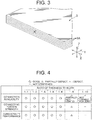
- the conductor 3 consists of metal having a conductivity. As shown in Fig.3 , the conductor 3 includes six (a plurality of) thin plates 3A which are stacked (it may be a bus bar). Further, the conductor 3 has a plate shape with a width b (arrow X) which is larger than its height a (thickness, arrow Z) by a factor of 8, as shown in Fig.2(B) . It is to be noted that in Fig.2(B) , the thin plates 3A are omitted from the conductor 3, and a general shape of the conductor 3 is shown conceptually.
- the end face 30 to be connected to the bundle of cores 22 extends in the ZX-plane orthogonal to the forward-backward direction (arrow Y) so that the end face 30 is opposed to the tip end faces 20 of the bundle of cores 22, as shown in Fig.2(B) .
- the end face 30 of the conductor 3 has a plate shape with a rectangular cross section, having a width b (arrow X) which is larger than its height a (arrow Z) by a factor of 8, as shown in Fig.2(B) .
- the conductor 3 according to the present embodiment consists of a plurality of thin plates 3A, it is to be noted that the conductor 3 may consist of a single metal sheet (bus bar).
- Such an electric wire 1 with the conductor is assembled according to the following procedure.
- the coating section 23 is stripped off at the front end portion 2f of the electric wire 2 to expose the multiple strands 21, as shown in Fig.1 .
- the strands 21 are jointed via ultrasound, wherein the strands 21 are configured in a plate shape having a rectangular cross section and a width b (arrow X), wherein the width b is larger than the height a (arrow Z) by a factor of 8, whereby the bundle of cores 22 is formed.
- the tip end faces 20 of the bundle of cores 22 are formed so as to have a substantially same shape as the end face 30 of the conductor 3.
- the tip end faces 20 of the bundle of cores 22 are butt-connected to the end face 30 of the conductor 3.
- the electric wire 2 is electrically connected to the end face 30 of the conductor 3 to produce the complete electric wire 1 with the conductor.
- the conductor 3 has a plate shape, and it is configured so that the plurality of strands 21 is butt-connected to an end face 30 of the conductor 3, the plurality of strands having a same plate shape as the end face 30 of the conductor 3 in advance.
- This enables the electric wire 2 to be connected to the end face 30 of the conductor 3 by configuring the plurality of strands 21 constituting the electric wire 2 in the same plate shape as the end face 30 of the conductor 3 in advance. This may enable the miniaturization in the height direction.
- the conductor 3 is configured with the plurality of thin plates 3A which are stacked. This enables the conductor 3 to have a desired thickness by varying the number of thin plates 3A.
- Fig.4 shows the results. In Fig.4 , " ⁇ " indicates “good (passed)”, “ ⁇ ” indicates “partially defect (failed)”, “ ⁇ ” indicates “defect (failed)”, and "-" indicates "not confirmed”.
- the tip end faces 20 of the bundle of cores 22 as well as the end face 30 of the conductor 3 have a rectangular shape.
- their shapes are not limited thereto. It may include an elliptical shape with a width (arrow X) being larger than a height (arrow Z).
- the present invention is not limited thereto. Namely, while the present invention is particularly shown and described mainly with regard to the specific embodiments, the above mentioned embodiments may be modified in various manners in shape, material characteristics, amount or other detailed features by those skilled in the art without departing from the scope of the technical idea and purpose of the present invention. Therefore, the description with limited shapes, material characteristics etc. according to the above disclosure is not limiting the present invention, but merely illustrative for easier understanding the present invention so that the description using names of the elements without a part or all of the limitations to their shapes, material characteristics etc. is also included in the present invention.
Landscapes
- Engineering & Computer Science (AREA)
- Mechanical Engineering (AREA)
- Manufacturing & Machinery (AREA)
- Connections Effected By Soldering, Adhesion, Or Permanent Deformation (AREA)
- Non-Insulated Conductors (AREA)
- Insulated Conductors (AREA)
Applications Claiming Priority (1)
| Application Number | Priority Date | Filing Date | Title |
|---|---|---|---|
| JP2020091962A JP2021190210A (ja) | 2020-05-27 | 2020-05-27 | 導体接続構造 |
Publications (1)
| Publication Number | Publication Date |
|---|---|
| EP3916919A1 true EP3916919A1 (de) | 2021-12-01 |
Family
ID=75977648
Family Applications (1)
| Application Number | Title | Priority Date | Filing Date |
|---|---|---|---|
| EP21174335.6A Withdrawn EP3916919A1 (de) | 2020-05-27 | 2021-05-18 | Leiterverbindungsstruktur |
Country Status (4)
| Country | Link |
|---|---|
| US (1) | US20210376494A1 (de) |
| EP (1) | EP3916919A1 (de) |
| JP (1) | JP2021190210A (de) |
| CN (1) | CN113745863A (de) |
Families Citing this family (1)
| Publication number | Priority date | Publication date | Assignee | Title |
|---|---|---|---|---|
| US20250016909A1 (en) | 2021-11-24 | 2025-01-09 | Sumitomo Electric Industries, Ltd. | Printed wiring board |
Citations (7)
| Publication number | Priority date | Publication date | Assignee | Title |
|---|---|---|---|---|
| JPS63250082A (ja) * | 1987-04-06 | 1988-10-17 | 株式会社 井上製作所 | 薄板導体重ね合せ型の可撓性接続端子の製造方法 |
| JPH0679477A (ja) * | 1992-08-27 | 1994-03-22 | Ohara Kk | 溶接機用シャント端子の製造方法 |
| JP2009199788A (ja) * | 2008-02-20 | 2009-09-03 | Inoue Seisakusho:Kk | 可撓性接続端子 |
| DE102013101080B3 (de) * | 2013-02-04 | 2014-04-03 | Connex Gmbh | Verfahren zur Herstellung eines Strombandes |
| JP2014207108A (ja) | 2013-04-11 | 2014-10-30 | 矢崎総業株式会社 | 電線と端子との接合構造 |
| US9666955B2 (en) * | 2014-09-05 | 2017-05-30 | Sumitomo Wiring Systems, Ltd. | Conductive line and routing structure for the same |
| US20180304831A1 (en) * | 2017-04-24 | 2018-10-25 | Yazaki Corporation | Electric wire and wire harness |
Family Cites Families (2)
| Publication number | Priority date | Publication date | Assignee | Title |
|---|---|---|---|---|
| JP3395373B2 (ja) * | 1994-07-14 | 2003-04-14 | 住友電装株式会社 | 電線のスプライス部構造 |
| JP2011014438A (ja) * | 2009-07-03 | 2011-01-20 | Hitachi Cable Ltd | 電線連結構造及びその電線連結構造を有する車両用導電路 |
-
2020
- 2020-05-27 JP JP2020091962A patent/JP2021190210A/ja active Pending
-
2021
- 2021-05-11 US US17/317,134 patent/US20210376494A1/en not_active Abandoned
- 2021-05-18 EP EP21174335.6A patent/EP3916919A1/de not_active Withdrawn
- 2021-05-27 CN CN202110586782.1A patent/CN113745863A/zh not_active Withdrawn
Patent Citations (7)
| Publication number | Priority date | Publication date | Assignee | Title |
|---|---|---|---|---|
| JPS63250082A (ja) * | 1987-04-06 | 1988-10-17 | 株式会社 井上製作所 | 薄板導体重ね合せ型の可撓性接続端子の製造方法 |
| JPH0679477A (ja) * | 1992-08-27 | 1994-03-22 | Ohara Kk | 溶接機用シャント端子の製造方法 |
| JP2009199788A (ja) * | 2008-02-20 | 2009-09-03 | Inoue Seisakusho:Kk | 可撓性接続端子 |
| DE102013101080B3 (de) * | 2013-02-04 | 2014-04-03 | Connex Gmbh | Verfahren zur Herstellung eines Strombandes |
| JP2014207108A (ja) | 2013-04-11 | 2014-10-30 | 矢崎総業株式会社 | 電線と端子との接合構造 |
| US9666955B2 (en) * | 2014-09-05 | 2017-05-30 | Sumitomo Wiring Systems, Ltd. | Conductive line and routing structure for the same |
| US20180304831A1 (en) * | 2017-04-24 | 2018-10-25 | Yazaki Corporation | Electric wire and wire harness |
Also Published As
| Publication number | Publication date |
|---|---|
| CN113745863A (zh) | 2021-12-03 |
| JP2021190210A (ja) | 2021-12-13 |
| US20210376494A1 (en) | 2021-12-02 |
Similar Documents
| Publication | Publication Date | Title |
|---|---|---|
| US10431906B1 (en) | Automotive wiring harness flat cable end termination | |
| EP2808947A1 (de) | Crimpklemme, crimpverbindungsstruktur und verfahren zur herstellung einer crimpverbindungsstruktur | |
| JPS6380492A (ja) | コネクタの結線方法 | |
| EP3916919A1 (de) | Leiterverbindungsstruktur | |
| CN100394514C (zh) | 扁形电缆 | |
| US8272901B2 (en) | Crimp contacts and electrical connector assemblies including the same | |
| KR102338051B1 (ko) | 동축 커넥터 및 동축 케이블을 구비한 동축 커넥터 | |
| JP5390792B2 (ja) | 接続部材 | |
| EP3916920B1 (de) | Anschlussstruktur | |
| JP2009037748A (ja) | ケーブルコネクタ及びケーブル接続方法 | |
| JP2001068244A (ja) | ケーブル導体の通電溶接方法及び接続コネクタ | |
| US6241549B1 (en) | Pressure-contact terminal and electric connection box containing pressure-contact terminals | |
| WO2017115710A1 (ja) | 端子付電線の製造方法及び端子付電線 | |
| CN104347992A (zh) | 压接连接器、带电线的压接连接器、以及压接连接器与包覆电线的连接方法 | |
| CN101841100B (zh) | 带敛缝外壳的电连接器和屏蔽电缆束 | |
| CN1747076B (zh) | 扁平电缆 | |
| CN115117647A (zh) | 带端子的电线 | |
| JP2026057921A (ja) | 導体接続構造 | |
| US12525732B2 (en) | Electrical cable or electrical line configured with a plug-in contour for plugging directly into a mating plug | |
| CN102437447B (zh) | 压接接触器及包括该压接接触器的电连接器组件 | |
| JP4807796B2 (ja) | ケーブルコネクタ及びケーブル接続方法 | |
| JPH0817546A (ja) | フラットケーブル用コネクタの組立方法 | |
| JP2018022642A (ja) | 端子圧着電線の製造方法 | |
| JP2026007125A (ja) | 導体接続構造及びその製造方法 | |
| WO2014129605A1 (ja) | 接続構造体の製造方法、接続構造体、及び圧着装置 |
Legal Events
| Date | Code | Title | Description |
|---|---|---|---|
| PUAI | Public reference made under article 153(3) epc to a published international application that has entered the european phase |
Free format text: ORIGINAL CODE: 0009012 |
|
| STAA | Information on the status of an ep patent application or granted ep patent |
Free format text: STATUS: REQUEST FOR EXAMINATION WAS MADE |
|
| 17P | Request for examination filed |
Effective date: 20210518 |
|
| AK | Designated contracting states |
Kind code of ref document: A1 Designated state(s): AL AT BE BG CH CY CZ DE DK EE ES FI FR GB GR HR HU IE IS IT LI LT LU LV MC MK MT NL NO PL PT RO RS SE SI SK SM TR |
|
| B565 | Issuance of search results under rule 164(2) epc |
Effective date: 20211022 |
|
| STAA | Information on the status of an ep patent application or granted ep patent |
Free format text: STATUS: EXAMINATION IS IN PROGRESS |
|
| 17Q | First examination report despatched |
Effective date: 20220126 |
|
| STAA | Information on the status of an ep patent application or granted ep patent |
Free format text: STATUS: THE APPLICATION IS DEEMED TO BE WITHDRAWN |
|
| 18D | Application deemed to be withdrawn |
Effective date: 20230404 |