EP3916962A1 - Permanentmagnetmotor mit feldschwächungsanordnung - Google Patents
Permanentmagnetmotor mit feldschwächungsanordnung Download PDFInfo
- Publication number
- EP3916962A1 EP3916962A1 EP20176838.9A EP20176838A EP3916962A1 EP 3916962 A1 EP3916962 A1 EP 3916962A1 EP 20176838 A EP20176838 A EP 20176838A EP 3916962 A1 EP3916962 A1 EP 3916962A1
- Authority
- EP
- European Patent Office
- Prior art keywords
- permanent magnet
- motor
- field weakening
- arrangement
- rotor
- Prior art date
- Legal status (The legal status is an assumption and is not a legal conclusion. Google has not performed a legal analysis and makes no representation as to the accuracy of the status listed.)
- Pending
Links
Images



Classifications
-
- H—ELECTRICITY
- H02—GENERATION; CONVERSION OR DISTRIBUTION OF ELECTRIC POWER
- H02K—DYNAMO-ELECTRIC MACHINES
- H02K1/00—Details of the magnetic circuit
- H02K1/06—Details of the magnetic circuit characterised by the shape, form or construction
- H02K1/22—Rotating parts of the magnetic circuit
- H02K1/27—Rotor cores with permanent magnets
- H02K1/2706—Inner rotors
- H02K1/272—Inner rotors the magnetisation axis of the magnets being perpendicular to the rotor axis
- H02K1/274—Inner rotors the magnetisation axis of the magnets being perpendicular to the rotor axis the rotor consisting of two or more circumferentially positioned magnets
- H02K1/2753—Inner rotors the magnetisation axis of the magnets being perpendicular to the rotor axis the rotor consisting of two or more circumferentially positioned magnets the rotor consisting of magnets or groups of magnets arranged with alternating polarity
- H02K1/276—Magnets embedded in the magnetic core, e.g. interior permanent magnets [IPM]
-
- H—ELECTRICITY
- H02—GENERATION; CONVERSION OR DISTRIBUTION OF ELECTRIC POWER
- H02K—DYNAMO-ELECTRIC MACHINES
- H02K1/00—Details of the magnetic circuit
- H02K1/02—Details of the magnetic circuit characterised by the magnetic material
-
- H—ELECTRICITY
- H02—GENERATION; CONVERSION OR DISTRIBUTION OF ELECTRIC POWER
- H02K—DYNAMO-ELECTRIC MACHINES
- H02K1/00—Details of the magnetic circuit
- H02K1/06—Details of the magnetic circuit characterised by the shape, form or construction
- H02K1/22—Rotating parts of the magnetic circuit
- H02K1/27—Rotor cores with permanent magnets
- H02K1/2706—Inner rotors
- H02K1/272—Inner rotors the magnetisation axis of the magnets being perpendicular to the rotor axis
- H02K1/274—Inner rotors the magnetisation axis of the magnets being perpendicular to the rotor axis the rotor consisting of two or more circumferentially positioned magnets
- H02K1/2753—Inner rotors the magnetisation axis of the magnets being perpendicular to the rotor axis the rotor consisting of two or more circumferentially positioned magnets the rotor consisting of magnets or groups of magnets arranged with alternating polarity
- H02K1/276—Magnets embedded in the magnetic core, e.g. interior permanent magnets [IPM]
- H02K1/2766—Magnets embedded in the magnetic core, e.g. interior permanent magnets [IPM] having a flux concentration effect
-
- H—ELECTRICITY
- H02—GENERATION; CONVERSION OR DISTRIBUTION OF ELECTRIC POWER
- H02K—DYNAMO-ELECTRIC MACHINES
- H02K21/00—Synchronous motors having permanent magnets; Synchronous generators having permanent magnets
- H02K21/02—Details
- H02K21/021—Means for mechanical adjustment of the excitation flux
-
- H—ELECTRICITY
- H02—GENERATION; CONVERSION OR DISTRIBUTION OF ELECTRIC POWER
- H02K—DYNAMO-ELECTRIC MACHINES
- H02K21/00—Synchronous motors having permanent magnets; Synchronous generators having permanent magnets
- H02K21/02—Details
- H02K21/021—Means for mechanical adjustment of the excitation flux
- H02K21/028—Means for mechanical adjustment of the excitation flux by modifying the magnetic circuit within the field or the armature, e.g. by using shunts, by adjusting the magnets position, by vectorial combination of field or armature sections
-
- H—ELECTRICITY
- H02—GENERATION; CONVERSION OR DISTRIBUTION OF ELECTRIC POWER
- H02K—DYNAMO-ELECTRIC MACHINES
- H02K21/00—Synchronous motors having permanent magnets; Synchronous generators having permanent magnets
- H02K21/12—Synchronous motors having permanent magnets; Synchronous generators having permanent magnets with stationary armatures and rotating magnets
- H02K21/14—Synchronous motors having permanent magnets; Synchronous generators having permanent magnets with stationary armatures and rotating magnets with magnets rotating within the armatures
-
- H—ELECTRICITY
- H02—GENERATION; CONVERSION OR DISTRIBUTION OF ELECTRIC POWER
- H02K—DYNAMO-ELECTRIC MACHINES
- H02K21/00—Synchronous motors having permanent magnets; Synchronous generators having permanent magnets
- H02K21/12—Synchronous motors having permanent magnets; Synchronous generators having permanent magnets with stationary armatures and rotating magnets
- H02K21/24—Synchronous motors having permanent magnets; Synchronous generators having permanent magnets with stationary armatures and rotating magnets with magnets axially facing the armatures, e.g. hub-type cycle dynamos
-
- H—ELECTRICITY
- H02—GENERATION; CONVERSION OR DISTRIBUTION OF ELECTRIC POWER
- H02K—DYNAMO-ELECTRIC MACHINES
- H02K2213/00—Specific aspects, not otherwise provided for and not covered by codes H02K2201/00 - H02K2211/00
- H02K2213/09—Machines characterised by the presence of elements which are subject to variation, e.g. adjustable bearings, reconfigurable windings, variable pitch ventilators
Definitions
- the present invention relates to a permanent magnet motor, as well as a rotor for a permanent magnet motor and a field weakening mechanical arrangement for such a rotor.
- the speed of the motor can be increased by a technique, called field weakening.
- field weakening When the field of the motor is weakened, the back-emf reduces, so a larger current flows through the armature winding and this increases the speed of the motor.
- field weakening extends the operation range of the motor into a constant power-flux weakening regime. Consequently, the drive torque-speed operating range of the motor is increased.
- field weakening is carried out by using stator current components to counter the fixed amplitude magnetic airgap flux generated by the rotor magnets.
- a permanent magnet motor comprising a stator, configured for generating a time-varying magnetic field, and a rotor, being arranged inside of the stator, comprises at least one permanent magnet that provides a constant magnetic field.
- the permanent magnet is made of a flexible material.
- the stator is configured for rotating the rotor by taking along the constant magnetic field of the rotor with the time-varying magnetic field of the stator.
- the rotor comprises a field weakening mechanical arrangement configured for weakening a flux of the permanent magnet motor.
- the permanent magnet can be deformed by the centrifugal force of the rotation of the rotor in a 3D-motion. This allows a more precise tailoring of the field weakening for the motor, leading to an improved rotational speed, as well as decreased electromagnetic losses
- the permanent magnet to be deformed relates to a property of the permanent magnet that allows the permanent magnet to change its shape.
- an external force preferably the centrifugal force, causes the change of the shape of the permanent magnet.
- the field weakening mechanical arrangement is configured for allowing the permanent magnet to be deformed based on a magnitude of the centrifugal force provided by the rotation of the rotor.
- the rotor is disposed radially inside of the stator.
- a volumetric temperature distribution in the motor is not homogenous. Namely, as the convection cooled end windings in a permanent magnet synchronous motor is warmer than conduction cooled mid axial section of the stator, the magnets in the rotor will also be warmer at the end regions. Hence, the permanent magnets will endure different temperatures depending on their axial position. Therefore, they will induce different magnetic fluxes depending on their axial position in the rotor. By deforming the permanent magnets, more field weakening at a desired axial section of the rotor is provided.
- the centrifugal force working on the at least one permanent magnet in the centrifugal force direction also increases. Consequently, with an increasing rotational speed of the rotor, the deformable permanent magnet tries to deform in the centrifugal force direction.
- the recess of the field weakening mechanical arrangement allows the permanent magnet a tailored deformation based on the centrifugal force.
- the permanent magnet motor is a permanent magnet synchronous motor.
- an extension of the invention to other electric motor types is possible.
- the change of shape of the permanent magnet is directed in a centrifugal force direction. Further preferably, the change of shape of the permanent magnet is allowed in a direction that leads to a highest motor efficiency through field weakening.
- the permanent magnet in particular the deformation of the permanent magnet, is passively controlled.
- at least one permanent magnet is aligned itself, in particular its poles, in an advantageous fashion due to the centrifugal force provided by the rotation of the rotor.
- the field weakening arrangement is tailored to the properties of the motor.
- a shape of the recess is predetermined, or in other words tailored, to the properties of the motor.
- the permanent magnet automatically positions itself due to the centrifugal force of the rotation of the motor. Consequently, a complex actuator based active control of the field weakening arrangement can be omitted.
- the shape of the recess and thus the field weakening arrangement is configured for allowing the permanent magnet a predetermined degree of freedom for deformation.
- the recess allows the permanent magnet to be only partially deformable.
- the deformation of the permanent magnet being a torsion in a torsional direction.
- the field weakening mechanical arrangement is configured for allowing only a mid section of the permanent magnet to be deformed by the centrifugal force in the centrifugal force direction.
- the field weakening mechanical arrangement is configured for only at least one end section of the permanent magnet to be deformed by the centrifugal force.
- the flexible material, the permanent magnet is made of preferably comprises Aluminum and Ferrite.
- Aluminum has a Youngs' Modulus of 69 and Ferrite has a Young's Modulus of 4-5.5.
- a permanent magnet that allows for relatively small shape changes in three dimensions can be designed.
- different material compounds or alloys with different Youngs' Modulus may be designed, in particular based on the expected rotational speed of the rotor and the needed flexibility of the permanent magnet.
- the field weakening mechanical arrangement allows a mechanical field weakening effect, or in other words field weakening feature, easily being tailored for the motor.
- the permanent magnet automatically deforms based on the applied centrifugal force, wherein no complex active control is necessary.
- a shape of the recess of the permanent magnet is dependent on desired field weakening properties of the field weakening mechanical arrangement.
- the shape of the recess confining the permanent magnet is predetermined when manufacturing the field weakening mechanical arrangement.
- a control logic may be added to take into account aging and fouling of the electric motor in use. Further preferably, servicing to update needed field weakening per individual application by changing recess contours may be included.
- the desired field weakening properties describe how much the field of the motor is desired to be weakened depending on the rotational speed of the rotor. Based on the desired field weakening properties of the field weakening mechanical arrangement, the field weakening mechanical arrangement is designed, or in other words tailored.
- the shape of the recess is configured accordingly to allow the permanent magnet a deformation, in particular in the centrifugal force direction, which is the direction, the centrifugal force works when the rotor is rotating.
- the shape of the recess preferably defines a type of deformation, the permanent magnet is allowed to do, for example a torsion around an axis of the permanent magnet or bending the permanent magnet, to tune the magnet pole vector orientation.
- the shape of the recess preferably is configured to allow only parts of the permanent magnet to deform.
- the field weakening mechanical arrangement allows a mechanical field weakening effect, for the motor easily being tailored to the motor.
- a flexibility of the permanent magnet is dependent on desired field weakening properties of the field weakening mechanical arrangement.
- the flexibility of the permanent magnet is predetermined when manufacturing the permanent magnet.
- the flexibility of the permanent magnet is determined by the type of material used to manufacture the permanent magnet. The more flexible the permanent magnet is, the earlier the permanent magnet will deform, when a centrifugal force is applied to the permanent magnet.
- the field weakening mechanical arrangement allows a mechanical field weakening effect, for the motor easily being tailored to the motor.
- the field weakening properties of the field weakening arrangement are dependent on an expected motor temperature and/or an expected rotational speed of the motor.
- the expected motor temperature preferably comprises an expected temperature of the rotor and further comprises an expected temperature of the permanent magnet during operation of the motor.
- the expected rotational speed of the motor comprises a range of rotational speed of the motor during operation, in particular a maximum rotational speed of the motor.
- the field weakening mechanical arrangement allows a mechanical field weakening effect, for the motor easily being tailored to the motor.
- the permanent magnet comprises a plurality of permanent magnet units surrounded by a flexible coating layer.
- the permanent magnet units and the flexible coating layer define a permanent magnet doped in a flexible compound material.
- the permanent magnet units preferably are a plurality of permanent magnets, smaller than the overall permanent magnet with a prescribed collective pole vector. Together with the flexible coating layer, the permanent magnet units preferably constitute the integral permanent magnet.
- the plurality of permanent magnet units is embedded within the flexible coating layer.
- the permanent magnet preferably, comprises a flexible portion, in particular the flexible coating layer, and a non flexible portion, in particular the permanent magnet units.
- the coating layer preferably is made of a flexible non-magnetic material, like rubber, an inflatable cushion or a memory alloy, which chances its shape at a pre-set temperature. Embedding the permanent magnet units, which are made of a magnet material, in a flexible coating layer allows the permanent magnet units to be non-flexible. Thus, even when using a non-flexible magnetic material for the permanent magnet, the flexible coating layer still provides the necessary flexibility of the permanent magnet.
- the flexible coating layer deforms into the recess of the field weakening mechanical arrangement, taking with it the non-flexible permanent magnet units.
- the non-flexible permanent magnet units change their position within the field weakening mechanical arrangement based on the centrifugal force applied to the permanent magnet.
- the permanent magnet units are also made of a flexible material, preferably of a material less flexible than the material of the coating layer.
- the permanent magnet comprises a plurality of permanent magnet units, a first flexible support layer and a second flexible support layer, wherein the plurality of permanent magnet units are distributed between the first flexible support layer and the second flexible support layer.
- the permanent magnet comprises a flexible portion and a non-flexible portion.
- the flexible portion comprises the first flexible support layer and the second flexible support layer.
- the permanent magnet units are sandwiched between the first flexible support layer and the second flexible support layer.
- the first flexible support layer and the second flexible support layer are preferably made of a flexible non-magnetic material, like rubber or an inflatable cushion.
- the first flexible support layer and second flexible support layer are disposed parallel to each other.
- the thickness of the first flexible support layer and the second flexible support layer allows a tailored protection of the permanent magnet units from heat exposure.
- the at least one permanent magnet comprises a length direction along a length of the at least one permanent magnet and a width direction along a width of the at least one permanent magnet; and the deformation of the permanent magnet being a torsion around the length direction of the permanent magnet.
- the length of the permanent magnet is defined by a longer side of the permanent magnet, wherein the width of the permanent magnet is defined by a shorter side of the permanent magnet.
- the deformation in form of a torsion allows distributing the field weakening effect more uniformly in the geometry of the motor, in particular in view of a simple being of the ends of the permanent magnet.
- the at least one permanent magnet is arranged inside the rotor.
- Integrating the at least one permanent magnet inside the rotor provides a higher flux weakening capability of the motor.
- the field weakening mechanical arrangement is configured for allowing the permanent magnet to change a position of the permanent magnet by the centrifugal force provided by the rotation of the rotor.
- the field weakening arrangement is configured for allowing the permanent magnet to change the position of the permanent magnet based on a magnitude of the centrifugal force provided by the rotation of the rotor.
- the at least one permanent magnet comprises a length direction along a length of the at least one permanent magnet and a width direction along a width of the at least one permanent magnet; and the mechanical arrangement being configured for allowing the at least one permanent magnet a rotational motion around an end of the at least one permanent magnet in the length direction.
- the mechanical arrangement is configured for allowing the at least one permanent magnet a motion along the length direction of the at least one permanent magnet.
- the field weakening mechanical arrangement comprises a rail arrangement for guiding the at least one permanent magnet within the field weakening mechanical arrangement.
- the rail arrangement defines a possible movement path of the permanent magnet within the field weakening mechanical arrangement. This applies to a movement of the permanent magnet as well as a deformation of the permanent magnet.
- the field weakening can advantageously be distributed in the motor, as dictated by temperature gradients.
- the field weakening mechanical arrangement comprises a positioning arrangement for positioning the at least one permanent magnet in a desired position.
- the positioning arrangement comprises an inflatable cushion, being controlled by a gas bladder, or a damping system for allowing a motion path for the permanent magnet.
- the positioning arrangement comprises a return arrangement for returning the permanent magnet in its original position for lower RPM.
- the return arrangement comprises a spring arrangement.
- the spring arrangement is preferably disposed at a middle portion of the permanent magnet. Additional springs with different stiffness can be distributed along the magnet for a 3D flexure.
- the positioning of the permanent magnet is overridden by the centrifugal force at a certain rotational speed of the rotor.
- the positioning arrangement is an inflatable cushion
- the positioning effect of the cushion will be overridden if the centrifugal force exceeds a magnitude of a positioning force that positions the permanent magnet due to the positioning arrangement.
- a characteristics of the positioning arrangement is predetermined dependent on an application temperature and/or a rotational speed of the motor.
- the characteristics of the positioning arrangement is tailored to the application of the motor.
- a rotor for a permanent magnet motor as described herein, is provided.
- the rotor which is arranged inside of a stator, comprises at least one permanent magnet that provides a constant magnetic field, the permanent magnet being made of a flexible material.
- the rotor preferably comprises a field weakening mechanical arrangement configured for weakening a flux of the permanent magnet motor.
- the field weakening mechanical arrangement supports the permanent magnet and is configured for allowing the permanent magnet to be deformed by the centrifugal force provided by the rotation of the rotor.
- a field weakening mechanical arrangement for a rotor as described herein, is provided.
- the field weakening mechanical arrangement is disposed in a rotor of a permanent magnet motor and supports a permanent magnet and is configured for allowing the permanent magnet to be deformed by a magnitude of centrifugal force provided by the rotation of the rotor.
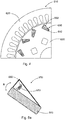
- Fig. 1 shows a schematic view of a permanent magnet motor 10, in this case a permanent magnet synchronous motor, according to a first embodiment.
- the permanent magnet motor 10 comprises a stator 20 and a rotor 30.
- the stator 20 is configured for generating a time-varying magnetic field, in particular by using at least one electromagnet.
- the stator 20 has a circular shape.
- the rotor 30 also has a circular shape and is disposed radially inside of the stator 20.
- the rotor 30 comprises at least one, in this case a plurality of, permanent magnets 40.
- the permanent magnets 40 are providing a constant magnetic field.
- the electromagnets of the stator 20 are operated in such a way that the rotor 30 is rotated within the stator 20.
- the time-varying magnetic field of the electromagnets of the stator 20 carry along the constant magnetic field of the permanent magnets of the rotor 20.
- field weakening features are used.
- the permanent magnets 40 are embedded within the rotor 30.
- the rotor 30 comprises a field weakening arrangement 50 supporting the at least one permanent magnet 40.
- each permanent magnet 40 is supported by one field weakening arrangement 50.
- the field weakening arrangement 50 in its most basic form, is formed by a cavity in the rotor 30. The cavity however is of a larger volume than the volume of the permanent magnet 40. Thus, a recess 60 remains that is not occupied by the permanent magnet 40, when the motor stands still.
- the permanent magnets 40 are made of a flexible material, for example an aluminum ferrite alloy.
- a centrifugal force is spontaneously imposed on to the permanent magnets 40 in a centrifugal force direction, or in other words, a radially outwards direction.
- the recesses 60 of the field weakening arrangements 50 are disposed in such a way, that the permanent magnets 40 are deformed in the centrifugal force direction by the centrifugal force.
- at least parts of the permanent magnets 40 are moved radially outwards, dependent on the rotational speed of the rotor 30. This leads to a field weakening effect. Consequently, the rotation of the rotor 30 automatically leads to the field weakening effect.
- Fig. 2a shows a schematic view of a deformable permanent magnet 140 according to a first embodiment.
- the permanent magnet 140 has a generally cuboid shape.
- the permanent magnet 140 as shown, is deformable in a torsional direction T in a central portion of the permanent magnet 140 only. This deformation of only a central portion of the permanent magnet 140 is either achieved by the composition of flexible materials or by the space, a recess of a field weakening arrangement in the rotor provides.
- the permanent magnet 140 when the rotor is standing still, the permanent magnet 140 has a non deformed cuboid shape, while an increasing rotational speed of the rotor leads to a deformation of the permanent magnet 140 in the torsional direction T.
- Fig. 2b shows a schematic view of a deformable permanent magnet 240 according to a second embodiment.
- the permanent magnet 240 according to the second embodiment is deformable in a torsional direction T at an end portion of the permanent magnet 240 only.
- the manner and amount of deformation of the permanent magnet 240 is tailored to the application of the permanent magnet motor, the permanent magnet 240 is used in.
- Fig. 3a shows a schematic view of a field weakening arrangement 350 according to a first embodiment.
- the field weakening arrangement 350 comprises a permanent magnet 340 and a recess 360.
- the permanent magnet 340 is completely made of a magnetic and flexible material. Thus, due to a centrifugal force applied to the permanent magnet 340, the permanent magnet 340 deforms into the recess 360 in a centrifugal force direction.
- Fig. 3b shows a schematic view of a field weakening arrangement 450 according to a second embodiment.
- the field weakening arrangement 450 of the second embodiment comprises a permanent magnet 440 and a recess 460.
- the permanent magnet 440 comprises a plurality of permanent magnet units 441 and a coating layer 442.
- the coating layer 442 is embedding the permanent magnet unit 441.
- the permanent magnet units 441 are made of a non-flexible magnetic material. In other words, the permanent magnet units 441 are permanent magnets, which are smaller than the permanent magnet 440.
- the permanent magnet units 441 are preferably arranged distant to each other in a line along the permanent magnet 440.
- the coating layer 442 is made of a flexible material.
- the coating layer 442 is generally made of a non-magnetic flexible material like rubber or an inflatable cushion, the coating layer 442 may also be made of a magnetic flexible material as long as the material fulfills the flexibility requirements of the specific application.
- the coating layer 442 is deformed into the recess 460 and carries the embedded permanent magnet units 441 with it, providing the field weakening feature.
- Fig. 3c shows a schematic view of a field weakening arrangement 550 according to a third embodiment.
- the field weakening arrangement 550 according to the third embodiment comprises a permanent magnet 540 and a recess 560.
- the permanent magnet 540 comprises a plurality of permanent magnet units 541 and a first support layer 542 and a second support layer 543.
- the first support layer 542 and the second support layer 543 are disposed parallel to each other.
- the plurality of permanent magnet units 541 are disposed between the first support layer 542 and the second support layer 543.
- the permanent magnet units 541 are made of a non-flexible magnetic material.
- the first support layer 542 and the second support layer 543 are made of a flexible non-magnetic material.
- Fig. 3d shows a schematic view of the field weakening arrangement 550 of the third embodiment, when a centrifugal force is applied.
- the centrifugal force is applied to the permanent magnet 540, the first support layer 542 and the second support layer 543 are deformed into the recess 560 and carry the embedded permanent magnet units 541 with it, providing the field weakening feature.
- Fig. 4 shows a schematic view of a permanent magnet motor 610 according to a second embodiment.
- the permanent magnet motor 610 of the second embodiment similar to the permanent magnet motor 10 of the first embodiment comprises a stator 620 and a rotor 630.
- the rotor 630 comprises a plurality of permanent magnets 40, each supported by a field weakening arrangement 650.
- the field weakening arrangement 650 provides a possible movement of permanent magnets 40 further described in the following figures.
- Fig. 5a shows a schematic view of a field weakening arrangement 650 according to a fifth embodiment.
- the field weakening arrangement 650 of the fifth embodiment comprises a permanent magnet 640 and a recess 660.
- the field weakening arrangement 650 comprises a positioning arrangement in form of a spring 670.
- the spring 670 holds the permanent magnet 640 in place.
- the movement direction R in this case is a pivot direction.
- the spring 670 returns the permanent magnet 640 back into its original position, when not more centrifugal force is present.
- the spring 670 can be tailored to the specifics of the application of the motor. In other words, stiffness of the spring 670 can be tailored to the application of the motor.
- Fig. 5b shows a schematic view of a field weakening arrangement 750 according to a sixth embodiment.
- the field weakening arrangement 750 of the sixth embodiment comprises a permanent magnet 740 and a recess 760. Further, the field weakening arrangement 750 comprises a positioning arrangement in form of a spring 770. Compared to the embodiment described above, the recess 760 is formed along a length direction of the permanent magnet 740. Consequently, a movement direction R also is along the length direction of the permanent magnet.
- Fig. 5c shows a schematic view of a field weakening arrangement 850 according to a seventh embodiment.
- the field weakening arrangement 850 of the seventh embodiment comprises a permanent magnet 840 and a recess 860. Further, the field weakening arrangement 850 comprises a positioning arrangement in form of an inflatable cushion supplied by a gas bladder 880. Compared to the embodiment described above, the type of positioning arrangement has changed.
- the inflatable cushion 870 with the gas bladder 880 provides similar mechanical features as the spring 770.
- a computer program may be stored/distributed on a suitable medium such as an optical storage medium or a solid-state medium supplied together with or as part of other hardware, but may also be distributed in other forms, such as via the Internet or other wired or wireless telecommunication systems. Any reference signs in the claims should not be construed as limiting the scope of the claims.
Landscapes
- Engineering & Computer Science (AREA)
- Power Engineering (AREA)
- Permanent Field Magnets Of Synchronous Machinery (AREA)
- Permanent Magnet Type Synchronous Machine (AREA)
Priority Applications (3)
| Application Number | Priority Date | Filing Date | Title |
|---|---|---|---|
| EP20176838.9A EP3916962A1 (de) | 2020-05-27 | 2020-05-27 | Permanentmagnetmotor mit feldschwächungsanordnung |
| CN202110544575.XA CN113746235B (zh) | 2020-05-27 | 2021-05-19 | 具有磁场弱化构造的永磁电机 |
| US17/330,644 US11689087B2 (en) | 2020-05-27 | 2021-05-26 | Permanent magnet motor with field weakening arrangement |
Applications Claiming Priority (1)
| Application Number | Priority Date | Filing Date | Title |
|---|---|---|---|
| EP20176838.9A EP3916962A1 (de) | 2020-05-27 | 2020-05-27 | Permanentmagnetmotor mit feldschwächungsanordnung |
Publications (1)
| Publication Number | Publication Date |
|---|---|
| EP3916962A1 true EP3916962A1 (de) | 2021-12-01 |
Family
ID=70861336
Family Applications (1)
| Application Number | Title | Priority Date | Filing Date |
|---|---|---|---|
| EP20176838.9A Pending EP3916962A1 (de) | 2020-05-27 | 2020-05-27 | Permanentmagnetmotor mit feldschwächungsanordnung |
Country Status (3)
| Country | Link |
|---|---|
| US (1) | US11689087B2 (de) |
| EP (1) | EP3916962A1 (de) |
| CN (1) | CN113746235B (de) |
Families Citing this family (2)
| Publication number | Priority date | Publication date | Assignee | Title |
|---|---|---|---|---|
| DE102023112743A1 (de) | 2023-05-15 | 2024-11-21 | Schaeffler Technologies AG & Co. KG | Verfahren zur regelung mechanisch feldgeschwächter elektrischer maschinen |
| US12166389B1 (en) * | 2023-06-06 | 2024-12-10 | Schaeffler Technologies AG & Co. KG | Centrifugal magnetic flux adjuster electrical motor |
Citations (4)
| Publication number | Priority date | Publication date | Assignee | Title |
|---|---|---|---|---|
| JP2006136088A (ja) * | 2004-11-04 | 2006-05-25 | Toyota Industries Corp | 電動モータ及び電動圧縮機 |
| CN106664001A (zh) * | 2014-07-03 | 2017-05-10 | 舍弗勒技术股份两合公司 | 具有机械磁场削弱装置和故障保护执行装置的电机 |
| EP3447888A1 (de) * | 2017-08-22 | 2019-02-27 | Continental Automotive GmbH | Rotor für eine elektrische maschine eines fahrzeugs |
| JP2020010486A (ja) * | 2018-07-06 | 2020-01-16 | トヨタ自動車株式会社 | 電動機のロータ |
Family Cites Families (24)
| Publication number | Priority date | Publication date | Assignee | Title |
|---|---|---|---|---|
| US6194802B1 (en) * | 1999-09-08 | 2001-02-27 | Dantam K. Rao | Axial gap motor with radially movable magnets to increase speed capablity |
| JP2001327105A (ja) * | 2000-05-17 | 2001-11-22 | Fujitsu General Ltd | 電動機の回転子およびその製造方法 |
| JP3740353B2 (ja) * | 2000-07-17 | 2006-02-01 | 株式会社東芝 | 永久磁石式リラクタンス型回転電機 |
| EP1599928B1 (de) * | 2003-02-26 | 2013-08-28 | Robert Bosch Gmbh | Elektrische maschine mit einem permanentmagnet |
| TWI249899B (en) * | 2004-02-20 | 2006-02-21 | Delta Electronics Inc | Magnetic-bearing motor and magnetic-bearing thereof |
| CN102170212B (zh) * | 2006-08-23 | 2012-07-18 | 株式会社东芝 | 永久磁铁式旋转电机 |
| FI121291B (fi) * | 2007-12-11 | 2010-09-15 | Abb Oy | Kestomagneettimoduuli ja moduulin käsittävä sähkökoneen roottori |
| JP5198178B2 (ja) * | 2008-08-06 | 2013-05-15 | 株式会社東芝 | 永久磁石式回転電機及び永久磁石電動機ドライブシステム |
| JP5486036B2 (ja) * | 2012-04-11 | 2014-05-07 | ファナック株式会社 | 温度変化に伴う歪みによる不具合を防止するロータ構造を有する電動機及びその製造方法 |
| JP6007593B2 (ja) * | 2012-05-25 | 2016-10-12 | 株式会社ジェイテクト | ロータ及びこれを備えた回転電機、及びロータの製造方法 |
| JP5153955B1 (ja) * | 2012-07-03 | 2013-02-27 | 勝行 上林 | エネルギー変換装置 |
| JP6060621B2 (ja) * | 2012-10-29 | 2017-01-18 | ミツミ電機株式会社 | 発電装置および発電システム |
| CN203219035U (zh) * | 2012-12-10 | 2013-09-25 | 艾默生环境优化技术(苏州)有限公司 | 转子组件和包括该转子组件的永磁体电机 |
| KR101533228B1 (ko) * | 2013-07-31 | 2015-07-06 | 전자부품연구원 | 고정자 및 이를 구비한 스위치드 릴럭턴스 모터 |
| US20150288233A1 (en) * | 2014-04-02 | 2015-10-08 | Samsung Electronics Co., Ltd. | Rotor and motor using the same |
| CN103904855A (zh) * | 2014-04-22 | 2014-07-02 | 哈尔滨工业大学 | 一种具有初始自启动能力的无刷谐波励磁电动机 |
| CN104300713B (zh) * | 2014-10-17 | 2015-08-19 | 珠海格力节能环保制冷技术研究中心有限公司 | 一种电机转子及采用其的永磁同步电机 |
| EP3320605B1 (de) * | 2015-07-09 | 2019-02-27 | Volkswagen Aktiengesellschaft | Elektromaschine mit magnetflussschwächungsvorrichtung |
| US20170126087A1 (en) * | 2015-10-30 | 2017-05-04 | Rod F. Soderberg | Device including material originating from magnetic particles providing structural and magnetic capabilities |
| CN106571704B (zh) * | 2016-10-09 | 2024-04-09 | 武汉凌达压缩机有限公司 | 一种永磁电机转子及永磁电机 |
| CN109274186A (zh) * | 2017-07-17 | 2019-01-25 | 舍弗勒技术股份两合公司 | 永磁同步电机的转子及永磁同步电机 |
| WO2019026979A1 (ja) * | 2017-08-01 | 2019-02-07 | 株式会社デンソー | 回転電機、回転電機駆動システム、磁石、磁石の製造方法、着磁装置、及び磁石ユニット |
| CN111869067B (zh) * | 2018-03-27 | 2023-05-09 | 株式会社电装 | 电动机 |
| DE202018102332U1 (de) * | 2018-04-25 | 2018-05-02 | Ebm-Papst St. Georgen Gmbh & Co. Kg | Rückschlussring und elektrischer Außenläufermotor |
-
2020
- 2020-05-27 EP EP20176838.9A patent/EP3916962A1/de active Pending
-
2021
- 2021-05-19 CN CN202110544575.XA patent/CN113746235B/zh active Active
- 2021-05-26 US US17/330,644 patent/US11689087B2/en active Active
Patent Citations (4)
| Publication number | Priority date | Publication date | Assignee | Title |
|---|---|---|---|---|
| JP2006136088A (ja) * | 2004-11-04 | 2006-05-25 | Toyota Industries Corp | 電動モータ及び電動圧縮機 |
| CN106664001A (zh) * | 2014-07-03 | 2017-05-10 | 舍弗勒技术股份两合公司 | 具有机械磁场削弱装置和故障保护执行装置的电机 |
| EP3447888A1 (de) * | 2017-08-22 | 2019-02-27 | Continental Automotive GmbH | Rotor für eine elektrische maschine eines fahrzeugs |
| JP2020010486A (ja) * | 2018-07-06 | 2020-01-16 | トヨタ自動車株式会社 | 電動機のロータ |
Also Published As
| Publication number | Publication date |
|---|---|
| US20210376705A1 (en) | 2021-12-02 |
| CN113746235A (zh) | 2021-12-03 |
| US11689087B2 (en) | 2023-06-27 |
| CN113746235B (zh) | 2023-12-19 |
Similar Documents
| Publication | Publication Date | Title |
|---|---|---|
| KR102225323B1 (ko) | 전기 기계 | |
| KR102117140B1 (ko) | 축방향 모터의 폴 슈 냉각 갭 | |
| US8710786B1 (en) | High performance actuator motor | |
| US9083225B2 (en) | Rotary electric machine | |
| US11689087B2 (en) | Permanent magnet motor with field weakening arrangement | |
| JP6447662B2 (ja) | 電動機システムおよびそれを備えたターボ圧縮機 | |
| JP2018189358A (ja) | ターボ圧縮機 | |
| US20090001831A1 (en) | Axial Field Electric Motor and Method | |
| US20080074009A1 (en) | Fan system, electric motor, and claw-pole motor | |
| JP2002354767A (ja) | 磁気浮上電動機 | |
| JP2012130223A (ja) | 同期モータ | |
| TW201136107A (en) | Linear motor | |
| WO2020076185A1 (ru) | Электрический мотор | |
| Luo et al. | Design of voice coil motor with the forward winding for linear vibro-impact systems | |
| CN101405929B (zh) | 电动机及驱动控制装置 | |
| JP2009153305A (ja) | ブラシレスモータ | |
| US11936246B2 (en) | Axial flux motor | |
| CN214045383U (zh) | 磁悬浮轴承组件、电机及压缩机 | |
| JP5525416B2 (ja) | リニアアクチュエータ | |
| JP7441860B2 (ja) | 環状軸方向磁束モータ | |
| JP2009136118A (ja) | 同期形リニアモータ | |
| JPWO2018154943A1 (ja) | モータ | |
| JP7328604B1 (ja) | ラジアル磁気軸受、圧縮機、及び冷凍機 | |
| JPH10323012A (ja) | リニアモータ | |
| JP7561669B2 (ja) | 磁気ギアードモータおよび磁気ギアードモータの製造方法 |
Legal Events
| Date | Code | Title | Description |
|---|---|---|---|
| PUAI | Public reference made under article 153(3) epc to a published international application that has entered the european phase |
Free format text: ORIGINAL CODE: 0009012 |
|
| STAA | Information on the status of an ep patent application or granted ep patent |
Free format text: STATUS: REQUEST FOR EXAMINATION WAS MADE |
|
| 17P | Request for examination filed |
Effective date: 20201216 |
|
| AK | Designated contracting states |
Kind code of ref document: A1 Designated state(s): AL AT BE BG CH CY CZ DE DK EE ES FI FR GB GR HR HU IE IS IT LI LT LU LV MC MK MT NL NO PL PT RO RS SE SI SK SM TR |
|
| B565 | Issuance of search results under rule 164(2) epc |
Effective date: 20201106 |
|
| STAA | Information on the status of an ep patent application or granted ep patent |
Free format text: STATUS: EXAMINATION IS IN PROGRESS |
|
| 17Q | First examination report despatched |
Effective date: 20220310 |
|
| REG | Reference to a national code |
Ref country code: DE Ref legal event code: R079 Free format text: PREVIOUS MAIN CLASS: H02K0001270000 Ipc: H02K0001276000 |
|
| GRAP | Despatch of communication of intention to grant a patent |
Free format text: ORIGINAL CODE: EPIDOSNIGR1 |
|
| STAA | Information on the status of an ep patent application or granted ep patent |
Free format text: STATUS: GRANT OF PATENT IS INTENDED |
|
| RIC1 | Information provided on ipc code assigned before grant |
Ipc: H02K 1/276 20220101AFI20260130BHEP Ipc: H02K 21/02 20060101ALI20260130BHEP |
|
| INTG | Intention to grant announced |
Effective date: 20260212 |