EP3916980A1 - Dispositif de conversion - Google Patents
Dispositif de conversion Download PDFInfo
- Publication number
- EP3916980A1 EP3916980A1 EP21170736.9A EP21170736A EP3916980A1 EP 3916980 A1 EP3916980 A1 EP 3916980A1 EP 21170736 A EP21170736 A EP 21170736A EP 3916980 A1 EP3916980 A1 EP 3916980A1
- Authority
- EP
- European Patent Office
- Prior art keywords
- terminal
- conversion device
- converter
- load
- stage converter
- Prior art date
- Legal status (The legal status is an assumption and is not a legal conclusion. Google has not performed a legal analysis and makes no representation as to the accuracy of the status listed.)
- Ceased
Links
Images



Classifications
-
- H—ELECTRICITY
- H02—GENERATION; CONVERSION OR DISTRIBUTION OF ELECTRIC POWER
- H02M—APPARATUS FOR CONVERSION BETWEEN AC AND AC, BETWEEN AC AND DC, OR BETWEEN DC AND DC, AND FOR USE WITH MAINS OR SIMILAR POWER SUPPLY SYSTEMS; CONVERSION OF DC OR AC INPUT POWER INTO SURGE OUTPUT POWER; CONTROL OR REGULATION THEREOF
- H02M7/00—Conversion of AC power input into DC power output; Conversion of DC power input into AC power output
- H02M7/02—Conversion of AC power input into DC power output without possibility of reversal
- H02M7/04—Conversion of AC power input into DC power output without possibility of reversal by static converters
- H02M7/12—Conversion of AC power input into DC power output without possibility of reversal by static converters using discharge tubes with control electrode or semiconductor devices with control electrode
- H02M7/21—Conversion of AC power input into DC power output without possibility of reversal by static converters using discharge tubes with control electrode or semiconductor devices with control electrode using devices of a triode or transistor type requiring continuous application of a control signal
- H02M7/217—Conversion of AC power input into DC power output without possibility of reversal by static converters using discharge tubes with control electrode or semiconductor devices with control electrode using devices of a triode or transistor type requiring continuous application of a control signal using semiconductor devices only
- H02M7/2173—Conversion of AC power input into DC power output without possibility of reversal by static converters using discharge tubes with control electrode or semiconductor devices with control electrode using devices of a triode or transistor type requiring continuous application of a control signal using semiconductor devices only in a biphase or polyphase circuit arrangement
-
- H—ELECTRICITY
- H02—GENERATION; CONVERSION OR DISTRIBUTION OF ELECTRIC POWER
- H02M—APPARATUS FOR CONVERSION BETWEEN AC AND AC, BETWEEN AC AND DC, OR BETWEEN DC AND DC, AND FOR USE WITH MAINS OR SIMILAR POWER SUPPLY SYSTEMS; CONVERSION OF DC OR AC INPUT POWER INTO SURGE OUTPUT POWER; CONTROL OR REGULATION THEREOF
- H02M1/00—Details of apparatus for conversion
- H02M1/12—Arrangements for reducing harmonics from AC input or output
- H02M1/123—Suppression of common mode voltage or current
-
- H—ELECTRICITY
- H02—GENERATION; CONVERSION OR DISTRIBUTION OF ELECTRIC POWER
- H02M—APPARATUS FOR CONVERSION BETWEEN AC AND AC, BETWEEN AC AND DC, OR BETWEEN DC AND DC, AND FOR USE WITH MAINS OR SIMILAR POWER SUPPLY SYSTEMS; CONVERSION OF DC OR AC INPUT POWER INTO SURGE OUTPUT POWER; CONTROL OR REGULATION THEREOF
- H02M1/00—Details of apparatus for conversion
- H02M1/12—Arrangements for reducing harmonics from AC input or output
- H02M1/126—Arrangements for reducing harmonics from AC input or output using passive filters
-
- H—ELECTRICITY
- H02—GENERATION; CONVERSION OR DISTRIBUTION OF ELECTRIC POWER
- H02M—APPARATUS FOR CONVERSION BETWEEN AC AND AC, BETWEEN AC AND DC, OR BETWEEN DC AND DC, AND FOR USE WITH MAINS OR SIMILAR POWER SUPPLY SYSTEMS; CONVERSION OF DC OR AC INPUT POWER INTO SURGE OUTPUT POWER; CONTROL OR REGULATION THEREOF
- H02M3/00—Conversion of DC power input into DC power output
- H02M3/22—Conversion of DC power input into DC power output with intermediate conversion into AC
- H02M3/24—Conversion of DC power input into DC power output with intermediate conversion into AC by static converters
- H02M3/28—Conversion of DC power input into DC power output with intermediate conversion into AC by static converters using discharge tubes with control electrode or semiconductor devices with control electrode to produce the intermediate AC
- H02M3/325—Conversion of DC power input into DC power output with intermediate conversion into AC by static converters using discharge tubes with control electrode or semiconductor devices with control electrode to produce the intermediate AC using devices of a triode or a transistor type requiring continuous application of a control signal
- H02M3/335—Conversion of DC power input into DC power output with intermediate conversion into AC by static converters using discharge tubes with control electrode or semiconductor devices with control electrode to produce the intermediate AC using devices of a triode or a transistor type requiring continuous application of a control signal using semiconductor devices only
- H02M3/33569—Conversion of DC power input into DC power output with intermediate conversion into AC by static converters using discharge tubes with control electrode or semiconductor devices with control electrode to produce the intermediate AC using devices of a triode or a transistor type requiring continuous application of a control signal using semiconductor devices only having several active switching elements
-
- H—ELECTRICITY
- H02—GENERATION; CONVERSION OR DISTRIBUTION OF ELECTRIC POWER
- H02M—APPARATUS FOR CONVERSION BETWEEN AC AND AC, BETWEEN AC AND DC, OR BETWEEN DC AND DC, AND FOR USE WITH MAINS OR SIMILAR POWER SUPPLY SYSTEMS; CONVERSION OF DC OR AC INPUT POWER INTO SURGE OUTPUT POWER; CONTROL OR REGULATION THEREOF
- H02M7/00—Conversion of AC power input into DC power output; Conversion of DC power input into AC power output
- H02M7/02—Conversion of AC power input into DC power output without possibility of reversal
- H02M7/04—Conversion of AC power input into DC power output without possibility of reversal by static converters
- H02M7/06—Conversion of AC power input into DC power output without possibility of reversal by static converters using discharge tubes without control electrode or semiconductor devices without control electrode
- H02M7/08—Conversion of AC power input into DC power output without possibility of reversal by static converters using discharge tubes without control electrode or semiconductor devices without control electrode arranged for operation in parallel
-
- H—ELECTRICITY
- H02—GENERATION; CONVERSION OR DISTRIBUTION OF ELECTRIC POWER
- H02M—APPARATUS FOR CONVERSION BETWEEN AC AND AC, BETWEEN AC AND DC, OR BETWEEN DC AND DC, AND FOR USE WITH MAINS OR SIMILAR POWER SUPPLY SYSTEMS; CONVERSION OF DC OR AC INPUT POWER INTO SURGE OUTPUT POWER; CONTROL OR REGULATION THEREOF
- H02M7/00—Conversion of AC power input into DC power output; Conversion of DC power input into AC power output
- H02M7/02—Conversion of AC power input into DC power output without possibility of reversal
- H02M7/04—Conversion of AC power input into DC power output without possibility of reversal by static converters
- H02M7/12—Conversion of AC power input into DC power output without possibility of reversal by static converters using discharge tubes with control electrode or semiconductor devices with control electrode
- H02M7/21—Conversion of AC power input into DC power output without possibility of reversal by static converters using discharge tubes with control electrode or semiconductor devices with control electrode using devices of a triode or transistor type requiring continuous application of a control signal
- H02M7/217—Conversion of AC power input into DC power output without possibility of reversal by static converters using discharge tubes with control electrode or semiconductor devices with control electrode using devices of a triode or transistor type requiring continuous application of a control signal using semiconductor devices only
- H02M7/219—Conversion of AC power input into DC power output without possibility of reversal by static converters using discharge tubes with control electrode or semiconductor devices with control electrode using devices of a triode or transistor type requiring continuous application of a control signal using semiconductor devices only in a bridge configuration
-
- H—ELECTRICITY
- H02—GENERATION; CONVERSION OR DISTRIBUTION OF ELECTRIC POWER
- H02M—APPARATUS FOR CONVERSION BETWEEN AC AND AC, BETWEEN AC AND DC, OR BETWEEN DC AND DC, AND FOR USE WITH MAINS OR SIMILAR POWER SUPPLY SYSTEMS; CONVERSION OF DC OR AC INPUT POWER INTO SURGE OUTPUT POWER; CONTROL OR REGULATION THEREOF
- H02M7/00—Conversion of AC power input into DC power output; Conversion of DC power input into AC power output
- H02M7/42—Conversion of DC power input into AC power output without possibility of reversal
- H02M7/44—Conversion of DC power input into AC power output without possibility of reversal by static converters
- H02M7/48—Conversion of DC power input into AC power output without possibility of reversal by static converters using discharge tubes with control electrode or semiconductor devices with control electrode
- H02M7/483—Converters with outputs that each can have more than two voltages levels
-
- H—ELECTRICITY
- H02—GENERATION; CONVERSION OR DISTRIBUTION OF ELECTRIC POWER
- H02M—APPARATUS FOR CONVERSION BETWEEN AC AND AC, BETWEEN AC AND DC, OR BETWEEN DC AND DC, AND FOR USE WITH MAINS OR SIMILAR POWER SUPPLY SYSTEMS; CONVERSION OF DC OR AC INPUT POWER INTO SURGE OUTPUT POWER; CONTROL OR REGULATION THEREOF
- H02M7/00—Conversion of AC power input into DC power output; Conversion of DC power input into AC power output
- H02M7/42—Conversion of DC power input into AC power output without possibility of reversal
- H02M7/44—Conversion of DC power input into AC power output without possibility of reversal by static converters
- H02M7/48—Conversion of DC power input into AC power output without possibility of reversal by static converters using discharge tubes with control electrode or semiconductor devices with control electrode
- H02M7/483—Converters with outputs that each can have more than two voltages levels
- H02M7/487—Neutral point clamped inverters
-
- H—ELECTRICITY
- H02—GENERATION; CONVERSION OR DISTRIBUTION OF ELECTRIC POWER
- H02M—APPARATUS FOR CONVERSION BETWEEN AC AND AC, BETWEEN AC AND DC, OR BETWEEN DC AND DC, AND FOR USE WITH MAINS OR SIMILAR POWER SUPPLY SYSTEMS; CONVERSION OF DC OR AC INPUT POWER INTO SURGE OUTPUT POWER; CONTROL OR REGULATION THEREOF
- H02M7/00—Conversion of AC power input into DC power output; Conversion of DC power input into AC power output
- H02M7/42—Conversion of DC power input into AC power output without possibility of reversal
- H02M7/44—Conversion of DC power input into AC power output without possibility of reversal by static converters
- H02M7/48—Conversion of DC power input into AC power output without possibility of reversal by static converters using discharge tubes with control electrode or semiconductor devices with control electrode
- H02M7/493—Conversion of DC power input into AC power output without possibility of reversal by static converters using discharge tubes with control electrode or semiconductor devices with control electrode the static converters being arranged for operation in parallel
-
- B—PERFORMING OPERATIONS; TRANSPORTING
- B60—VEHICLES IN GENERAL
- B60L—PROPULSION OF ELECTRICALLY-PROPELLED VEHICLES; SUPPLYING ELECTRIC POWER FOR AUXILIARY EQUIPMENT OF ELECTRICALLY-PROPELLED VEHICLES; ELECTRODYNAMIC BRAKE SYSTEMS FOR VEHICLES IN GENERAL; MAGNETIC SUSPENSION OR LEVITATION FOR VEHICLES; MONITORING OPERATING VARIABLES OF ELECTRICALLY-PROPELLED VEHICLES; ELECTRIC SAFETY DEVICES FOR ELECTRICALLY-PROPELLED VEHICLES
- B60L2210/00—Converter types
- B60L2210/30—AC to DC converters
-
- H—ELECTRICITY
- H02—GENERATION; CONVERSION OR DISTRIBUTION OF ELECTRIC POWER
- H02M—APPARATUS FOR CONVERSION BETWEEN AC AND AC, BETWEEN AC AND DC, OR BETWEEN DC AND DC, AND FOR USE WITH MAINS OR SIMILAR POWER SUPPLY SYSTEMS; CONVERSION OF DC OR AC INPUT POWER INTO SURGE OUTPUT POWER; CONTROL OR REGULATION THEREOF
- H02M1/00—Details of apparatus for conversion
- H02M1/44—Circuits or arrangements for compensating for electromagnetic interference in converters or inverters
-
- H—ELECTRICITY
- H02—GENERATION; CONVERSION OR DISTRIBUTION OF ELECTRIC POWER
- H02M—APPARATUS FOR CONVERSION BETWEEN AC AND AC, BETWEEN AC AND DC, OR BETWEEN DC AND DC, AND FOR USE WITH MAINS OR SIMILAR POWER SUPPLY SYSTEMS; CONVERSION OF DC OR AC INPUT POWER INTO SURGE OUTPUT POWER; CONTROL OR REGULATION THEREOF
- H02M7/00—Conversion of AC power input into DC power output; Conversion of DC power input into AC power output
- H02M7/02—Conversion of AC power input into DC power output without possibility of reversal
- H02M7/04—Conversion of AC power input into DC power output without possibility of reversal by static converters
- H02M7/12—Conversion of AC power input into DC power output without possibility of reversal by static converters using discharge tubes with control electrode or semiconductor devices with control electrode
- H02M7/21—Conversion of AC power input into DC power output without possibility of reversal by static converters using discharge tubes with control electrode or semiconductor devices with control electrode using devices of a triode or transistor type requiring continuous application of a control signal
- H02M7/217—Conversion of AC power input into DC power output without possibility of reversal by static converters using discharge tubes with control electrode or semiconductor devices with control electrode using devices of a triode or transistor type requiring continuous application of a control signal using semiconductor devices only
-
- Y—GENERAL TAGGING OF NEW TECHNOLOGICAL DEVELOPMENTS; GENERAL TAGGING OF CROSS-SECTIONAL TECHNOLOGIES SPANNING OVER SEVERAL SECTIONS OF THE IPC; TECHNICAL SUBJECTS COVERED BY FORMER USPC CROSS-REFERENCE ART COLLECTIONS [XRACs] AND DIGESTS
- Y02—TECHNOLOGIES OR APPLICATIONS FOR MITIGATION OR ADAPTATION AGAINST CLIMATE CHANGE
- Y02T—CLIMATE CHANGE MITIGATION TECHNOLOGIES RELATED TO TRANSPORTATION
- Y02T10/00—Road transport of goods or passengers
- Y02T10/60—Other road transportation technologies with climate change mitigation effect
- Y02T10/70—Energy storage systems for electromobility, e.g. batteries
-
- Y—GENERAL TAGGING OF NEW TECHNOLOGICAL DEVELOPMENTS; GENERAL TAGGING OF CROSS-SECTIONAL TECHNOLOGIES SPANNING OVER SEVERAL SECTIONS OF THE IPC; TECHNICAL SUBJECTS COVERED BY FORMER USPC CROSS-REFERENCE ART COLLECTIONS [XRACs] AND DIGESTS
- Y02—TECHNOLOGIES OR APPLICATIONS FOR MITIGATION OR ADAPTATION AGAINST CLIMATE CHANGE
- Y02T—CLIMATE CHANGE MITIGATION TECHNOLOGIES RELATED TO TRANSPORTATION
- Y02T10/00—Road transport of goods or passengers
- Y02T10/60—Other road transportation technologies with climate change mitigation effect
- Y02T10/7072—Electromobility specific charging systems or methods for batteries, ultracapacitors, supercapacitors or double-layer capacitors
Definitions
- the present disclosure relates to the technical field of power electronics, in particular, to a conversion device.
- An objective of the present disclosure is to provide a conversion device which reduces a common-mode current of the conversion device at least to some extent.
- a conversion device connected between an Alternating Current (AC) power grid and a load.
- the conversion device includes: an inductor, electrically connected to the AC power grid; a first-stage converter having a first terminal electrically connected to the inductor and a second terminal electrically connected to a bus, and the first-stage converter being configured to output a bus voltage based on an input voltage from the AC power grid; a second-stage converter having a first terminal electrically connected to the bus and a second terminal electrically connected to the load, and the second-stage converter being configured to convert the bus voltage into an output voltage to provide energy to the load; and a filtering network having a first terminal, a second terminal and a third terminal, wherein a first resistance-capacitance circuit is disposed between the first terminal and the third terminal of the filtering network, and a second resistance-capacitance circuit is disposed between the second terminal and the third terminal of the filtering network, the first terminal of the filtering network is electrically connected
- the inductor includes a common-mode and differential-mode integrated inductor and is disposed between the AC power grid and the first-stage converter.
- the inductor includes a differential-mode inductor and a common-mode inductor, the differential-mode inductor is connected between the AC power grid and the first-stage converter, and the common-mode inductor is disposed between the AC power grid and the second terminal of the second-stage converter.
- the first resistance-capacitance circuit includes a first resistor and a fifth capacitor connected in series
- the second resistance-capacitance circuit includes a second resistor and a sixth capacitor connected in series.
- the first-stage converter includes an N-level AC-DC converter which includes a plurality of switching bridge arms, wherein both an upper arm and a lower arm of each of the switching bridge arms of the AC-DC converter include a plurality of semiconductor devices connected in series, and a rated withstand voltage Vsemi of each of the semiconductor devices is greater than or equal to (Vbus ⁇ 6)/((N-1) ⁇ Nseries ⁇ ⁇ ), where Vbus represents the bus voltage, 8 represents bus fluctuation, N represents a number of levels of the first-stage converter, ⁇ represents a voltage derating factor of the semiconductor device and ⁇ 1, Nseries represents a number of semiconductor devices connected in series and N series ⁇ 2.
- the conversion device further includes a controller and a DC circuit breaker, the DC circuit breaker is disposed between the first-stage converter and the second-stage converter and is electrically connected to the controller, and an operation of the DC circuit breaker is controlled based on a control signal sent by the controller.
- the first-stage converter includes any one of the following AC-DC converters: a two-level rectifier, a three-level Vienna rectifier, and a three-level neutral point clamped converter.
- the common-mode current in the conversion device can be reduced.
- Blocks shown in the drawings are functional entities and do not necessarily correspond to physically separate entities. That is, these functional entities can be implemented in software, or implemented in one or more hardware modules or integrated circuits, or implemented in different networks and/or processor devices and/or microcontroller devices.
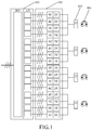
- FIG. 1 shows a topology structure of a conversion device that provides a charging power source 103 for an electric vehicle 104, as shown in FIG. 1 , a Medium-Voltage (MV) transformer 101 is connected to a MV power grid on a primary side, and multiple windings on a secondary side provide a Low-Voltage (LV) AC output.
- the medium-voltage transformer 101 can realize medium voltage isolation, so a power electronic converter 102 on a posterior stage can adopt a non-isolated scheme.
- This scheme has advantages of high full-load efficiency (98%), mature technology and high reliability, but the transformer used therein has a large volume, and in a case of a light load output, it has disadvantages of low efficiency and high harmonic content (Total Harmonic Distortion, THD). For example, under a system power of 2.4MW, if a light load of 100kW is outputted, the efficiency is only 92.5%. In actual applications, there are fewer cases for the full load, and most of the cases it is operated under the light load or the half load.
- a structure of modules 202 is used.
- This scheme has advantages of mature technology and reliability, but since DC bus capacitors of the modules 202 are located in each of single-phase bridge arms, a phase current of each phase flowing through the capacitor of the phase separately will cause power to fluctuate at double frequency. As a result, a large number of capacitors need to be configured to reduce ripple voltages of the capacitors, which will cause a decrease in a power density of the power modules and an increase in the volume of the system.
- a DC power grid combined with new energy and energy storage technologies adapts to rapid development of the data center and the high-power vehicle charging piles, which can achieve local power generation and nearby electricity consumption to reduce cable loss.
- DC will not cause reactive power loss, and there is no issue of reactive power balance and stability, and thus it can improve the system efficiency and the reliability of the power grid operation.
- a basic topology structure of the medium-voltage DC micro-grid includes an AC/DC converter connected to an AC power grid.
- a Pulse Width Modulation (PWM) technology is used, a system common-mode voltage is generated, and the common-mode voltage is superimposed on a differential-mode voltage, which results in an increase in voltages at an AC input terminal and a neutral point of a bus with respect to ground.
- PWM Pulse Width Modulation
- a common-mode current may be generated in the common-mode loop, and if it is not addressed, the common-mode current would cause problems such as insulation, interference, and heat dissipation.
- a higher common-mode current may cause higher loss and lower efficiency of the converter.
- an Alternating Current/Direct Current (AC/DC) converter in the medium-voltage DC micro-grid converts electrical energy of an AC power grid into a DC bus output.
- the medium-voltage AC voltage is ⁇ 1kVAC
- the medium-voltage DC voltage is ⁇ 1.5kVDC.
- the system common-mode voltage generated when the AC/DC converter is operating is superimposed on the differential-mode voltage, which may cause an increase in the voltages at the AC input terminal and the neutral point of the bus with respect to ground, and generate the common-mode current, resulting in higher loss and lower efficiency of the conversion device.
- An exemplary embodiment provides a conversion device to reduce the common-mode current of the conversion device.
- inventions of the present disclosure provide a conversion device connected between an AC grid and a load 301.
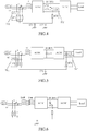
- the conversion device includes: an inductor Lf, electrically connected to the AC power grid; a first-stage converter 302, a first end of the first-stage converter 302 being connected to the inductor Lf, and a second end of the first-stage converter 302 being electrically connected to a DC bus, and first-stage converter 302 being configured to output a bus voltage based on the AC power grid; and a second-stage converter 303, a first end of the second-stage converter 303 being electrically connected to the bus and a second end of the second-stage converter 303 being electrically connected to the load 301, and the second-stage converter 303 being configured to convert the bus voltage into an output voltage to provide energy to the load 301.
- the first resistance-capacitance circuit 701 includes a first resistor R71 and a fifth capacitor C75 connected in series
- the second resistance-capacitance circuit 702 includes a second resistor R72 and a sixth capacitor C76 connected in series.
- the first terminal of the filtering network is a three-phase access terminal
- each of the phases includes the first resistance-capacitance circuit 701.
- One end of the first resistance-capacitance circuits 701 of the three phases respectively corresponds to the three-phase input of the AC power grid, and the other end of the first resistance-capacitance circuits 701 of the three phases is connected to the third terminal of the filtering network.
- the second terminal of the filtering network is a single-phase access terminal, one end of the second resistance-capacitance circuit 702 is connected to the second terminal of the filtering network, and the other end of the second resistance-capacitance circuit 702 is connected to the third terminal of the filtering network.
- the second terminal of the filtering network is electrically connected to the bus end.
- a second capacitor C72 and a third capacitor C73 which are connected in series are connected between the buses, and the second terminal of the filtering network is electrically connected between the second capacitor C72 and the third capacitor C73.
- the system common-mode voltage may be generated, and the common-mode voltage is superimposed on a differential-mode voltage, which will cause an increase in voltages at the AC input terminal and a neutral point of the bus with respect to ground.
- a common-mode current may be generated in the common-mode loop, and if it is not addressed, the common-mode current would cause problems such as insulation, interference, and heat dissipation.
- the filtering network has three terminals, and by disposing the first resistance-capacitance circuit 701 and the second resistance-capacitance circuit 702 in the filtering network, the common-mode current in the conversion device can be reduced.
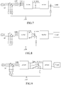
- the inductor can be a common-mode and differential-mode integrated inductor Lf.
- the inductor can include a differential-mode inductor Ldiff and a common-mode inductor Lcm independent from each other.
- the common-mode inductor is used in the filtering network to form a common-mode filtering network.
- the differential-mode inductor Ldiff is connected between the AC power grid and the first-stage converter
- the common-mode inductor Lcm is disposed between the differential-mode inductor and the load.
- the first-stage converter 302 can be an N-level AC-DC converter
- the N-level AC-DC converter includes a plurality of switching bridge arms, both an upper arm and a lower arm of each of the switching bridge arms of the AC-DC converter include a plurality of semiconductor devices connected in series, and a rated withstand voltage value Vsemi of each of the semiconductor devices is greater than or equal to (Vbus ⁇ ⁇ )/((N-1) ⁇ Nseries ⁇ ⁇ ), where Vbus represents the bus voltage, 8 represents bus fluctuation, N represents the number of levels of the first-stage converter, ⁇ represents a voltage derating factor of the semiconductor device and ⁇ 1, Nseries represents the number of semiconductor devices connected in series, and Nseries ⁇ 2.
- the first-stage converter can be a two-level or three-level AC/DC converter, and is not limited thereto.
- the topology structure of the AC/DC converter includes, but is not limited to, a two-level rectifier, a three-level Vienna rectifier, and a three-level neutral point clamped converter.
- each of the upper bridge arm and the lower bridge arm of each of the phases includes two semiconductor devices which are connected in series, that is, power tubes S401.
- the power tubes shown in FIG. 11 are IGBTs, but it is not limited thereto in practical applications.
- the bridge arm of each of the phases of the three-phase three-level Vienna rectifier includes a bidirectional switch composed of one power tube and four diodes, and two upper and lower diodes used for freewheeling.
- the power tube in the bridge arm of each of the phases of the three-phase three-level Vienna rectifier in the prior art is replaced by two power tubes S402 connected in series
- each of the diode in each bridge arm of the three-phase three-level Vienna rectifier in the prior art is replaced by two diodes D401 connected in series.
- the bridge arm of each of the phases of the three-phase three-level neutral point clamped converter includes four power tubes and two diodes.
- the power tubes in the bridge arm of each of the phases of the three-phase three-level neutral point clamped converter in the prior art are replaced by two power tubes S403 connected in series, and each of the diodes in each bridge arm of the three-phase three-level neutral point clamped converter in the prior art are replaced by two diodes D402 connected in series.
- the load can be a DC load
- the second-stage converter can be a DC-DC converter
- the DC-DC converter is electrically connected to the DC load.
- the load can also be an AC load
- the second-stage converter can be a DC-AC converter, and the DC-AC converter is electrically connected to the AC load.
- the DC-DC converter can have multiple topology structures, and a single primary side module of the DC-DC converter can adopt a two-stage or multi-stage topology.
- a single semiconductor device or a structure in which multiple semiconductor devices are connected in series, in parallel or in series-parallel can be used for the semiconductor devices of the DC-DC converter.
- An output mode of an output isolated or non-isolated from the primary side can be used for a secondary side of the DC-DC converter, and connections in parallel, in series or in series-parallel can be used in the secondary side of the DC-DC converter according to the requirements of the load.
- the DC-DC converter of the embodiments of the present disclosure can be a full-bridge LLC DC/DC converter with serial connections in the primary side as shown in FIG. 14 , a DC/DC converter containing a half-bridge LLC circuit with serial connections in the primary side as shown in FIG. 15 , a DC/DC converter containing a three-level half-bridge LLC circuit with serial connections in the primary side as shown in FIG. 16 , a DC/DC bidirectional converter containing a Dual-Active-Bridge (DAB) circuit with serial connections in the primary side as shown in FIG. 17 , or a non-isolated DC/DC bidirectional converter as shown in FIG. 18 .
- DAB Dual-Active-Bridge
- the conversion device further includes a controller (not shown in the figure) which detects power of the load and controls operating states of the at least two AC-DC converters connected in parallel based on the power of the load.
- the conversion device further includes a DC circuit breaker 801 which is disposed between the first-stage converter and the second-stage converter.
- the DC circuit breaker 801 is electrically connected to the controller, and operations of the DC circuit breaker 801 are controlled based on a control signal sent by the controller.
- the new energy entities such as the battery and the photovoltaic panel and the medium-voltage DC bus are connected and disconnected through the DC circuit breaker 801.
- the DC circuit breaker 801 can detect the operating conditions by itself, disconnect a fault point when a fault occurs, and transmit information to the controller.
- the controller performs an overall management based on the uploaded signal.
- the overall management can include setting a fault priority by the controller, for example, the short circuit is in a first priority, and an overcurrent is in a second priority.
- a central control system where the control is located can receive control instructions from a monitoring system to charge and discharge the battery, quickly absorb or release energy by using the energy storage system where the battery is located, smooth voltage fluctuations caused by the photovoltaic grid-connected power generation, improve a balance level of the active power and reactive power of the system, and enhance the stability.
- the energy storage system can be used to improve a dispatchability of photovoltaic power generation, and a charge-discharge control mode can be formulated through an analysis of a distribution of a local power peak and valley time and electricity price to maximize economic benefits with a high throwing and bargain-hunting.
- the first-stage converter can include two or more AC-DC converters connected in parallel.
- the second-stage converter can include two or more DC-DC converters.
- M is a natural number greater than or equal to 2.
- the M DC-DC converters in the second-stage converter are connected in series, where M is a natural number greater than or equal to 2.
- the second-stage converter can also include two or more DC-AC converters, and the two or more DC-AC converters can be connected in parallel or in series.
- the controller controls parts of the at least two AC-DC converters connected in parallel to operate, and controls remaining of the at least two AC-DC converters connected in parallel not to operate.
Landscapes
- Engineering & Computer Science (AREA)
- Power Engineering (AREA)
- Physics & Mathematics (AREA)
- Electromagnetism (AREA)
- Inverter Devices (AREA)
Applications Claiming Priority (1)
| Application Number | Priority Date | Filing Date | Title |
|---|---|---|---|
| CN202010456292.5A CN113726137B (zh) | 2020-05-26 | 2020-05-26 | 变换装置 |
Publications (1)
| Publication Number | Publication Date |
|---|---|
| EP3916980A1 true EP3916980A1 (fr) | 2021-12-01 |
Family
ID=75728590
Family Applications (1)
| Application Number | Title | Priority Date | Filing Date |
|---|---|---|---|
| EP21170736.9A Ceased EP3916980A1 (fr) | 2020-05-26 | 2021-04-27 | Dispositif de conversion |
Country Status (3)
| Country | Link |
|---|---|
| US (2) | US11515806B2 (fr) |
| EP (1) | EP3916980A1 (fr) |
| CN (1) | CN113726137B (fr) |
Cited By (2)
| Publication number | Priority date | Publication date | Assignee | Title |
|---|---|---|---|---|
| DE102022201188A1 (de) | 2022-02-04 | 2023-08-10 | Vitesco Technologies GmbH | Fahrzeugseitige Wechselstrom-Ladeschaltung mit Hochpass-Fehlerschutzimpedanz zwischen Gleichrichter-Sternpunkt und Schutzleiter |
| US20240333170A1 (en) * | 2023-03-29 | 2024-10-03 | Delta Electronics (Shanghai) Co.,Ltd. | Power conversion circuit and power supply device |
Families Citing this family (4)
| Publication number | Priority date | Publication date | Assignee | Title |
|---|---|---|---|---|
| WO2022005206A1 (fr) * | 2020-07-03 | 2022-01-06 | 엘에스일렉트릭(주) | Dispositif de conversion de puissance et son procédé de commande |
| CN114531019B (zh) * | 2022-02-24 | 2024-12-27 | 全球能源互联网研究院有限公司 | 一种振荡抑制电路及供电电源 |
| US12500415B1 (en) * | 2023-11-01 | 2025-12-16 | National Technology & Engineering Solutions Of Sandia, Llc | Solid-state transformer for mitigation of common mode insults |
| CN120810905A (zh) * | 2025-09-10 | 2025-10-17 | 杭州科锐环境能源技术有限公司 | 一种双极膜系统专用不间断电源供配电系统 |
Citations (9)
| Publication number | Priority date | Publication date | Assignee | Title |
|---|---|---|---|---|
| EP0899859A2 (fr) * | 1997-08-23 | 1999-03-03 | Asea Brown Boveri AG | Onduleur avec circuit intermédiaire de tension |
| WO1999049559A2 (fr) * | 1998-03-20 | 1999-09-30 | Lutz Erhartt | Procede et dispositif pour supprimer les parasites dans des changeurs de frequence |
| US20030218838A1 (en) * | 2002-05-22 | 2003-11-27 | Danfoss Drives A/S | Motor controller incorporating an electronic circuit for protection against inrush currents |
| JP2007236137A (ja) * | 2006-03-02 | 2007-09-13 | Fuji Electric Holdings Co Ltd | ノイズフィルタ |
| CN103311944A (zh) * | 2013-05-16 | 2013-09-18 | 国家电网公司 | 一种采用模块化结构的统一潮流控制器及其启动方法 |
| CN103384114A (zh) * | 2013-07-29 | 2013-11-06 | 中国北车集团大连机车研究所有限公司 | Dc600v列车供电装置控制单元的供电电源 |
| US20150103570A1 (en) * | 2012-03-22 | 2015-04-16 | Sew-Eurodrive Gmbh & Co. Kg | Circuit Configuration and System of Capacitors |
| US20180041110A1 (en) * | 2016-08-05 | 2018-02-08 | Delta Electronics (Shanghai) Co.,Ltd. | Power conversion system and method for suppressing the common-mode voltage thereof |
| CN110379625A (zh) * | 2019-07-03 | 2019-10-25 | 西安西电电力电容器有限责任公司 | 应用在矿热炉中防止外壳击穿的电容器 |
Family Cites Families (47)
| Publication number | Priority date | Publication date | Assignee | Title |
|---|---|---|---|---|
| JP3229897B2 (ja) * | 1992-04-13 | 2001-11-19 | 三菱電機株式会社 | 3レベル3相インバータ装置 |
| US5644483A (en) * | 1995-05-22 | 1997-07-01 | Lockheed Martin Energy Systems, Inc. | Voltage balanced multilevel voltage source converter system |
| US6209009B1 (en) | 1998-04-07 | 2001-03-27 | Phone.Com, Inc. | Method for displaying selectable and non-selectable elements on a small screen |
| US6385057B1 (en) | 2001-01-31 | 2002-05-07 | Bartronics, Inc. | Power conversion system and method of power conversion |
| AU2002368340A1 (en) * | 2002-11-11 | 2004-06-03 | The Circle For The Promotion Of Science And Engineering | Filter device |
| US8174853B2 (en) * | 2007-10-30 | 2012-05-08 | Johnson Controls Technology Company | Variable speed drive |
| US7957166B2 (en) * | 2007-10-30 | 2011-06-07 | Johnson Controls Technology Company | Variable speed drive |
| KR20090100655A (ko) * | 2008-03-20 | 2009-09-24 | 엘에스산전 주식회사 | 멀티 레벨 인버터 |
| CN102318157B (zh) * | 2008-12-12 | 2014-07-23 | 维斯塔斯风力系统集团公司 | 控制方法和装置 |
| US8598741B2 (en) * | 2008-12-23 | 2013-12-03 | Samsung Electro-Mechanics Co, Ltd. | Photovoltaic and fuel cell hybrid generation system using single converter and single inverter, and method of controlling the same |
| US8860236B2 (en) * | 2009-10-19 | 2014-10-14 | Uwm Research Foundation, Inc. | Wind energy power conversion system reducing gearbox stress and improving power stability |
| CN103348131B (zh) * | 2010-12-10 | 2016-06-01 | 维斯塔斯风力系统集团公司 | 操作风力涡轮机的方法及与其适应的系统 |
| WO2012169046A1 (fr) | 2011-06-09 | 2012-12-13 | 東芝三菱電機産業システム株式会社 | Système d'alimentation sans coupure |
| CN103001573B (zh) * | 2011-09-13 | 2016-03-23 | 台达电子企业管理(上海)有限公司 | 中压变频驱动系统 |
| CN102377192B (zh) | 2011-10-31 | 2013-11-06 | 清华大学 | 一种直驱型海浪发电储能装置及控制方法 |
| CN103427622B (zh) * | 2012-05-18 | 2016-08-03 | 台达电子工业股份有限公司 | 改善滤波器性能的方法及功率变换装置 |
| CN103825474B (zh) * | 2012-11-16 | 2016-08-31 | 台达电子工业股份有限公司 | 低共模噪声的电源变换装置及其应用系统 |
| CN103973128A (zh) * | 2013-01-30 | 2014-08-06 | 通用电气能源电能变换科技有限公司 | 无变压器式电能变换系统以及相关方法 |
| CN104038085B (zh) | 2013-03-08 | 2016-07-06 | 台达电子工业股份有限公司 | 三电平变流器 |
| CN104065259B (zh) * | 2013-03-18 | 2016-08-03 | 台达电子工业股份有限公司 | 滤波装置、功率转换器及共模噪声抑制方法 |
| CN103401467A (zh) | 2013-06-26 | 2013-11-20 | 许继集团有限公司 | 一种交直流混合微型电网的双向变流功率控制器 |
| CN104767442B (zh) * | 2014-01-03 | 2018-05-08 | 台达电子工业股份有限公司 | 多相发电机的并联式电源转换系统及其操作方法 |
| CN203933369U (zh) * | 2014-05-26 | 2014-11-05 | 西安理工大学 | 一种用于ac/ac开关变换器的共模电磁干扰滤波器 |
| KR102431991B1 (ko) * | 2015-03-13 | 2022-08-16 | 삼성전자주식회사 | 모터 구동 장치 |
| KR102437471B1 (ko) * | 2015-03-13 | 2022-09-01 | 삼성전자주식회사 | 모터 구동 장치 |
| US9991795B2 (en) * | 2015-04-24 | 2018-06-05 | Epc Power Corporation | Power converter with controllable DC offset |
| US9742185B2 (en) | 2015-04-28 | 2017-08-22 | General Electric Company | DC circuit breaker and method of use |
| US9887616B2 (en) * | 2015-07-01 | 2018-02-06 | Hella Corporate Center Usa, Inc. | Electric power conversion apparatus with active filter |
| US10411619B2 (en) * | 2015-08-28 | 2019-09-10 | Regal Beloit America, Inc. | Motor controller, drive circuit, and methods for combined electric motor control |
| CN106921299A (zh) * | 2015-12-25 | 2017-07-04 | 通用电气公司 | 功率变换系统 |
| CN205212696U (zh) * | 2015-12-25 | 2016-05-04 | 哈尔滨理工大学 | Pwm变频电机驱动系统电磁干扰输入/输出无源抑制装置 |
| CN107689734B (zh) * | 2016-08-05 | 2020-01-31 | 台达电子企业管理(上海)有限公司 | 大功率变换系统 |
| CN106099948B (zh) * | 2016-08-30 | 2018-04-03 | 国网河南省电力公司电力科学研究院 | 一种电力电子软连接开关拓扑及其控制方法 |
| CN108063547B (zh) * | 2016-11-08 | 2019-09-20 | 台达电子工业股份有限公司 | 预充电装置及变频器 |
| US10686385B2 (en) * | 2017-03-23 | 2020-06-16 | HELLA GmbH & Co. KGaA | Apparatus to realize fast battery charging and motor driving for electric vehicles using one AC/DC converter |
| CN109391166B (zh) * | 2017-08-11 | 2020-07-28 | 华为数字技术(苏州)有限公司 | 一种变换电路、控制方法和供电设备 |
| US11152780B2 (en) * | 2017-08-31 | 2021-10-19 | Eaton Intelligent Power Limited | Adjustable speed drive with integrated solid-state circuit breaker and method of operation thereof |
| CN110350483B (zh) * | 2018-04-04 | 2022-03-08 | 台达电子工业股份有限公司 | 具有接地故障检测功能的功率变流装置以及故障检测方法 |
| US10940813B2 (en) * | 2018-05-03 | 2021-03-09 | Hamilton Sunstrand Corporation | Universal platform architecture for hybrid more electric aircraft |
| US10770987B2 (en) * | 2018-05-11 | 2020-09-08 | Hamilton Sunstrand Corporation | Motor drive architecture for variable frequency alternating current loads |
| CN108988447A (zh) | 2018-07-02 | 2018-12-11 | 国电南瑞科技股份有限公司 | 一种用于超级电容储能式有轨电车的供电方法及充电装置 |
| NL2022950B1 (en) * | 2019-04-15 | 2020-10-22 | Prodrive Tech Bv | Electrical Converter |
| EP3921932A1 (fr) * | 2019-06-28 | 2021-12-15 | Huawei Technologies Co., Ltd. | Alimentation hybride avec redresseur à diode pour alimentation en masse et pont actif en tant que rfc |
| CN110492769B (zh) * | 2019-08-14 | 2024-09-13 | 深圳威迈斯新能源(集团)股份有限公司 | 带功率因数校正功能的单级ac-dc变换器电路 |
| EP3828557B1 (fr) * | 2019-11-28 | 2024-01-24 | ABB Schweiz AG | Determination de model thevenin pour un onduleur |
| CN113765427B (zh) * | 2020-06-03 | 2025-07-04 | 台达电子企业管理(上海)有限公司 | 模块化多电平变换器系统及其电压检测方法、开路故障诊断方法 |
| US11476792B2 (en) * | 2020-06-16 | 2022-10-18 | Rockwell Automation Technologies, Inc. | Method and apparatus for electrical component life estimation with corrosion compensation |
-
2020
- 2020-05-26 CN CN202010456292.5A patent/CN113726137B/zh active Active
-
2021
- 2021-04-27 EP EP21170736.9A patent/EP3916980A1/fr not_active Ceased
- 2021-05-07 US US17/314,663 patent/US11515806B2/en active Active
-
2022
- 2022-10-27 US US18/050,062 patent/US20230068564A1/en not_active Abandoned
Patent Citations (9)
| Publication number | Priority date | Publication date | Assignee | Title |
|---|---|---|---|---|
| EP0899859A2 (fr) * | 1997-08-23 | 1999-03-03 | Asea Brown Boveri AG | Onduleur avec circuit intermédiaire de tension |
| WO1999049559A2 (fr) * | 1998-03-20 | 1999-09-30 | Lutz Erhartt | Procede et dispositif pour supprimer les parasites dans des changeurs de frequence |
| US20030218838A1 (en) * | 2002-05-22 | 2003-11-27 | Danfoss Drives A/S | Motor controller incorporating an electronic circuit for protection against inrush currents |
| JP2007236137A (ja) * | 2006-03-02 | 2007-09-13 | Fuji Electric Holdings Co Ltd | ノイズフィルタ |
| US20150103570A1 (en) * | 2012-03-22 | 2015-04-16 | Sew-Eurodrive Gmbh & Co. Kg | Circuit Configuration and System of Capacitors |
| CN103311944A (zh) * | 2013-05-16 | 2013-09-18 | 国家电网公司 | 一种采用模块化结构的统一潮流控制器及其启动方法 |
| CN103384114A (zh) * | 2013-07-29 | 2013-11-06 | 中国北车集团大连机车研究所有限公司 | Dc600v列车供电装置控制单元的供电电源 |
| US20180041110A1 (en) * | 2016-08-05 | 2018-02-08 | Delta Electronics (Shanghai) Co.,Ltd. | Power conversion system and method for suppressing the common-mode voltage thereof |
| CN110379625A (zh) * | 2019-07-03 | 2019-10-25 | 西安西电电力电容器有限责任公司 | 应用在矿热炉中防止外壳击穿的电容器 |
Non-Patent Citations (6)
| Title |
|---|
| ABEYNAYAKE GAYAN ET AL: "Reliability Evaluation of Voltage Source Converters for MVDC Applications", 2019 IEEE INNOVATIVE SMART GRID TECHNOLOGIES - ASIA (ISGT ASIA), IEEE, 21 May 2019 (2019-05-21), pages 2566 - 2570, XP033638319, [retrieved on 20191023], DOI: 10.1109/ISGT-ASIA.2019.8881326 * |
| HEDAYATI MOHAMMAD H ET AL: "Common-Mode and Differential-Mode Active Damping for PWM Rectifiers", IEEE TRANSACTIONS ON POWER ELECTRONICS, INSTITUTE OF ELECTRICAL AND ELECTRONICS ENGINEERS, USA, vol. 29, no. 6, 1 June 2014 (2014-06-01), pages 3188 - 3200, XP011538414, ISSN: 0885-8993, [retrieved on 20140129], DOI: 10.1109/TPEL.2013.2274102 * |
| MOHAMMAD H HEDAYATI ET AL: "Common-Mode Filter Design for PWM Rectifier-Based Motor Drives", IEEE TRANSACTIONS ON POWER ELECTRONICS, INSTITUTE OF ELECTRICAL AND ELECTRONICS ENGINEERS, USA, vol. 28, no. 11, 1 November 2013 (2013-11-01), pages 5364 - 5371, XP011509194, ISSN: 0885-8993, DOI: 10.1109/TPEL.2013.2238254 * |
| ONUR CETIN N ET AL: "Compatibility Issues Between the Filter and PWM Unit in Three-Phase AC Motor Drives Utilizing the Pure Sine Filter Configuration", IEEE TRANSACTIONS ON INDUSTRY APPLICATIONS, IEEE SERVICE CENTER, PISCATAWAY, NJ, US, vol. 47, no. 6, 1 November 2011 (2011-11-01), pages 2559 - 2569, XP011371438, ISSN: 0093-9994, DOI: 10.1109/TIA.2011.2168935 * |
| SHIMMYO SHUHEI ET AL: "Development of high power density converter using flying capacitor multilevel circuits for PV systems", 2016 19TH INTERNATIONAL CONFERENCE ON ELECTRICAL MACHINES AND SYSTEMS (ICEMS), THE INSTITUTE OF ELECTRICAL ENGINEERS OF JAPAN, 13 November 2016 (2016-11-13), pages 1 - 6, XP033053907, [retrieved on 20170130] * |
| YOUNG-KWANG SON ET AL: "Analysis on current flowing through deactivated modules in parallel connected AC/DC converters", 2016 IEEE 8TH INTERNATIONAL POWER ELECTRONICS AND MOTION CONTROL CONFERENCE (IPEMC-ECCE ASIA), IEEE, 22 May 2016 (2016-05-22), pages 761 - 767, XP032924368, DOI: 10.1109/IPEMC.2016.7512381 * |
Cited By (2)
| Publication number | Priority date | Publication date | Assignee | Title |
|---|---|---|---|---|
| DE102022201188A1 (de) | 2022-02-04 | 2023-08-10 | Vitesco Technologies GmbH | Fahrzeugseitige Wechselstrom-Ladeschaltung mit Hochpass-Fehlerschutzimpedanz zwischen Gleichrichter-Sternpunkt und Schutzleiter |
| US20240333170A1 (en) * | 2023-03-29 | 2024-10-03 | Delta Electronics (Shanghai) Co.,Ltd. | Power conversion circuit and power supply device |
Also Published As
| Publication number | Publication date |
|---|---|
| CN113726137B (zh) | 2023-11-03 |
| US20230068564A1 (en) | 2023-03-02 |
| CN113726137A (zh) | 2021-11-30 |
| US11515806B2 (en) | 2022-11-29 |
| US20210376753A1 (en) | 2021-12-02 |
Similar Documents
| Publication | Publication Date | Title |
|---|---|---|
| US11509239B2 (en) | Conversion device having reduced size and cost | |
| US11923725B2 (en) | Transformerless multi-level medium-voltage uninterruptable power supply systems and methods | |
| US11515806B2 (en) | Conversion device having reduced common-mode current | |
| CN103236706B (zh) | 基于模块化多电平交交变换拓扑的电池储能系统 | |
| CN203398807U (zh) | 电力混合变换系统 | |
| CN114013326B (zh) | 一种共直流母线的电动汽车充电站系统 | |
| US20240339941A1 (en) | Three-level control circuit, power conversion device, and control method thereof | |
| US20140176088A1 (en) | Distribution transformer power flow controller | |
| Fang et al. | Study on bidirectional-charger for electric vehicle applied to power dispatching in smart grid | |
| WO2022006737A1 (fr) | Système d'alimentation électrique | |
| CN115719986A (zh) | 储能模组及储能系统 | |
| CN115036907A (zh) | 一种电池储能中压直流并网系统及方法 | |
| CN117200591A (zh) | 一种低感值制氢电源拓扑及其控制方法 | |
| CN217259658U (zh) | 一种共直流母线的电动汽车充电站系统 | |
| Viktor et al. | Intelligent transformer: Possibilities and challenges | |
| Gu et al. | A single-stage isolated three-phase bidirectional AC/DC converter for high power applications | |
| CN114336933A (zh) | 一种中压直链不间断柔性交直流混合供电系统 | |
| CN217469460U (zh) | 一种小功率暂降补偿装置 | |
| CN219372300U (zh) | 一种多变换器系统及电源系统 | |
| CN223713595U (zh) | 直流输电受端和直流输电系统 | |
| CN214506898U (zh) | 一种变压器一体化多电平电池储能功率变流装置 | |
| CN113193760A (zh) | 一种带储能装置的电力电子变压器 | |
| Peng et al. | Fault Characterization and Analysis of T-type Transformerless Modular Multilevel DC-DC Converter for HVDC Grids | |
| CN105991042B (zh) | 一种单相电力电子变压器及其应用系统 | |
| CN120785205A (zh) | 一种三相交直流变换器及其控制方法 |
Legal Events
| Date | Code | Title | Description |
|---|---|---|---|
| PUAI | Public reference made under article 153(3) epc to a published international application that has entered the european phase |
Free format text: ORIGINAL CODE: 0009012 |
|
| STAA | Information on the status of an ep patent application or granted ep patent |
Free format text: STATUS: THE APPLICATION HAS BEEN PUBLISHED |
|
| AK | Designated contracting states |
Kind code of ref document: A1 Designated state(s): AL AT BE BG CH CY CZ DE DK EE ES FI FR GB GR HR HU IE IS IT LI LT LU LV MC MK MT NL NO PL PT RO RS SE SI SK SM TR |
|
| B565 | Issuance of search results under rule 164(2) epc |
Effective date: 20210923 |
|
| STAA | Information on the status of an ep patent application or granted ep patent |
Free format text: STATUS: REQUEST FOR EXAMINATION WAS MADE |
|
| 17P | Request for examination filed |
Effective date: 20220530 |
|
| RBV | Designated contracting states (corrected) |
Designated state(s): AL AT BE BG CH CY CZ DE DK EE ES FI FR GB GR HR HU IE IS IT LI LT LU LV MC MK MT NL NO PL PT RO RS SE SI SK SM TR |
|
| STAA | Information on the status of an ep patent application or granted ep patent |
Free format text: STATUS: EXAMINATION IS IN PROGRESS |
|
| 17Q | First examination report despatched |
Effective date: 20230310 |
|
| STAA | Information on the status of an ep patent application or granted ep patent |
Free format text: STATUS: THE APPLICATION HAS BEEN REFUSED |
|
| 18R | Application refused |
Effective date: 20250422 |