EP3917119A2 - Transmission de liens flottants à l'aide du point d'accès virtuel identification - Google Patents
Transmission de liens flottants à l'aide du point d'accès virtuel identification Download PDFInfo
- Publication number
- EP3917119A2 EP3917119A2 EP21178641.3A EP21178641A EP3917119A2 EP 3917119 A2 EP3917119 A2 EP 3917119A2 EP 21178641 A EP21178641 A EP 21178641A EP 3917119 A2 EP3917119 A2 EP 3917119A2
- Authority
- EP
- European Patent Office
- Prior art keywords
- access point
- client device
- virtual address
- network
- network device
- Prior art date
- Legal status (The legal status is an assumption and is not a legal conclusion. Google has not performed a legal analysis and makes no representation as to the accuracy of the status listed.)
- Pending
Links
Images



Classifications
-
- H—ELECTRICITY
- H04—ELECTRIC COMMUNICATION TECHNIQUE
- H04W—WIRELESS COMMUNICATION NETWORKS
- H04W40/00—Communication routing or communication path finding
- H04W40/34—Modification of an existing route
- H04W40/36—Modification of an existing route due to handover
-
- H—ELECTRICITY
- H04—ELECTRIC COMMUNICATION TECHNIQUE
- H04W—WIRELESS COMMUNICATION NETWORKS
- H04W36/00—Hand-off or reselection arrangements
- H04W36/0005—Control or signalling for completing the hand-off
-
- H—ELECTRICITY
- H04—ELECTRIC COMMUNICATION TECHNIQUE
- H04W—WIRELESS COMMUNICATION NETWORKS
- H04W72/00—Local resource management
- H04W72/20—Control channels or signalling for resource management
- H04W72/27—Control channels or signalling for resource management between access points
-
- H—ELECTRICITY
- H04—ELECTRIC COMMUNICATION TECHNIQUE
- H04L—TRANSMISSION OF DIGITAL INFORMATION, e.g. TELEGRAPHIC COMMUNICATION
- H04L61/00—Network arrangements, protocols or services for addressing or naming
- H04L61/50—Address allocation
- H04L61/5038—Address allocation for local use, e.g. in LAN or USB networks, or in a controller area network [CAN]
-
- H—ELECTRICITY
- H04—ELECTRIC COMMUNICATION TECHNIQUE
- H04W—WIRELESS COMMUNICATION NETWORKS
- H04W16/00—Network planning, e.g. coverage or traffic planning tools; Network deployment, e.g. resource partitioning or cells structures
- H04W16/02—Resource partitioning among network components, e.g. reuse partitioning
- H04W16/10—Dynamic resource partitioning
-
- H—ELECTRICITY
- H04—ELECTRIC COMMUNICATION TECHNIQUE
- H04W—WIRELESS COMMUNICATION NETWORKS
- H04W28/00—Network traffic management; Network resource management
- H04W28/02—Traffic management, e.g. flow control or congestion control
- H04W28/021—Traffic management, e.g. flow control or congestion control in wireless networks with changing topologies, e.g. ad-hoc networks
-
- H—ELECTRICITY
- H04—ELECTRIC COMMUNICATION TECHNIQUE
- H04W—WIRELESS COMMUNICATION NETWORKS
- H04W36/00—Hand-off or reselection arrangements
- H04W36/0005—Control or signalling for completing the hand-off
- H04W36/0055—Transmission or use of information for re-establishing the radio link
- H04W36/0064—Transmission or use of information for re-establishing the radio link of control information between different access points
-
- H—ELECTRICITY
- H04—ELECTRIC COMMUNICATION TECHNIQUE
- H04W—WIRELESS COMMUNICATION NETWORKS
- H04W40/00—Communication routing or communication path finding
- H04W40/02—Communication route or path selection, e.g. power-based or shortest path routing
-
- H—ELECTRICITY
- H04—ELECTRIC COMMUNICATION TECHNIQUE
- H04W—WIRELESS COMMUNICATION NETWORKS
- H04W8/00—Network data management
- H04W8/26—Network addressing or numbering for mobility support
-
- H—ELECTRICITY
- H04—ELECTRIC COMMUNICATION TECHNIQUE
- H04L—TRANSMISSION OF DIGITAL INFORMATION, e.g. TELEGRAPHIC COMMUNICATION
- H04L2101/00—Indexing scheme associated with group H04L61/00
- H04L2101/60—Types of network addresses
- H04L2101/618—Details of network addresses
- H04L2101/622—Layer-2 addresses, e.g. medium access control [MAC] addresses
-
- H—ELECTRICITY
- H04—ELECTRIC COMMUNICATION TECHNIQUE
- H04L—TRANSMISSION OF DIGITAL INFORMATION, e.g. TELEGRAPHIC COMMUNICATION
- H04L2101/00—Indexing scheme associated with group H04L61/00
- H04L2101/60—Types of network addresses
- H04L2101/681—Types of network addresses using addresses for wireless personal area networks or wireless sensor networks, e.g. Zigbee addresses
-
- H—ELECTRICITY
- H04—ELECTRIC COMMUNICATION TECHNIQUE
- H04L—TRANSMISSION OF DIGITAL INFORMATION, e.g. TELEGRAPHIC COMMUNICATION
- H04L61/00—Network arrangements, protocols or services for addressing or naming
- H04L61/50—Address allocation
- H04L61/5046—Resolving address allocation conflicts; Testing of addresses
-
- H—ELECTRICITY
- H04—ELECTRIC COMMUNICATION TECHNIQUE
- H04W—WIRELESS COMMUNICATION NETWORKS
- H04W84/00—Network topologies
- H04W84/18—Self-organising networks, e.g. ad-hoc networks or sensor networks
Definitions
- the present invention relates to a device and method for communicating in a wireless network. Particularly, but not exclusively, the present invention relates to a device and method for communicating in a hybrid wireless mesh network.
- wireless devices in commercial and residential environments are rapidly increasing and, accordingly, there is increased consumer expectation that communication using such wireless devices is of high, un-interrupted, quality. Due to the wireless nature of the devices, which are commonly portable, such communication is ideally seamless as the wireless devices are moved within a particular environment, such as residential building or an office. For example, in a residential dwelling, a tablet device might be moved from a room close to an access point on the ground floor, to a room upstairs in the residential dwelling, remote from the access point to a wireless network. In order to maintain connectivity, it is known to create wireless networks, which use access points to create a pathway between the wireless devices and a gateway that is connected, for example, to the internet.
- Wireless networks contain a plurality of nodes that are interconnected to form a mesh network.
- the nodes in a wireless network may be wireless network devices such as tablets, smartphones and laptops, which are often portable client devices that are usefully movable within wireless networks.
- Mesh network nodes may also be wireless network devices, such as access points, which allow for the extension of connectivity of wireless networks, meaning that client devices can link directly to different access points.
- a problem that arises from the use of a wireless network system is that when a wireless network client device associates with a particular access point, and then is subsequently moved within the network environment, the signal strength between the client device and associated access point may decrease, thereby affecting connectivity and data transmission. Such a decrease in signal strength may be particularly noticeable in systems employing relatively short range communication techniques, such as WiFi (RTM) or Bluetooth (RTM). Additionally, a single poor link may result in overall decreased capacity of the network. It is known to address the problem of a client device remaining linked to a particular access point by turning off the wireless connection and then turning it back on in the new location. This commonly results in the client device scanning and selecting the most appropriate access point with which it should connect, based on its location.
- manual selection of the appropriate link may be made from a list of available options using the client device.
- This operation may also be performed automatically, for example the client device may be configured to roam for, and connect to, the best immediate connection, for example the access point with which it most strongly associates, and therefore with which it has the highest immediate data rate connection.
- the act of roaming to switch between different access points causes interruptions to the connectivity.
- the highest immediate data rate connection may be a strong link in an otherwise weak chain and therefore by connecting with the most immediately strong link does not guarantee that overall end-to-end connectivity is improved between end points of data transfer.
- a wireless network device configurable for communication with a client device and a further network device, the wireless network device comprising: a processor; a network interface; and a virtual address stored in a memory, wherein the processor is configured to determine whether to operate the wireless network device, in use, in a first state or a second state, wherein: in the first state the wireless network device communicates with the client device using the virtual address to identify itself to the client device; and in the second state the wireless network device sends a command containing information associated with the virtual address to the further network device via the network interface, wherein the command instructs the further network device to assume the virtual address and communicate with the client device instead of the wireless network device after a predetermined time interval.
- a wireless network device configurable for communication with a client device and another network device, the wireless network device comprising: a processor; a network interface; and a memory, wherein the processor is configured to: receive a command from the other network device through the network interface, wherein the command instructs the wireless network device to assume a virtual address of the further network device and communicate with the client device instead of the other network device after a predetermined time interval; store the virtual address in the memory; and communicate with the client device using the virtual address to identify itself to the client device after the predetermined time interval.
- a method of communicating in a network comprising the steps of: determining at a processor of a wireless network device configurable for communication with a client device and a further network device, whether to operate the wireless network device, in a first state or a second state, wherein: in the first state the wireless network device communicates with the client device using a virtual address stored in the memory of the network device to identify itself to the client device; and in the second state the wireless network device sends a command containing information associated with the virtual address stored in the memory of the network device to the further network device via a network interface, wherein the command instructs the further network device to assume the virtual address and communicate with the client device instead of the wireless network device after a predetermined time interval; and operating in the first state or the second state.
- a method of communicating in a network comprising the steps of: receiving at a processor of a wireless network device, configurable for communication with a client device and another network device, a command from the other network device, wherein the command instructs the wireless network device to assume a virtual address of the other network device and communicate with the client device instead of the other network device after a predetermined time interval; storing the virtual address in a memory of the network device; and communicating via a network interface of the network device with the client device using the virtual address to identify the network device to the client device after the predetermined time interval.
- a network device configurable for communication with a wireless network device and a client device, the network device comprising: a processor; a network interface; and at least one virtual address stored in a memory, wherein the processor is configured to determine whether to operate the wireless network device, in a first state or a second state, wherein: in the first state the wireless network device communicates with the client device using the at least one virtual address to identify itself to the client device; and in the second state the wireless network device sends a command containing information associated with the at least one virtual address to another wireless network device, via the network interface, wherein the command instructs the other wireless network device to assume the at least one virtual address and communicate with the client device instead of the wireless network device after a predetermined time interval.
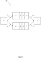
- FIG. 1 is a schematic of linked devices in a wireless network 10.
- a first access point 12 a second access point 14 and a client device 16, which are all configurable to communicate with one another.
- the first access point 12, the second access point 14 and the client device 16 are all wireless network devices.
- the first access point 12 is shown to have a processor 1 and a memory 2, as well as network interfaces 3, 4.
- the second access point 14 also has a processor 5, a memory 6 and network interfaces 7, 8.
- the client device 16 has a memory 22 and a processor 21 and network interfaces 23, 24.
- the first access point 12 is in active communication with the client device 16.
- the first access point 12 and the client device 16 exchange data via the network interfaces 4, 23.
- the link between the first access point 12 and the client device 16 is known as a floating link (FL) 26.
- the floating link 26 works based on mutual identification of the client device 16 to the access point 12 and of the access point 12 to the client device 16.
- the mutual identification is based on Media Access Control (MAC) addresses and each packet that is transmitted along the floating link 26 includes the source and destination MAC addresses in its header.
- MAC Media Access Control
- the first access point 12 has a virtual Media Access Control (vMAC) address instead of a conventional fixed MAC address.
- vMAC virtual Media Access Control
- the vMAC addresses are unique to the local area network (LAN) in which the client device 16 and the access point 12 are operating, but are not permanently linked to the access point 12 that has issued them.
- a vMAC address is assigned by the first access point 12 to identify itself to a client device 16 upon first interaction.
- the vMAC address is sourced either from the memory 2, or from a centralised database (described in relation to Figure 4 below).
- a vMAC address is generated based on a hash of a device's real MAC address.
- a vMAC address is based on any system that provides a usable address that is unique within the network.
- the first access point 12 monitors potentially superior pathways between other network devices and the client device 16 at its processor 1. In the event that a superior pathway is identified, the first access point 12 performs a handoff operation. In the handoff operation, the vMAC address that is used to identify the first access point 12 to the client device 16 is passed to the superior access point via network interfaces 3, 7. This is illustrated at Figure 1 , where the second access point 14 has a superior potential link with client device 16. The vMAC address of the first access point 12 is passed in a command 30 to the second access point 14. The command 30 instructs the second access point 14 to store the vMAC address in its memory 6 and to use it to identify itself to the client device 16. The determination of superior pathways is detailed below with reference to Figure 3 .
- the second access point 14 Once the second access point 14 has received a command 30 to instruct it to communicate with the client device 16, it forms a floating link 28 between a network interface 8 of the second access point 14 and a network interface 24 of the client device 16.
- Figure 1 depicts two network interfaces 3, 4 at the first access point 12, two network interfaces 7, 8 at the second access point 14 and two network interfaces 23, 24 at the client device 16, however, in other examples, the first access point 12, the second access point 14 and the client device 16 have one or more network interfaces.
- Different network interfaces allow the access points and client devices to operate using different communication methods, such as WiFi (RTM), Bluetooth (RTM), WiGig (RTM), ZigBee (RTM) and LiFi (RTM).
- the first access point 12 can communicate with the client device 16 using WiFi and a vMAC address, however the command 30 could be sent from the first access point 12 to the second access point 14 using a different communication method, such as a wired method, for example using an ethernet connection, or a different wireless method, for example, Bluetooth (RTM).
- a different communication method such as a wired method, for example using an ethernet connection, or a different wireless method, for example, Bluetooth (RTM).
- vMAC address that can be passed from the first access point 12 to the second access point 14 advantageously means that the access point with which the client device 16 is communicating changes in a favourable way so that the overall communication path is optimised, however, the client device 16 is unaware that the change has been made and therefore, beneficially, seamless use of the client device 16 over optimised channels is achieved without having to reboot the client device 16's wireless connection.
- a handoff operation is performed.
- the handoff operation is performed in a single step.
- the first access point 12 sends a command packet 30 to the second access point 14.
- the command packet 30 contains the vMAC address that the first access point 12 was using to identify itself to the client device 16 and instructions telling the second access point 14 to use the vMAC address to create a floating link 28 between the client device 16 and the second access point 14.
- the second access point 14 Upon receipt of the command packet 30 from the first access point 12, the second access point 14 transmits data throughout the network, informing other network devices that it has assumed the vMAC address and is using it to communicate with the client device 16.
- the data may be transmitted by being broadcast, or by unicasts directed to specific access points or network nodes.
- the second access point 14 uses the vMAC to communicate with the client device 16 whilst also monitoring for potentially superior routes of communication for the client device 16. In the event that a superior communication route is found with a different device, the vMAC is passed to that device, along with a command instructing the different device to use the vMAC to identify itself and communicate with the client device 16.
- a vMAC address is used for the wireless network devices 12, 14, 16 to identify one another in order to enable communication.
- different types of virtual address may be used for the devices to identify one another.
- virtual Bluetooth address vBD_ADDR
- similar mechanisms of virtual addresses are used in the context of IEEE 802.15 (ZigBee), IEEE 802.11ad (WiGig) and Visible Light Communication (LiFi).
- the command 30 from the first access point 12 to the second access point 14 contains the vMAC address so that the second access point 14 can seamlessly pick up communication with the client device 16.
- the command 30 also contains context information regarding the vMAC, such as the WPA2 encryption cypher and last known PHY link adaptation state.
- the client device For a client device to enter a mesh network using floating links and virtual address, the client device must initially associate with a node, such as an access point.
- the node with which it associates may be the first physical network node with which it attempts to associate. For example, for a WiFi device this would be the first access point to which an Associate Request is sent.
- This node generates the virtual address for the floating link and the node becomes the first Holder of the floating link.
- each access point in the floating link network has a list of virtual addresses (for every available physical layer such as WiFi or Bluetooth) that it can generate, while in another embodiment these addresses are drawn out of a central list.
- an Associate Request is sent to the first access point 12.
- the first access point 12 when the client device 16 enters the network 10, an Associate Request is sent to the first access point 12.
- the first access point 12 generates, either from memory 2, or from a centralised database (described below with reference to Figure 4 ), a virtual address.
- the virtual address is used to identify the first access point
- the current Holder for that floating link advertises this event throughout the network.
- a network node hears such a disconnect advertisement, it will check the floating link address against the list of virtual floating link addresses it has issued in the past, and, if the disconnected floating link is among them, free the entry for re-issuing.
- the client device 16 exits the network 10
- the first access point 12 advertises this event to other nodes in the network, for example the second access point 14.
- the virtual address that was used to connect the first access point 12 and the client device 16 is available for the second access point 14 to identify itself to the client device 16, if the re-entry dictates that forming that link 28 is preferable.
- the handoff operation is performed in a single step.
- the handoff operation is a phased procedure.
- the phased procedure advantageously deals with packets that are queued at an access point whilst the access point makes a decision to pass the virtual address to a different access point.
- Figure 2 is a schematic of an arrangement 40 showing the first access point 12, the second access point 14, the client device 16 and a third access point 18. There are shown data packets 42, 44 queued at the first access point 12 and data packets 46, 48 queued at the second access point 14.
- data is initially routed from the third access point 18 to the client device 16 via the first access point 12.
- data packets 42, 44 are sent from the third access point via link 29 to the first access point 12, where they are queued for further sending to the client device 16.
- the first access point 12 establishes a floating link 26 with the client device 16 and identifies itself using a vMAC address.
- the handoff from the first access point 12 to the second access point 14 is performed.
- the first access point 12 performs a first phase where the first access point 12 maintains the floating link 26 but sends a command 30 to the second access point 14 indicating that the handoff has been initiated.
- the first access point 12 continues to transmit queued data packets 42, 44, to the client device 16 using the floating link 26 based on the virtual address. Once the queue of data packets 42, 44 has been depleted and there are no more data packets to be sent from the first access point 12 to the client device 16, the second phase of the two phase handoff procedure commences and the second access point 14 starts to use the vMAC address to communicate with the client device over a floating link 28 using the vMAC address.
- the second access point 14 transmits data to other devices in the network, informing them that it is using the vMAC to communicate with the client device 16.
- the third access point 18 starts to send data packets 46, 48, to the client device 16 via the communication path 31 and the floating link 28.
- data packets directed to the first access point 12 are either dropped or routed to the client device 16 via a different route.
- the possibility of lost packets that are queued may not be significantly detrimental to the overall quality of the data consumed at a client device.
- the handoff operation is a three-phased operation.
- data is initially routed from the third access point 18 to the client device 16 via the first access point 12.
- data packets 42, 44 are sent from the third access point via link 29 to the first access point 12, where they are queued for further sending to the client device 16.
- the first access point 12 establishes a floating link 26 with the client device 16 and identifies itself using a vMAC address.
- the handoff from the first access point 12 to the second access point 14 is performed.
- the first access point 12 performs a first phase where the first access point 12 maintains the floating link 26 but sends a command 30 to the second access point 14 indicating that the handoff has been initiated.
- the first access point 12 continues to transmit queued data packets 42, 44, to the client device 16 using the floating link 26 based on the virtual address.
- the second access point 14 transmits data to other devices in the network, informing them that it is using the vMAC to communicate with the client device 16.
- the third access point 18 starts to send data packets 46, 48, to the client device 16 via the communication path 31 and the floating link 28.
- the second phase of the three-phase handoff commences and the second client device 14 sends a notification to the first access point 12, telling the first access point 12 that it has now notified the network of the change in present ownership of the vMAC address.
- the third phase of the three-phase handoff commences and the first access point 12 sends a notification to the second access point 14, telling it that the queue of data packets 42, 44 has been depleted.
- the second access point 14 then starts to transmit data packets 46, 48, which it has received and queued from the third access point 18, via floating link 28 to the client device 16.
- excess data packets are not lost by being sent to the first access point 12 once the second access point 14 has assumed the vMAC address and formed a floating link 28 with the client device 16.
- data packets directed to the first access point 12 are either dropped or routed to the client device 16 via a different route.
- a process S70 for determining the best communication pathway is initiated.
- the access point starts route discovery for the WiFi client destination, such as for the client device 16 of Figure 1 .
- the first access point 12 is initially in communication with the client device 16, identifying itself to the client device 16 using a virtual address.
- the first access point 12 uses a request/response mechanism to determine traffic through different pathways in a mesh network.
- a request such as a Beacon Request Frame, is sent by the first access point 12 to the client device 16 and to other nodes in the network, for example, the second access point 14 of Figure 1 .
- the second access point 14 also transmits requests to other nodes in the network.
- Each node in the network collects request frames and prepares and sends responses (such as Beacon Response Frames) to each of the request frames, containing information about the received request packets and corresponding data. This way, data, such as Received Signal Strength Indication (RSSI) values between different nodes are disseminated throughout the network, enabling determination of data throughputs in the network.
- RSSI Received Signal Strength Indication
- the process moves to step S74, whereby potential mesh routes in a mesh network are evaluated at the processor 1.
- the end-to-end throughput through alternative mesh routes in the network is evaluated. For example, with reference to Figure 1 , the first access point 12 determines traffic throughput to and from the client device 16 via each of the first access point 12 and the second access point 14.
- step S76 it is asked if the last hop formed by a floating link from the current access point is the best route that can be established. If it is (for example, if the connection between the first access point 12 and the client device 16 enables better data transfer than between the client device 16 and the second access point 14), then the process moves to step S78 and no action is taken. If it is not (for example, if the connection between the first access point 12 and the client device 16 enables less data transfer than between the client device 16 and the second access point 14), the process moves to step S80 and a handoff operation is performed to transfer information relating to the virtual address upon which the current floating link is based to the access point that does form the best last hop, i.e. the second access point 14 in this example.
- the process S70 is initiated periodically. However, in further examples, the process S70 is initiated by receipt at an access point of a packet with a MAC address that is not registered in a forwarding table of MAC addresses that is stored in the memory of the access point.
- the handoff operation at step S80 is performed in order to provide a station, such as a client device, with the strongest link to an access point in the network.
- a station such as a client device
- One way this can be done is by determining at step S76 that the best route on the last hop is determined by the Received Signal Strength Indication (RSSI) at the other access points in the network. This is done by having each access point periodically broadcast a control packet to other associated mesh access points with a list of client devices it can hear and their RSSIs.
- This RSSI estimation can be done by an AP to which the client is not currently associated by observing the RSSI of broadcast packets, such as Probe Requests or Clear-To-Send (CTS) messages.
- CTS Clear-To-Send
- the RSSI is used to estimate potential link capacity between the estimating AP and client. While raw RSSI can be used directly to estimate this capacity, other factors, such as channel width (20/40/80/160 MHz), noise level, number of available transmit and receive chains etc. can be used to form a more accurate estimate of potential link capacity.
- an access point When an access point learns from another access point that one of its current client devices can establish a better link with that access point, it will perform a floating link FL handoff to that access point.
- the access points attempt to maintain the best end-to-end link for the client device.
- the best end-to-end link is determined as the link which minimizes the airtime spent by the client for its uplink and downlink traffic, including airtime spent by the network, such as a Hybrid Mesh network, in getting the traffic to the access point which holds the floating link for the client device.
- the access points still broadcast client device RSSI information as described above, but instead of choosing the best link based on RSSI, the decision to move to step S80 is based on the access point holding the floating link chooses to handoff if the current traffic pattern of the client device (all uplink and downlink activity to all traffic sources and sinks) would be minimized by handing the floating link off to another access point.
- each access point is free to "commandeer" the floating link to the client device it wishes to transmit to directly.
- both the first access point 12 and second access point 14 in Figure 1 could, by turns, have traffic for the client device 16, as would be the case when the first access point 12 and the second access point 14 are connected to two different sources of traffic such as a Broadband Gateway and Satellite Set-Top Box.
- the primary distinction of this embodiment is the very small time scale for which the floating link is used by each access point, which may be as short as a single WiFi packet.
- One of the most useful scenarios incorporating this embodiment is when multiple access points joined to each other by strong backbone connections maintain concurrent sessions to a relatively lower capacity client, such as a mobile tablet receiving Satellite video and supplementary information (such as subtitles or application data) from the Internet at the same time.
- a relatively lower capacity client such as a mobile tablet receiving Satellite video and supplementary information (such as subtitles or application data) from the Internet at the same time.
- FIG 4 is an alternative embodiment of the invention described in respect to Figure 1 .
- a controller 13 having a processor 13a and a memory 13b.
- the controller 13 is connected to the first access point 12 via connection 13c.
- the connection 13c can be an ethernet connection, however, in further examples, the connection 13c is any type of connection that allows data to be passed between the controller 13 and the first access point 12.
- the controller 13 is connected to the first access point 12, however, in further examples, the controller 13 is connected to any number of access points or nodes in a network.
- the memory 13b contains a pool of virtual addresses.
- a virtual address to identify the first access point 12 to the client device 16 is assigned by the controller 13 from the pool of virtual addresses contained in the memory 13b.
- the controller 13 records the assignment of a virtual address from the pool of virtual addresses in the memory 13b and prevents the virtual address from being assigned for use by any other access point in the network.
- a different virtual address is assigned to the first access point 12, so that it can use the different virtual address to identify itself to the further client device.
- the different virtual address is assigned by the controller 13 to the first access point 12 from the remaining pool of virtual addresses in the memory 13b.
- the assignment of the different virtual address is recorded by the controller 13, which prevents the different virtual address from being assigned for use by any other access point in the network.
- the virtual address that was assigned to the first access point 12 to identify itself to the client device 16 is no longer required. Accordingly, the virtual address can be returned to the pool of available virtual addresses stored in the memory 13b. This is recorded and managed by the controller 13.
- Decoupling of a client device with an access point occurs when a message is received at the controller 13 that the access point no longer associates with the client device, when the client device has explicitly left.
- decoupling of a client device with an access point occurs when the connection between the client device and the access point times out. This occurs when communication between the client device and access point has not occurred for a predetermined amount of time.
- Figure 4 shows a centralised system for controlling the assignment and reuse of virtual addresses. This contrasts with the distributed architecture of Figure 1 , where the assignment and reuse of virtual addresses is controlled at the individual access points.
- the virtual address that was sourced from the controller 13 is passed between the first access point 12 and the second access point 14.
- the event is transmitted throughout the network 10, so that other nodes are aware that the virtual address is in use and are aware which node is using the virtual address.
- This information is transmitted in particular to the controller 13, so that an updated table of available virtual addresses is maintained in its memory 13b.
- the controller 13 is connected to the first access point 12.
- the controller 13 forms an integral part of the first access point 12, which is a master node.
- the controller 13 is a separate, stand-alone device.
- the controller 13 is responsible for determining route discovery for a client destination, as described with reference to Figure 3 .
- the controller 13 determines that the first access point 12 is initially in communication with the client device 16, identifying itself to the client device 16 using a virtual address.
- the controller 13 uses a request/response mechanism to determine traffic through different pathways in a mesh network.
- a request such as a Beacon Request Frame, is sent by the controller 13 to the client device 16 and to other nodes in the network, for example, the first and second access points 12, 14 of Figure 1 .
- the first and second access points 12, 14 also transmits requests to other nodes in the network.
- Each node in the network collects request frames and prepares and sends responses (such as Beacon Response Frames) to each of the request frames, containing information about the received request packets and corresponding data. This way, data, such as Received Signal Strength Indication (RSSI) values between different nodes are disseminated throughout the network, enabling determination of data throughputs in the network.
- RSSI Received Signal Strength Indication
- the controller 13 Once the controller 13 has received information from the route discovery process, the process moves to step S74, whereby potential mesh routes in a mesh network are evaluated at the processor 13a of the controller 13. The end-to-end throughput through alternative mesh routes in the network is evaluated. For example, with reference to Figure 1 , the controller 13 determines traffic throughput to and from the client device 16 via each of the first access point 12 and the second access point 14.
- step S76 it is asked if the last hop formed by a floating link from the current access point is the best route that can be established. If it is (for example, if the connection between the first access point 12 and the client device 16 enables better data transfer than between the client device 16 and the second access point 14), then the process moves to step S78 and no action is taken. If it is not (for example, if the connection between the first access point 12 and the client device 16 enables less data transfer than between the client device 16 and the second access point 14), the process moves to step S80 and a handoff operation is performed to transfer information relating to the virtual address upon which the current floating link is based to the access point that does form the best last hop, i.e.
- the process S70 is initiated periodically. However, in further examples, the process S70 is initiated by other means, such as receipt at an access point of a packet with a MAC address that is not registered in a forwarding table of MAC addresses that is stored in the memory of the access point.
- the handoff operation at step S80 is performed in order to provide a station, such as a client device, with the strongest link to an access point in the network.
- a station such as a client device
- One way this can be done is by determining at step S76 that the best route on the last hop is determined by the Received Signal Strength Indication (RSSI) at the other access points in the network. This is done by having each access point periodically broadcast a control packet to other associated mesh access points with a list of client devices it can hear and their RSSIs.
- This RSSI estimation can be done by an AP to which the client is not currently associated by observing the RSSI of broadcast packets, such as Probe Requests or Clear-To-Send (CTS) messages.
- CTS Clear-To-Send
- the RSSI is used to estimate potential link capacity between the estimating AP and client. While raw RSSI can be used directly to estimate this capacity, other factors, such as channel width (20/40/80/160 MHz), noise level, number of available transmit and receive chains etc. can be used to form a more accurate estimate of potential link capacity.
- a first and a second access point 12, 14 at Figure 1 there are shown a first and a second access point 12, 14 at Figure 1 , however, in further examples, there may be any number of access points.
- the decision to perform a handoff operation may be based on the end-to-end capacity of a connection including a wireless network device (such as an access point) and a client device versus the end-to-end capacity of a connection including a different wireless network device (such as a different access point) and the client device
- FIG 5 is an exemplary home network 100 comprising a residential gateway 101, satellite or DVB set-top box 102, access point 103 and a WiFi connected tablet 104.
- Each of the residential gateway 101, satellite or DVB set-top box 102 and access point 103 are also WiFi access points connected to each other via a mesh network.
- the WiFi connected tablet 104 can connect with any of the access points 101, 102, 103. Accordingly, as the WiFi tablet 104 is moved around the home network 100, the access point 101, 102, 103 with which it associates is chosen in accordance with the process described in relation to Figures 1 to 3 above. For example, the WiFi tablet 104 may initially communicate with the residential gateway 101 via the access point 103 and communication links 106, 108.
- the vMAC address used by the access point 103 may be handed off to the residential gateway 101 so that it communicate using the vMAC to identify itself to the tablet 104, without the tablet 104 becoming aware that the access point has changed.
- the WiFi tablet may be in communication with the satellite set top box 102, however, a superior pathway may exist between the access point 103 and the set top box 102, therefore the set top box 102 may pass its vMAC to the access point 103.
Landscapes
- Engineering & Computer Science (AREA)
- Computer Networks & Wireless Communication (AREA)
- Signal Processing (AREA)
- Databases & Information Systems (AREA)
- Mobile Radio Communication Systems (AREA)
Applications Claiming Priority (4)
| Application Number | Priority Date | Filing Date | Title |
|---|---|---|---|
| US201462052105P | 2014-09-18 | 2014-09-18 | |
| GB1501142.2A GB2530357B (en) | 2014-09-18 | 2015-01-23 | Floating links |
| PCT/EP2015/071515 WO2016042157A1 (fr) | 2014-09-18 | 2015-09-18 | Transfert de liaisons flottantes au moyen d'une identification de point d'accès virtuel |
| EP15785056.1A EP3195653B1 (fr) | 2014-09-18 | 2015-09-18 | Transfert de liaisons flottantes au moyen d'une identification de point d'accès virtuel |
Related Parent Applications (2)
| Application Number | Title | Priority Date | Filing Date |
|---|---|---|---|
| EP15785056.1A Division EP3195653B1 (fr) | 2014-09-18 | 2015-09-18 | Transfert de liaisons flottantes au moyen d'une identification de point d'accès virtuel |
| EP15785056.1A Division-Into EP3195653B1 (fr) | 2014-09-18 | 2015-09-18 | Transfert de liaisons flottantes au moyen d'une identification de point d'accès virtuel |
Publications (2)
| Publication Number | Publication Date |
|---|---|
| EP3917119A2 true EP3917119A2 (fr) | 2021-12-01 |
| EP3917119A3 EP3917119A3 (fr) | 2022-03-23 |
Family
ID=52673840
Family Applications (2)
| Application Number | Title | Priority Date | Filing Date |
|---|---|---|---|
| EP21178641.3A Pending EP3917119A3 (fr) | 2014-09-18 | 2015-09-18 | Transmission de liens flottants à l'aide du point d'accès virtuel identification |
| EP15785056.1A Active EP3195653B1 (fr) | 2014-09-18 | 2015-09-18 | Transfert de liaisons flottantes au moyen d'une identification de point d'accès virtuel |
Family Applications After (1)
| Application Number | Title | Priority Date | Filing Date |
|---|---|---|---|
| EP15785056.1A Active EP3195653B1 (fr) | 2014-09-18 | 2015-09-18 | Transfert de liaisons flottantes au moyen d'une identification de point d'accès virtuel |
Country Status (4)
| Country | Link |
|---|---|
| US (2) | US10278169B2 (fr) |
| EP (2) | EP3917119A3 (fr) |
| GB (1) | GB2530357B (fr) |
| WO (1) | WO2016042157A1 (fr) |
Families Citing this family (9)
| Publication number | Priority date | Publication date | Assignee | Title |
|---|---|---|---|---|
| KR102340917B1 (ko) * | 2015-06-12 | 2021-12-20 | 삼성전자주식회사 | 전자 장치 및 그 연결 방법 |
| US10230634B2 (en) * | 2015-09-25 | 2019-03-12 | Osram Sylvania Inc. | Route optimization using star-mesh hybrid topology in localized dense ad-hoc networks |
| CA2922449C (fr) | 2015-09-25 | 2024-04-30 | Osram Sylvania Inc. | Optimisation de route au moyen d'une topologie hybride etoile-maille dans les reseaux ad hoc denses localises |
| CN106792935B (zh) * | 2016-11-16 | 2020-07-17 | 广东新岸线科技有限公司 | 一种用户站点跨小区切换时实现用户数据接续传输的方法 |
| WO2018138577A1 (fr) * | 2017-01-25 | 2018-08-02 | Airties Kablosuz Iletisim Sanayi Ve Dis Ticaret A.S. | Topologies d'îlots et routage dans des réseaux maillés hybrides |
| US11197224B1 (en) * | 2018-02-19 | 2021-12-07 | Synapse Wireless, Inc. | Systems and methods for routing messages through wireless networks |
| US12348981B2 (en) * | 2022-03-09 | 2025-07-01 | Netgear, Inc. | Repurposing consumer electronic devices as nodes in wireless mesh networks |
| US12216604B2 (en) * | 2022-09-30 | 2025-02-04 | Mellanox Technologies, Ltd. | Virtual wire protocol for transmitting side band channels |
| WO2024099604A1 (fr) * | 2023-07-10 | 2024-05-16 | Lenovo (Singapore) Pte. Ltd. | Transfert de tâche de détection |
Citations (2)
| Publication number | Priority date | Publication date | Assignee | Title |
|---|---|---|---|---|
| GB1422183A (en) | 1972-05-30 | 1976-01-21 | Fujitsu Ltd | Control of road vehicle braking presentation cap and container fitted therewith |
| US20140362776A1 (en) * | 2013-06-07 | 2014-12-11 | Qualcomm Incorporated | Application aware association in wireless networks |
Family Cites Families (20)
| Publication number | Priority date | Publication date | Assignee | Title |
|---|---|---|---|---|
| US7016325B2 (en) * | 2001-01-18 | 2006-03-21 | Strix Systems, Inc. | Link context mobility method and system for providing such mobility, such as a system employing short range frequency hopping spread spectrum wireless protocols |
| US7590064B1 (en) * | 2004-07-20 | 2009-09-15 | Nortel Networks Limited | Method and system of flow control in multi-hop wireless access networks |
| JP4427415B2 (ja) * | 2004-08-05 | 2010-03-10 | 株式会社日立コミュニケーションテクノロジー | ハンドオフ制御方法、無線制御局及び無線基地局 |
| JP4558452B2 (ja) * | 2004-11-09 | 2010-10-06 | パナソニック株式会社 | マルチキャリア通信装置およびセル選択方法 |
| US7711361B2 (en) * | 2004-11-24 | 2010-05-04 | Azalea Networks | Method and system for distributed roaming services for mobile users on wireless mesh networks |
| US8068507B2 (en) * | 2005-06-14 | 2011-11-29 | Interdigital Technology Corporation | Method and system for conveying backhaul link information for intelligent selection of a mesh access point |
| WO2008031361A1 (fr) * | 2006-09-11 | 2008-03-20 | 3Dsp Corporation | Système multi-passerelle et procédés associés |
| JP4763560B2 (ja) * | 2006-09-14 | 2011-08-31 | 富士通株式会社 | 接続支援装置 |
| US8134995B2 (en) * | 2007-01-12 | 2012-03-13 | Samsung Electronics Co., Ltd. | Mobile ad-hoc network routing based upon hardware address |
| US20080320108A1 (en) * | 2007-06-20 | 2008-12-25 | Microsoft Corporation | Management Policies For Dense Wireless Access Point Infrastructures in Wireless Local Area Networks |
| US8442003B2 (en) * | 2007-09-06 | 2013-05-14 | Qualcomm Incorporated | Routing in a mesh network |
| US8571038B2 (en) * | 2007-10-24 | 2013-10-29 | Lantronix, Inc. | Method to tunnel UDP-based device discovery |
| US8223721B2 (en) * | 2007-11-29 | 2012-07-17 | Nokia Siemens Networks Oy | Mobile station handover using transferrable virtual access point address for wireless networks |
| JPWO2009119833A1 (ja) * | 2008-03-28 | 2011-07-28 | 日本電気株式会社 | 移動通信システム、異種アクセス網間ハンドオーバ方法及び移動端末、サーバ |
| JP4679616B2 (ja) * | 2008-08-19 | 2011-04-27 | 株式会社バッファロー | 無線lan中継装置、無線lan中継方法およびコンピュータプログラム |
| US8542836B2 (en) * | 2010-12-01 | 2013-09-24 | Juniper Networks, Inc. | System, apparatus and methods for highly scalable continuous roaming within a wireless network |
| CN102246495A (zh) * | 2011-04-20 | 2011-11-16 | 华为技术有限公司 | 一种防止地址冲突的方法及接入节点 |
| US9055519B2 (en) * | 2011-09-09 | 2015-06-09 | Qualcomm Incorporated | Access Points selection apparatus and methods |
| US9699701B2 (en) * | 2012-08-10 | 2017-07-04 | Qualcomm Incorporated | Mobility operation in LTE |
| WO2014126445A1 (fr) * | 2013-02-18 | 2014-08-21 | Lg Electronics Inc. | Procédé et appareil de mise en oeuvre d'une transmission de données dans un système de communication sans fil |
-
2015
- 2015-01-23 GB GB1501142.2A patent/GB2530357B/en active Active
- 2015-09-18 WO PCT/EP2015/071515 patent/WO2016042157A1/fr not_active Ceased
- 2015-09-18 EP EP21178641.3A patent/EP3917119A3/fr active Pending
- 2015-09-18 EP EP15785056.1A patent/EP3195653B1/fr active Active
- 2015-09-18 US US14/858,274 patent/US10278169B2/en active Active
-
2019
- 2019-01-04 US US16/240,103 patent/US10993222B2/en active Active
Patent Citations (2)
| Publication number | Priority date | Publication date | Assignee | Title |
|---|---|---|---|---|
| GB1422183A (en) | 1972-05-30 | 1976-01-21 | Fujitsu Ltd | Control of road vehicle braking presentation cap and container fitted therewith |
| US20140362776A1 (en) * | 2013-06-07 | 2014-12-11 | Qualcomm Incorporated | Application aware association in wireless networks |
Also Published As
| Publication number | Publication date |
|---|---|
| WO2016042157A1 (fr) | 2016-03-24 |
| GB2530357B (en) | 2019-02-06 |
| US10278169B2 (en) | 2019-04-30 |
| GB201501142D0 (en) | 2015-03-11 |
| EP3917119A3 (fr) | 2022-03-23 |
| GB2530357A (en) | 2016-03-23 |
| WO2016042157A4 (fr) | 2016-08-25 |
| US20190141701A1 (en) | 2019-05-09 |
| US20160088615A1 (en) | 2016-03-24 |
| US10993222B2 (en) | 2021-04-27 |
| EP3195653A1 (fr) | 2017-07-26 |
| EP3195653B1 (fr) | 2021-07-21 |
Similar Documents
| Publication | Publication Date | Title |
|---|---|---|
| EP3195653B1 (fr) | Transfert de liaisons flottantes au moyen d'une identification de point d'accès virtuel | |
| AU2019271960B2 (en) | Method of controlling handover in mobile communication networks and apparatus and system implementing the method | |
| US10602379B2 (en) | Wireless communication method, wireless communication device and non-transitory computer readable recording medium thereof | |
| JP4265620B2 (ja) | アクセス制御装置、無線装置、ネットワーク、アクセス制御方法及びアクセス制御プログラム | |
| CN105580428A (zh) | 接入点协调的无线设备重新关联 | |
| TWI602451B (zh) | 用戶端裝置在無線區域網路接取點間導引連線方法和系統 | |
| EP3386240B1 (fr) | Procédé de basculement dans un réseau maître-esclave, dispositif maître, dispositif esclave, et système | |
| WO2024052050A1 (fr) | Communication de relais u2u | |
| JP5274422B2 (ja) | 無線通信システムおよびハンドオーバ制御方法 | |
| JP5116549B2 (ja) | 無線中継局、マルチホップセルラーゲートウェイおよび通信システム | |
| EP3133773B1 (fr) | Procédé, appareil et système pour une interaction de données entre des points d'accès (ap) dans un système wifi | |
| KR20120072060A (ko) | 연속된 연결성이 결여된 네트워크 환경 기반 노드 장치, 노드 관리 장치, 통신 시스템 및 노드 관리 방법 | |
| JP6112837B2 (ja) | 移動通信システム、移動通信装置、固定中継装置及び集線装置 | |
| JP6112838B2 (ja) | 移動通信システム、移動通信装置、固定中継装置及び集線装置 | |
| WO2021028966A1 (fr) | Dispositif de station de terminal radio, dispositif de station de gestion, système de radiocommunication et procédé de radiocommunication | |
| HK40031979A (en) | Method of controlling handover in mobile communication networks and apparatus implementing the method | |
| JP2018042138A (ja) | 通信切替装置、アクセスポイント、端末、通信切替方法 |
Legal Events
| Date | Code | Title | Description |
|---|---|---|---|
| PUAI | Public reference made under article 153(3) epc to a published international application that has entered the european phase |
Free format text: ORIGINAL CODE: 0009012 |
|
| STAA | Information on the status of an ep patent application or granted ep patent |
Free format text: STATUS: REQUEST FOR EXAMINATION WAS MADE |
|
| 17P | Request for examination filed |
Effective date: 20210609 |
|
| AC | Divisional application: reference to earlier application |
Ref document number: 3195653 Country of ref document: EP Kind code of ref document: P |
|
| AK | Designated contracting states |
Kind code of ref document: A2 Designated state(s): AL AT BE BG CH CY CZ DE DK EE ES FI FR GB GR HR HU IE IS IT LI LT LU LV MC MK MT NL NO PL PT RO RS SE SI SK SM TR |
|
| REG | Reference to a national code |
Ref country code: DE Ref legal event code: R079 Free format text: PREVIOUS MAIN CLASS: H04L0029120000 Ipc: H04W0040020000 |
|
| PUAL | Search report despatched |
Free format text: ORIGINAL CODE: 0009013 |
|
| AK | Designated contracting states |
Kind code of ref document: A3 Designated state(s): AL AT BE BG CH CY CZ DE DK EE ES FI FR GB GR HR HU IE IS IT LI LT LU LV MC MK MT NL NO PL PT RO RS SE SI SK SM TR |
|
| RIC1 | Information provided on ipc code assigned before grant |
Ipc: H04L 61/5046 20220101ALI20220216BHEP Ipc: H04L 101/622 20220101ALI20220216BHEP Ipc: H04L 61/5038 20220101ALI20220216BHEP Ipc: H04W 8/26 20090101ALI20220216BHEP Ipc: H04L 101/681 20220101ALI20220216BHEP Ipc: H04W 36/00 20090101ALI20220216BHEP Ipc: H04W 40/36 20090101ALI20220216BHEP Ipc: H04W 40/02 20090101AFI20220216BHEP |
|
| RAP1 | Party data changed (applicant data changed or rights of an application transferred) |
Owner name: AIRTIES SAS |
|
| STAA | Information on the status of an ep patent application or granted ep patent |
Free format text: STATUS: EXAMINATION IS IN PROGRESS |
|
| 17Q | First examination report despatched |
Effective date: 20240529 |