EP3917251B1 - Datenübertragungsverfahren und -vorrichtung - Google Patents
Datenübertragungsverfahren und -vorrichtung Download PDFInfo
- Publication number
- EP3917251B1 EP3917251B1 EP21187353.4A EP21187353A EP3917251B1 EP 3917251 B1 EP3917251 B1 EP 3917251B1 EP 21187353 A EP21187353 A EP 21187353A EP 3917251 B1 EP3917251 B1 EP 3917251B1
- Authority
- EP
- European Patent Office
- Prior art keywords
- time
- domain resource
- domain
- resource
- indication information
- Prior art date
- Legal status (The legal status is an assumption and is not a legal conclusion. Google has not performed a legal analysis and makes no representation as to the accuracy of the status listed.)
- Active
Links
Images




Classifications
-
- H—ELECTRICITY
- H04—ELECTRIC COMMUNICATION TECHNIQUE
- H04L—TRANSMISSION OF DIGITAL INFORMATION, e.g. TELEGRAPHIC COMMUNICATION
- H04L5/00—Arrangements affording multiple use of the transmission path
- H04L5/0001—Arrangements for dividing the transmission path
- H04L5/0003—Two-dimensional division
- H04L5/0005—Time-frequency
-
- H—ELECTRICITY
- H04—ELECTRIC COMMUNICATION TECHNIQUE
- H04L—TRANSMISSION OF DIGITAL INFORMATION, e.g. TELEGRAPHIC COMMUNICATION
- H04L5/00—Arrangements affording multiple use of the transmission path
- H04L5/0001—Arrangements for dividing the transmission path
- H04L5/0003—Two-dimensional division
- H04L5/0005—Time-frequency
- H04L5/0007—Time-frequency the frequencies being orthogonal, e.g. OFDM(A) or DMT
- H04L5/001—Time-frequency the frequencies being orthogonal, e.g. OFDM(A) or DMT the frequencies being arranged in component carriers
-
- H—ELECTRICITY
- H04—ELECTRIC COMMUNICATION TECHNIQUE
- H04L—TRANSMISSION OF DIGITAL INFORMATION, e.g. TELEGRAPHIC COMMUNICATION
- H04L5/00—Arrangements affording multiple use of the transmission path
- H04L5/003—Arrangements for allocating sub-channels of the transmission path
-
- H—ELECTRICITY
- H04—ELECTRIC COMMUNICATION TECHNIQUE
- H04L—TRANSMISSION OF DIGITAL INFORMATION, e.g. TELEGRAPHIC COMMUNICATION
- H04L5/00—Arrangements affording multiple use of the transmission path
- H04L5/003—Arrangements for allocating sub-channels of the transmission path
- H04L5/0032—Distributed allocation, i.e. involving a plurality of allocating devices, each making partial allocation
- H04L5/0035—Resource allocation in a cooperative multipoint environment
-
- H—ELECTRICITY
- H04—ELECTRIC COMMUNICATION TECHNIQUE
- H04L—TRANSMISSION OF DIGITAL INFORMATION, e.g. TELEGRAPHIC COMMUNICATION
- H04L5/00—Arrangements affording multiple use of the transmission path
- H04L5/003—Arrangements for allocating sub-channels of the transmission path
- H04L5/0042—Intra-user or intra-terminal allocation
-
- H—ELECTRICITY
- H04—ELECTRIC COMMUNICATION TECHNIQUE
- H04L—TRANSMISSION OF DIGITAL INFORMATION, e.g. TELEGRAPHIC COMMUNICATION
- H04L5/00—Arrangements affording multiple use of the transmission path
- H04L5/003—Arrangements for allocating sub-channels of the transmission path
- H04L5/0044—Allocation of payload; Allocation of data channels, e.g. PDSCH or PUSCH
-
- H—ELECTRICITY
- H04—ELECTRIC COMMUNICATION TECHNIQUE
- H04L—TRANSMISSION OF DIGITAL INFORMATION, e.g. TELEGRAPHIC COMMUNICATION
- H04L5/00—Arrangements affording multiple use of the transmission path
- H04L5/003—Arrangements for allocating sub-channels of the transmission path
- H04L5/0048—Allocation of pilot signals, i.e. of signals known to the receiver
-
- H—ELECTRICITY
- H04—ELECTRIC COMMUNICATION TECHNIQUE
- H04L—TRANSMISSION OF DIGITAL INFORMATION, e.g. TELEGRAPHIC COMMUNICATION
- H04L5/00—Arrangements affording multiple use of the transmission path
- H04L5/003—Arrangements for allocating sub-channels of the transmission path
- H04L5/0053—Allocation of signalling, i.e. of overhead other than pilot signals
-
- H—ELECTRICITY
- H04—ELECTRIC COMMUNICATION TECHNIQUE
- H04L—TRANSMISSION OF DIGITAL INFORMATION, e.g. TELEGRAPHIC COMMUNICATION
- H04L5/00—Arrangements affording multiple use of the transmission path
- H04L5/003—Arrangements for allocating sub-channels of the transmission path
- H04L5/0058—Allocation criteria
- H04L5/0073—Allocation arrangements that take into account other cell interferences
-
- H—ELECTRICITY
- H04—ELECTRIC COMMUNICATION TECHNIQUE
- H04L—TRANSMISSION OF DIGITAL INFORMATION, e.g. TELEGRAPHIC COMMUNICATION
- H04L5/00—Arrangements affording multiple use of the transmission path
- H04L5/0091—Signalling for the administration of the divided path, e.g. signalling of configuration information
- H04L5/0094—Indication of how sub-channels of the path are allocated
-
- H—ELECTRICITY
- H04—ELECTRIC COMMUNICATION TECHNIQUE
- H04W—WIRELESS COMMUNICATION NETWORKS
- H04W72/00—Local resource management
- H04W72/04—Wireless resource allocation
-
- H—ELECTRICITY
- H04—ELECTRIC COMMUNICATION TECHNIQUE
- H04W—WIRELESS COMMUNICATION NETWORKS
- H04W72/00—Local resource management
- H04W72/04—Wireless resource allocation
- H04W72/044—Wireless resource allocation based on the type of the allocated resource
- H04W72/0446—Resources in time domain, e.g. slots or frames
-
- H—ELECTRICITY
- H04—ELECTRIC COMMUNICATION TECHNIQUE
- H04W—WIRELESS COMMUNICATION NETWORKS
- H04W72/00—Local resource management
- H04W72/04—Wireless resource allocation
- H04W72/044—Wireless resource allocation based on the type of the allocated resource
- H04W72/0453—Resources in frequency domain, e.g. a carrier in FDMA
-
- H—ELECTRICITY
- H04—ELECTRIC COMMUNICATION TECHNIQUE
- H04W—WIRELESS COMMUNICATION NETWORKS
- H04W72/00—Local resource management
- H04W72/12—Wireless traffic scheduling
- H04W72/1263—Mapping of traffic onto schedule, e.g. scheduled allocation or multiplexing of flows
- H04W72/1268—Mapping of traffic onto schedule, e.g. scheduled allocation or multiplexing of flows of uplink data flows
-
- H—ELECTRICITY
- H04—ELECTRIC COMMUNICATION TECHNIQUE
- H04W—WIRELESS COMMUNICATION NETWORKS
- H04W72/00—Local resource management
- H04W72/12—Wireless traffic scheduling
- H04W72/1263—Mapping of traffic onto schedule, e.g. scheduled allocation or multiplexing of flows
- H04W72/1273—Mapping of traffic onto schedule, e.g. scheduled allocation or multiplexing of flows of downlink data flows
-
- H—ELECTRICITY
- H04—ELECTRIC COMMUNICATION TECHNIQUE
- H04W—WIRELESS COMMUNICATION NETWORKS
- H04W72/00—Local resource management
- H04W72/20—Control channels or signalling for resource management
- H04W72/23—Control channels or signalling for resource management in the downlink direction of a wireless link, i.e. towards a terminal
Definitions
- Embodiments of the disclosure relate to the field of communication, and more particularly to a data transmission method.
- a sub-frame is taken as a scheduling unit.
- first few symbols in each sub-frame may be configured as control channel resources, and the control channel resources span the whole system bandwidth on a frequency domain.
- a starting symbol of a data transmission resource is usually a first symbol immediately next to a control channel resource, and an ending symbol of the data transmission channel is usually an ending symbol of a sub-frame. Therefore, a length of a data transmission resource on a time domain is kept unchanged in a sub-frame and on the whole system bandwidth.
- a future wireless communication system (for example, 5th-Generation (5G)) focuses on supporting higher system performance, and is required to support various service types, different deployment scenarios and a wider spectral range. How to improve system performance is a research hot spot in this field.
- 5G 5th-Generation
- WO 2012/109542 A1 discloses a method for receiving an enhanced control channel E-PDCCH.
- MEDIATEK INC Multiplexing of PUCCH and other channels
- 3GPP DRAFT R1-1612140 discloses that indication the index of starting OFDM symbol of PUSCH shall be introduced into DCI.
- LG ELECTRONICS “Remaining details on Frame Structure”, 3GPP DRAFT R1-1611780 FS , discloses that dynamic indication of reserved resources should be supported in NR.
- INTEL CORPORATION “NR frame structure for forward compatibility", 3GPP R1-1609509 , discloses that NR supports dynamic signaling of reservation resources within a slot.
- the embodiments of the disclosure provide a data transmission method, which may improve system performance.
- a network device and two terminal devices are exemplarily illustrated in FIG. 2 .
- the wireless communication system 100 may include multiple network devices and another number of terminal devices may be included in coverage of each network device. There are no limits made thereto in the embodiments of the disclosure.
- a time-frequency resource region may include a control channel resource and a data transmission channel.
- the control channel resource may include at least one physical resource block configured to transmit a control channel
- the data transmission resource may include at least one physical resource block for data transmission.
- the control channel resource may not span the whole system bandwidth but only appears in some physical resource blocks, and then the terminal device is not required to detect the control channel on the whole system bandwidth, so that power consumption of the terminal device is reduced.
- a scheduling unit may refer to a time-domain resource element implementing a data transmission of the terminal device scheduled by the network device.
- a scheduling unit may correspond to one or more sub-frames, slots or mini-slots on a time domain.
- an uplink/downlink scheduling time-domain resource may refer to a time-domain resource occupied by scheduled data transmission, and may specifically be a time-domain resource configured to transmit uplink/downlink data in the scheduling unit, or may be part of the time-domain resource configured to transmit the uplink/downlink data in the scheduling unit.
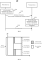
- FIG. 3 illustrates a transmission method 200 according to an embodiment of the disclosure.
- the transmission method 200 may be applied to the wireless communication system 100 illustrated in FIG. 2 .
- the embodiment of the disclosure is not limited thereto.
- the first time-frequency resource region may include multiple physical resource blocks.
- the time-frequency resource region corresponds to a scheduling unit on a time domain, and corresponds to part of the system bandwidth on a frequency domain.
- the downlink scheduling time-domain resource may correspond to a data transmission resource configured to transmit downlink data in the time-frequency resource region.
- the embodiment of the disclosure is not limited thereto.
- downlink data time-domain resources in different time-frequency resource regions may be at different positions in the time-frequency resource regions.
- Different time-frequency resource regions corresponding to a same time-domain resource and corresponding to different frequency bands include different downlink data time-domain resources.
- the first time-frequency resource region and a second time-frequency resource region correspond to a same time-domain resource and correspond to different frequency-domain resources respectively
- a starting symbol of the first downlink data time-domain resource in the first time-frequency resource region may be different from a starting symbol of a second downlink data time-domain resource in the second time-frequency resource region
- an ending symbol of the first downlink data time-domain resource is the same as an ending symbol of the second downlink data time-domain resource, for example, both of them are ending symbols of the first time-frequency resource region and the second time-frequency resource region
- the starting symbol of the first downlink data time-domain resource is the same as the starting symbol of the second downlink data time-domain resource, but a time-domain length of the first downlink data time-domain resource is different from a time-domain length of the second downlink data time-domain resource.
- the embodiment of the disclosure is not limited thereto.
- the indication information is specifically configured to indicate the starting symbol, time-domain length and ending symbol of the first downlink data time-domain resource.
- the terminal device may determine the downlink scheduling time-domain resource allocated by the network device in combination with the primary DCI and the secondary DCI.
- the primary DCI may be a common control channel, and all terminal devices may acquire information from the channel.
- the secondary DCI may be a UE-specific control channel. The embodiment of the disclosure is not limited thereto.
- the terminal device may determine the first downlink scheduling time-domain resource according to the information, in the indication information, about the control channel resource. For example, the terminal device may determine the starting symbol of the first downlink data time-domain resource according to the time-domain length, in the indication information, of the control channel resource and determine the first downlink scheduling time-domain resource according to the starting symbol of the first downlink data time-domain resource. Specifically, the terminal device may determine an ending symbol of the control channel resource according to the time-domain length of the control channel resource and determine the starting symbol of the first downlink data time-domain resource to be an Nth symbol after the ending symbol of the control channel resource. N may be an integer more than or equal to 1, and a specific numerical value of N may be defined or preconfigured in a protocol. The embodiment of the disclosure is not limited thereto.
- the indication information is specifically configured to indicate the starting symbol of the first downlink data time-domain resource.
- the ending symbol or time-domain length of the first downlink data time-domain resource may be defined or preconfigured in the protocol.
- the ending symbol of the first downlink data time-domain resource may be an ending symbol of the first time-frequency resource region, and in such case, the terminal device may determine the first downlink scheduling time-domain resource according to the starting symbol and ending symbol of the first downlink data time-domain resource.
- the embodiment of the disclosure is not limited thereto.
- FIG. 8 illustrates a transmission method 300 according to an embodiment of the disclosure not being part of the invention.
- the transmission method 300 may be applied to the wireless communication system 100 illustrated in FIG. 2 .
- the embodiment of the disclosure is not limited thereto.
- a network device determines an uplink scheduling time-domain resource, called a first uplink scheduling time-domain resource hereinafter, configured to transmit uplink data in a first scheduling unit.
- the network device sends indication information to a terminal device.
- the indication information indicates the first uplink scheduling time-domain resource in the first scheduling unit.
- the network device may transmit high-layer signaling to the terminal device, the high-layer signaling carrying the indication information.
- the network device may transmit physical-layer signaling to the terminal device, the physical-layer signaling carrying the indication information.
- the physical-layer signaling may specifically be a physical-layer common signal or a UE-specific control signal. There are no limits made thereto in the embodiment of the disclosure.
- the network device may indicate the uplink scheduling time-domain resource allocated for the terminal device through both of the high-layer signaling or the physical-layer signaling.
- the indication information may explicitly or implicitly indicate the first uplink scheduling time-domain resource.
- the indication information may include at least one of information about the starting symbol of the first uplink scheduling time-domain resource, information about the time-domain length and information about the ending symbol.
- the network device may indicate at least one of the starting symbol, time-domain length and ending symbol of the uplink scheduling time-domain resource in each scheduling unit through the high-layer signaling.
- the network device may also dynamically indicate at least one of a starting symbol, time-domain length or ending symbol of at least one physical resource block allocated for the terminal device through the physical-layer signaling.
- the embodiment of the disclosure is not limited thereto.
- the indication information may specifically be configured to indicate the starting symbol of the first uplink scheduling time-domain resource.
- the ending symbol or time-domain length of the first uplink scheduling time-domain resource may be defined or preconfigured in the protocol.
- the ending symbol of the first uplink scheduling time-domain resource may be an ending symbol of the first scheduling unit, and in such case, the terminal device may determine the first uplink scheduling time-domain resource according to the starting symbol and ending symbol of the first uplink scheduling time-domain resource.
- the embodiment of the disclosure is not limited thereto.
- the first scheduling unit may specifically a self-contained scheduling unit.
- the network device may transmit a common control signal, and the common control signal may contain information about the first uplink scheduling time-domain resource.
- the common control signal may contain information about an uplink and downlink switching time period in the first scheduling unit.
- the terminal device may determine the first uplink scheduling time-domain resource according to the information about the uplink and downlink switching time period.
- the terminal device may determine an ending symbol of the uplink and downlink switching time period according to the information about the uplink and downlink switching time period, determine the starting symbol of the first uplink scheduling time-domain resource to be a first symbol immediately next to the ending symbol of the uplink and downlink switching time period and determine the first uplink scheduling time-domain resource according to the determined starting symbol.
- the embodiment of the disclosure is not limited thereto.
- the indication information may also be specifically configured to indicate the time-domain length of the first uplink scheduling time-domain resource.
- the first scheduling unit may include multiple mini-slots.
- the first uplink scheduling time-domain resource may include at least two mini-slots in the multiple mini-slots.
- the network device may perform cross-mini-slot scheduling.
- the network device may transmit the UE-specific control signal to the terminal device on a first mini-slot in the first scheduling unit.
- the UE-specific control signal indicates the time-domain length of the first uplink scheduling time-domain resource.
- the first uplink scheduling time-domain resource includes at least two mini-slots after the first mini-slot.
- the UE-specific control signal may indicate the number of symbols in the first uplink scheduling time-domain resource.
- the terminal device may determine the time-domain length of the first uplink scheduling time-domain resource according to the indication information and determine the first uplink scheduling time-domain resource according to the determined time-domain length.
- the embodiment of the disclosure is not limited thereto.
- the indication information may also be specifically configured to indicate the ending symbol of the first uplink scheduling time-domain resource.
- the embodiment of the disclosure is not limited thereto.
- the starting symbol of the uplink scheduling time-domain resource may be a first symbol immediately next to the uplink and downlink switching time period
- the ending symbol of the uplink scheduling time-domain resource may be the ending symbol of the control channel of the short format.
- the embodiment of the disclosure is not limited thereto.
- uplink data transmission resources allocated by the network device for the terminal device include different subcarrier spacings
- the multiple uplink scheduling time-domain resources with different subcarrier spacings may be based on the uplink scheduling time-domain resource with a largest time-domain granularity.
- the embodiment of the disclosure is not limited thereto.
- the indication information may contain information about a third uplink scheduling time-domain resource in a third time-frequency resource region, the third time-frequency resource region is a scheduling unit with a minimum subcarrier spacing in the multiple time-frequency resource regions.
- the terminal device may determine an ending moment of the third uplink scheduling time-domain resource according to the indication information and determine a moment corresponding to the ending symbol of the first uplink scheduling time-domain resource to be the ending moment of the third uplink scheduling time-domain resource.
- the terminal device may determine the ending symbol of the first downlink data time-domain resource according to the ending moment of the third downlink data time-domain resource.
- the network device may configure the multiple time-frequency resource regions for uplink data transmission of the terminal device in the first scheduling unit.
- a starting moment of the first uplink scheduling time-domain resource may be the same as or different from a starting moment of the third uplink scheduling time-domain resource.
- the terminal device performs data transmission with the network device on the first uplink scheduling time-domain resource.
- the network device determines the first uplink scheduling time-domain resource in the first scheduling unit and sends the indication information configured to indicate the first uplink scheduling time-domain resource to the terminal device, and the terminal device determines the first uplink scheduling time-domain resource according to the indication information and sends the uplink data to the network device on the first uplink scheduling time-domain resource, so that system performance may be improved, and different service requirements are favorably supported.
- FIG. 4 to FIG. 7 and FIG. 9 are adopted not to limit the scope of the embodiments of the disclosure but only to help those skilled in the art to better understand the embodiments of the disclosure. It is apparent that those skilled in the art may make various equivalent modifications or variations according to the illustrated examples, and such modifications or variations shall also fall within the scope of the embodiments of the disclosure.
- FIG. 10 illustrates a data transmission device 400 according to an embodiment of the disclosure, which includes a receiving unit 410 and a determination unit 420.
- the receiving unit 410 is configured to receive indication information from a network device.
- the indication information indicates a first downlink scheduling time-domain resource in a first time-frequency resource region and a frequency-domain resource in the first time-frequency resource region is a part of a system bandwidth.
- the determination unit 420 is configured to determine the first downlink scheduling time-domain resource according to the indication information received by the receiving unit 410.
- the receiving unit 410 is further configured to receive data from the network device on the first downlink data time-domain resource determined by the determination unit 420.
- the indication information is configured to indicate at least one of a starting symbol, time-domain length or ending symbol of the first downlink data time-domain resource.
- the first downlink scheduling time-domain resource is different from a second downlink scheduling time-domain resource in a second time-frequency resource region, and the first time-frequency resource region and the second time-frequency resource region correspond to a same time-domain resource and correspond to different frequency-domain resources respectively.
- the first downlink scheduling time-domain resource is different from the second downlink scheduling time-domain resource in the second time-frequency resource region includes that:
- a starting symbol of the first downlink data time-domain resource is immediately next to an ending symbol of a control channel resource in the first time-frequency resource region; or the starting symbol of the first downlink data time-domain resource is a spaced from the ending symbol of the control channel resource in the first time-frequency resource region by at least one symbol.
- the indication information includes information about the control channel resource in the first time-frequency resource region.
- the determination unit 420 is specifically configured to determine the starting symbol of the first downlink data time-domain resource according to the information about the control channel resource.
- the first time-frequency resource region includes a self-contained scheduling unit, and the self-contained scheduling unit includes a downlink transmission time period, an uplink and downlink switching time period and an uplink transmission time period.
- the indication information includes information about the uplink and downlink switching time period in the self-contained scheduling unit.
- the determination unit 420 is specifically configured to determine the ending symbol of the first downlink data time-domain resource according to the information about the uplink and downlink switching time period.
- the receiving unit 410 is specifically configured to receive high-layer signaling from the network device, the high-layer signaling or a physical-layer common signal carrying the indication information; or
- the first downlink data time-domain resource includes multiple mini-slots, and the indication information is configured to indicate a total length of the multiple mini-slots.
- the indication information includes information about a third downlink scheduling time-domain resource in a third time-frequency resource region.
- the third time-frequency resource region is the time-frequency resource region with a minimum subcarrier spacing in the multiple time-frequency resource regions.
- the determination unit 420 is specifically configured to determine an ending moment of the third downlink data time-domain resource according to the indication information and determine a moment corresponding to the ending symbol of the first downlink data time-domain resource as the ending moment of the third downlink data time-domain resource.
- the device 400 described herein is embodied in form of functional unit.
- the device 400 may specifically be the terminal device in the abovementioned embodiments and the device 400 may be configured to execute each flow and/or step corresponding to the terminal device in the abovementioned method embodiments, which will not be elaborated herein for avoiding repetitions.
- FIG. 11 illustrates a data transmission device 500 according to another embodiment of the disclosure, which includes a receiving unit 510, a determination unit 520 and a transmitting unit 530.
- the receiving unit 510 is configured to receive indication information from a network device.
- the indication information indicates a first uplink scheduling time-domain resource which is configured to transmit uplink data and in a first scheduling unit.
- a time-domain position of the first uplink scheduling time-domain resource in the first scheduling unit is different from a time-domain position of a second uplink scheduling time-domain resource in a second scheduling unit and the second uplink scheduling time-domain resource is a time-domain resource which is configured to transmit the uplink data and in the second scheduling unit.
- the determination unit 520 is configured to determine the first uplink scheduling time-domain resource according to the indication information received by the receiving unit 510.
- the transmitting unit 530 is configured to transmit data to the network device on the first uplink scheduling time-domain resource determined by the determination unit 520.
- the indication information is configured to indicate at least one of a starting symbol, time-domain length or ending symbol of the first uplink scheduling time-domain resource.
- the first uplink scheduling time-domain resource is different from a second uplink scheduling time-domain resource includes that:
- the first scheduling unit is specifically a self-contained scheduling unit, and the self-contained scheduling unit includes a downlink transmission time period, an uplink and downlink switching time period and an uplink transmission time period.
- the starting symbol of the first uplink scheduling time-domain resource is a starting symbol of a control channel of a short format
- the ending symbol of the first uplink scheduling time-domain resource is an ending symbol of the control channel of the short format
- the starting symbol of the first uplink scheduling time-domain resource is a first symbol immediately next to the uplink and downlink switching time period
- the ending symbol of the first uplink scheduling time-domain resource is a symbol immediately previous to the control channel of the short format.
- the starting symbol of the first uplink scheduling time-domain resource is a first symbol immediately next to the uplink and downlink switching time period
- the ending symbol of the first uplink scheduling time-domain resource is the ending symbol of the control channel of the short format
- the receiving unit 510 is specifically configured to receive high-layer signaling from the network device, the high-layer signaling or a physical-layer common signal carrying the indication information; or
- the first uplink scheduling time-domain resource includes multiple mini-slots, and the indication information is configured to indicate a total length of the multiple mini-slots.
- the indication information includes information about a third uplink scheduling time-domain resource in a third time-frequency resource region.
- the third time-frequency resource region is the time-domain resource region with a minimum subcarrier spacing in the multiple time-frequency resource regions.
- the determination unit 520 is specifically configured to determine an ending moment of the third uplink data time-domain resource according to the indication information and determine a moment corresponding to the ending symbol of the first uplink data time-domain resource to be the ending moment of the third uplink data time-domain resource.
- the device 500 described herein is embodied in form of functional unit.
- the device 500 may specifically be the terminal device in the abovementioned embodiments and the device 500 may be configured to execute each flow and/or step corresponding to the terminal device in the abovementioned method embodiments, which will not be elaborated herein for avoiding repetitions.
- FIG. 12 illustrates a data transmission device 600 according to another embodiment of the disclosure, which includes a determination unit 610 and a transmitting unit 620.
- the determination unit 610 is configured to determine a first downlink scheduling time-domain resource in a first time-frequency resource region.
- the frequency-domain resource in the first time-frequency resource region is a part of a system bandwidth.
- the transmitting unit 620 is configured to transmit indication information to a terminal device.
- the indication information indicates the first uplink scheduling time-domain resource determined by the determination unit 610.
- the indication information is configured to indicate at least one of a starting symbol, time-domain length or ending symbol of the first downlink data time-domain resource.
- the first downlink scheduling time-domain resource is different from a second downlink scheduling time-domain resource in a second time-frequency resource region, and the first time-frequency resource region and the second time-frequency resource region correspond to a same time-domain resource and correspond to different frequency-domain resources respectively.
- the first downlink scheduling time-domain resource is different from the second downlink scheduling time-domain resource in the second time-frequency resource region includes that:
- a starting symbol of the first downlink data time-domain resource is immediately next to an ending symbol of a control channel resource in the first time-frequency resource region; or the starting symbol of the first downlink data time-domain resource is a spaced from the ending symbol of the control channel resource in the first time-frequency resource region by at least one symbol.
- the indication information includes information about the control channel resource in the first time-frequency resource region.
- the first time-frequency resource region includes a self-contained scheduling unit
- the self-contained scheduling unit includes a downlink transmission time period, an uplink and downlink switching time period and an uplink transmission time period.
- the indication information optionally includes information about the uplink and downlink switching time period in the self-contained scheduling unit.
- the transmitting unit 620 is specifically configured to transmit high-layer signaling, the high-layer signaling carrying the indication information; or
- the first downlink data time-domain resource includes multiple mini-slots, and the indication information is configured to indicate a total length of the multiple mini-slots.
- the indication information includes information about a third downlink scheduling time-domain resource in a third time-frequency resource region.
- the third time-frequency resource region is the time-frequency resource region with a minimum subcarrier spacing in the multiple time-frequency resource regions.
- the device 600 described herein is embodied in form of functional unit.
- the device 600 may specifically be the network device in the abovementioned embodiments and the device 600 may be configured to execute each flow and/or step corresponding to the network device in the abovementioned method embodiments, which will not be elaborated herein for avoiding repetitions.
- FIG. 13 illustrates a data transmission device 700 according to another embodiment of the disclosure, which includes a determination unit 710 and a transmitting unit 720.
- the determination unit 710 is configured to determine a first uplink scheduling time-domain resource which is configured to transmit uplink data and in a first scheduling unit.
- a position of the first uplink scheduling time-domain resource in the first scheduling unit is different from a position of a second uplink scheduling time-domain resource in a second scheduling unit and the second uplink scheduling time-domain resource is a time-domain resource which is configured to transmit the uplink data and in the second scheduling unit.
- the transmitting unit 720 is configured to transmit indication information to a terminal device.
- the indication information indicates the first uplink scheduling time-domain resource, determined by the determination unit 710, in the first scheduling unit.
- the indication information is configured to indicate at least one of a starting symbol, time-domain length or ending symbol of the first uplink scheduling time-domain resource.
- time-domain resource which is configured to transmit uplink data and in the first scheduling unit is different from the time-domain resource configured to transmit the uplink data in the second scheduling unit includes that:
- the first scheduling unit is specifically a self-contained scheduling unit, and the self-contained scheduling unit includes a downlink transmission time period, an uplink and downlink switching time period and an uplink transmission time period.
- the starting symbol of the first uplink scheduling time-domain resource is a starting symbol of a control channel of a short format
- the ending symbol of the first uplink scheduling time-domain resource is an ending symbol of the control channel of the short format
- the starting symbol of the first uplink scheduling time-domain resource is a first symbol immediately next to the uplink and downlink switching time period
- the ending symbol of the first uplink scheduling time-domain resource is a symbol immediately previous to the control channel of the short format.
- the starting symbol of the first uplink scheduling time-domain resource is a first symbol immediately next to the uplink and downlink switching time period
- the ending symbol of the first uplink scheduling time-domain resource is the ending symbol of the control channel of the short format
- the transmitting unit 720 is specifically configured to transmit high-layer signaling, the high-layer signaling carrying the indication information; or
- the first uplink scheduling time-domain resource includes multiple mini-slots, and the indication information is configured to indicate a total length of the multiple mini-slots.
- the indication information includes information about a third uplink scheduling time-domain resource in a third time-frequency resource region.
- the third time-frequency resource region is the time-domain resource region with a minimum subcarrier spacing in the multiple time-frequency resource regions.
- the device 700 described herein is embodied in form of functional unit.
- the device 700 may specifically be the network device in the abovementioned embodiments and the device 700 may be configured to execute each flow and/or step corresponding to the network device in the abovementioned method embodiments, which will not be elaborated herein for avoiding repetitions.
- unit in the embodiments of the disclosure may refer to an Application Specific Integrated Circuit (ASIC), an electronic circuit, a processor (for example, a shared processor, a dedicated processor or a group processor) and memory configured to execute one or more software or firmware programs, a merged logic circuit and/or another proper component supporting the described functions.
- ASIC Application Specific Integrated Circuit
- processor for example, a shared processor, a dedicated processor or a group processor
- memory configured to execute one or more software or firmware programs, a merged logic circuit and/or another proper component supporting the described functions.
- FIG. 14 illustrates a data transmission device 800 according to an embodiment of the disclosure, which includes a processor 810 and a memory 820.
- the memory 820 is configured to store an instruction
- the processor 810 is configured to execute the instruction stored in the memory 810.
- executing the instruction enables the processor 810 to execute the following operations:
- the indication information includes information about a control channel resource in the first time-frequency resource region.
- the processor 810 is specifically configured to determine a starting symbol of the first downlink data time-domain resource according to the information about the control channel resource.
- the indication information includes information about an uplink and downlink switching time period in a self-contained scheduling unit.
- the processor 810 is specifically configured to determine an ending symbol of the first downlink data time-domain resource according to the information about the uplink and downlink switching time period.
- the indication information includes information about a third downlink scheduling time-domain resource in a third time-frequency resource region.
- the third time-frequency resource region is the time-frequency resource region with a minimum subcarrier spacing in the multiple time-frequency resource regions.
- the processor 810 is specifically configured to determine an ending moment of the third downlink data time-domain resource according to the indication information and determine a moment corresponding to the ending symbol of the first downlink data time-domain resource as the ending moment of the third downlink data time-domain resource.
- the device 800 may specifically be the terminal device in the abovementioned embodiments and the device 800 may be configured to execute each flow and/or step corresponding to the terminal device in the abovementioned method embodiments, which will not be elaborated herein for avoiding repetitions.
- FIG. 15 illustrates a data transmission device 900 according to another embodiment of the disclosure, which includes a processor 910 and a memory 920.
- the memory 920 is configured to store an instruction
- the processor 910 is configured to execute the instruction stored in the memory 920.
- executing the instruction enables the processor 910 to execute the following operations:
- the device 900 may specifically be the terminal device in the abovementioned embodiments and the device 900 may be configured to execute each flow and/or step corresponding to the terminal device in the abovementioned method embodiments, which will not be elaborated herein for avoiding repetitions.
- FIG. 17 illustrates a data transmission device 1100 according to another embodiment of the disclosure, which includes a processor 1110 and a memory 1120.
- the memory 1120 is configured to store an instruction
- the processor 1110 is configured to execute the instruction stored in the memory 1120.
- executing the instruction enables the processor 1110 to execute the following operations:
- the device 1100 may specifically be the network device in the abovementioned embodiments and the device 1100 may be configured to execute each flow and/or step corresponding to the network device in the abovementioned method embodiments, which will not be elaborated herein for avoiding repetitions.
- the processor may be a Central Processing Unit (CPU) and the processor may also be another universal processor, a Digital Signal Processor (DSP), an ASIC, a Field-Programmable Gate Array (FPGA) or another programmable logic device, discrete gate or transistor logic device and discrete hardware component and the like.
- DSP Digital Signal Processor
- FPGA Field-Programmable Gate Array
- the universal processor may be a microprocessor or the processor may also be any conventional processor and the like.
- the memory may include a Read-Only Memory (ROM) and a Random Access Memory (RAM) and provides an instruction and data for the processor.
- a part of the memory may further include a nonvolatile RAM.
- the memory may further store information of a device type.
- the processor may be configured to execute the instruction stored in the memory, and when the processor executes the instruction, the processor may execute each step corresponding to the terminal equipment in the abovementioned method embodiments.
- each step of the method may be completed by an integrated logic circuit of hardware in the processor or an instruction in a software form.
- the steps of the method disclosed in combination with the embodiments of the disclosure may be directly embodied to be executed and completed by a hardware processor or executed and completed by a combination of hardware and software modules in the processor.
- the software module may be located in a mature storage medium in this field such as a RAM, a flash memory, a ROM, a programmable ROM or electrically erasable programmable ROM and a register.
- the storage medium is located in the memory, and the processor reads the instruction in the memory, and completes the steps of the method in combination with hardware. No more detailed descriptions will be made herein to avoid repetitions.
- system and “network” in the disclosure may usually be exchanged in the disclosure.
- term “and/or” is only an association relationship describing associated objects and represents that three relationships may exist.
- a and/or B may represent three conditions: i.e., independent existence of A, existence of both A and B and independent existence of B.
- character "/" in the disclosure usually represents that previous and next associated objects form an "or" relationship.
- the disclosed system, device and method may be implemented in another manner.
- the device embodiment described above is only schematic, and for example, division of the units is only logic function division, and other division manners may be adopted during practical implementation.
- multiple units or components may be combined or integrated into another system, or some characteristics may be neglected or not executed.
- coupling or direct coupling or communication connection between each displayed or discussed component may be indirect coupling or communication connection, implemented through some interfaces, of the device or the units, and may be electrical and mechanical or adopt other forms.
- the units described as separate parts may or may not be physically separated, and parts displayed as units may or may not be physical units, and namely may be located in the same place, or may also be distributed to multiple network units. Part or all of the units may be selected to achieve the purpose of the solutions of the embodiments of the disclosure according to a practical requirement.
- each functional unit in each embodiment of the disclosure may be integrated into a processing unit, each unit may also physically exist independently, and two or more than two units may also be integrated into a unit.
- the integrated unit may be implemented in a hardware form and may also be implemented in form of software functional unit.
- the integrated unit When being implemented in form of software functional unit and sold or used as an independent product, the integrated unit may be stored in a computer-readable storage medium.
- the technical solutions of the disclosure substantially or parts making contributions to the conventional art or all or part of the technical solutions may be embodied in form of software product, and the computer software product is stored in a storage medium, including a plurality of instructions configured to enable a computer device (which may be a personal computer, a server, a network device or the like) to execute all or part of the steps of the method in each embodiment of the disclosure.
- the storage medium includes: various media capable of storing program codes such as a U disk, a mobile hard disk, a ROM, a RAM, a magnetic disk or an optical disk.
Landscapes
- Engineering & Computer Science (AREA)
- Signal Processing (AREA)
- Computer Networks & Wireless Communication (AREA)
- Mobile Radio Communication Systems (AREA)
- Data Exchanges In Wide-Area Networks (AREA)
- Communication Control (AREA)
- Radar Systems Or Details Thereof (AREA)
Claims (5)
- Verfahren zur Datenübertragung, umfassend:Empfangen (S220), durch eine Endgerätevorrichtung, von Angabeinformationen von einer Netzvorrichtung, wobei die Angabeinformationen eine erste Downlink-Scheduling-Zeitbereichsressource in einem ersten Zeit-Frequenz-Ressourcenbereich und eine Frequenzbereichsressource in dem ersten Zeit-Frequenz-Ressourcenbereich, der Teil einer Systembandbreite ist, angeben, wobei der erste Zeit-Frequenz-Ressourcenbereich einer Scheduling-Einheit in einem Zeitbereich entspricht und die Frequenzbereichsressource in dem ersten Zeit-Frequenz-Ressourcenbereich Teil der Systembandbreite ist, wobei die Angabeinformationen dazu ausgelegt sind, ein Startsymbol, eine Zeitbereichslänge und ein Endsymbol der ersten Downlink-Scheduling-Zeitbereichsressource zur Datenübertragung anzugeben; undEmpfangen (S240), durch die Endgerätevorrichtung, von Daten von der Netzvorrichtung auf der ersten Downlink-Scheduling-Zeitbereichsressource zur Datenübertragung gemäß den Angabeinformationen;wobei mehrere Zeit-Frequenz-Ressourcenbereiche, die den ersten Zeit-Frequenz-Ressourcenbereich für die Endgerätevorrichtung umfassen, von der Netzvorrichtung empfangen werden, die mehreren Zeit-Frequenz-Ressourcenbereiche unterschiedliche Subträgerabstände aufweisen, die Angabeinformationen Informationen über eine dritte Downlink-Scheduling-Zeitbereichsressource in einem dritten Zeit-Frequenz-Ressourcenbereich enthalten, der dritte Zeit-Frequenz-Ressourcenbereich ein Zeit-Frequenz-Ressourcenbereich mit einem minimalen Subträgerabstand in den mehreren Zeit-Frequenz-Ressourcenbereichen ist und sich die mehreren Zeit-Frequenz-Ressourcenbereiche in unterschiedlichen Frequenzbändern in einer gleichen Zeitbereichsressource befinden, unddas Verfahren ferner Folgendes umfasst:Bestimmen, durch die Endgerätevorrichtung, eines Endmoments der dritten Downlink-Scheduling-Zeitbereichsressource zur Datenübertragung gemäß den Angabeinformationen undBestimmen, durch die Endgerätevorrichtung, eines Moments, der dem Endsymbol der ersten Downlink-Scheduling-Zeitbereichsressource zur Datenübertragung entspricht, als den Endmoment der dritten Downlink-Scheduling-Zeitbereichsressource zur Datenübertragung.
- Verfahren nach Anspruch 1, wobei sich die erste Downlink-Scheduling-Zeitbereichsressource von einer zweiten Downlink-Scheduling-Zeitbereichsressource in einem zweiten Zeit-Frequenz-Ressourcenbereich darin unterscheidet, dass:sich ein Startsymbol der ersten Downlink-Scheduling-Zeitbereichsressource von einem Startsymbol der zweiten Downlink-Scheduling-Zeitbereichsressource unterscheidet; und/odersich eine Zeitbereichslänge der ersten Downlink-Scheduling-Zeitbereichsressource von einer Zeitbereichslänge der zweiten Downlink-Scheduling-Zeitbereichsressource unterscheidet.
- Verfahren nach Anspruch 1 oder 2, wobei ein Startsymbol der ersten Downlink-Scheduling-Zeitbereichsressource zur Datenübertragung unmittelbar neben einem Endsymbol einer Steuerkanalressource in dem ersten Zeit-Frequenz-Ressourcenbereich liegt; oder
ein Startsymbol der ersten Downlink-Scheduling-Zeitbereichsressource zur Datenübertragung um mindestens ein Symbol von einem Endsymbol der Steuerkanalressource in dem ersten Zeit-Frequenz-Ressourcenbereich beabstandet ist. - Verfahren nach einem der Ansprüche 1-3, wobei die Angabeinformationen Informationen über eine Steuerkanalressource in dem ersten Zeit-Frequenz-Ressourcenbereich umfassen; und
das Verfahren ferner Folgendes umfasst: Bestimmen, durch die Endgerätevorrichtung, eines Startsymbols der ersten Downlink-Scheduling-Zeitbereichsressource zur Datenübertragung gemäß den Informationen über die Steuerkanalressource. - Verfahren nach einem der Ansprüche 1-4, wobei das Empfangen (S220), durch die Endgerätevorrichtung, der Angabeinformationen von der Netzvorrichtung Folgendes umfasst:Empfangen, durch die Endgerätevorrichtung, einer Signalisierung höherer Schicht von der Netzvorrichtung, wobei die Signalisierung höherer Schicht die Angabeinformationen führt; oderEmpfangen, durch die Endgerätevorrichtung, eines gemeinsamen Bitübertragungsschichtsignals von der Netzvorrichtung, wobei das gemeinsame Bitübertragungsschichtsignal die Angabeinformationen führt; oderEmpfangen, durch die Endgerätevorrichtung, eines Benutzergerät- bzw. UE-spezifischen Steuersignals von der Netzvorrichtung, wobei das UE-spezifische Steuersignal die Angabeinformationen führt.
Priority Applications (1)
| Application Number | Priority Date | Filing Date | Title |
|---|---|---|---|
| EP21187353.4A EP3917251B1 (de) | 2016-12-23 | 2016-12-23 | Datenübertragungsverfahren und -vorrichtung |
Applications Claiming Priority (3)
| Application Number | Priority Date | Filing Date | Title |
|---|---|---|---|
| EP21187353.4A EP3917251B1 (de) | 2016-12-23 | 2016-12-23 | Datenübertragungsverfahren und -vorrichtung |
| PCT/CN2016/111836 WO2018112932A1 (zh) | 2016-12-23 | 2016-12-23 | 数据传输方法和装置 |
| EP16924838.2A EP3547772B1 (de) | 2016-12-23 | 2016-12-23 | Datenübertragungsverfahren und -vorrichtung |
Related Parent Applications (2)
| Application Number | Title | Priority Date | Filing Date |
|---|---|---|---|
| EP16924838.2A Division EP3547772B1 (de) | 2016-12-23 | 2016-12-23 | Datenübertragungsverfahren und -vorrichtung |
| EP16924838.2A Division-Into EP3547772B1 (de) | 2016-12-23 | 2016-12-23 | Datenübertragungsverfahren und -vorrichtung |
Publications (2)
| Publication Number | Publication Date |
|---|---|
| EP3917251A1 EP3917251A1 (de) | 2021-12-01 |
| EP3917251B1 true EP3917251B1 (de) | 2025-01-22 |
Family
ID=62624242
Family Applications (2)
| Application Number | Title | Priority Date | Filing Date |
|---|---|---|---|
| EP16924838.2A Revoked EP3547772B1 (de) | 2016-12-23 | 2016-12-23 | Datenübertragungsverfahren und -vorrichtung |
| EP21187353.4A Active EP3917251B1 (de) | 2016-12-23 | 2016-12-23 | Datenübertragungsverfahren und -vorrichtung |
Family Applications Before (1)
| Application Number | Title | Priority Date | Filing Date |
|---|---|---|---|
| EP16924838.2A Revoked EP3547772B1 (de) | 2016-12-23 | 2016-12-23 | Datenübertragungsverfahren und -vorrichtung |
Country Status (18)
| Country | Link |
|---|---|
| US (2) | US11219055B2 (de) |
| EP (2) | EP3547772B1 (de) |
| JP (1) | JP7002549B2 (de) |
| KR (1) | KR102811687B1 (de) |
| CN (2) | CN110100485B (de) |
| AU (1) | AU2016433340B2 (de) |
| BR (1) | BR112019012790B1 (de) |
| CA (1) | CA3047490C (de) |
| DK (1) | DK3547772T3 (de) |
| ES (1) | ES2890703T3 (de) |
| IL (1) | IL267418B (de) |
| MX (1) | MX2019007666A (de) |
| MY (1) | MY204878A (de) |
| PH (1) | PH12019501455A1 (de) |
| RU (1) | RU2734779C1 (de) |
| TW (1) | TWI812603B (de) |
| WO (1) | WO2018112932A1 (de) |
| ZA (1) | ZA201904012B (de) |
Families Citing this family (15)
| Publication number | Priority date | Publication date | Assignee | Title |
|---|---|---|---|---|
| IL267418B (en) | 2016-12-23 | 2022-07-01 | Guangdong Oppo Mobile Telecommunications Corp Ltd | Method and device for transmitting data |
| CN108282293B (zh) * | 2017-01-06 | 2021-12-03 | 大唐移动通信设备有限公司 | 一种数据传输方法、终端及基站 |
| JP7252121B2 (ja) * | 2017-01-20 | 2023-04-04 | オッポ広東移動通信有限公司 | ヌメロロジーと関連付けられるリソースの個別構成 |
| US10897753B2 (en) * | 2017-05-04 | 2021-01-19 | Sharp Kabushiki Kaisha | Systems and methods for supporting multiple allocations in UL/DL grant for a 5G NR UE and gNB |
| CN109952802B (zh) * | 2017-08-09 | 2023-07-21 | 瑞典爱立信有限公司 | 用于发送下行链路控制信息的方法和设备 |
| WO2019098761A1 (ko) * | 2017-11-17 | 2019-05-23 | 삼성전자 주식회사 | 무선 통신 시스템에서 제어 정보 송수신 방법 및 장치 |
| EP4576922A3 (de) * | 2018-06-12 | 2025-08-13 | Panasonic Intellectual Property Corporation of America | Benutzergerät, basisstation und drahtloskommunikationsverfahren |
| CN110831198B (zh) * | 2018-08-10 | 2024-02-02 | 华为技术有限公司 | 带宽资源切换方法、指示带宽资源切换方法、终端和网络设备 |
| CN110972300B (zh) * | 2018-09-30 | 2021-07-09 | 华为技术有限公司 | 传输数据的方法及装置 |
| JP7416206B2 (ja) * | 2019-08-16 | 2024-01-17 | 富士通株式会社 | 上りリンク信号の送受信方法及び装置 |
| US11863498B2 (en) * | 2020-08-07 | 2024-01-02 | FG Innovation Company Limited | User equipment and method for handling switching time period of downlink-uplink switching for half duplex-frequency division duplex operation |
| WO2022226991A1 (zh) * | 2021-04-30 | 2022-11-03 | 华为技术有限公司 | 一种资源指示方法、装置及系统 |
| CN116095643A (zh) * | 2021-10-29 | 2023-05-09 | 华为技术有限公司 | 通信方法、系统及相关装置 |
| CN117528802B (zh) * | 2022-07-28 | 2025-11-11 | 华为技术有限公司 | 一种通信方法及装置 |
| US20250286578A1 (en) * | 2024-03-08 | 2025-09-11 | Qualcomm Incorporated | Non-terrestrial network communication and positioning frequency band reception |
Family Cites Families (29)
| Publication number | Priority date | Publication date | Assignee | Title |
|---|---|---|---|---|
| CN101938748B (zh) | 2009-06-30 | 2013-06-26 | 华为技术有限公司 | 指示信道配置的方法和接收数据的方法及设备 |
| WO2011038528A1 (zh) | 2009-09-29 | 2011-04-07 | 上海贝尔股份有限公司 | 资源调度方法和中继节点 |
| WO2011082534A1 (zh) * | 2010-01-08 | 2011-07-14 | 华为技术有限公司 | 资源分配方法及装置 |
| US20130022014A1 (en) | 2010-04-02 | 2013-01-24 | Pantech Co., Ltd. | Method and apparatus for determining search spaces and search positions in a communication system which operates a plurality of component carriers, and method and apparatus for decoding control information using same |
| CN101917380B (zh) * | 2010-08-16 | 2016-06-15 | 中兴通讯股份有限公司 | 多天线系统下上行控制信令的发送方法和装置 |
| CN115767752A (zh) | 2011-02-11 | 2023-03-07 | 交互数字专利控股公司 | 用于增强型控制信道的系统和方法 |
| KR102011821B1 (ko) * | 2011-05-04 | 2019-08-19 | 엘지전자 주식회사 | 무선 통신 시스템에서 단말이 ack/nack 응답을 송신하는 방법 및 이를 위한 장치 |
| CN103688480B (zh) | 2011-07-14 | 2017-04-05 | Lg电子株式会社 | 无线通信系统中设置控制信道和数据信道的方法和装置 |
| KR101767021B1 (ko) | 2011-12-28 | 2017-08-09 | 후지쯔 가부시끼가이샤 | 물리적 다운링크 제어 채널의 검색 공간의 매핑 방법 및 장치 |
| JP6219846B2 (ja) | 2012-01-18 | 2017-10-25 | エルジー エレクトロニクス インコーポレイティド | 無線通信システムにおいて改善された制御チャネルベースの動作方法及び装置 |
| CN104685802B (zh) | 2012-10-04 | 2018-03-23 | Lg电子株式会社 | 在无线通信系统中通过考虑天线端口关系收发下行链路信号的方法和设备 |
| CN103780334B (zh) | 2012-10-25 | 2016-12-28 | 华为技术有限公司 | 下行控制信息的传输方法和装置 |
| EP3032862B1 (de) | 2013-08-07 | 2019-02-27 | Huawei Technologies Co., Ltd. | Verfahren und vorrichtung zum senden und empfangen von informationen |
| WO2015120577A1 (zh) * | 2014-02-11 | 2015-08-20 | 华为技术有限公司 | 数据传输处理方法及装置 |
| CN105025574B (zh) | 2014-04-16 | 2019-07-02 | 中兴通讯股份有限公司 | 一种数据传输方法及装置 |
| WO2016019553A1 (zh) | 2014-08-07 | 2016-02-11 | 华为技术有限公司 | 物理下行数据信道传输方法、基站及用户设备 |
| CN105450374B (zh) * | 2014-08-25 | 2018-08-31 | 联想(北京)有限公司 | 一种信息处理方法、系统及基站 |
| CN104244420B (zh) | 2014-09-15 | 2018-09-28 | 上海华为技术有限公司 | 资源分配和数据传输方法、设备及系统 |
| CN107624225B (zh) | 2015-05-14 | 2021-11-09 | 英特尔公司 | 用于无线电资源管理报告的装置、方法及计算机可读介质 |
| US10693602B2 (en) | 2015-05-29 | 2020-06-23 | Futurewei Technologies, Inc. | System and method for a long-term evolution (LTE)-compatible subframe structure for wideband LTE |
| US10038581B2 (en) | 2015-06-01 | 2018-07-31 | Huawei Technologies Co., Ltd. | System and scheme of scalable OFDM numerology |
| CN105681439A (zh) | 2016-01-29 | 2016-06-15 | 宇龙计算机通信科技(深圳)有限公司 | 用于车辆通信的资源调度方法、装置、终端和基站 |
| WO2018012882A1 (en) * | 2016-07-12 | 2018-01-18 | Lg Electronics Inc. | Method and apparatus for performing mini-subframe based alignment for new radio access technology in wireless communication system |
| EP3488576B1 (de) | 2016-08-04 | 2021-02-03 | Huawei Technologies Co., Ltd. | Symbol und hilfsrahmenausrichtung in einem drahtloskommunikationssystem |
| EP3282623A1 (de) | 2016-08-12 | 2018-02-14 | Panasonic Intellectual Property Corporation of America | Dynamische betriebsmittelzuteilung zwischen verschiedenen ofdm-numerologieschemen |
| US11071136B2 (en) * | 2016-08-25 | 2021-07-20 | Huawei Technologies Co., Ltd. | System and method for multiplexing traffic |
| US20180063858A1 (en) * | 2016-08-25 | 2018-03-01 | Huawei Technologies Co., Ltd. | System and Method for Co-existence of Low-Latency and Latency-Tolerant Communication Resources |
| MX2019007569A (es) | 2016-12-23 | 2019-08-16 | Guangdong Oppo Mobile Telecommunications Corp Ltd | Metodo de transmision de datos, dispositivo de red y dispositivo terminal. |
| IL267418B (en) | 2016-12-23 | 2022-07-01 | Guangdong Oppo Mobile Telecommunications Corp Ltd | Method and device for transmitting data |
-
2016
- 2016-12-23 IL IL267418A patent/IL267418B/en unknown
- 2016-12-23 WO PCT/CN2016/111836 patent/WO2018112932A1/zh not_active Ceased
- 2016-12-23 EP EP16924838.2A patent/EP3547772B1/de not_active Revoked
- 2016-12-23 CN CN201680091681.4A patent/CN110100485B/zh active Active
- 2016-12-23 ES ES16924838T patent/ES2890703T3/es active Active
- 2016-12-23 CN CN202110404395.1A patent/CN113207179A/zh active Pending
- 2016-12-23 BR BR112019012790-9A patent/BR112019012790B1/pt active IP Right Grant
- 2016-12-23 JP JP2019533457A patent/JP7002549B2/ja active Active
- 2016-12-23 CA CA3047490A patent/CA3047490C/en active Active
- 2016-12-23 MY MYPI2019003557A patent/MY204878A/en unknown
- 2016-12-23 US US16/472,074 patent/US11219055B2/en active Active
- 2016-12-23 RU RU2019123184A patent/RU2734779C1/ru active
- 2016-12-23 DK DK16924838.2T patent/DK3547772T3/da active
- 2016-12-23 MX MX2019007666A patent/MX2019007666A/es unknown
- 2016-12-23 KR KR1020197017788A patent/KR102811687B1/ko active Active
- 2016-12-23 AU AU2016433340A patent/AU2016433340B2/en active Active
- 2016-12-23 EP EP21187353.4A patent/EP3917251B1/de active Active
-
2017
- 2017-12-01 TW TW106142294A patent/TWI812603B/zh active
-
2019
- 2019-06-20 ZA ZA2019/04012A patent/ZA201904012B/en unknown
- 2019-06-21 PH PH12019501455A patent/PH12019501455A1/en unknown
-
2021
- 2021-09-29 US US17/489,550 patent/US11540309B2/en active Active
Also Published As
| Publication number | Publication date |
|---|---|
| DK3547772T3 (da) | 2021-09-27 |
| TWI812603B (zh) | 2023-08-21 |
| CN113207179A (zh) | 2021-08-03 |
| EP3547772B1 (de) | 2021-09-01 |
| JP7002549B2 (ja) | 2022-01-20 |
| PH12019501455A1 (en) | 2020-02-10 |
| US20200100275A1 (en) | 2020-03-26 |
| ZA201904012B (en) | 2022-04-28 |
| JP2020515095A (ja) | 2020-05-21 |
| KR20190098974A (ko) | 2019-08-23 |
| WO2018112932A1 (zh) | 2018-06-28 |
| IL267418A (de) | 2019-08-29 |
| ES2890703T3 (es) | 2022-01-21 |
| EP3547772A1 (de) | 2019-10-02 |
| BR112019012790A2 (pt) | 2019-12-03 |
| KR102811687B1 (ko) | 2025-05-21 |
| TW201824912A (zh) | 2018-07-01 |
| US11219055B2 (en) | 2022-01-04 |
| BR112019012790B1 (pt) | 2024-01-16 |
| MX2019007666A (es) | 2019-08-29 |
| US20220022240A1 (en) | 2022-01-20 |
| CA3047490A1 (en) | 2018-06-28 |
| AU2016433340A1 (en) | 2019-07-11 |
| EP3547772A4 (de) | 2019-11-13 |
| IL267418B (en) | 2022-07-01 |
| CN110100485B (zh) | 2021-05-11 |
| CN110100485A (zh) | 2019-08-06 |
| EP3917251A1 (de) | 2021-12-01 |
| CA3047490C (en) | 2023-09-05 |
| US11540309B2 (en) | 2022-12-27 |
| RU2734779C1 (ru) | 2020-10-23 |
| MY204878A (en) | 2024-09-20 |
| AU2016433340B2 (en) | 2022-03-17 |
Similar Documents
| Publication | Publication Date | Title |
|---|---|---|
| US11540309B2 (en) | Data transmission method and apparatus | |
| US10952207B2 (en) | Method for transmitting data, terminal device and network device | |
| US12238715B2 (en) | Method and apparatus for using indication information of time domain resource allocation | |
| WO2022165835A1 (en) | Methods and apparatuses for transmitting a sidelink positioning reference signal | |
| JP6891296B2 (ja) | 時間周波数リソースの伝送方向を構成するための方法、および装置 | |
| EP3833129B1 (de) | Verfahren zur übertragung von konfigurationsinformationen und endgerätevorrichtung | |
| EP3592063B1 (de) | Datenübertragungsverfahren und endgerätevorrichtung | |
| JP2019071626A (ja) | 無線システムにおける信号伝達構成 | |
| US11483875B2 (en) | Terminal device, network device and methods therein | |
| US11233613B2 (en) | Pilot signal transmission method and device | |
| CN112314034B (zh) | 信息发送和接收方法以及装置 | |
| KR20210055065A (ko) | 시간 영역 리소스 구성 방법 및 액세스 네트워크 디바이스 | |
| JP6918929B2 (ja) | 信号伝送方法及び装置 | |
| US20250317992A1 (en) | Method and apparatus for random access procedure | |
| CN116648970A (zh) | 用于tdd情境的pusch重复增强机制的方法和设备 | |
| JP7313420B2 (ja) | データ伝送方法及び装置 | |
| WO2022032637A1 (en) | Methods and apparatuses for pool sharing procedure between nr sidelink ues |
Legal Events
| Date | Code | Title | Description |
|---|---|---|---|
| PUAI | Public reference made under article 153(3) epc to a published international application that has entered the european phase |
Free format text: ORIGINAL CODE: 0009012 |
|
| STAA | Information on the status of an ep patent application or granted ep patent |
Free format text: STATUS: THE APPLICATION HAS BEEN PUBLISHED |
|
| AC | Divisional application: reference to earlier application |
Ref document number: 3547772 Country of ref document: EP Kind code of ref document: P |
|
| AK | Designated contracting states |
Kind code of ref document: A1 Designated state(s): AL AT BE BG CH CY CZ DE DK EE ES FI FR GB GR HR HU IE IS IT LI LT LU LV MC MK MT NL NO PL PT RO RS SE SI SK SM TR |
|
| B565 | Issuance of search results under rule 164(2) epc |
Effective date: 20211007 |
|
| STAA | Information on the status of an ep patent application or granted ep patent |
Free format text: STATUS: REQUEST FOR EXAMINATION WAS MADE |
|
| 17P | Request for examination filed |
Effective date: 20220531 |
|
| RBV | Designated contracting states (corrected) |
Designated state(s): AL AT BE BG CH CY CZ DE DK EE ES FI FR GB GR HR HU IE IS IT LI LT LU LV MC MK MT NL NO PL PT RO RS SE SI SK SM TR |
|
| STAA | Information on the status of an ep patent application or granted ep patent |
Free format text: STATUS: EXAMINATION IS IN PROGRESS |
|
| 17Q | First examination report despatched |
Effective date: 20230307 |
|
| GRAP | Despatch of communication of intention to grant a patent |
Free format text: ORIGINAL CODE: EPIDOSNIGR1 |
|
| RIC1 | Information provided on ipc code assigned before grant |
Ipc: H04L 5/00 20060101ALN20240903BHEP Ipc: H04W 72/04 20090101AFI20240903BHEP |
|
| STAA | Information on the status of an ep patent application or granted ep patent |
Free format text: STATUS: GRANT OF PATENT IS INTENDED |
|
| INTG | Intention to grant announced |
Effective date: 20241010 |
|
| GRAS | Grant fee paid |
Free format text: ORIGINAL CODE: EPIDOSNIGR3 |
|
| GRAA | (expected) grant |
Free format text: ORIGINAL CODE: 0009210 |
|
| STAA | Information on the status of an ep patent application or granted ep patent |
Free format text: STATUS: THE PATENT HAS BEEN GRANTED |
|
| AC | Divisional application: reference to earlier application |
Ref document number: 3547772 Country of ref document: EP Kind code of ref document: P |
|
| AK | Designated contracting states |
Kind code of ref document: B1 Designated state(s): AL AT BE BG CH CY CZ DE DK EE ES FI FR GB GR HR HU IE IS IT LI LT LU LV MC MK MT NL NO PL PT RO RS SE SI SK SM TR |
|
| REG | Reference to a national code |
Ref country code: GB Ref legal event code: FG4D |
|
| REG | Reference to a national code |
Ref country code: CH Ref legal event code: EP |
|
| REG | Reference to a national code |
Ref country code: IE Ref legal event code: FG4D |
|
| REG | Reference to a national code |
Ref country code: DE Ref legal event code: R096 Ref document number: 602016091062 Country of ref document: DE |
|
| P01 | Opt-out of the competence of the unified patent court (upc) registered |
Free format text: CASE NUMBER: APP_9812/2025 Effective date: 20250226 |
|
| REG | Reference to a national code |
Ref country code: NL Ref legal event code: MP Effective date: 20250122 |
|
| PG25 | Lapsed in a contracting state [announced via postgrant information from national office to epo] |
Ref country code: NL Free format text: LAPSE BECAUSE OF FAILURE TO SUBMIT A TRANSLATION OF THE DESCRIPTION OR TO PAY THE FEE WITHIN THE PRESCRIBED TIME-LIMIT Effective date: 20250122 |
|
| PG25 | Lapsed in a contracting state [announced via postgrant information from national office to epo] |
Ref country code: RS Free format text: LAPSE BECAUSE OF FAILURE TO SUBMIT A TRANSLATION OF THE DESCRIPTION OR TO PAY THE FEE WITHIN THE PRESCRIBED TIME-LIMIT Effective date: 20250422 |
|
| PG25 | Lapsed in a contracting state [announced via postgrant information from national office to epo] |
Ref country code: FI Free format text: LAPSE BECAUSE OF FAILURE TO SUBMIT A TRANSLATION OF THE DESCRIPTION OR TO PAY THE FEE WITHIN THE PRESCRIBED TIME-LIMIT Effective date: 20250122 |
|
| PG25 | Lapsed in a contracting state [announced via postgrant information from national office to epo] |
Ref country code: PL Free format text: LAPSE BECAUSE OF FAILURE TO SUBMIT A TRANSLATION OF THE DESCRIPTION OR TO PAY THE FEE WITHIN THE PRESCRIBED TIME-LIMIT Effective date: 20250122 |
|
| PG25 | Lapsed in a contracting state [announced via postgrant information from national office to epo] |
Ref country code: ES Free format text: LAPSE BECAUSE OF FAILURE TO SUBMIT A TRANSLATION OF THE DESCRIPTION OR TO PAY THE FEE WITHIN THE PRESCRIBED TIME-LIMIT Effective date: 20250122 |
|
| REG | Reference to a national code |
Ref country code: LT Ref legal event code: MG9D |
|
| PG25 | Lapsed in a contracting state [announced via postgrant information from national office to epo] |
Ref country code: NO Free format text: LAPSE BECAUSE OF FAILURE TO SUBMIT A TRANSLATION OF THE DESCRIPTION OR TO PAY THE FEE WITHIN THE PRESCRIBED TIME-LIMIT Effective date: 20250422 Ref country code: IS Free format text: LAPSE BECAUSE OF FAILURE TO SUBMIT A TRANSLATION OF THE DESCRIPTION OR TO PAY THE FEE WITHIN THE PRESCRIBED TIME-LIMIT Effective date: 20250522 |
|
| REG | Reference to a national code |
Ref country code: AT Ref legal event code: MK05 Ref document number: 1762425 Country of ref document: AT Kind code of ref document: T Effective date: 20250122 |
|
| PG25 | Lapsed in a contracting state [announced via postgrant information from national office to epo] |
Ref country code: HR Free format text: LAPSE BECAUSE OF FAILURE TO SUBMIT A TRANSLATION OF THE DESCRIPTION OR TO PAY THE FEE WITHIN THE PRESCRIBED TIME-LIMIT Effective date: 20250122 |
|
| PG25 | Lapsed in a contracting state [announced via postgrant information from national office to epo] |
Ref country code: PT Free format text: LAPSE BECAUSE OF FAILURE TO SUBMIT A TRANSLATION OF THE DESCRIPTION OR TO PAY THE FEE WITHIN THE PRESCRIBED TIME-LIMIT Effective date: 20250522 Ref country code: LV Free format text: LAPSE BECAUSE OF FAILURE TO SUBMIT A TRANSLATION OF THE DESCRIPTION OR TO PAY THE FEE WITHIN THE PRESCRIBED TIME-LIMIT Effective date: 20250122 |
|
| PG25 | Lapsed in a contracting state [announced via postgrant information from national office to epo] |
Ref country code: BG Free format text: LAPSE BECAUSE OF FAILURE TO SUBMIT A TRANSLATION OF THE DESCRIPTION OR TO PAY THE FEE WITHIN THE PRESCRIBED TIME-LIMIT Effective date: 20250122 Ref country code: GR Free format text: LAPSE BECAUSE OF FAILURE TO SUBMIT A TRANSLATION OF THE DESCRIPTION OR TO PAY THE FEE WITHIN THE PRESCRIBED TIME-LIMIT Effective date: 20250423 |
|
| PG25 | Lapsed in a contracting state [announced via postgrant information from national office to epo] |
Ref country code: AT Free format text: LAPSE BECAUSE OF FAILURE TO SUBMIT A TRANSLATION OF THE DESCRIPTION OR TO PAY THE FEE WITHIN THE PRESCRIBED TIME-LIMIT Effective date: 20250122 |
|
| PG25 | Lapsed in a contracting state [announced via postgrant information from national office to epo] |
Ref country code: SE Free format text: LAPSE BECAUSE OF FAILURE TO SUBMIT A TRANSLATION OF THE DESCRIPTION OR TO PAY THE FEE WITHIN THE PRESCRIBED TIME-LIMIT Effective date: 20250122 |
|
| PG25 | Lapsed in a contracting state [announced via postgrant information from national office to epo] |
Ref country code: SM Free format text: LAPSE BECAUSE OF FAILURE TO SUBMIT A TRANSLATION OF THE DESCRIPTION OR TO PAY THE FEE WITHIN THE PRESCRIBED TIME-LIMIT Effective date: 20250122 |
|
| PG25 | Lapsed in a contracting state [announced via postgrant information from national office to epo] |
Ref country code: DK Free format text: LAPSE BECAUSE OF FAILURE TO SUBMIT A TRANSLATION OF THE DESCRIPTION OR TO PAY THE FEE WITHIN THE PRESCRIBED TIME-LIMIT Effective date: 20250122 |
|
| PG25 | Lapsed in a contracting state [announced via postgrant information from national office to epo] |
Ref country code: IT Free format text: LAPSE BECAUSE OF FAILURE TO SUBMIT A TRANSLATION OF THE DESCRIPTION OR TO PAY THE FEE WITHIN THE PRESCRIBED TIME-LIMIT Effective date: 20250122 |
|
| PG25 | Lapsed in a contracting state [announced via postgrant information from national office to epo] |
Ref country code: CZ Free format text: LAPSE BECAUSE OF FAILURE TO SUBMIT A TRANSLATION OF THE DESCRIPTION OR TO PAY THE FEE WITHIN THE PRESCRIBED TIME-LIMIT Effective date: 20250122 Ref country code: EE Free format text: LAPSE BECAUSE OF FAILURE TO SUBMIT A TRANSLATION OF THE DESCRIPTION OR TO PAY THE FEE WITHIN THE PRESCRIBED TIME-LIMIT Effective date: 20250122 |
|
| REG | Reference to a national code |
Ref country code: DE Ref legal event code: R097 Ref document number: 602016091062 Country of ref document: DE |
|
| PG25 | Lapsed in a contracting state [announced via postgrant information from national office to epo] |
Ref country code: RO Free format text: LAPSE BECAUSE OF FAILURE TO SUBMIT A TRANSLATION OF THE DESCRIPTION OR TO PAY THE FEE WITHIN THE PRESCRIBED TIME-LIMIT Effective date: 20250122 |
|
| PG25 | Lapsed in a contracting state [announced via postgrant information from national office to epo] |
Ref country code: SK Free format text: LAPSE BECAUSE OF FAILURE TO SUBMIT A TRANSLATION OF THE DESCRIPTION OR TO PAY THE FEE WITHIN THE PRESCRIBED TIME-LIMIT Effective date: 20250122 |
|
| PLBE | No opposition filed within time limit |
Free format text: ORIGINAL CODE: 0009261 |
|
| STAA | Information on the status of an ep patent application or granted ep patent |
Free format text: STATUS: NO OPPOSITION FILED WITHIN TIME LIMIT |
|
| 26N | No opposition filed |
Effective date: 20251023 |
|
| PGFP | Annual fee paid to national office [announced via postgrant information from national office to epo] |
Ref country code: GB Payment date: 20251211 Year of fee payment: 10 |