EP3917420B1 - Haltegurtklemmanordnungen zur wirbelsäulenfixierung - Google Patents
Haltegurtklemmanordnungen zur wirbelsäulenfixierung Download PDFInfo
- Publication number
- EP3917420B1 EP3917420B1 EP19912377.9A EP19912377A EP3917420B1 EP 3917420 B1 EP3917420 B1 EP 3917420B1 EP 19912377 A EP19912377 A EP 19912377A EP 3917420 B1 EP3917420 B1 EP 3917420B1
- Authority
- EP
- European Patent Office
- Prior art keywords
- tether
- coupling piece
- passage
- engage
- assembly
- Prior art date
- Legal status (The legal status is an assumption and is not a legal conclusion. Google has not performed a legal analysis and makes no representation as to the accuracy of the status listed.)
- Active
Links
Images









Classifications
-
- A—HUMAN NECESSITIES
- A61—MEDICAL OR VETERINARY SCIENCE; HYGIENE
- A61B—DIAGNOSIS; SURGERY; IDENTIFICATION
- A61B17/00—Surgical instruments, devices or methods
- A61B17/56—Surgical instruments or methods for treatment of bones or joints; Devices specially adapted therefor
- A61B17/58—Surgical instruments or methods for treatment of bones or joints; Devices specially adapted therefor for osteosynthesis, e.g. bone plates, screws or setting implements
- A61B17/68—Internal fixation devices, including fasteners and spinal fixators, even if a part thereof projects from the skin
- A61B17/70—Spinal positioners or stabilisers, e.g. stabilisers comprising fluid filler in an implant
- A61B17/7053—Spinal positioners or stabilisers, e.g. stabilisers comprising fluid filler in an implant with parts attached to bones or to each other by flexible wires, straps, sutures or cables
-
- A—HUMAN NECESSITIES
- A61—MEDICAL OR VETERINARY SCIENCE; HYGIENE
- A61B—DIAGNOSIS; SURGERY; IDENTIFICATION
- A61B90/00—Instruments, implements or accessories specially adapted for surgery or diagnosis and not covered by any of the groups A61B1/00 - A61B50/00, e.g. for luxation treatment or for protecting wound edges
- A61B90/03—Automatic limiting or abutting means, e.g. for safety
- A61B2090/037—Automatic limiting or abutting means, e.g. for safety with a frangible part, e.g. by reduced diameter
Definitions
- the present invention relates to tether fixation assemblies for spinal fixation and fixation of bones.
- the EP 2 465 457 A1 discloses a spinal fixation assemlby of the type claimed.
- US 9 433 441 B2 , US 2017/086888 A1 and US 2015/223845 A1 disclose further spinal fixation assemblies.
- the assembly comprises a tether configured to engage a spinal feature of a patient's spine, such as a spinous process, transverse process, and/or spinal lamina.
- the tether is devoid of locking teeth.
- the tether may be smooth, or at least substantially smooth.
- the tether may comprise a flattened tether having a rectangular cross-sectional shape.
- the tether may comprise opposing surfaces that are at least substantially uniform in roughness. In some such embodiments, both opposing surfaces may be smooth, or at least substantially smooth.
- the first passage may be defined by a first surface and a second surface, wherein the first surface comprises a surface roughness greater than a surface roughness of the second surface, and wherein the first passage is configured such that the tether can be clamped in between the first surface and the second surface so as to allow the tether to move through the first passage in a first direction and lock the tether in place so as to at least substantially prevent the tether from moving through the first passage in a second direction opposite from the first direction.
- the clamping assembly may comprise an inner coupling piece and an outer coupling piece configured to receive the inner coupling piece.
- one or both of the first passage and the second passage may be at least partially defined by an inner surface of the outer coupling piece and an outer surface of the inner coupling piece.
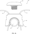
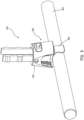
- FIG. 2A is a side elevation view of spinal fixation assembly 100.
- tether clamping assembly 130 comprises two separate pieces, namely, a first or inner coupling piece 140 and a second or outer coupling piece 150 configured to be coupled with the first coupling piece 140.
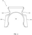
- first and second passages may be defined, respectively, by an inner surface 152 of outer coupling piece 150 and an outer surface 142 of inner coupling piece 140, both of which may be configured to receive separate portions of tether 110 therethrough.
- clamping assembly 130 is self-locking. In other words, by advancing tether 110 through one or both passages, the tension on tether 110 alone results in a tightening, and preferably a locking, of tether 110 in clamping assembly 130.
- clamping assembly 130 is configured such that tether 110 can be clamped and/or locked in clamping assembly 130 so as to allow tether 110 to move through one or both passages in a first direction to lock the tether in place but so as to prevent, or at least substantially prevent, tether 110 from moving through one or both passages in a second direction opposite from the first direction.
- tether 110 may be advanced in an upward direction along both opposing passages, thereby resulting in a tether loop (see FIG. 1 ) that gets smaller, but may be prevented, or at least substantially prevented, from being advanced in a downward direction.
- inner surface(s) 152 of outer coupling piece 150 comprises a plurality of projections 153.
- projections 153 may be defined by a plurality of elongated grooves formed on the inner surface 152 of outer coupling piece 150.
- alternative embodiments are contemplated in which projections 153 may comprise, for example, teeth.
- inner surface 152 of outer coupling piece 150 may, in some embodiments, lack deliberately formed projections and may instead simply comprise a roughened surface.
- Outer surface(s) 142 of inner coupling piece 140 may, in some embodiments, comprise a smooth surface.
- suitable locking may be provided without providing the friction differential described above.
- the embodiment depicted in FIG. 2B also provides for self-locking of tether 110 by virtue of a wedge-locking feature.
- both surfaces be roughened, contoured, and/or formed with frictional features, such as teeth or protrusions, for example.
- opposing surfaces 142/152 may instead both be smooth.
- locking of tether 110 may also result in further locking/tightening of the grip on rod 120.
- outer coupling piece 150 onto inner coupling piece 140
- the tension on tether 110 is increased in the tightening direction by pulling one or both ends of tether 110 through the two opposing passages defined by outer coupling piece 150 and inner coupling piece 140
- the slot 145 created by the inner surface of inner coupling piece 140 is squeezed against the rod 120 more tightly to further lock the tether clamping assembly 130 in place with respect to the rod 120.
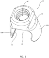
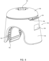
- inner coupling piece 140 may comprise a central opening 147, which may be threaded to receive cap 160. Opening 147 may be configured to be aligned with opening 157 of outer coupling piece 150, as shown in FIG. 5 , upon coupling of outer coupling piece 150 with inner coupling piece 140. Although preferably openings 147 and 157 are configured to be aligned when outer coupling piece 150 is coupled with inner coupling piece 140, opening 157 need not be threaded since threaded opening 147 may engage cap 160 and thereby engage outer coupling piece 150 without itself requiring a direct threaded connection with cap 160.
- Plate 151 may further define opposing tether openings 156A and 156B.
- tether openings 156A and 156B may have a similar matching shape such that the tether may snap into place when properly oriented within the opposing passages, the openings at one end of which are defined by tether openings 156A and 156B.
- opposing slits 159A and 159B may be formed adjacent to plate 151.
- slits 159A and 159B may, together with flanged portion 164 of cap 160, define opposing apertures through which opposing portions of tether 110 may exit from opposing sides of assembly 130.
- FIG. 6 more clearly depicts projections 153 formed within curved inner surface 152A of outer coupling piece 150.
- projections 153 may be formed by cutting elongated, parallel grooves within inner surface 152A.
- the opposing inner surface similarly comprises a plurality of projections 153 to facilitate the self-locking feature of assembly 130.
- cap 160 is an example of secondary means for locking a tether within a rod-coupling assembly. Cap 160 may also serve the function of increasing the lock on the rod and/or tether and/or decreasing the possibility of unwanted loosening/disassembly.
- cap 160 may decrease the possibility of frayed portions of tether 110 from extending down into assembly 130 following cutting of tether 110. This may allow for cutting of tether 110 closer to assembly 130 than may otherwise be possible or desirable.
- self-locking may be provided by the differential friction of the opposing surfaces of one or both tether passages of tether clamping assembly 130.
- cap 160 may be omitted in some embodiments. It is also contemplated that cap 160 may comprise a set screw lacking a flanged portion in some embodiments.
- FIG. 8 is a perspective view of tether clamping assembly 130 showing inner coupling piece 140 fully inserted within outer coupling piece 150 and with cap 160 fully engaged with inner coupling piece 140.
- tether 110 is omitted from FIG. 8 to allow for better viewing of certain features of assembly 130.
- opposing apertures are depicted that may allow for a tether to exit from opposite sides of assembly 130. These apertures are defined by opposing slits 159 (only one of which is visible in FIG. 8 ), respectively, along with a lower surface of flanged portion 164 of cap 160.
- assemblies 100 and/or 130 Another unique feature of assemblies 100 and/or 130 is the ability to loosen the grip/lock/clamp on the tether 110 for readjustment.
- locking of the tether may be accomplished automatically by engaging the tether 110 between the opposing surfaces of the inner and outer coupling pieces and pulling the tether through one or both of the openings in the locking direction, with the optional cap 160 to further enhance this locking of the tether 110 and/or the rod 120.
- This may allow for sequential tightening of various elements of a spinal fixation system without leaving instrumentation in place while moving to a new location within the system, which may also reduce the instrument tray and decrease surgery time.
- notch 154 may be configured to engage a corresponding element of a suitable surgical instrument in order to facilitate this loosening.
- FIG. 9 is a perspective view of an alternative embodiment of a spinal fixation assembly 900.
- assembly 900 would typically comprise a tether, which may be similar to tether 110, that is configured to engage a spinal feature of a patient's spine, such as, in preferred embodiments, looped around the spinal lamina and/or other spinal features, such as the transverse processes of the patient's spine.
- assembly 900 further comprises a tether clamping assembly 930 configured to engage and couple a coupling member, such as a rod 920 or other elongate member, with a tether so as to facilitate coupling of a patient's spine in a desired position without use of pedicle screws or other similar bone-invasive components.
- Tether clamping assembly 930 again comprises two separate elements configured to be coupled with one another so as to clamp one or more (preferably two) portions of a tether therein. More particularly, tether clamping assembly 930 comprises an inner coupling piece 940 configured to be received within an outer coupling piece 950.
- tether clamping assembly 930 differs from tether clamping assembly 130 in several ways.
- inner coupling piece 940 comprises a pair of removable tabs, namely, tabs 970A and 970B.
- Tabs 970A and 970B may be configured to facilitate coupling of outer coupling piece 950 with inner coupling piece 940.
- Tabs 970A and 970B may comprise a plurality of ridges 972.
- Each ridge 972, or each pair of adjacent ridges 972, may serve a distinct purpose during the installation process.
- the top pair of ridges 972 may be used to prevent the outer coupling piece 950 from being removed from assembly 930 during, for example, snapping of the rod 920 into slot 945.
- the middle pair of ridges 972 may prevent the outer coupling piece 950 from dropping all of the way down adjacent to the threaded opening 947 of inner coupling piece 940 to provide spacing for an instrument or a surgeon's hand during this stage.
- the outer coupling piece 950 may be dropped down below the lowest pair of ridges to allow for threading of the tether through opposing passages defined by respective inner surfaces of the outer coupling piece 950 and respective, opposing outer surfaces of the inner coupling piece 940, as previously described. After threading the tether through these passages, the tether may be tensioned about a spinal feature and/or bone.
- tether clamping assembly 930 is configured to provide for self-locking of the tether.
- the tether clamping assembly 930 may be configured such that the tether can be clamped in between opposing surfaces so as to allow the tether to move through the passage(s) in a first direction and lock the tether in place so as to, without any further steps or locking elements/features, at least substantially prevent the tether from moving through the passage(s) in a second direction opposite from the first direction.
- this self-locking feature may be provided by providing a friction differential between the two opposing surfaces through which one or more portions of the tether are received. Preferably, this friction differential is applied such that a movable surface has a greater surface roughness than an opposing non-movable surface.
- opposing inner surface(s) 952 of outer coupling piece 950 comprises a plurality of projections 953, which may be formed by elongated grooves.
- Outer surface(s) 942 of inner coupling piece 940 may, in some embodiments, comprise a smooth surface, or at least a surface lacking projections/grooves.
- surfaces 942 and 952, along with their respective surface features, are therefore another example of means for self-locking a tether within a rod-coupling assembly.
- tabs 970A and 970B may be removed.
- weakened portions 975 such as frangible weakening lines, may be formed in one or both of tabs 970A and 970B.
- Inner coupling piece 940 may also comprise opposing grooves 944 for increasing the flexibility of slot 945 and/or facilitate gripping/engagement by a surgical instrument.
- outer coupling piece 950 comprises an opening 957, which may be configured to receive a threaded projection or another projection from a cap and/or set screw. Opening 957 need not be threaded but may be configured to be aligned with a threaded opening 947 of inner coupling piece 940, as previously described. Outer coupling piece 950 may further comprise one or more notches 954, which may engage a corresponding protruding element of a suitable surgical instrument.
- outer coupling piece 950 differs from outer coupling piece 150 in several respects.
- opposing apertures 956 are formed in outer coupling piece (only one of which is visible in FIG. 11 ) such that a tether (not shown) may extend through the opposing passages previously mentioned and, instead of exiting from an upper surface, may extend through opposing apertures 956 formed in side walls of outer coupling piece 950.
- outer coupling piece 950 comprises opposing slits 959A and 959B formed in an inner surface of outer coupling piece 950.
- Opposing slits 959A and 959B may be configured to partially accommodate ridges 972.
- slits 959A/959B are slightly smaller than ridges 972 such that ridges 972 prevent passage of outer coupling piece 950. Passage of outer coupling piece 950 beyond a given set of ridges 972 may be accomplished by, for example, flexing tabs 970A/970B.
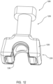
- FIG. 12 depicts yet another alternative embodiment of a spinal fixation assembly 1200.
- assembly 1200 would typically comprise a tether, which may be similar to tether 110, that is configured to engage a spinal feature of a patient's spine, and an elongated fixation member or other coupling member, such as a rod.
- assembly 1200 comprises a tether clamping assembly 1230 comprising two separate elements configured to be coupled with one another so as to clamp one or more (preferably two) portions of a tether and rod or other coupling member therein. More particularly, tether clamping assembly 1230 comprises an inner coupling piece 1240 configured to be received within an outer coupling piece 1250, as previously described.
- tether clamping assembly 1230 differs from the tether clamping assemblies previously described in several ways.
- tether clamping assembly 1230 comprises an alignment insert 1280 that is configured to be received within an opening formed within outer coupling piece 1250 and/or inner coupling piece 1240.
- Alignment insert 1280 may be used to facilitate coupling of outer coupling piece 1250 with inner coupling piece 1240 and/or may be used to facilitate introduction of a set screw (not shown) into inner coupling piece 1240.
- alignment insert 1280 may comprise a tip 1282, which may be configured with a smaller diameter relative to an adjacent body portion 1284 so as to allow for receipt of tip 1282 within one or both of threaded opening 1247 of inner coupling piece 1240 (see FIG. 13 ) and opening 1257 of outer coupling piece 1250 (see FIG. 14 ).
- a handle 1286 Opposite from tip 1282 is a handle 1286, which may be configured to allow a surgeon or practitioner to push alignment insert 1280 into one or more receiving openings to facilitate introduction and coupling of a set screw into threaded opening 1247.
- a central bore 1285 may be formed in alignment insert 1280 and may extend from handle 1286 to tip 1282 to allow for a set screw to travel therethrough.
- a suitable instrument may also be received within bore 1285 to further facilitate such coupling.
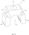
- inner coupling piece 1240 comprises a pair of opposing outer surfaces, namely surfaces 1242A and 1242B.
- surfaces 1242A and 1242B may be configured to define one side of a passage for receipt of a tether (not shown) therethrough.
- surfaces 1242A and 1242B are preferably smooth, or at least having a surface roughness that is less than that of the opposing surface(s), which may be defined by an inner surface or surfaces of outer coupling piece 1250.
- inner coupling piece 1240 may comprise a slot 1245 that is shaped to match, or at least substantially match, the shape of the outer surface of a rod such that the rod may be firmly engaged/gripped by slot 1245.
- slot 1245 may comprise a plurality of teeth (not shown) or a contoured and/or roughened surface to further facilitate a firm engagement between the rod and inner coupling piece 1240.
- Inner coupling piece 1240 further comprises a pair of opposing grooves, namely, grooves 1244A and 1244B, which may increase the flexibility of slot 1245 to allow for receipt of a rod therein by way of a snap-fit connection.
- grooves 1244A and 1244B comprise slits that terminate adjacent to slot 1245.
- outer coupling piece 1250 A perspective view of outer coupling piece 1250 is shown in FIG. 14 .
- outer coupling piece 1250 like inner coupling piece 1240, may comprise a slot 1255 that may be aligned with slot 1245 such that a rod (not shown) or another coupling member may extend through a slot defined by slots 1245 and 1255.
- opposing apertures 1256A and 1256B are formed in outer coupling piece 1250 such that a tether (not shown) may extend through the opposing passages previously mentioned and ultimately extend through opposing apertures 1256A and 1256B.
- Apertures 1256A and 1256B are formed in opposing shelves 1259A and 1259B of outer coupling piece 1250.
- Shelves 1259A and 1259B may be configured to be aligned, or at least substantially aligned, with the top surface of inner coupling piece 1240 upon fully coupling outer coupling piece 1250 with inner coupling piece 1240.
- outer coupling piece 1250 further comprises two internal surfaces each having a plurality of projections 1253, which may, in some embodiments, be defined by a series of parallel grooves, as previously described. These surfaces, together with outer surfaces 1242A and 1242B of inner coupling piece 1240, define two separate passages for receipt of opposing portions of a tether therethrough, as also previously described.
- the opposing surfaces that define these two passages, along with their respective surface features, are therefore another example of means for self-locking a tether within a rod-coupling assembly.
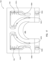
- FIGS. 16-18 depict still another embodiment of a tether clamping assembly 1630 that may be used in connection with a fixation assembly, such as a spinal fixation assembly.
- Tether clamping assembly 1630 is configured to receive two portions of a tether (not shown) therethrough so as to define a loop and tighten the loop around a spinal feature or other anatomical feature, as previously discussed.
- tether clamping assembly 1630 differs from the other coupling assemblies described herein in that tether clamping assembly 1630 is defined by a unitary structure rather than two separate structures coupled together. More particularly, tether clamping assembly 1630 comprises an internal structure defined by two locking members 1651A and 1651B.
- Locking members 1651A and 1651B are movably (in the depicted embodiment, pivotably) positioned in respective internal chambers so as to define empty spaces on either side. More particularly, locking members 1651A and 1651B are positioned in between respective inner spaces 1657A/1657B and outer spaces 1659A/1659B. In the depicted embodiment, opposing tether receiving paths are defined by outer spaces 1659A/1659B, as best seen in the cross-sectional view of FIG. 18 .
- Respective outer surfaces of locking members 1651A and 1651B may comprise a plurality of projections 1653, or may otherwise be surface roughened relative to the opposing inner surfaces 1642A and 1642B.
- both passages of coupling mechanism 1630 are configured to be self-locking with respect to tether portions received therethrough.
- the tether portions upon extending respective tether portions through these passages and applying tension in the upward direction (relative to the orientation in FIGS. 16 and 17 ), the tether portions retain the applied tension and are prevented, or at least inhibited, from being pulled in the opposite, downward direction.
- the opposing surfaces defining passages 1659A and 1659B, along with their respective surface features, are therefore another example of means for self-locking a tether within a rod-coupling assembly.
- first passage 1659A for receiving a first portion of a tether, such as a flexible band, therethrough.
- surface 1642B together with the surface upon which projections 1653B are formed, define a second passage 1659B for receiving a second portion of the tether therethrough.
- These passages have openings on opposite ends of tether clamping assembly 1630, namely, upper openings 1656A and 1656B and respective lower openings 1652A and 1652B.
- locking members 1651A and 1651B are pivotably movable within their respective chambers.
- outer spaces 1659A/1659B may be configured, respectively, to allow locking members 1651A and 1651B to be resiliently biased towards the center of tether clamping assembly 1630 by a predetermined distance.
- the width of the opposing passages defined in part by locking members 1651A and 1651B may be slightly increased as locking members 1651A and 1651B pivot in this manner.
- respective base portions of locking members 1651A and 1651B may be narrowed to provide the flexibility to allow for this pivoting/movement.
- locking members 1651A and 1651B are movable, as previously discussed, preferably the friction differential between the opposing surfaces defining the passages are applied such that the surface on locking members 1651A and 1651B (the movable surfaces) have a greater surface roughness than the opposing non-movable surfaces.
- the projections 1653 may only be formed on these surfaces of locking members 1651A and 1651B and not on the opposing inner surfaces 1642A and 1642B of the inner chamber of tether clamping assembly 1630.
- Tether clamping assembly 1630 further comprises release mechanisms to allow the self-locking feature to be unlocked.
- these release mechanisms comprise tether clamping assembly openings 1658A and 1658B which are positioned to allow access to respective locking member openings 1654A and 1654B formed in upper surfaces of locking members 1651A and 1651B.
- openings 1654A and 1654B may be configured to receive portions of a suitable instrument, such as prongs.
- this may allow a user to, for example, squeeze the locking members 1651A and 1651B towards one another and thereby release their respective locks on the tether portions extending through the tether passages extending between upper openings 1656A and 1656B and respective lower openings 1652A and 1652B.
- only one of the locking member openings 1654A and 1654B may be engaged, if desired, in order to only unlock the locking/clamping of tether clamping assembly 1630 on one tether portion instead of both portions extending through tether clamping assembly 1630.
- a tether such as in some such implementations a flexible band
- an anatomical feature such as around a spinal transverse process or spinal lamina
- An elongate member such as a rigid rod, may be coupled with a clamping assembly, such as any of the various clamping assemblies disclosed herein.
- a first end of the tether may then be fed through a first passage of the clamping assembly.
- the first passage may be defined by a first pair of opposing surfaces having distinct surface roughnesses.
- a movable surface (relative to the elongate member) may comprise a greater surface roughness that an opposing non-movable surface.
- the movable surface may be formed with a plurality of grooves and/or projections to increase the surface roughness and/or grip on the tether.
- a second end of the flexible tether opposite from the first end may also be fed through a second passage, which may be defined by a second pair of opposing surfaces also having distinct surface roughnesses.
- the first end of the flexible tether may be fed through the first passage and/or the second end of the flexible tether may be fed through the second passage to automatically lock the flexible tether in place about the anatomical feature without the use of a secondary locking feature, such as a locking cap, set screw, or the like, to prevent a size of the loop from increasing.
- the clamping assembly may comprise an inner coupling piece and an outer coupling piece configured to receive the inner coupling piece.
- the first passage and the second passage may be at least partially defined by an inner surface of the outer coupling piece and an outer surface of the inner coupling piece.
- the clamping assembly may also be unlocked following the self-locking procedure.
- a user may unlock one or both tether portions using a means for unlocking a self-locking tether, such as the locking member openings 1654A and 1654B formed in upper surfaces of locking members 1651A and 1651B, for example. This may allow for readjustment or loosening of a tether clamping assembly following self-locking of the tether within the assembly.
Landscapes
- Health & Medical Sciences (AREA)
- Orthopedic Medicine & Surgery (AREA)
- Life Sciences & Earth Sciences (AREA)
- Neurology (AREA)
- Surgery (AREA)
- Heart & Thoracic Surgery (AREA)
- Engineering & Computer Science (AREA)
- Biomedical Technology (AREA)
- Nuclear Medicine, Radiotherapy & Molecular Imaging (AREA)
- Medical Informatics (AREA)
- Molecular Biology (AREA)
- Animal Behavior & Ethology (AREA)
- General Health & Medical Sciences (AREA)
- Public Health (AREA)
- Veterinary Medicine (AREA)
- Surgical Instruments (AREA)
Claims (13)
- Wirbelsäulenfixierungsanordnung (100), umfassend:einen Haltegurt (110), der dazu konfiguriert ist, in ein Wirbelsäulenmerkmal der Wirbelsäule eines Patienten einzugreifen, wobei der Haltegurt (110) frei von Verriegelungszähnen ist;ein inneres Kopplungsstück (140), wobei das innere Kopplungsstück (140) einen Schlitz (145) umfasst, der dazu konfiguriert ist, darin eine Stange (120) aufzunehmen und in diese einzugreifen;ein äußeres Kopplungsstück (150), das dazu konfiguriert ist, mit dem inneren Kopplungsstück (140) auf verschachtelte Weise gekoppelt zu sein;einen ersten Durchgang, der dazu konfiguriert ist, einen ersten Abschnitt des Haltegurts (110) aufzunehmen, wobei der erste Durchgang von einer inneren Oberfläche (152) des äußeren Kopplungsstücks (150) und einer äußeren Oberfläche (142) des inneren Kopplungsstücks (140) definiert ist, wobei der erste Durchgang so konfiguriert ist, dass der Haltegurt (110) zwischen der inneren Oberfläche (152) und der äußeren Oberfläche (142) geklemmt werden kann, so dass sich der Haltegurt (110) durch den ersten Durchgang in einer ersten Richtung bewegen und den Haltegurt (110) in Position verriegeln kann, um so zumindest zu verhindern, dass sich der Haltegurt (110) durch den ersten Durchgang in einer zweiten Richtung entgegen der ersten Richtung bewegt.
- Wirbelsäulenfixierungsanordnung (100) nach Anspruch 1, wobei a) der Haltegurt (110) eine rechteckige Form im Querschnitt umfasst und wobei der Haltegurt (110) gegenüberliegende Oberflächen umfasst, die zumindest im Wesentlichen in der Rauheit gleichmäßig sind; oder b) der Haltegurt (110) eine rechteckige Form im Querschnitt umfasst und wobei der Haltegurt (110) gegenüberliegende Oberflächen umfasst, die zumindest im Wesentlichen in der Rauheit gleichmäßig sind und wobei die gegenüberliegenden Oberflächen des Haltegurts (110) glatt sind.
- Wirbelsäulenfixierungsanordnung (100) nach Anspruch 1, ferner umfassend a) einen zweiten Durchgang, die dazu konfiguriert ist, einen zweiten Abschnitt des Haltegurts (110) aufzunehmen, um so eine Haltegurtschlaufe zum Eingreifen in das Wirbelsäulenmerkmal zu definieren; oder b) einen zweiten Durchgang, der dazu konfiguriert ist, einen zweiten Abschnitt des Haltegurts (110) aufzunehmen, um so eine Haltegurtschlaufe zum Eingreifen in das Wirbelsäulenmerkmal zu definieren und wobei die innere Oberfläche (152) eine Oberflächenrauheit umfasst, die größer als eine Oberflächenrauheit der äußeren Oberfläche (142) ist, wobei der zweite Durchgang von einer inneren Oberfläche (152) des äußeren Kopplungsstücks (150) und einer äußeren Oberfläche (142) des inneren Kopplungsstücks (140) definiert ist und wobei die innere Oberfläche (152) des zweiten Durchgangs eine Oberflächenrauheit umfasst, die größer als eine Oberflächenrauheit der äußeren Oberfläche (142) des zweiten Durchgangs ist.
- Wirbelsäulenfixierungsanordnung (100) nach Anspruch 1, wobei die innere Oberfläche (152) eine Vielzahl von Vorsprüngen (153) umfasst, die dazu konfiguriert sind, in den Haltegurt (110) einzugreifen.
- Wirbelsäulenfixierungsanordnung (100) nach Anspruch 4, wobei die äußere Oberfläche (142) glatt ist.
- Wirbelsäulenfixierungsanordnung (100) nach Anspruch 4, wobei jeder der Vielzahl von Vorsprüngen (153) von einer Vielzahl von länglichen Nuten (144) definiert ist, die auf der inneren Oberfläche (140) gebildet sind.
- Wirbelsäulenfixierungsanordnung (100) nach Anspruch 1, wobei sich die innere Oberfläche (152) und die äußere Oberfläche (142) relativ zu einer zentralen Achse des inneren Kopplungsstücks (140) verjüngen, um so eine Keilverriegelung zum Klemmen des Haltegurts (110) dazwischen zu schaffen.
- Haltegurtklemmanordnung, umfassend:einen Haltegurt (110), der dazu konfiguriert ist, in einen Knochen einzugreifen;ein inneres Kopplungsstück (140), wobei das innere Kopplungsstück (140) einen Schlitz (145) umfasst, der dazu konfiguriert ist, darin eine Stange (120) aufzunehmen und in diese einzugreifen;ein äußeres Kopplungsstück (150), das dazu konfiguriert ist, das innere Kopplungsstück (140) auf verschachtelte Weise aufzunehmen; undeinen ersten Durchgang, der zumindest teilweise von einer inneren Oberfläche (152) des äußeren Kopplungsstücks (150) und einer äußeren Oberfläche (142) des inneren Kopplungsstücks (140) definiert und dazu konfiguriert ist, den Haltegurt (110) hindurch aufzunehmen,wobei der erste Durchgang so konfiguriert ist, dass der Haltegurt (110) zwischen der inneren Oberfläche (152) und der äußeren Oberfläche (142) geklemmt werden kann, so dass sich der Haltegurt (110) durch den ersten Durchgang in einer ersten Richtung bewegen und den Haltegurt (110) in Position verriegeln kann, um so zumindest im Wesentlichen zu verhindern, dass sich der Haltegurt (110) durch den ersten Durchgang in einer zweiten Richtung entgegen der ersten Richtung bewegt, undwobei zumindest eine der inneren Oberfläche (152) und der äußeren Oberfläche (142) eine Vielzahl von Vorsprüngen (153) umfasst, die dazu konfiguriert sind, in den Haltegurt (110) einzugreifen.
- Haltegurtklemmanordnung nach Anspruch 8, wobei nur eine der inneren Oberfläche (152) und der äußeren Oberfläche (142) eine Vielzahl von Vorsprüngen (153) umfasst, die dazu konfiguriert sind, in den Haltegurt (110) einzugreifen.
- Haltegurtklemmanordnung nach Anspruch 8, ferner umfassend einen zweiten Durchgang, der zumindest teilweise von einer inneren Oberfläche (152) des äußeren Kopplungsstücks (150) und einer äußeren Oberfläche (142) des inneren Kopplungsstücks (140) definiert und dazu konfiguriert ist, einen zweiten Abschnitt des Haltegurts (110) hindurch aufzunehmen, um so eine Haltegurtschlaufe zum Eingreifen in den Knochen zu definieren.
- Haltegurtklemmanordnung nach Anspruch 10, wobei der zweite Durchgang so konfiguriert ist, dass der Haltegurt (110) zwischen der inneren Oberfläche (152) des zweiten Durchgangs und der äußeren Oberfläche (142) des zweiten Durchgangs geklemmt werden kann, so dass sich der Haltegurt (110) durch den zweiten Durchgang in einer ersten Richtung bewegen und den Haltegurt (110) in Position verriegeln kann, um so zumindest im Wesentlichen zu verhindern, dass sich der Haltegurt (110) durch den zweiten Durchgang in einer zweiten Richtung entgegen der ersten Richtung bewegt.
- Haltegurtklemmanordnung nach Anspruch 8, ferner umfassend eine Kappe (160), die dazu konfiguriert ist, in das innere Kopplungsstück (140) einzugreifen.
- Haltegurtklemmanordnung nach Anspruch 12, wobei die Kappe (160) ein Gewinde aufweist, wobei die Kappe (160) dazu konfiguriert ist, in eine auf dem inneren Kopplungsstück (140) gebildete Gewindeöffnung (147) einzugreifen, und wobei die Kappe (160) einen Flansch (164) umfasst, der dazu konfiguriert ist, in das äußere Kopplungsstück (150) einzugreifen.
Applications Claiming Priority (1)
| Application Number | Priority Date | Filing Date | Title |
|---|---|---|---|
| PCT/US2019/015698 WO2020159483A1 (en) | 2019-01-29 | 2019-01-29 | Tether clamping assemblies and related methods and apparatus |
Publications (3)
| Publication Number | Publication Date |
|---|---|
| EP3917420A1 EP3917420A1 (de) | 2021-12-08 |
| EP3917420A4 EP3917420A4 (de) | 2022-09-28 |
| EP3917420B1 true EP3917420B1 (de) | 2025-04-02 |
Family
ID=71840492
Family Applications (1)
| Application Number | Title | Priority Date | Filing Date |
|---|---|---|---|
| EP19912377.9A Active EP3917420B1 (de) | 2019-01-29 | 2019-01-29 | Haltegurtklemmanordnungen zur wirbelsäulenfixierung |
Country Status (3)
| Country | Link |
|---|---|
| EP (1) | EP3917420B1 (de) |
| JP (1) | JP7065116B2 (de) |
| WO (1) | WO2020159483A1 (de) |
Family Cites Families (7)
| Publication number | Priority date | Publication date | Assignee | Title |
|---|---|---|---|---|
| US5356412A (en) * | 1992-10-09 | 1994-10-18 | United States Surgical Corporation | Sternum buckle with rotational engagement and method of closure |
| CA2405023A1 (en) * | 2000-10-24 | 2002-05-16 | The Spineology Group, Llc | Tension band clip |
| EP2279707A1 (de) * | 2009-07-31 | 2011-02-02 | Zimmer Spine | Knochenfixierungssystem |
| FR2954905B1 (fr) * | 2010-01-06 | 2012-12-28 | Implanet | Dispositif de fixation vertebrale |
| EP2465457B1 (de) * | 2010-12-16 | 2014-04-30 | Zimmer Spine | Vorrichtung zum Sichern eines Ligaturfadens an einer Knochenstruktur |
| US9433441B2 (en) * | 2013-03-05 | 2016-09-06 | Globus Medical, Inc. | Elastic member clamps |
| US9924976B2 (en) * | 2015-09-24 | 2018-03-27 | Warsaw Orthopedic, Inc. | Spinal implant system and method |
-
2019
- 2019-01-29 JP JP2019562413A patent/JP7065116B2/ja active Active
- 2019-01-29 WO PCT/US2019/015698 patent/WO2020159483A1/en not_active Ceased
- 2019-01-29 EP EP19912377.9A patent/EP3917420B1/de active Active
Also Published As
| Publication number | Publication date |
|---|---|
| WO2020159483A1 (en) | 2020-08-06 |
| JP7065116B2 (ja) | 2022-05-11 |
| EP3917420A1 (de) | 2021-12-08 |
| EP3917420A4 (de) | 2022-09-28 |
| JP2021514687A (ja) | 2021-06-17 |
Similar Documents
| Publication | Publication Date | Title |
|---|---|---|
| US11857221B2 (en) | Nesting tether clamping assemblies and related methods and apparatus | |
| US11051857B2 (en) | Tether clamping assemblies and related methods and apparatus | |
| US12178482B2 (en) | Orthopaedic fixation devices, systems and methods | |
| US10588667B2 (en) | Top and bottom loadable bone screw assembly with direct pivotal engagement between shank head and receiver | |
| US20260033870A1 (en) | Polyaxial bone anchoring device and system including an instrument and a polyaxial bone anchoring device | |
| EP1365693B1 (de) | Vorrichtung zur fixierung des brustbeins | |
| US8740946B2 (en) | Bone anchor with locking cap and method of spinal fixation | |
| EP2094175B1 (de) | Wirbelsäulenkreuzkonnektoren | |
| US20100004694A1 (en) | Screw assembly | |
| EP4025143B1 (de) | Knochenfixierungssystem mit befestigungselementen und demontagewerkzeug zum entkoppeln der befestigungselemente | |
| WO1999009904A1 (en) | Surgical cable system and method | |
| JP7312575B2 (ja) | 多軸骨固着装置、および、器具と多軸骨固着装置とのシステム | |
| US10070895B2 (en) | Dual tulip assembly | |
| US20240315738A1 (en) | Vertebral implant for dynamic stabilization | |
| WO2020159483A1 (en) | Tether clamping assemblies and related methods and apparatus | |
| JP7397141B2 (ja) | バンドクランプインプラント及び張力付与器具を使用する外科手術のためのシステム及び方法 | |
| EP3352694B1 (de) | Knochenfixiervorrichtungen mit einer verriegelungsfunktion | |
| WO2022152761A1 (en) | Spinal fixation system | |
| EP3322367B1 (de) | Kabelfixiervorrichtung und instrumente | |
| HK1059870B (en) | Sternum fixation device |
Legal Events
| Date | Code | Title | Description |
|---|---|---|---|
| STAA | Information on the status of an ep patent application or granted ep patent |
Free format text: STATUS: THE INTERNATIONAL PUBLICATION HAS BEEN MADE |
|
| PUAI | Public reference made under article 153(3) epc to a published international application that has entered the european phase |
Free format text: ORIGINAL CODE: 0009012 |
|
| STAA | Information on the status of an ep patent application or granted ep patent |
Free format text: STATUS: REQUEST FOR EXAMINATION WAS MADE |
|
| 17P | Request for examination filed |
Effective date: 20210720 |
|
| AK | Designated contracting states |
Kind code of ref document: A1 Designated state(s): AL AT BE BG CH CY CZ DE DK EE ES FI FR GB GR HR HU IE IS IT LI LT LU LV MC MK MT NL NO PL PT RO RS SE SI SK SM TR |
|
| DAV | Request for validation of the european patent (deleted) | ||
| DAX | Request for extension of the european patent (deleted) | ||
| A4 | Supplementary search report drawn up and despatched |
Effective date: 20220826 |
|
| RIC1 | Information provided on ipc code assigned before grant |
Ipc: A61B 90/00 20160101ALI20220822BHEP Ipc: A61B 17/70 20060101AFI20220822BHEP |
|
| GRAP | Despatch of communication of intention to grant a patent |
Free format text: ORIGINAL CODE: EPIDOSNIGR1 |
|
| STAA | Information on the status of an ep patent application or granted ep patent |
Free format text: STATUS: GRANT OF PATENT IS INTENDED |
|
| INTG | Intention to grant announced |
Effective date: 20241024 |
|
| GRAS | Grant fee paid |
Free format text: ORIGINAL CODE: EPIDOSNIGR3 |
|
| GRAA | (expected) grant |
Free format text: ORIGINAL CODE: 0009210 |
|
| STAA | Information on the status of an ep patent application or granted ep patent |
Free format text: STATUS: THE PATENT HAS BEEN GRANTED |
|
| AK | Designated contracting states |
Kind code of ref document: B1 Designated state(s): AL AT BE BG CH CY CZ DE DK EE ES FI FR GB GR HR HU IE IS IT LI LT LU LV MC MK MT NL NO PL PT RO RS SE SI SK SM TR |
|
| P01 | Opt-out of the competence of the unified patent court (upc) registered |
Free format text: CASE NUMBER: APP_9169/2025 Effective date: 20250224 |
|
| REG | Reference to a national code |
Ref country code: GB Ref legal event code: FG4D |
|
| REG | Reference to a national code |
Ref country code: CH Ref legal event code: EP |
|
| REG | Reference to a national code |
Ref country code: DE Ref legal event code: R096 Ref document number: 602019068263 Country of ref document: DE |
|
| REG | Reference to a national code |
Ref country code: IE Ref legal event code: FG4D |
|
| REG | Reference to a national code |
Ref country code: NL Ref legal event code: MP Effective date: 20250402 |
|
| PG25 | Lapsed in a contracting state [announced via postgrant information from national office to epo] |
Ref country code: NL Free format text: LAPSE BECAUSE OF FAILURE TO SUBMIT A TRANSLATION OF THE DESCRIPTION OR TO PAY THE FEE WITHIN THE PRESCRIBED TIME-LIMIT Effective date: 20250402 |
|
| REG | Reference to a national code |
Ref country code: AT Ref legal event code: MK05 Ref document number: 1780524 Country of ref document: AT Kind code of ref document: T Effective date: 20250402 |
|
| PG25 | Lapsed in a contracting state [announced via postgrant information from national office to epo] |
Ref country code: FI Free format text: LAPSE BECAUSE OF FAILURE TO SUBMIT A TRANSLATION OF THE DESCRIPTION OR TO PAY THE FEE WITHIN THE PRESCRIBED TIME-LIMIT Effective date: 20250402 Ref country code: ES Free format text: LAPSE BECAUSE OF FAILURE TO SUBMIT A TRANSLATION OF THE DESCRIPTION OR TO PAY THE FEE WITHIN THE PRESCRIBED TIME-LIMIT Effective date: 20250402 Ref country code: PT Free format text: LAPSE BECAUSE OF FAILURE TO SUBMIT A TRANSLATION OF THE DESCRIPTION OR TO PAY THE FEE WITHIN THE PRESCRIBED TIME-LIMIT Effective date: 20250804 |
|
| REG | Reference to a national code |
Ref country code: LT Ref legal event code: MG9D |
|
| PG25 | Lapsed in a contracting state [announced via postgrant information from national office to epo] |
Ref country code: GR Free format text: LAPSE BECAUSE OF FAILURE TO SUBMIT A TRANSLATION OF THE DESCRIPTION OR TO PAY THE FEE WITHIN THE PRESCRIBED TIME-LIMIT Effective date: 20250703 Ref country code: NO Free format text: LAPSE BECAUSE OF FAILURE TO SUBMIT A TRANSLATION OF THE DESCRIPTION OR TO PAY THE FEE WITHIN THE PRESCRIBED TIME-LIMIT Effective date: 20250702 |
|
| PG25 | Lapsed in a contracting state [announced via postgrant information from national office to epo] |
Ref country code: PL Free format text: LAPSE BECAUSE OF FAILURE TO SUBMIT A TRANSLATION OF THE DESCRIPTION OR TO PAY THE FEE WITHIN THE PRESCRIBED TIME-LIMIT Effective date: 20250402 |
|
| PG25 | Lapsed in a contracting state [announced via postgrant information from national office to epo] |
Ref country code: BG Free format text: LAPSE BECAUSE OF FAILURE TO SUBMIT A TRANSLATION OF THE DESCRIPTION OR TO PAY THE FEE WITHIN THE PRESCRIBED TIME-LIMIT Effective date: 20250402 |
|
| PG25 | Lapsed in a contracting state [announced via postgrant information from national office to epo] |
Ref country code: HR Free format text: LAPSE BECAUSE OF FAILURE TO SUBMIT A TRANSLATION OF THE DESCRIPTION OR TO PAY THE FEE WITHIN THE PRESCRIBED TIME-LIMIT Effective date: 20250402 |
|
| PG25 | Lapsed in a contracting state [announced via postgrant information from national office to epo] |
Ref country code: AT Free format text: LAPSE BECAUSE OF FAILURE TO SUBMIT A TRANSLATION OF THE DESCRIPTION OR TO PAY THE FEE WITHIN THE PRESCRIBED TIME-LIMIT Effective date: 20250402 |
|
| PG25 | Lapsed in a contracting state [announced via postgrant information from national office to epo] |
Ref country code: RS Free format text: LAPSE BECAUSE OF FAILURE TO SUBMIT A TRANSLATION OF THE DESCRIPTION OR TO PAY THE FEE WITHIN THE PRESCRIBED TIME-LIMIT Effective date: 20250702 |
|
| PG25 | Lapsed in a contracting state [announced via postgrant information from national office to epo] |
Ref country code: IS Free format text: LAPSE BECAUSE OF FAILURE TO SUBMIT A TRANSLATION OF THE DESCRIPTION OR TO PAY THE FEE WITHIN THE PRESCRIBED TIME-LIMIT Effective date: 20250802 |
|
| PG25 | Lapsed in a contracting state [announced via postgrant information from national office to epo] |
Ref country code: LV Free format text: LAPSE BECAUSE OF FAILURE TO SUBMIT A TRANSLATION OF THE DESCRIPTION OR TO PAY THE FEE WITHIN THE PRESCRIBED TIME-LIMIT Effective date: 20250402 |
|
| REG | Reference to a national code |
Ref country code: DE Ref legal event code: R097 Ref document number: 602019068263 Country of ref document: DE |
|
| PG25 | Lapsed in a contracting state [announced via postgrant information from national office to epo] |
Ref country code: DK Free format text: LAPSE BECAUSE OF FAILURE TO SUBMIT A TRANSLATION OF THE DESCRIPTION OR TO PAY THE FEE WITHIN THE PRESCRIBED TIME-LIMIT Effective date: 20250402 Ref country code: SM Free format text: LAPSE BECAUSE OF FAILURE TO SUBMIT A TRANSLATION OF THE DESCRIPTION OR TO PAY THE FEE WITHIN THE PRESCRIBED TIME-LIMIT Effective date: 20250402 |
|
| PG25 | Lapsed in a contracting state [announced via postgrant information from national office to epo] |
Ref country code: CZ Free format text: LAPSE BECAUSE OF FAILURE TO SUBMIT A TRANSLATION OF THE DESCRIPTION OR TO PAY THE FEE WITHIN THE PRESCRIBED TIME-LIMIT Effective date: 20250402 |
|
| PG25 | Lapsed in a contracting state [announced via postgrant information from national office to epo] |
Ref country code: EE Free format text: LAPSE BECAUSE OF FAILURE TO SUBMIT A TRANSLATION OF THE DESCRIPTION OR TO PAY THE FEE WITHIN THE PRESCRIBED TIME-LIMIT Effective date: 20250402 |
|
| PG25 | Lapsed in a contracting state [announced via postgrant information from national office to epo] |
Ref country code: SK Free format text: LAPSE BECAUSE OF FAILURE TO SUBMIT A TRANSLATION OF THE DESCRIPTION OR TO PAY THE FEE WITHIN THE PRESCRIBED TIME-LIMIT Effective date: 20250402 Ref country code: RO Free format text: LAPSE BECAUSE OF FAILURE TO SUBMIT A TRANSLATION OF THE DESCRIPTION OR TO PAY THE FEE WITHIN THE PRESCRIBED TIME-LIMIT Effective date: 20250402 |
|
| PG25 | Lapsed in a contracting state [announced via postgrant information from national office to epo] |
Ref country code: IT Free format text: LAPSE BECAUSE OF FAILURE TO SUBMIT A TRANSLATION OF THE DESCRIPTION OR TO PAY THE FEE WITHIN THE PRESCRIBED TIME-LIMIT Effective date: 20250402 |
|
| PLBE | No opposition filed within time limit |
Free format text: ORIGINAL CODE: 0009261 |
|
| STAA | Information on the status of an ep patent application or granted ep patent |
Free format text: STATUS: NO OPPOSITION FILED WITHIN TIME LIMIT |
|
| REG | Reference to a national code |
Ref country code: CH Ref legal event code: L10 Free format text: ST27 STATUS EVENT CODE: U-0-0-L10-L00 (AS PROVIDED BY THE NATIONAL OFFICE) Effective date: 20260211 |
|
| 26N | No opposition filed |
Effective date: 20260105 |
|
| PGFP | Annual fee paid to national office [announced via postgrant information from national office to epo] |
Ref country code: GB Payment date: 20260227 Year of fee payment: 8 |
|
| PGFP | Annual fee paid to national office [announced via postgrant information from national office to epo] |
Ref country code: DE Payment date: 20260227 Year of fee payment: 8 |
|
| PGFP | Annual fee paid to national office [announced via postgrant information from national office to epo] |
Ref country code: FR Payment date: 20260225 Year of fee payment: 8 |