EP3917471B1 - Structure de pansement déchirable - Google Patents
Structure de pansement déchirable Download PDFInfo
- Publication number
- EP3917471B1 EP3917471B1 EP20703343.2A EP20703343A EP3917471B1 EP 3917471 B1 EP3917471 B1 EP 3917471B1 EP 20703343 A EP20703343 A EP 20703343A EP 3917471 B1 EP3917471 B1 EP 3917471B1
- Authority
- EP
- European Patent Office
- Prior art keywords
- layer
- openings
- dressing material
- film
- slits
- Prior art date
- Legal status (The legal status is an assumption and is not a legal conclusion. Google has not performed a legal analysis and makes no representation as to the accuracy of the status listed.)
- Active
Links
Images


Classifications
-
- A—HUMAN NECESSITIES
- A61—MEDICAL OR VETERINARY SCIENCE; HYGIENE
- A61F—FILTERS IMPLANTABLE INTO BLOOD VESSELS; PROSTHESES; DEVICES PROVIDING PATENCY TO, OR PREVENTING COLLAPSING OF, TUBULAR STRUCTURES OF THE BODY, e.g. STENTS; ORTHOPAEDIC, NURSING OR CONTRACEPTIVE DEVICES; FOMENTATION; TREATMENT OR PROTECTION OF EYES OR EARS; BANDAGES, DRESSINGS OR ABSORBENT PADS; FIRST-AID KITS
- A61F13/00—Bandages or dressings; Absorbent pads
- A61F13/02—Adhesive bandages or dressings
- A61F13/0203—Adhesive bandages or dressings with fluid retention members
- A61F13/0206—Adhesive bandages or dressings with fluid retention members with absorbent fibrous layers, e.g. woven or non-woven absorbent pads or island dressings
-
- A—HUMAN NECESSITIES
- A61—MEDICAL OR VETERINARY SCIENCE; HYGIENE
- A61F—FILTERS IMPLANTABLE INTO BLOOD VESSELS; PROSTHESES; DEVICES PROVIDING PATENCY TO, OR PREVENTING COLLAPSING OF, TUBULAR STRUCTURES OF THE BODY, e.g. STENTS; ORTHOPAEDIC, NURSING OR CONTRACEPTIVE DEVICES; FOMENTATION; TREATMENT OR PROTECTION OF EYES OR EARS; BANDAGES, DRESSINGS OR ABSORBENT PADS; FIRST-AID KITS
- A61F13/00—Bandages or dressings; Absorbent pads
- A61F13/05—Bandages or dressings; Absorbent pads specially adapted for use with sub-pressure or over-pressure therapy, wound drainage or wound irrigation, e.g. for use with negative-pressure wound therapy [NPWT]
-
- A—HUMAN NECESSITIES
- A61—MEDICAL OR VETERINARY SCIENCE; HYGIENE
- A61L—METHODS OR APPARATUS FOR STERILISING MATERIALS OR OBJECTS IN GENERAL; DISINFECTION, STERILISATION OR DEODORISATION OF AIR; CHEMICAL ASPECTS OF BANDAGES, DRESSINGS, ABSORBENT PADS OR SURGICAL ARTICLES; MATERIALS FOR BANDAGES, DRESSINGS, ABSORBENT PADS OR SURGICAL ARTICLES
- A61L15/00—Chemical aspects of, or use of materials for, bandages, dressings or absorbent pads
- A61L15/16—Bandages, dressings or absorbent pads for physiological fluids such as urine or blood, e.g. sanitary towels, tampons
- A61L15/22—Bandages, dressings or absorbent pads for physiological fluids such as urine or blood, e.g. sanitary towels, tampons containing macromolecular materials
- A61L15/26—Macromolecular compounds obtained otherwise than by reactions only involving carbon-to-carbon unsaturated bonds; Derivatives thereof
-
- A—HUMAN NECESSITIES
- A61—MEDICAL OR VETERINARY SCIENCE; HYGIENE
- A61L—METHODS OR APPARATUS FOR STERILISING MATERIALS OR OBJECTS IN GENERAL; DISINFECTION, STERILISATION OR DEODORISATION OF AIR; CHEMICAL ASPECTS OF BANDAGES, DRESSINGS, ABSORBENT PADS OR SURGICAL ARTICLES; MATERIALS FOR BANDAGES, DRESSINGS, ABSORBENT PADS OR SURGICAL ARTICLES
- A61L15/00—Chemical aspects of, or use of materials for, bandages, dressings or absorbent pads
- A61L15/16—Bandages, dressings or absorbent pads for physiological fluids such as urine or blood, e.g. sanitary towels, tampons
- A61L15/42—Use of materials characterised by their function or physical properties
- A61L15/425—Porous materials, e.g. foams or sponges
-
- A—HUMAN NECESSITIES
- A61—MEDICAL OR VETERINARY SCIENCE; HYGIENE
- A61M—DEVICES FOR INTRODUCING MEDIA INTO, OR ONTO, THE BODY; DEVICES FOR TRANSDUCING BODY MEDIA OR FOR TAKING MEDIA FROM THE BODY; DEVICES FOR PRODUCING OR ENDING SLEEP OR STUPOR
- A61M1/00—Suction or pumping devices for medical purposes; Devices for carrying-off, for treatment of, or for carrying-over, body-liquids; Drainage systems
- A61M1/90—Negative pressure wound therapy devices, i.e. devices for applying suction to a wound to promote healing, e.g. including a vacuum dressing
- A61M1/91—Suction aspects of the dressing
- A61M1/915—Constructional details of the pressure distribution manifold
-
- A—HUMAN NECESSITIES
- A61—MEDICAL OR VETERINARY SCIENCE; HYGIENE
- A61F—FILTERS IMPLANTABLE INTO BLOOD VESSELS; PROSTHESES; DEVICES PROVIDING PATENCY TO, OR PREVENTING COLLAPSING OF, TUBULAR STRUCTURES OF THE BODY, e.g. STENTS; ORTHOPAEDIC, NURSING OR CONTRACEPTIVE DEVICES; FOMENTATION; TREATMENT OR PROTECTION OF EYES OR EARS; BANDAGES, DRESSINGS OR ABSORBENT PADS; FIRST-AID KITS
- A61F13/00—Bandages or dressings; Absorbent pads
- A61F2013/00089—Wound bandages
- A61F2013/00357—Wound bandages implanted wound fillings or covers
-
- A—HUMAN NECESSITIES
- A61—MEDICAL OR VETERINARY SCIENCE; HYGIENE
- A61M—DEVICES FOR INTRODUCING MEDIA INTO, OR ONTO, THE BODY; DEVICES FOR TRANSDUCING BODY MEDIA OR FOR TAKING MEDIA FROM THE BODY; DEVICES FOR PRODUCING OR ENDING SLEEP OR STUPOR
- A61M1/00—Suction or pumping devices for medical purposes; Devices for carrying-off, for treatment of, or for carrying-over, body-liquids; Drainage systems
- A61M1/90—Negative pressure wound therapy devices, i.e. devices for applying suction to a wound to promote healing, e.g. including a vacuum dressing
- A61M1/92—Negative pressure wound therapy devices, i.e. devices for applying suction to a wound to promote healing, e.g. including a vacuum dressing with liquid supply means
-
- A—HUMAN NECESSITIES
- A61—MEDICAL OR VETERINARY SCIENCE; HYGIENE
- A61M—DEVICES FOR INTRODUCING MEDIA INTO, OR ONTO, THE BODY; DEVICES FOR TRANSDUCING BODY MEDIA OR FOR TAKING MEDIA FROM THE BODY; DEVICES FOR PRODUCING OR ENDING SLEEP OR STUPOR
- A61M1/00—Suction or pumping devices for medical purposes; Devices for carrying-off, for treatment of, or for carrying-over, body-liquids; Drainage systems
- A61M1/90—Negative pressure wound therapy devices, i.e. devices for applying suction to a wound to promote healing, e.g. including a vacuum dressing
- A61M1/96—Suction control thereof
Definitions
- the invention set forth in the appended claims relates generally to tissue treatment systems and more particularly, but without limitation, to dressings for tissue treatment.
- Negative-pressure therapy may provide a number of benefits, including migration of epithelial and subcutaneous tissues, improved blood flow, and micro-deformation of tissue at a wound site. Together, these benefits can increase development of granulation tissue and reduce healing times.
- the invention provides a dressing material according to claim 1. Further optional features are provided in dependent claims 2-19.
- the invention also provides a method of manufacturing a dressing material according to claim 20.
- the invention also provides a system for treating a tissue site according to claim 21. Further optional features are provided in claim 22.
- Documents CA 3 065 517 and US 2018/353662 discloses a dressing material.
- FIG 1 is an assembly view of an example of a tissue interface 100 for applying to a tissue site.
- the tissue interface 100 can be generally adapted to partially or fully contact a tissue site. If the tissue site is a wound, for example, the tissue interface 100 may partially or completely fill the wound, or may be placed over the wound.
- the tissue interface 100 may have a first side 105 and a second side 115.
- the tissue interface 100 may include a first layer 110, a second layer 120, and a third layer 130. In some embodiments, the first layer 110, the second layer 120, and the third layer 130 may be stacked so that the second layer 120 is adjacent to and in contact with the first layer 110 and the third layer 130.
- the second layer 120 may also be laminated or bonded to the first layer 110, the third layer 130, or both in some embodiments.
- the first layer 110 may be adapted to be placed against a tissue site, such as a wound and surrounding periwound area.
- the tissue interface 100 may take many forms, and may have many sizes, shapes, or thicknesses, depending on a variety of factors, such as the type of treatment being implemented or the nature and size of a tissue site. While the tissue interface 100 is shown in Figure 1 overall to have substantially a square shape, the tissue interface 100 and included layers may be any number of different shapes, based on the particular anatomical needs of a tissue site. For example, the tissue interface 100 and included layers may have a square, rectangular, oval, circular, hexagonal, or other shape. For example, the size and shape of the tissue interface 100 may be adapted to the contours of deep and irregular shaped tissue sites. Any or all of the surfaces of the tissue interface 100 may have an uneven, coarse, or jagged profile.
- tissue site in this context broadly refers to a wound, defect, or other treatment target located on or within tissue, including, but not limited to, bone tissue, adipose tissue, muscle tissue, neural tissue, dermal tissue, vascular tissue, connective tissue, cartilage, tendons, or ligaments.
- a wound may include chronic, acute, traumatic, subacute, and dehisced wounds, partial-thickness burns, ulcers (such as diabetic, pressure, or venous insufficiency ulcers), flaps, and grafts, for example.
- tissue site may also refer to areas of any tissue that are not necessarily wounded or defective, but are instead areas in which it may be desirable to add or promote the growth of additional tissue.
- the first layer 110 may comprise or consist essentially of a means for controlling or managing fluid flow.
- the first layer 110 may comprise or consist essentially of a liquid-impermeable material.
- the first layer 110 may comprise or consist essentially of a non-porous polymer film.
- the first layer 110 may also have a smooth or matte surface texture in some embodiments.
- variations in surface height may be limited to acceptable tolerances.
- the surface of the first layer 110 may have a substantially flat surface, with height variations limited to 0.2 millimeters over a centimeter.
- the first layer 110 may comprise or consist essentially of a polymeric film. In some embodiments, the first layer 110 may comprise or consist essentially of a hydrophilic polymeric film, while in additional or alternative embodiments, the first layer 110 may comprise or consist essentially of a hydrophobic polymeric film. In some embodiments, the first layer 110 may comprise or consist essentially of a polyurethane film. For example, the first layer 110 may comprise an Inspire 2301 or Inspire 2327 polyurethane film, commercially available from Expopack Advanced Coatings, Wrexham, United Kingdom. In some applications, the first layer 110 may have a high moisture-vapor transmission rate (MVTR).
- MVTR moisture-vapor transmission rate
- the MVTR may be at least 250 grams per square meter per twenty-four hours in some embodiments, measured using an upright cup technique according to ASTM E96/E96M Upright Cup Method at 38°C and 10% relative humidity (RH).
- the first layer 110 may comprise INSPIRE 2301 having an MVTR (upright cup technique) of 2600 g/m 2 /24 hours and a thickness of about 30 microns.
- suitable polymeric films may include polyethylenes, acrylics, polyolefin (such as cyclic olefin copolymers), polyacetates, polyamides, polyesters, copolyesters, PEBAX block copolymers, thermoplastic elastomers, thermoplastic vulcanizates, polyethers, polyvinyl alcohols, polypropylene, polymethylpentene, polycarbonate, styreneics, silicones, fluoropolymers, and acetates.
- a thickness between 20 microns and 100 microns may be suitable for many applications. Films may be clear, colored, or printed.
- first layer 110 may comprise a polyethylene film
- more polar films suitable for laminating to a polyethylene film include polyamide, copolyesters, ionomers, and acrylics.
- tie layers may be used, such as ethylene vinyl acetate, or modified polyurethanes.
- An ethyl methyl acrylate (EMA) film may also have suitable hydrophobic and welding properties for some configurations.
- the hydrophobicity of the first layer 110 may be further enhanced with a hydrophobic coating of other materials, such as silicones and fluorocarbons, either as coated from a liquid or plasma coated.
- the first layer 110 may comprise an adhesive coating, which may be exposed on the first side 105 of the tissue interface 100.
- the adhesive coating may comprise a low-tack medically-acceptable adhesive.
- the adhesive coating may comprise a silicone gel, a polyurethane gel, or a low-tack acrylic adhesive.
- the adhesive coating may have a low coat weight, such as between 25 grams per square meter and 100 grams per square meter, which may maintain the high MVTR of the first layer 110.
- the thickness of the adhesive coating may be tailored to balance the need to provide a good seal with the tissue site, while also maintaining a high MVTR.
- the adhesive coating may also be pattern coated on the first layer 110 in order to maintain the high MVTR of the first layer 110.
- the adhesive coating may assist with keeping the tissue interface 100 in place during application, which may be helpful to the user while finalizing the placement of the tissue interface 100 and sealing the tissue interface 100 to the tissue site.
- the first layer 110 may also be suitable for laminating, adhering, or welding to other layers, including the second layer 120.
- the first layer 110 may be flame laminated to the second layer 120.
- the first layer 110 may also be secured to the second layer 120 using a non-woven or mesh hot-melt material.
- a nonwoven or mesh hot-melt material may be applied to the surface of the second layer 120, with the first layer 110 being applied over the hot-melt material. Heat and pressure may then be applied to melt the nonwoven or mesh hot-melt material in order to bind the first layer 110 to the second layer 120.
- the first layer 110 may be adapted for welding to the second layer 120, which may be a foam, using heat, radio-frequency (RF) welding, or other methods to generate heat such as ultrasonic welding.
- RF welding may be particularly suitable for more polar materials, such as polyurethane, polyamides, polyesters, and acrylates. Sacrificial polar interfaces may be used to facilitate RF welding of less polar film materials such as polyethylene.
- the first layer 110 may comprise a film having an adhesive coating on a surface for adhering to the second layer 120.
- the first layer 110 may have one or more openings 140, which may be distributed uniformly across the first layer 110.
- the openings 140 may be bi-directional and pressure-responsive.
- each of the openings 140 generally may comprise or consist essentially of an elastic passage that is normally unstrained to substantially reduce liquid flow, and can expand or open in response to a pressure gradient.
- the openings 140 may be in the form of fenestrations or perforations.
- the openings 140 may comprise or consist essentially of fenestrations in the first layer 110. Fenestrations may be formed by removing material from the first layer 110, and may result in edges that are not deformed.
- the openings 140 may comprise or consist essentially of perforations in the first layer 110.
- Perforations may be formed by removing material from the first layer 110. For example, perforations may be formed by cutting through the first layer 110. The amount of material removed and the resulting dimensions of the perforations may be an order of magnitude more than fenestrations, which may result in edges that are deformed. Additionally, in some embodiments, perforations may be formed by mechanical slitting then controlled uni- and/or bi-axial stretching of the film material of the first layer 110.
- the openings 140 may comprise or consist essentially of one or more slits, slots, or combinations of slits and slots in the first layer 110.
- the openings 140 may comprise or consist of linear slots having a length less than 6 millimeters and a width less than 1 millimeter. The length may be at least 2 millimeters, and the width may be at least 0.4 millimeters in some embodiments. A length of about 3 millimeters and a width of about 0.8 millimeters may be particularly suitable for many applications, and a tolerance of about 0.1 millimeter may also be acceptable. Such dimensions and tolerances may be achieved with a laser cutter, ultrasonics, or other heat means, for example.
- the linear slits or slots may be spaced apart by about 2 to 4 millimeters along their length and from side-to-side.
- the second layer 120 generally comprises or consists essentially of a manifold or a manifold layer, which provides a means for collecting or distributing fluid across the tissue interface 100 under pressure.
- the second layer 120 may be adapted to receive negative pressure from a source and distribute negative pressure through multiple apertures across the tissue interface 100, which may have the effect of collecting fluid from across a tissue site and drawing the fluid toward the source.
- the second layer 120 may comprise a plurality of pathways, which can be interconnected to improve distribution or collection of fluids.
- the second layer 120 may comprise or consist essentially of a porous material having interconnected fluid pathways.
- cellular foam, open-cell foam, reticulated foam, porous tissue collections, and other porous material such as gauze or felted mat generally include pores, edges, and/or walls adapted to form interconnected fluid channels.
- Liquids, gels, and other foams may also include or be cured to include apertures and fluid pathways.
- the 25% compression load deflection of the second layer 120 may be at least 0.35 pounds per square inch, and the 65% compression load deflection may be at least 0.43 pounds per square inch.
- the tensile strength of the second layer 120 may be at least 10 pounds per square inch.
- the second layer 120 may have a tear strength of at least 2.5 pounds per inch.
- the second layer 120 may be foam comprised of polyols such as polyester or polyether, isocyanate such as toluene diisocyanate, and polymerization modifiers such as amines and tin compounds.
- the second layer 120 may be reticulated polyurethane foam such as found in GRANUFOAM TM dressing or V.A.C. VERAFLO TM dressing, both available from Kinetic Concepts, Inc. of San Antonio, Texas.
- the second layer 120 may be hydrophilic and may also wick fluid away from a tissue site, while being able to continue to distribute a negative pressure to the tissue site.
- the wicking properties of the second layer 120 may draw fluid away from a tissue site by capillary flow or other wicking mechanisms.
- a hydrophilic material that may be suitable is a polyvinyl alcohol, open-cell foam such as V.A.C. WHITEFOAM TM dressing available from Kinetic Concepts, Inc. of San Antonio, Texas.
- Other hydrophilic foams may include those made from polyether.
- Other foams that may exhibit hydrophilic characteristics include hydrophobic foams that have been treated or coated to provide hydrophilicity.
- the thickness of the second layer 120 may also vary according to needs of a prescribed therapy. For example, the thickness of the second layer 120 may be decreased to reduce tension on peripheral tissue. The thickness of the second layer 120 can also affect the conformability of the second layer 120 and the tissue interface 100. In some embodiments, a thickness in a range of about 4 millimeters to 12 millimeters may be suitable, and in some more specific embodiments, the second layer 120 may have a thickness between 6 millimeters and 10 millimeters. In some embodiments, the second layer 120 may be partially or completely opaque, or otherwise be such that the second layer 120 may block at least a portion of light passage.
- the second layer 120 may include a plurality of slits 150, which may be distributed uniformly across the second layer 120.
- the slits 150 may be in the form of fenestrations or tears through a portion or the entire thickness of the second layer 120.
- the second layer 120 may comprise a reticulated polyurethane foam having slits 150 in the form of finely-cut linear fenestrations.
- the slits 150 may be arranged in parallel rows, which may be offset from each other in some instances. In some additional embodiments, the slits 150 may be arranged in both parallel and perpendicular rows.
- the slits 150 may correspond to or be aligned with at least some of the openings 140 in the first layer 110.
- the slits 150 may comprise or consist of linear fenestrations having a length of between 1 millimeter and 6 millimeters, and a width less than 1 millimeter. In some embodiments, a length of about 3 millimeters may be particularly suitable for many applications, and a tolerance of about 0.1 millimeters may also be acceptable.
- the slits 150 may be spaced apart by about 2 millimeters to 4 millimeters along their length and from side-to-side between the adjacent rows of the slits 150, in some examples.
- the slits 150 of the second layer 120 may be formed using a variety of mechanisms.
- the slits 150 may be formed using a knife or other blade to make fine cuts in the second layer 120.
- the slits 150 may have a virtually negligible width, as little to none of the material of the second layer 120 is removed during the cutting with the knife or other form of blade.
- the slits 150 may be formed using laser cutting, which may result in the slits 150 having a width of between 0.3 mm and 0.5 mm in some instances. Using laser cutting may evaporate the material of the second layer 120 in order to form the slit 150, without leaving any appreciable amount of material of the second layer 120 behind.
- ultrasonic cutting may be used to form the slits 150 in the second layer 120.
- the third layer 130 may be constructed from a material that can provide a seal between two environments, such as between a therapeutic environment and a local external environment.
- the third layer 130 may be adapted to provide a sealing layer over the first layer 110 and the second layer 120 of the tissue interface 100, and the material of the third layer 130 may be capable of maintaining a negative pressure at a tissue site.
- the third layer 130 may generally comprise or consist essentially of a film layer formed from a soft, flexible material.
- the third layer 130 may be constructed from a thin film that is highly-breathable.
- the third layer 130 may comprise an elastomeric film that can provide a seal for maintaining a negative pressure at a tissue site.
- the third layer 130 may have a high moisture-vapor transmission rate (MVTR) in some embodiments.
- the third layer 130 may be a polyurethane film that is permeable to water vapor, but impermeable to liquid.
- the third layer 130 may comprise a film formed from a polyurethane copolymerized with an elastane in order to increase the stretching capability of the third layer 130.
- the third layer 130 may comprise, for example, a polyethylene, polyester, or copolyester film.
- the film of the third layer 130 may have a thickness in the range of 25-50 microns.
- the third layer 130 may include a first side 160 and a second side 165.
- the first side 160 may comprise an adhesive coating for adhering to an upper-facing side of the second layer 120.
- the adhesive coating may be a medically-acceptable acrylic adhesive.
- the third layer 130 may also include a plurality of raised features 170.
- the raised features 170 may be formed as a plurality of embossed protrusions on the second side 165 of the third layer 130.
- the raised features 170 may be in the form of a plurality of raised features arranged in a series of parallel rows.
- the raised features 170 may comprise a plurality of textured, raised hemispheres, and may have a diameter in a range between 0.5 millimeters and 5 millimeters. Other shapes and sizes for the raised features 170 may also be applicable.
- the raised features 170 may be spaced apart between about 1 millimeter and 5 millimeters within rows, and may be spaced side-to-side by about 1 millimeter. The raised features 170 may further enhance the breathability of the film of the third layer 130.
- the third layer 130 may comprise a material that has raised features 170 as well as a plurality of perforations.
- the third layer 130 may be a Transpore TM surgical tape, supplied by 3M of Maplewood, Minnesota.
- an additional sealing layer may be included over the third layer 130 on the second side 115 of the tissue interface 100 in order to provide a sealed environment around the other layers of the tissue interface 100 for maintaining a negative pressure.
- the first layer 110, the second layer 120, the third layer 130, or various combinations may be assembled before application or in situ.
- the tissue interface 100 may be manufactured and/or provided in its assembled, stacked configuration, for example with the first layer 110 laminated to the second layer 120, and the third layer 130 also laminated to the second layer 120 opposite the first layer 110.
- the first layer 110 may be laminated to the second layer 120, and then perforations or fenestrations may be made through both of the laminated layers to form the openings 140 of the first layer 110 and the slits 150 of the second layer 120.
- the openings 140 may be first made in the first layer 110, and the slits 150 may be separately made in the second layer 120, before the first layer 110 and the second layer 120 are laminated together in a stacked configuration.
- the layers of the tissue interface 100 may be coextensive.
- the first layer 110 may be flush with the edges of the second layer 120 and with the edges of the third layer 130, exposing the edges of the second layer 120 between the first layer 110 and the third layer 130, as illustrated in the embodiment of Figure 1 .
- one or more of the layers of the tissue interface 100 may not be coextensive with each other.
- the laminated stack of tissue interface layers may allow the tissue interface 100 to be sized by simultaneously tearing through the stacked layers of the tissue interface 100.
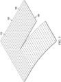
- Figure 2 is a schematic view of an example of the first layer 110, illustrating additional details that may be associated with some embodiments.
- the openings 140 may each consist essentially of one or more linear slots having a length D 1 , which may be about 3 millimeters.
- Figure 2 additionally illustrates an example of a uniform distribution pattern of the openings 140.
- the openings 140 are substantially coextensive with the first layer 110 and are distributed across the first layer 110 in a grid of parallel rows and columns, in which the slots are also mutually parallel to each other.
- the rows may be spaced by a distance D 2 , which may be about 3 millimeters on center, and the openings 140 within each of the rows may be spaced by a distance D 3 , which may be about 3 millimeters on center as illustrated in the example of Figure 2 .
- the openings 140 in adjacent rows may be aligned or offset.
- adjacent rows may be offset, as illustrated in Figure 2 , so that the openings 140 are aligned in alternating rows and separated by a distance D 4 , which may be about 6 millimeters.
- the spacing of the openings 140 may vary in some embodiments to increase the density of the openings 140 according to therapeutic requirements.
- the openings 140 of the first layer 110 may be arranged in a variety of different patterns.
- the openings 140 may be arranged in a grid with perpendicular rows.
- the openings 140 may be arranged in geometric patterns or shapes to facilitate tearing of the first layer 110 (and the other layers of the tissue interface 100) in squares, circles, spirals, or other geometric shapes.
- the slits 150 of the second layer 120 may be arranged in rows or geometric patterns corresponding to the arrangement of the openings 140 of the first layer 110.
- Figure 3 is a schematic view of an example of the third layer 130, illustrating additional details that may be associated with some embodiments.
- the first side 160 of the third layer 130 may have an adhesive coating in some examples.
- the raised features 170 may be arranged in a uniform distribution pattern, and the raised features 170 may be substantially coextensive with the third layer 130.
- the raised features 170 may be arranged across the third layer 130 in a grid of parallel rows and columns.
- the rows of raised features 170 may be spaced corresponding to the spacing of the rows of openings 140 of the first layer 110, to generally align the rows of raised features 170 and the rows of openings 140 of the first layer 110, which may facilitate tearing through the tissue interface 100.
- the raised features 170, along with the openings 140 of the first layer 110 and the slits 150 of the second layer 120, may be arranged in both parallel and perpendicular rows, in order to facilitate tearing and sizing of the tissue interface 100 in multiple directions.
- the raised features 170 may also be arranged in geometric patterns or shapes, such as squares, circles, or spirals, so that the raised features 170 may align with the openings 140 of the first layer 110 and slits 150 of the second layer 120 that are arranged in such a geometric pattern, in order to facilitate tearing and sizing the tissue interface 100 in such shapes and patterns.
- Figure 4 is a schematic view of an example of the second layer 120 and the third layer 130, according to some embodiments.
- the third layer 130 has been partially removed to expose a portion of the second layer 120, with the remaining section of the third layer 130 being adhered or laminated to the second layer 120.
- Figure 4 illustrates portions of the second layer 120 having slits 150 and the third layer 130 having raised features 170, where the second layer 120 and the third layer 130 are in a relaxed, or non-stretched state. In the pictured relaxed state, the slits 150 may be difficult to observe due to the nature of the foam material of the second layer 120. At least some of the rows of the raised features 170 of the third layer 130 may be aligned with or overlaid on rows of slits 150 of the second layer 120 to facilitate even and aligned tearing of the second layer 120 and the third layer 130.
- Figure 5 is a schematic view of the example portions of the second layer 120 and the third layer 130 of Figure 4 , showing additional details according to some illustrative embodiments.
- a portion of the third layer 130 has been removed to expose a portion of the second layer 120.
- Figure 5 illustrates the portion of the second layer 120 in a non-relaxed, or stretched state.
- the slits 150 of the second layer 120 may become significantly more visible.
- one or more rows of the slits 150 may be readily identifiable, which may assist with determining the appropriate point to tear the second layer 120 for purposes of sizing the tissue interface 100.
- Such visualization may also allow a row of raised features 170 of the third layer 130 to be aligned with the row of slits 150 along which the tissue interface 100 may be torn.
- Such alignment of the raised features 170 of the third layer 130 and the row of slits 150 of the second layer 120 may ensure that torn edges of the second layer 120 and the third layer 130, and overall the tissue interface 100, are substantially flush with each other.
- Figure 6 is a schematic view of an example portion of a tissue interface 100, showing some details that may be viewed from a top-facing or second side 115 of the tissue interface 100, according to some illustrative embodiments. More specifically, Figure 6 illustrates how an example of the tissue interface 100 may be sized by tearing through the third layer 130, second layer 120, and underlying first layer 110 along a desired tear line 610 of the tissue interface 100.
- a tear line 610 may exist where at least a portion of a row of openings 140 of the first layer 110, a portion of a row of slits 150 of the second layer 120, and a portion of a row of raised features 170 of the third layer 130 are aligned.
- the individual openings 140, slits 150, and raised features 170 along the respective rows of openings 140, slits 150, and raised features 170 do not necessarily have to align with each other between the first layer 110, the second layer 120, and the third layer 130. Additionally, not all rows of openings 140, slits 150, and raised features 170 may correspond to a tear line. As illustrated in the example of Figure 6 , portions of the first layer 110, the second layer 120, and the third layer 130 may be torn along the tear line 610, corresponding to a row of the openings 140, a row of the slits 150, and a row of the raised features 170. Through such tearing and separation of the portions of the first layer 110, second layer 120, and third layer 130, the layers of the tissue interface 100 may be sized to a corresponding tissue site.
- Figure 7 is a schematic view of the example portion of the tissue interface 100 of Figure 6 , showing further details that may be viewed from the first side 105 of the tissue interface 100, according to some illustrative embodiments. More specifically, the view of the first side 105 of the tissue interface 100 of Figure 7 illustrates how the first layer 110 may also be torn along the tear line 610 of the tissue interface 100, which may align with a row of openings 140 of the first layer 110. As collectively shown by Figures 6 and 7 , the tissue interface 100 may be torn along the tear line 610, which may correspond to and align with a row of openings 140 of the first layer 110, a row of slits 150 of the second layer 120, and a row of raised features 170 of the third layer 130.
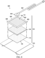
- FIG 8 is an assembly view of a dressing 800 which may incorporate an embodiment of the tissue interface 100 of Figure 1 , according to some illustrative embodiments.
- the dressing 800 may include the tissue interface 100, along with additional components that may enable or particularly facilitate use of the dressing 800 and associated tissue interface 100 with negative-pressure therapy.
- the dressing 800 may comprise the tissue interface 100, which may include the first layer 110, the second layer 120, and the third layer 130 arranged in a stacked formation.
- the dressing 800 may include a plurality of sealing strips 805, which may be positioned around the perimeter of the tissue interface 100 and sealed to an attachment surface, such as epidermis peripheral to a tissue site, to provide an effective seal around the edges of the tissue interface 100.
- the sealing strips 805 may be applied to a perimeter of the third layer 130.
- four individual sections of sealing strips 805 may be used to seal the third layer 130 to an epidermis, with each of the four sections of sealing strips 805 being applied to one of the four edges of the third layer 130.
- the sealing strips 805 may comprise polymer strips, such as polyurethane strips, having an adhesive, such as an acrylic adhesive, thereon.
- the sealing strips 805 may further or alternatively include additional layers, such as a gel layer.
- the dressing 800 may include a release liner 810 to protect the first side 105 of the tissue interface 100 prior to use.
- the release liner 810 may also provide stiffness to assist with, for example, deployment of the dressing 800.
- the release liner 810 may be, for example, a casting paper, a film, or polyethylene.
- the release liner 810 may be a polyester material such as polyethylene terephthalate (PET) or similar polar semi-crystalline polymer.
- PET polyethylene terephthalate
- the use of a polar semi-crystalline polymer for the release liner 810 may substantially preclude wrinkling or other deformation of the dressing 800.
- the polar semi-crystalline polymer may be highly orientated and resistant to softening, swelling, or other deformation that may occur when brought into contact with components of the dressing 800 or when subjected to temperature or environmental variations, or sterilization.
- a release agent may be disposed on a side of the release liner 810 that is configured to contact the first layer 110 on the first side 105 of the tissue interface 100.
- the release agent may be a silicone coating and may have a release factor suitable to facilitate removal of the release liner 810 by hand and without damaging or deforming the dressing 800.
- the release agent may be a fluorocarbon or a fluorosilicone, for example.
- the release liner 810 may be uncoated or otherwise used without a release agent.
- Figure 8 also illustrates one example of a fluid conductor 820 and a dressing interface 830.
- the fluid conductor 820 may be a flexible tube, which can be fluidly coupled on one end to the dressing interface 830.
- the dressing interface 830 may be an elbow connector, as shown in the example of Figure 8 , which can be placed over an aperture on the upper, or second side 115 of the tissue interface 100 to provide a fluid path between the fluid conductor 820 and the tissue interface 100.
- an aperture may be a centrally-positioned aperture in the third layer 130 that is cut or torn by a user.
- the fluid conductor 820 may also include a fluid delivery conduit for use with instillation therapy.
- the dressing interface 830 may include multiple fluid conduits, such as a conduit for communicating negative pressure and a fluid delivery conduit.
- the dressing interface 830 may be a V.A.C. VERAT.R.A.C. TM Pad or a SENSAT.R.A.C. TM Pad, available from KCI of San Antonio, Texas.
- tissue interface 100 Individual components of the tissue interface 100, and more generally the dressing 800, may be bonded or otherwise secured to one another with a solvent or nonsolvent adhesive, or with thermal welding, for example, without adversely affecting fluid management.
- one or more components may additionally be treated with an antimicrobial agent.
- the first layer 110, the second layer 120, and/or the third layer 130 may be coated with an antimicrobial agent.
- the fluid conductor 820, the dressing interface 830, or other portion of the dressing 800 may additionally or alternatively be treated with one or more antimicrobial agents.
- Suitable agents may include, for example, metallic silver, PHMB, iodine or its complexes and mixes such as povidone iodine, copper metal compounds, chlorhexidine, or some combination of these materials. Additionally or alternatively, one or more of the components of the tissue interface 100 may be coated with a mixture that may include citric acid and collagen, which can reduce bio-films and infections.
- the dressing 800 may be provided with different combinations of the individual layers and components.
- the tissue interface 100 may be provided as a standalone product for applying to a tissue site.
- individual layers of the dressing 800 may be omitted.
- one or more layers of the tissue interface 100 may be omitted or substituted for another layer.
- the tissue interface 100 may comprise only the first layer 110 and the second layer 120, with the film of the third layer 130 being omitted.
- the tissue interface 100, including the first layer 110 and the second layer 120 may be applied to a tissue site, with an additional sealing layer, such as a cover, being applied over the first layer 110 and second layer 120.
- the tissue interface 100 may comprise a foam layer sandwiched between two fenestrated film layers.
- such an embodiment may comprise the first layer 110 having openings 140, the second layer 120 comprising a polymeric foam and having slits 150, and an additional film layer having openings, such as a layer identical to the first layer 110.
- the foam layer and the two surrounding film layers may be stacked and laminated to each other, and then subsequently, fenestrations may be formed through all three of the layers at once using any of the cutting techniques previously mentioned, such as laser cutting, ultrasonics, or cutting using a knife or other blade.
- the tissue interface 100 may be sized to a specific region or anatomical area through cutting or tearing.
- the release liner 810 (if included) may be removed from the first side 105 of the tissue interface 100.
- the tissue interface 100 may then be torn by hand, with or without the use of any tools or instruments, along one or more tear lines that may be formed through the multiple layers of the tissue interface 100.
- the tear line may correspond to or be aligned with a row of the openings 140 of the first layer 110, a row of slits 150 of the second layer 120, and a row of raised features 170 of the third layer 130, so as to form a complete tear or cut through the layers of the tissue interface 100.
- the tear line may be made through the layers of the tissue interface 100 according to any pattern or shape, such as circles, squares, etc., formed by the openings 140, slits 150, and raised features 170.
- the tissue interface 100 may have a surface area of a circle, square, rectangle, etc.
- the tissue interface 100 may be torn or cut to an appropriate size without the individual layers, such as the first layer 110, second layer 120, and third layer 130, becoming separated from each other or falling apart.
- the tissue interface 100 may be placed within, over, on, or otherwise proximate to the tissue site, particularly a surface tissue site and adjacent epidermis.
- the first layer 110 may be interposed between the second layer 120 and the tissue site.
- the first layer 110 may be positioned over a surface wound (including edges of the wound) and undamaged epidermis to prevent direct contact between the second layer 120 and the epidermis.
- Treatment of a surface wound or placement of the tissue interface 100 on a surface wound includes placing the tissue interface 100 immediately adjacent to the surface of the body or extending over at least a portion of the surface of the body.
- the second layer 120 may be positioned between the first layer 110 and the third layer 130, with the third layer 130 capable of functioning, due to its lack of perforations, as an occlusive layer or drape over the first layer 110, the second layer 120, and the tissue site.
- the sealing strips 805 may then be placed around the perimeter of the third layer 130 of the tissue interface 100 and sealed to an attachment surface surrounding the tissue site, such as adjacent epidermis, to enable a pneumatic seal around the tissue site.
- the geometry and dimensions of the tissue interface 100 may vary to suit a particular application or anatomy.
- the geometry or dimensions of the tissue interface 100 may be adapted to provide an effective and reliable seal against challenging anatomical surfaces, such as an elbow or heel, at and around a tissue site.
- the tissue interface 100 can provide a sealed therapeutic environment proximate to a tissue site, substantially isolated from the external environment.
- a filler may also be disposed between a tissue site and the first layer 110 of the tissue interface 100.
- a wound filler may be applied interior to the periwound, and the first layer 110 may be disposed over the periwound and the wound filler.
- the filler may be a manifold, such as an open-cell foam.
- the filler may comprise or consist essentially of the same material as the second layer 120 in some embodiments.
- the dressing interface 830 may be disposed over an aperture formed in the third layer 130.
- the fluid conductor 820 may be fluidly coupled to the dressing interface 830 and to a negative-pressure source, which can reduce the pressure in the sealed therapeutic environment.
- the designs and principles of the tissue interface 100 may also be incorporated into other aspects of a dressing 800 or therapy system for treating a tissue site.
- the laminated, layered design of the tissue interface 100 may be offered in the form of low-profile fluid conduits that may be torn and sized in a customizable fashion. Such conduits may be used in addition to or in place of a fluid conductor 820 for coupling the dressing interface 830 to a negative-pressure source.
- the openings 140, slits 150, and raised features 170 of the layers of the tissue interface 100 may be particularly useful for customizing the length of such a low-profile conduit, depending on the particular application to a patient.
- tissue interface 100 may be formed in longer strips or rolls, to allow for longer low-profile fluid conduits to be formed.
- the tissue interface 100 may include specific patterns of fenestrations or other openings through the respective layers of the tissue interface 100 to facilitate custom-sizing to form a fluid conduit.
- the tissue interface 100 may include a portion having a plurality of parallel and perpendicular rows of fenestrations, as well as an additional portion having fenestrations in a pattern of concentric circles. The portion of the tissue interface 100 having the concentric circles may be formed into an interface or landing pad where either an additional fluid conduit or possibly tissue dressing may be fluidly connected to the customized low-profile fluid conduit.
- FIG. 9 is a simplified functional block diagram of an example embodiment of a therapy system 900 that can provide negative-pressure therapy to a tissue site in accordance with this specification.
- the therapy system 900 may include a source or supply of negative pressure, such as a negative-pressure source 905, and one or more distribution components.
- a distribution component is preferably detachable and may be disposable, reusable, or recyclable.
- a dressing, such as the dressing 800, and a fluid container, such as a container 915 are examples of distribution components that may be associated with some examples of the therapy system 900.
- the container 915 is representative of a container, canister, pouch, or other storage component, which can be used to manage exudates and other fluids withdrawn from a tissue site.
- the dressing 800 may comprise or consist essentially of the tissue interface 100.
- the dressing 800 may further include a cover 925.
- the cover 925 may provide an additional bacterial barrier and protection from physical trauma.
- the cover 925 may also be constructed from a material that can reduce evaporative losses and provide a fluid seal between two components or two environments, such as between a therapeutic environment and a local external environment.
- the cover 925 may comprise or consist of, for example, an elastomeric film or membrane that can provide a seal adequate to maintain a negative pressure at a tissue site for a given negative-pressure source.
- the cover 925 may have a high moisture-vapor transmission rate (MVTR) in some applications.
- the MVTR may be at least 250 grams per square meter per twenty-four hours in some embodiments, measured using an upright cup technique according to ASTM E96/E96M Upright Cup Method at 38°C and 10% relative humidity (RH). In some embodiments, an MVTR up to 5,000 grams per square meter per twenty-four hours may provide effective breathability and mechanical properties.
- an attachment device may be used to attach the cover 925 to an attachment surface, such as undamaged epidermis, a gasket, or another cover.
- an attachment device may be a medically-acceptable, pressure-sensitive adhesive, such as an acrylic adhesive, configured to bond the cover 925 to epidermis around a tissue site.
- Other examples of an attachment device may include a double-sided tape, paste, hydrocolloid, hydrogel, silicone gel, or organogel.
- the cover 925 may be a polymer drape, such as a polyurethane film, that is permeable to water vapor but impermeable to liquid.
- a polymer drape such as a polyurethane film
- Such drapes typically have a thickness in the range of 25-50 microns.
- the permeability generally should be low enough that a desired negative pressure may be maintained.
- the cover 925 may comprise, for example, one or more of the following materials: polyurethane (PU), such as hydrophilic polyurethane; cellulosics; hydrophilic polyamides; polyvinyl alcohol; polyvinyl pyrrolidone; hydrophilic acrylics; silicones, such as hydrophilic silicone elastomers; natural rubbers; polyisoprene; styrene butadiene rubber; chloroprene rubber; polybutadiene; nitrile rubber; butyl rubber; ethylene propylene rubber; ethylene propylene diene monomer; chlorosulfonated polyethylene; polysulfide rubber; ethylene vinyl acetate (EVA); co-polyester; and polyether block polymide copolymers.
- PU polyurethane
- PU polyurethane
- hydrophilic polyurethane such as hydrophilic polyurethane
- cellulosics such as cellulosics; hydrophilic polyamides
- the cover 925 may comprise INSPIRE 2301 having an MVTR (upright cup technique) of 2600 g/m 2 /24 hours and a thickness of about 30 microns.
- the therapy system 900 may also include a regulator or controller, such as a controller 930. Additionally, the therapy system 900 may include sensors to measure operating parameters and provide feedback signals to the controller 930 indicative of the operating parameters. As illustrated in Figure 9 , for example, the therapy system 900 may include a first sensor 935 and a second sensor 940 coupled to the controller 930.
- Some components of the therapy system 900 may be housed within or used in conjunction with other components, such as sensors, processing units, alarm indicators, memory, databases, software, display devices, or user interfaces that further facilitate therapy.
- the negative-pressure source 905 may be combined with the controller 930 and other components into a therapy unit.
- components of the therapy system 900 may be coupled directly or indirectly.
- Coupling may include fluid, mechanical, thermal, electrical, or chemical coupling (such as a chemical bond), or some combination of coupling in some contexts.
- a negative-pressure supply such as the negative-pressure source 905
- Negative pressure generally refers to a pressure less than a local ambient pressure, such as the ambient pressure in a local environment external to a sealed therapeutic environment. In many cases, the local ambient pressure may also be the atmospheric pressure at which a tissue site is located. Alternatively, the pressure may be less than a hydrostatic pressure associated with tissue at the tissue site. Unless otherwise indicated, values of pressure stated herein are gauge pressures.
- references to increases in negative pressure typically refer to a decrease in absolute pressure, while decreases in negative pressure typically refer to an increase in absolute pressure. While the amount and nature of negative pressure provided by the negative-pressure source 905 may vary according to therapeutic requirements, the pressure is generally a low vacuum, also commonly referred to as a rough vacuum, between -5 mm Hg (-667 Pa) and -500 mm Hg (-66.7 kPa). Common therapeutic ranges are between -50 mm Hg (-6.7 kPa) and -300 mm Hg (-39.9 kPa).
- a controller such as the controller 930, may be a microprocessor or computer programmed to operate one or more components of the therapy system 900, such as the negative-pressure source 905.
- the controller 930 may control one or more operating parameters of the therapy system 900, which may include the power applied to the negative-pressure source 905, the pressure generated by the negative-pressure source 905, or the pressure distributed to the tissue interface 100, for example.
- the controller 930 is also preferably configured to receive one or more input signals, such as a feedback signal, and programmed to modify one or more operating parameters based on the input signals.
- Sensors such as the first sensor 935 and the second sensor 940, are generally known in the art as any apparatus operable to detect or measure a physical phenomenon or property, and generally provide a signal indicative of the phenomenon or property that is detected or measured.
- the first sensor 935 and the second sensor 940 may be configured to measure one or more operating parameters of the therapy system 900.
- the first sensor 935 may be a transducer configured to measure pressure in a pneumatic pathway and convert the measurement to a signal indicative of the pressure measured.
- the second sensor 940 may optionally measure operating parameters of the negative-pressure source 905, such as a voltage or current, in some embodiments.
- the tissue interface 100 may be placed within, over, on, or otherwise proximate to a tissue site.
- the cover 925 may optionally be placed over the tissue interface 100 and sealed to an attachment surface near a tissue site.
- the cover 925 may be sealed to undamaged epidermis peripheral to a tissue site.
- the dressing 800 can provide a sealed therapeutic environment proximate to a tissue site, substantially isolated from the external environment, and the negative-pressure source 905 can reduce pressure in the sealed therapeutic environment.
- the fluid mechanics of using a negative-pressure source to reduce pressure in another component or location, such as within a sealed therapeutic environment, can be mathematically complex.
- the basic principles of fluid mechanics applicable to negative-pressure therapy are generally well-known to those skilled in the art, and the process of reducing pressure may be described illustratively herein as "delivering,” “distributing,” or “generating” negative pressure, for example.
- downstream typically implies something in a fluid path relatively closer to a source of negative pressure or further away from a source of positive pressure.
- upstream implies something relatively further away from a source of negative pressure or closer to a source of positive pressure.
- fluid inlet or “outlet” in such a frame of reference. This orientation is generally presumed for purposes of describing various features and components herein.
- the fluid path may also be reversed in some applications, such as by substituting a positive-pressure source for a negative-pressure source, and this descriptive convention should not be construed as a limiting convention.
- Negative pressure applied across the tissue site through the tissue interface 100 in the sealed therapeutic environment can induce macro-strain and micro-strain in the tissue site. Negative pressure can also remove exudate and other fluid from a tissue site, which can be collected in container 915.
- negative pressure applied through the tissue interface 100 can create a negative pressure differential across the openings 140 in the first layer 110, which can open or expand the openings 140 from their resting state.
- a pressure gradient across the fenestrations can strain the adjacent material of the first layer 110 and increase the dimensions of the fenestrations to allow liquid movement through them, similar to the operation of a duckbill valve.
- Opening the openings 140 can allow exudate and other liquid movement through the openings 140, through the second layer 120, the third layer 130, and into the container 915.
- Changes in pressure can also cause the second layer 120 to expand and contract, and the first layer 110 may protect the epidermis from irritation caused by the movement of the second layer 120.
- the first layer 110 can also substantially reduce or prevent exposure of tissue to the second layer 120, which can inhibit growth of tissue into the second layer 120.
- the controller 930 may receive and process data from one or more sensors, such as the first sensor 935. The controller 930 may also control the operation of one or more components of the therapy system 900 to manage the pressure delivered to the tissue interface 100.
- controller 930 may include an input for receiving a desired target pressure and may be programmed for processing data relating to the setting and inputting of the target pressure to be applied to the tissue interface 100.
- the target pressure may be a fixed pressure value set by an operator as the target negative pressure desired for therapy at a tissue site and then provided as input to the controller 930.
- the target pressure may vary from tissue site to tissue site based on the type of tissue forming a tissue site, the type of injury or wound (if any), the medical condition of the patient, and the preference of the attending physician.
- the controller 930 can operate the negative-pressure source 905 in one or more control modes based on the target pressure and may receive feedback from one or more sensors to maintain the target pressure at the tissue interface 100.
- the pressure differential across the openings 140 of the first layer 110 of the tissue interface 100 can dissipate, allowing the openings 140 to move to their resting state and prevent or reduce the rate at which exudate or other liquid can return to the tissue site through the first layer 110.
- tissue interfaces for applying to tissue sites can require time and skill to be properly sized and applied to achieve a good fit and seal, in addition to requiring one or more cutting or sizing tools.
- some embodiments of the tissue interface 100 may be applied to a tissue site with simple sizing and cutting steps, therefore reducing the amount of time and effort as compared to some previous dressings.
- the tissue interface 100 may be torn by hand, without requiring the use of scissors or scalpels.
- multiple layers of the tissue interface 100 may be torn at once, thus obviating challenges associated with separately sizing the individual layers and potential sizing inconsistencies between the layers.
- the tissue interface 100 may offer a fully-integrated dressing that can be easily cut and applied to a tissue site (including over the periwound), while providing many benefits of other dressings that may require more complex sizing protocols. Such benefits may include good manifolding, beneficial granulation, and protection of the peripheral tissue from maceration.
- the tissue interface 100 may also conform to and occupy a significant space at a tissue site, which may be particularly advantageous for wounds having moderate depth and medium-to-high levels of exudate. Additionally, the tissue interface 100 can promote granulation while reducing the opportunity for tissue in-growth by containing the porous foam material within other film layers. As a result, the tissue interface 100 can be worn for extended wear times, for example up to seven days.
- the designs of some embodiments of the tissue interface 100 may also allow for a more custom- or specifically-tailored size of the tissue interface 100 to be accomplished, as compared to some other dressing materials commercially available, such as dressing materials which may include only large, pre-cut sections.
- the plurality of the openings 140 of the first layer 110, the slits 150 of the second layer 120, and the raised features 170 of the third layer 130 may allow for one or more tear lines to be made through the tissue interface 100 at specific locations, thus allowing the size of the tissue interface 100 to closely correspond to the area or size of the tissue site to which it is to be applied.
- the flexibility offered by being able to tear the tissue interface 100 along multiple specific lines may also result in fewer wasted dressing materials. For example, a user may make multiple or repeated tears through the tissue interface 100 in order to make adjustments to the size of the tissue interface 100 to accomplish an appropriate fit for the tissue site being treated.
Landscapes
- Health & Medical Sciences (AREA)
- Public Health (AREA)
- Engineering & Computer Science (AREA)
- Veterinary Medicine (AREA)
- Life Sciences & Earth Sciences (AREA)
- Animal Behavior & Ethology (AREA)
- General Health & Medical Sciences (AREA)
- Heart & Thoracic Surgery (AREA)
- Vascular Medicine (AREA)
- Biomedical Technology (AREA)
- Chemical & Material Sciences (AREA)
- Hematology (AREA)
- Materials Engineering (AREA)
- Epidemiology (AREA)
- Anesthesiology (AREA)
- Chemical Kinetics & Catalysis (AREA)
- Dispersion Chemistry (AREA)
- Materials For Medical Uses (AREA)
- Media Introduction/Drainage Providing Device (AREA)
Claims (22)
- Matériau de pansement, comprenant :une première couche (110) comprenant un premier film de matériau non poreux ayant une pluralité d'ouvertures (140) ;une deuxième couche (120) adjacente à la première couche (110), la deuxième couche (120) comprenant un collecteur ayant une pluralité de fentes (150), dans lequel le collecteur comprend une mousse ; etune troisième couche (130) adjacente à la deuxième couche (120) et comprenant un second film de matériau non poreux ayant des caractéristiques en relief (170) ;dans lequel au moins une partie de la pluralité d'ouvertures (140), une partie de la pluralité de fentes (150) et une partie des caractéristiques en relief (170) sont alignées pour définir une ligne de déchirure.
- Matériau de pansement selon la revendication 1, dans lequel le premier film comprend un matériau en polyuréthane.
- Matériau de pansement selon la revendication 1, dans lequel le collecteur comprend une mousse de polyuréthane.
- Matériau de pansement selon la revendication 1, dans lequel :le premier film comprend un matériau en polyuréthane ; etle second film comprend un matériau en polyuréthane.
- Matériau de pansement selon la revendication 1, dans lequel :la pluralité d'ouvertures (140) et la pluralité de fentes (150) sont formées par la formation d'une pluralité de fenestrations s'étendant à travers la première couche (110) et la deuxième couche (120) pour créer des paires d'ouvertures (140) et de fentes (150) alignées ; etdans lequel chacune parmi la pluralité de fenestrations a une longueur comprise entre 1 mm et 5 mm.
- Matériau de pansement selon la revendication 5, dans lequel chacune parmi la pluralité de fenestrations a une largeur inférieure ou égale à 2 mm.
- Matériau de pansement selon la revendication 5, dans lequel la pluralité de fenestrations est coextensive avec la première couche (110).
- Matériau de pansement selon la revendication 1, dans lequel le premier film est un film enduit d'adhésif.
- Matériau de pansement selon la revendication 1, dans lequel :la pluralité d'ouvertures (140) est répartie sur la première couche (110) en rangées et colonnes parallèles ; etles rangées sont espacées d'environ 3 mm au centre.
- Matériau de pansement selon la revendication 1, dans lequel :la pluralité d'ouvertures (140) est répartie sur la première couche (110) en rangées et colonnes parallèles ;les rangées sont espacées de 3 mm de centre à centre ; etles ouvertures (140) dans chacune des rangées sont espacées d'environ 3 mm au centre.
- Matériau de pansement selon la revendication 10, dans lequel la pluralité d'ouvertures (140) dans les rangées adjacentes est décalée.
- Matériau de pansement selon la revendication 1, dans lequel :le second film est un film enduit d'adhésif ; etle second film est laminé sur la deuxième couche (120).
- Matériau de pansement selon la revendication 1, dans lequel le second film est un film hautement respirant.
- Matériau de pansement selon la revendication 1, dans lequel au moins une partie de la pluralité d'ouvertures (140), une partie de la pluralité de fentes (150) et une partie des caractéristiques en relief (170) sont alignées selon un motif circulaire.
- Matériau de pansement selon la revendication 1, dans lequel au moins une partie de la pluralité d'ouvertures (140), une partie de la pluralité de fentes (150) et une partie des caractéristiques en relief (170) sont alignées selon un motif linéaire.
- Matériau de pansement selon la revendication 1, dans lequel au moins une partie de la pluralité d'ouvertures (140), une partie de la pluralité de fentes (150) et une partie des caractéristiques en relief (170) sont alignées dans un motif ayant des formes géométriques.
- Matériau de pansement selon la revendication 16, dans lequel les formes géométriques comprennent des carrés.
- Matériau de pansement selon la revendication 16, dans lequel les formes géométriques comportent des cercles.
- Matériau de pansement selon la revendication 1, dans lequel la pluralité d'ouvertures (140) est répartie sur la première couche (110) en rangées perpendiculaires.
- Procédé de fabrication d'un matériau de pansement selon l'une quelconque revendication précédente, comprenant :la stratification d'un premier film sur une première face d'une couche de mousse ;la création d'une pluralité de fenestrations à travers le premier film et la couche de mousse pour fournir une pluralité d'ouvertures (140) dans le premier film et une pluralité de fentes (150) dans la couche de mousse ; etla stratification d'un second film comprenant une pluralité de caractéristiques en relief (170) sur une seconde face de la couche de mousse.
- Système de traitement d'un site tissulaire, comprenant :un pansement pour cavité de plaie, comprenant le matériau de pansement selon l'une quelconque des revendications 1 à 19 ;une pluralité de bandes d'étanchéité (805) adaptées pour être positionnées sur un périmètre de la troisième couche (130) opposée à la deuxième couche (120) du matériau de pansement ; etune interface (830) adaptée pour être accouplée au pansement pour cavité de plaie.
- Système selon la revendication 21, comprenant en outre une source de pression négative (905) adaptée pour être reliée fluidiquement au pansement pour cavité de plaie à travers l'interface (830).
Applications Claiming Priority (2)
| Application Number | Priority Date | Filing Date | Title |
|---|---|---|---|
| US201962797632P | 2019-01-28 | 2019-01-28 | |
| PCT/US2020/012560 WO2020159675A1 (fr) | 2019-01-28 | 2020-01-07 | Structure de pansement déchirable |
Publications (2)
| Publication Number | Publication Date |
|---|---|
| EP3917471A1 EP3917471A1 (fr) | 2021-12-08 |
| EP3917471B1 true EP3917471B1 (fr) | 2024-06-19 |
Family
ID=69423427
Family Applications (1)
| Application Number | Title | Priority Date | Filing Date |
|---|---|---|---|
| EP20703343.2A Active EP3917471B1 (fr) | 2019-01-28 | 2020-01-07 | Structure de pansement déchirable |
Country Status (5)
| Country | Link |
|---|---|
| US (1) | US12329614B2 (fr) |
| EP (1) | EP3917471B1 (fr) |
| JP (1) | JP7367034B2 (fr) |
| CN (1) | CN113301873A (fr) |
| WO (1) | WO2020159675A1 (fr) |
Cited By (1)
| Publication number | Priority date | Publication date | Assignee | Title |
|---|---|---|---|---|
| US12485043B2 (en) | 2021-07-23 | 2025-12-02 | Convatec Limited | Selectively configurable wound dressing |
Families Citing this family (15)
| Publication number | Priority date | Publication date | Assignee | Title |
|---|---|---|---|---|
| GB0808376D0 (en) | 2008-05-08 | 2008-06-18 | Bristol Myers Squibb Co | Wound dressing |
| GB201020236D0 (en) | 2010-11-30 | 2011-01-12 | Convatec Technologies Inc | A composition for detecting biofilms on viable tissues |
| PL2648795T3 (pl) | 2010-12-08 | 2023-05-08 | Convatec Technologies Inc. | System do usuwania wysięków z miejsca rany |
| CN103347562B (zh) | 2010-12-08 | 2016-08-10 | 康沃特克科技公司 | 伤口分泌液系统附件 |
| GB2497406A (en) | 2011-11-29 | 2013-06-12 | Webtec Converting Llc | Dressing with a perforated binder layer |
| JP2016507663A (ja) | 2012-12-20 | 2016-03-10 | コンバテック・テクノロジーズ・インコーポレイテッドConvatec Technologies Inc | 化学修飾セルロース系繊維の加工 |
| GB201608099D0 (en) | 2016-05-09 | 2016-06-22 | Convatec Technologies Inc | Negative pressure wound dressing |
| US12161792B2 (en) | 2017-11-16 | 2024-12-10 | Convatec Limited | Fluid collection apparatus |
| EP4295869B1 (fr) | 2019-06-03 | 2026-01-28 | Convatec Limited | Dispositifs pour perturber et contenir des agents pathogènes |
| US11771819B2 (en) | 2019-12-27 | 2023-10-03 | Convatec Limited | Low profile filter devices suitable for use in negative pressure wound therapy systems |
| US11331221B2 (en) | 2019-12-27 | 2022-05-17 | Convatec Limited | Negative pressure wound dressing |
| EP4262655B1 (fr) * | 2020-12-21 | 2025-12-10 | Solventum Intellectual Properties Company | Bandes adhésives double face avec adhésion on-demand |
| CN118450873A (zh) * | 2021-12-17 | 2024-08-06 | 凯希制造无限公司 | 具有带狭缝的泡沫层的负压伤口治疗敷料 |
| TWI846285B (zh) * | 2023-01-18 | 2024-06-21 | 達運精密工業股份有限公司 | 傷口敷料及其製造方法 |
| WO2025008418A1 (fr) * | 2023-07-05 | 2025-01-09 | T.J.Smith And Nephew,Limited | Dispositifs et procédés de thérapie de plaie par pression négative |
Family Cites Families (152)
| Publication number | Priority date | Publication date | Assignee | Title |
|---|---|---|---|---|
| US1355846A (en) | 1920-02-06 | 1920-10-19 | David A Rannells | Medical appliance |
| US2547758A (en) | 1949-01-05 | 1951-04-03 | Wilmer B Keeling | Instrument for treating the male urethra |
| US2632443A (en) | 1949-04-18 | 1953-03-24 | Eleanor P Lesher | Surgical dressing |
| GB692578A (en) | 1949-09-13 | 1953-06-10 | Minnesota Mining & Mfg | Improvements in or relating to drape sheets for surgical use |
| US2682873A (en) | 1952-07-30 | 1954-07-06 | Johnson & Johnson | General purpose protective dressing |
| NL189176B (nl) | 1956-07-13 | 1900-01-01 | Hisamitsu Pharmaceutical Co | Pleister op basis van een synthetische rubber. |
| US2969057A (en) | 1957-11-04 | 1961-01-24 | Brady Co W H | Nematodic swab |
| US3066672A (en) | 1960-09-27 | 1962-12-04 | Jr William H Crosby | Method and apparatus for serial sampling of intestinal juice |
| US3367332A (en) | 1965-08-27 | 1968-02-06 | Gen Electric | Product and process for establishing a sterile area of skin |
| US3520300A (en) | 1967-03-15 | 1970-07-14 | Amp Inc | Surgical sponge and suction device |
| US3568675A (en) | 1968-08-30 | 1971-03-09 | Clyde B Harvey | Fistula and penetrating wound dressing |
| US3682180A (en) | 1970-06-08 | 1972-08-08 | Coilform Co Inc | Drain clip for surgical drain |
| BE789293Q (fr) | 1970-12-07 | 1973-01-15 | Parke Davis & Co | Pansement medico-chirugical pour brulures et lesions analogues |
| US3826254A (en) | 1973-02-26 | 1974-07-30 | Verco Ind | Needle or catheter retaining appliance |
| DE2527706A1 (de) | 1975-06-21 | 1976-12-30 | Hanfried Dr Med Weigand | Einrichtung zum einleiten von kontrastmittel in einen kuenstlichen darmausgang |
| DE2640413C3 (de) | 1976-09-08 | 1980-03-27 | Richard Wolf Gmbh, 7134 Knittlingen | Katheter-Überwachungsgerät |
| NL7710909A (nl) | 1976-10-08 | 1978-04-11 | Smith & Nephew | Samengestelde hechtstrook. |
| GB1562244A (en) | 1976-11-11 | 1980-03-05 | Lock P M | Wound dressing materials |
| US4080970A (en) | 1976-11-17 | 1978-03-28 | Miller Thomas J | Post-operative combination dressing and internal drain tube with external shield and tube connector |
| US4139004A (en) | 1977-02-17 | 1979-02-13 | Gonzalez Jr Harry | Bandage apparatus for treating burns |
| US4184510A (en) | 1977-03-15 | 1980-01-22 | Fibra-Sonics, Inc. | Valued device for controlling vacuum in surgery |
| US4165748A (en) | 1977-11-07 | 1979-08-28 | Johnson Melissa C | Catheter tube holder |
| US4245637A (en) | 1978-07-10 | 1981-01-20 | Nichols Robert L | Shutoff valve sleeve |
| SE414994B (sv) | 1978-11-28 | 1980-09-01 | Landstingens Inkopscentral | Venkateterforband |
| WO1980001139A1 (fr) | 1978-12-06 | 1980-06-12 | Svedman Paul | Dispositif de traitement des tissus, par exemple de la peau |
| US4266545A (en) | 1979-04-06 | 1981-05-12 | Moss James P | Portable suction device for collecting fluids from a closed wound |
| US4284079A (en) | 1979-06-28 | 1981-08-18 | Adair Edwin Lloyd | Method for applying a male incontinence device |
| US4261363A (en) | 1979-11-09 | 1981-04-14 | C. R. Bard, Inc. | Retention clips for body fluid drains |
| US4569348A (en) | 1980-02-22 | 1986-02-11 | Velcro Usa Inc. | Catheter tube holder strap |
| WO1981002516A1 (fr) | 1980-03-11 | 1981-09-17 | E Schmid | Coussin pour comprimer un element de peau greffe |
| US4297995A (en) | 1980-06-03 | 1981-11-03 | Key Pharmaceuticals, Inc. | Bandage containing attachment post |
| US4333468A (en) | 1980-08-18 | 1982-06-08 | Geist Robert W | Mesentery tube holder apparatus |
| US4465485A (en) | 1981-03-06 | 1984-08-14 | Becton, Dickinson And Company | Suction canister with unitary shut-off valve and filter features |
| US4392853A (en) | 1981-03-16 | 1983-07-12 | Rudolph Muto | Sterile assembly for protecting and fastening an indwelling device |
| US4373519A (en) | 1981-06-26 | 1983-02-15 | Minnesota Mining And Manufacturing Company | Composite wound dressing |
| US4392858A (en) | 1981-07-16 | 1983-07-12 | Sherwood Medical Company | Wound drainage device |
| US4419097A (en) | 1981-07-31 | 1983-12-06 | Rexar Industries, Inc. | Attachment for catheter tube |
| US4465729A (en) * | 1981-08-05 | 1984-08-14 | Clopay Corporation | Cross-tearable plastic films |
| AU550575B2 (en) | 1981-08-07 | 1986-03-27 | Richard Christian Wright | Wound drainage device |
| SE429197B (sv) | 1981-10-14 | 1983-08-22 | Frese Nielsen | Anordning for behandling av sar |
| DE3146266A1 (de) | 1981-11-21 | 1983-06-01 | B. Braun Melsungen Ag, 3508 Melsungen | Kombinierte vorrichtung fuer eine medizinische saugdrainage |
| US4551139A (en) | 1982-02-08 | 1985-11-05 | Marion Laboratories, Inc. | Method and apparatus for burn wound treatment |
| US4475909A (en) | 1982-05-06 | 1984-10-09 | Eisenberg Melvin I | Male urinary device and method for applying the device |
| DE3361779D1 (en) | 1982-07-06 | 1986-02-20 | Dow Corning | Medical-surgical dressing and a process for the production thereof |
| NZ206837A (en) | 1983-01-27 | 1986-08-08 | Johnson & Johnson Prod Inc | Thin film adhesive dressing:backing material in three sections |
| US4548202A (en) | 1983-06-20 | 1985-10-22 | Ethicon, Inc. | Mesh tissue fasteners |
| US4540412A (en) | 1983-07-14 | 1985-09-10 | The Kendall Company | Device for moist heat therapy |
| US4543100A (en) | 1983-11-01 | 1985-09-24 | Brodsky Stuart A | Catheter and drain tube retainer |
| US4525374A (en) | 1984-02-27 | 1985-06-25 | Manresa, Inc. | Treating hydrophobic filters to render them hydrophilic |
| CA1286177C (fr) | 1984-05-03 | 1991-07-16 | Smith And Nephew Associated Companies Plc | Pansement adhesif |
| US4897081A (en) | 1984-05-25 | 1990-01-30 | Thermedics Inc. | Percutaneous access device |
| US5215522A (en) | 1984-07-23 | 1993-06-01 | Ballard Medical Products | Single use medical aspirating device and method |
| GB8419745D0 (en) | 1984-08-02 | 1984-09-05 | Smith & Nephew Ass | Wound dressing |
| US4872450A (en) | 1984-08-17 | 1989-10-10 | Austad Eric D | Wound dressing and method of forming same |
| US4826494A (en) | 1984-11-09 | 1989-05-02 | Stryker Corporation | Vacuum wound drainage system |
| US4655754A (en) | 1984-11-09 | 1987-04-07 | Stryker Corporation | Vacuum wound drainage system and lipids baffle therefor |
| US4605399A (en) | 1984-12-04 | 1986-08-12 | Complex, Inc. | Transdermal infusion device |
| US5037397A (en) | 1985-05-03 | 1991-08-06 | Medical Distributors, Inc. | Universal clamp |
| US4640688A (en) | 1985-08-23 | 1987-02-03 | Mentor Corporation | Urine collection catheter |
| US4710165A (en) | 1985-09-16 | 1987-12-01 | Mcneil Charles B | Wearable, variable rate suction/collection device |
| US4758220A (en) | 1985-09-26 | 1988-07-19 | Alcon Laboratories, Inc. | Surgical cassette proximity sensing and latching apparatus |
| US4733659A (en) | 1986-01-17 | 1988-03-29 | Seton Company | Foam bandage |
| WO1987004626A1 (fr) | 1986-01-31 | 1987-08-13 | Osmond, Roger, L., W. | Systeme de succion pour drainage de blessures et drainage gastro-intestinal |
| US4838883A (en) | 1986-03-07 | 1989-06-13 | Nissho Corporation | Urine-collecting device |
| JPS62281965A (ja) | 1986-05-29 | 1987-12-07 | テルモ株式会社 | カテ−テルおよびカテ−テル用固定部材 |
| GB8621884D0 (en) | 1986-09-11 | 1986-10-15 | Bard Ltd | Catheter applicator |
| GB2195255B (en) | 1986-09-30 | 1991-05-01 | Vacutec Uk Limited | Apparatus for vacuum treatment of an epidermal surface |
| JPS6359625U (fr) * | 1986-10-02 | 1988-04-20 | ||
| US4743232A (en) | 1986-10-06 | 1988-05-10 | The Clinipad Corporation | Package assembly for plastic film bandage |
| DE3634569A1 (de) | 1986-10-10 | 1988-04-21 | Sachse Hans E | Kondomkatheter, ein harnroehrenkatheter zur verhinderung von aufsteigenden infektionen |
| JPS63135179A (ja) | 1986-11-26 | 1988-06-07 | 立花 俊郎 | 薬物の経皮投与具 |
| GB8628564D0 (en) | 1986-11-28 | 1987-01-07 | Smiths Industries Plc | Anti-foaming agent suction apparatus |
| GB8706116D0 (en) | 1987-03-14 | 1987-04-15 | Smith & Nephew Ass | Adhesive dressings |
| US4787888A (en) | 1987-06-01 | 1988-11-29 | University Of Connecticut | Disposable piezoelectric polymer bandage for percutaneous delivery of drugs and method for such percutaneous delivery (a) |
| US4863449A (en) | 1987-07-06 | 1989-09-05 | Hollister Incorporated | Adhesive-lined elastic condom cathether |
| US5176663A (en) | 1987-12-02 | 1993-01-05 | Pal Svedman | Dressing having pad with compressibility limiting elements |
| US4906240A (en) | 1988-02-01 | 1990-03-06 | Matrix Medica, Inc. | Adhesive-faced porous absorbent sheet and method of making same |
| US4985019A (en) | 1988-03-11 | 1991-01-15 | Michelson Gary K | X-ray marker |
| GB8812803D0 (en) | 1988-05-28 | 1988-06-29 | Smiths Industries Plc | Medico-surgical containers |
| US4919654A (en) | 1988-08-03 | 1990-04-24 | Kalt Medical Corporation | IV clamp with membrane |
| US5000741A (en) | 1988-08-22 | 1991-03-19 | Kalt Medical Corporation | Transparent tracheostomy tube dressing |
| US5059596A (en) | 1989-01-16 | 1991-10-22 | Roussel Uclaf | Azabicyclo compounds |
| GB8906100D0 (en) | 1989-03-16 | 1989-04-26 | Smith & Nephew | Laminates |
| US5261893A (en) | 1989-04-03 | 1993-11-16 | Zamierowski David S | Fastening system and method |
| US5527293A (en) | 1989-04-03 | 1996-06-18 | Kinetic Concepts, Inc. | Fastening system and method |
| US5100396A (en) | 1989-04-03 | 1992-03-31 | Zamierowski David S | Fluidic connection system and method |
| US4969880A (en) | 1989-04-03 | 1990-11-13 | Zamierowski David S | Wound dressing and treatment method |
| US5086764A (en) * | 1989-04-13 | 1992-02-11 | Thomas Gilman | Absorbent dressing |
| JP2719671B2 (ja) | 1989-07-11 | 1998-02-25 | 日本ゼオン株式会社 | 創傷被覆材 |
| US5358494A (en) | 1989-07-11 | 1994-10-25 | Svedman Paul | Irrigation dressing |
| US5232453A (en) | 1989-07-14 | 1993-08-03 | E. R. Squibb & Sons, Inc. | Catheter holder |
| GB2235877A (en) | 1989-09-18 | 1991-03-20 | Antonio Talluri | Closed wound suction apparatus |
| US5134994A (en) | 1990-02-12 | 1992-08-04 | Say Sam L | Field aspirator in a soft pack with externally mounted container |
| US5092858A (en) | 1990-03-20 | 1992-03-03 | Becton, Dickinson And Company | Liquid gelling agent distributor device |
| US5149331A (en) | 1991-05-03 | 1992-09-22 | Ariel Ferdman | Method and device for wound closure |
| US5278100A (en) | 1991-11-08 | 1994-01-11 | Micron Technology, Inc. | Chemical vapor deposition technique for depositing titanium silicide on semiconductor wafers |
| US5636643A (en) | 1991-11-14 | 1997-06-10 | Wake Forest University | Wound treatment employing reduced pressure |
| US5645081A (en) | 1991-11-14 | 1997-07-08 | Wake Forest University | Method of treating tissue damage and apparatus for same |
| US5279550A (en) | 1991-12-19 | 1994-01-18 | Gish Biomedical, Inc. | Orthopedic autotransfusion system |
| US5167613A (en) | 1992-03-23 | 1992-12-01 | The Kendall Company | Composite vented wound dressing |
| FR2690617B1 (fr) | 1992-04-29 | 1994-06-24 | Cbh Textile | Pansement adhesif transparent. |
| DE4306478A1 (de) | 1993-03-02 | 1994-09-08 | Wolfgang Dr Wagner | Drainagevorrichtung, insbesondere Pleuradrainagevorrichtung, und Drainageverfahren |
| US6241747B1 (en) | 1993-05-03 | 2001-06-05 | Quill Medical, Inc. | Barbed Bodily tissue connector |
| US5342376A (en) | 1993-05-03 | 1994-08-30 | Dermagraphics, Inc. | Inserting device for a barbed tissue connector |
| US5344415A (en) | 1993-06-15 | 1994-09-06 | Deroyal Industries, Inc. | Sterile system for dressing vascular access site |
| ES2133563T3 (es) * | 1993-07-21 | 1999-09-16 | Smith & Nephew | Vendaje quirurgico. |
| US5437651A (en) | 1993-09-01 | 1995-08-01 | Research Medical, Inc. | Medical suction apparatus |
| US5549584A (en) | 1994-02-14 | 1996-08-27 | The Kendall Company | Apparatus for removing fluid from a wound |
| US5556375A (en) | 1994-06-16 | 1996-09-17 | Hercules Incorporated | Wound dressing having a fenestrated base layer |
| US5607388A (en) | 1994-06-16 | 1997-03-04 | Hercules Incorporated | Multi-purpose wound dressing |
| US5664270A (en) | 1994-07-19 | 1997-09-09 | Kinetic Concepts, Inc. | Patient interface system |
| ATE172377T1 (de) | 1994-08-22 | 1998-11-15 | Kinetic Concepts Inc | Wunddrainagevorrichtung |
| DE29504378U1 (de) | 1995-03-15 | 1995-09-14 | MTG Medizinisch, technische Gerätebau GmbH, 66299 Friedrichsthal | Elektronisch geregelte Niedervakuumpumpe für die Thorax- und Wunddrainage |
| GB9523253D0 (en) | 1995-11-14 | 1996-01-17 | Mediscus Prod Ltd | Portable wound treatment apparatus |
| US6135116A (en) | 1997-07-28 | 2000-10-24 | Kci Licensing, Inc. | Therapeutic method for treating ulcers |
| AU755496B2 (en) | 1997-09-12 | 2002-12-12 | Kci Licensing, Inc. | Surgical drape and suction head for wound treatment |
| GB9719520D0 (en) | 1997-09-12 | 1997-11-19 | Kci Medical Ltd | Surgical drape and suction heads for wound treatment |
| US6071267A (en) | 1998-02-06 | 2000-06-06 | Kinetic Concepts, Inc. | Medical patient fluid management interface system and method |
| US6488643B1 (en) | 1998-10-08 | 2002-12-03 | Kci Licensing, Inc. | Wound healing foot wrap |
| US6287316B1 (en) | 1999-03-26 | 2001-09-11 | Ethicon, Inc. | Knitted surgical mesh |
| US6856821B2 (en) | 2000-05-26 | 2005-02-15 | Kci Licensing, Inc. | System for combined transcutaneous blood gas monitoring and vacuum assisted wound closure |
| US7799004B2 (en) | 2001-03-05 | 2010-09-21 | Kci Licensing, Inc. | Negative pressure wound treatment apparatus and infection identification system and method |
| US6991643B2 (en) | 2000-12-20 | 2006-01-31 | Usgi Medical Inc. | Multi-barbed device for retaining tissue in apposition and methods of use |
| US6238762B1 (en) * | 1999-09-03 | 2001-05-29 | Kittrich Corpn | Selectively tearable covering sheet |
| CA2400895C (fr) | 2000-02-24 | 2011-09-13 | Venetec International, Inc. | Systeme polyvalent servant a fixer un catheter |
| US6540705B2 (en) | 2001-02-22 | 2003-04-01 | Core Products International, Inc. | Ankle brace providing upper and lower ankle adjustment |
| US7846141B2 (en) | 2002-09-03 | 2010-12-07 | Bluesky Medical Group Incorporated | Reduced pressure treatment system |
| GB0224986D0 (en) | 2002-10-28 | 2002-12-04 | Smith & Nephew | Apparatus |
| GB0325120D0 (en) | 2003-10-28 | 2003-12-03 | Smith & Nephew | Apparatus with actives |
| GB0325126D0 (en) | 2003-10-28 | 2003-12-03 | Smith & Nephew | Apparatus with heat |
| US7909805B2 (en) | 2004-04-05 | 2011-03-22 | Bluesky Medical Group Incorporated | Flexible reduced pressure treatment appliance |
| US8529548B2 (en) | 2004-04-27 | 2013-09-10 | Smith & Nephew Plc | Wound treatment apparatus and method |
| US8795384B2 (en) * | 2007-01-10 | 2014-08-05 | Cook Biotech Incorporated | Implantable devices useful for reinforcing a surgically created stoma |
| CN104127924B (zh) * | 2008-03-05 | 2017-07-21 | 凯希特许有限公司 | 用于将减压施加到组织部位并收集和存储组织部位的流体的敷料和方法 |
| US8021347B2 (en) | 2008-07-21 | 2011-09-20 | Tyco Healthcare Group Lp | Thin film wound dressing |
| US8007481B2 (en) | 2008-07-17 | 2011-08-30 | Tyco Healthcare Group Lp | Subatmospheric pressure mechanism for wound therapy system |
| US8216198B2 (en) | 2009-01-09 | 2012-07-10 | Tyco Healthcare Group Lp | Canister for receiving wound exudate in a negative pressure therapy system |
| US8251979B2 (en) | 2009-05-11 | 2012-08-28 | Tyco Healthcare Group Lp | Orientation independent canister for a negative pressure wound therapy device |
| KR20110056415A (ko) * | 2008-09-18 | 2011-05-27 | 케이씨아이 라이센싱 인코포레이티드 | 조직 부위에 감압을 작용하는 방법, 시스템 및 다층 드레싱 |
| CN201578447U (zh) * | 2010-01-26 | 2010-09-15 | 中国人民解放军第四军医大学 | 一种粘贴伤口辅料 |
| US8721606B2 (en) * | 2010-03-11 | 2014-05-13 | Kci Licensing, Inc. | Dressings, systems, and methods for treating a tissue site |
| US9132283B2 (en) * | 2011-01-14 | 2015-09-15 | Kittrich Corporation | Perforated nonslip non-adhesive surface covering |
| RU2015143116A (ru) | 2013-03-15 | 2017-04-20 | СМИТ ЭНД НЕФЬЮ ПиЭлСи | Герметик для раневой повязки и его использование |
| CN203763638U (zh) * | 2013-11-21 | 2014-08-13 | 中南大学 | 引流管固定胶带 |
| AU2016336061A1 (en) * | 2015-10-05 | 2018-04-26 | Barberio, Alessandro MR | Wound dressing with elastic properties for contouring to the shape of a limb |
| CN105944220A (zh) * | 2016-05-18 | 2016-09-21 | 浙江保尔曼生物科技有限公司 | 可冲洗负压引流装置 |
| CN110799222B (zh) * | 2017-06-07 | 2023-03-07 | 3M创新知识产权公司 | 用于减少组织向内生长的负压治疗的系统、设备以及方法 |
| JP2020523087A (ja) * | 2017-06-07 | 2020-08-06 | ケーシーアイ ライセンシング インコーポレイテッド | 陰圧治療による肉芽形成の促進及び浸軟の低減のためのカスタマイズ可能な複合ドレッシング |
| US11471584B2 (en) | 2017-06-07 | 2022-10-18 | Kci Licensing, Inc. | Composite dressings for improved granulation and reduced maceration with negative-pressure treatment |
| CA3065517A1 (fr) * | 2017-06-07 | 2018-12-13 | Kci Licensing, Inc. | Pansements composites pour granulation amelioree et maceration reduite avec traitement a pression negative |
| CN207693775U (zh) * | 2017-06-12 | 2018-08-07 | 中国人民解放军第一八一医院 | 一种医用敷料贴 |
| EP3661570B1 (fr) * | 2017-08-02 | 2022-12-28 | 3M Innovative Properties Company | Pansement à compartiments multicouches |
-
2020
- 2020-01-07 EP EP20703343.2A patent/EP3917471B1/fr active Active
- 2020-01-07 CN CN202080009416.3A patent/CN113301873A/zh active Pending
- 2020-01-07 JP JP2021543169A patent/JP7367034B2/ja active Active
- 2020-01-07 US US17/420,983 patent/US12329614B2/en active Active
- 2020-01-07 WO PCT/US2020/012560 patent/WO2020159675A1/fr not_active Ceased
Cited By (1)
| Publication number | Priority date | Publication date | Assignee | Title |
|---|---|---|---|---|
| US12485043B2 (en) | 2021-07-23 | 2025-12-02 | Convatec Limited | Selectively configurable wound dressing |
Also Published As
| Publication number | Publication date |
|---|---|
| US20220096730A1 (en) | 2022-03-31 |
| JP7367034B2 (ja) | 2023-10-23 |
| CN113301873A (zh) | 2021-08-24 |
| US12329614B2 (en) | 2025-06-17 |
| JP2022518281A (ja) | 2022-03-14 |
| WO2020159675A1 (fr) | 2020-08-06 |
| EP3917471A1 (fr) | 2021-12-08 |
Similar Documents
| Publication | Publication Date | Title |
|---|---|---|
| EP3917471B1 (fr) | Structure de pansement déchirable | |
| EP3634333B1 (fr) | Pansement pour exsudat épais et instillation | |
| EP3634332B1 (fr) | Éléments d'ensemble et procédés destinés à un pansement de type décoller-et-placer destiné à être utilisé avec un traitement par pression négative | |
| EP3634329B1 (fr) | Procédés de fabrication et d'assemblage d'une interface tissulaire à deux matériaux pour une thérapie par pression négative | |
| US20200121509A1 (en) | Peel and place dressing having a closed-cell contact layer | |
| US20180353338A1 (en) | Customizable Composite Dressings For Improved Granulation And Reduced Maceration With Negative-Pressure Treatment | |
| CA3060484A1 (fr) | Pansements composites personnalisables destines a un traitement par pression negative a granulation amelioree et a maceration reduite | |
| EP3993747B1 (fr) | Pansements personnalisables pour le traitement par pression négative de grandes zones | |
| US12329895B2 (en) | Customizable dressing with integrated bridge | |
| EP3990038B1 (fr) | Pansement utilisant des caractéristiques de protection contre la macération | |
| WO2021148925A1 (fr) | Interface tissulaire à pression négative adaptable avec protection des bords | |
| EP3735211B1 (fr) | Pansement à décoller et à positionner pour exsudat épais et instillation |
Legal Events
| Date | Code | Title | Description |
|---|---|---|---|
| STAA | Information on the status of an ep patent application or granted ep patent |
Free format text: STATUS: UNKNOWN |
|
| STAA | Information on the status of an ep patent application or granted ep patent |
Free format text: STATUS: THE INTERNATIONAL PUBLICATION HAS BEEN MADE |
|
| PUAI | Public reference made under article 153(3) epc to a published international application that has entered the european phase |
Free format text: ORIGINAL CODE: 0009012 |
|
| STAA | Information on the status of an ep patent application or granted ep patent |
Free format text: STATUS: REQUEST FOR EXAMINATION WAS MADE |
|
| 17P | Request for examination filed |
Effective date: 20210825 |
|
| AK | Designated contracting states |
Kind code of ref document: A1 Designated state(s): AL AT BE BG CH CY CZ DE DK EE ES FI FR GB GR HR HU IE IS IT LI LT LU LV MC MK MT NL NO PL PT RO RS SE SI SK SM TR |
|
| DAV | Request for validation of the european patent (deleted) | ||
| DAX | Request for extension of the european patent (deleted) | ||
| STAA | Information on the status of an ep patent application or granted ep patent |
Free format text: STATUS: EXAMINATION IS IN PROGRESS |
|
| 17Q | First examination report despatched |
Effective date: 20221208 |
|
| RAP1 | Party data changed (applicant data changed or rights of an application transferred) |
Owner name: 3M INNOVATIVE PROPERTIES COMPANY |
|
| REG | Reference to a national code |
Ref legal event code: R079 Ipc: A61F0013050000 Ref country code: DE Ref legal event code: R079 Ref document number: 602020032586 Country of ref document: DE Free format text: PREVIOUS MAIN CLASS: A61F0013000000 Ipc: A61F0013050000 |
|
| GRAP | Despatch of communication of intention to grant a patent |
Free format text: ORIGINAL CODE: EPIDOSNIGR1 |
|
| STAA | Information on the status of an ep patent application or granted ep patent |
Free format text: STATUS: GRANT OF PATENT IS INTENDED |
|
| RAP1 | Party data changed (applicant data changed or rights of an application transferred) |
Owner name: SOLVENTUM INTELLECTUAL PROPERTIES COMPANY |
|
| RIC1 | Information provided on ipc code assigned before grant |
Ipc: A61M 1/00 20060101ALI20240202BHEP Ipc: A61F 13/05 20240101AFI20240202BHEP |
|
| INTG | Intention to grant announced |
Effective date: 20240219 |
|
| RIN1 | Information on inventor provided before grant (corrected) |
Inventor name: LOCKE, CHRISTOPHER BRIAN Inventor name: ROBINSON, TIMOTHY MARK |
|
| GRAS | Grant fee paid |
Free format text: ORIGINAL CODE: EPIDOSNIGR3 |
|
| GRAA | (expected) grant |
Free format text: ORIGINAL CODE: 0009210 |
|
| STAA | Information on the status of an ep patent application or granted ep patent |
Free format text: STATUS: THE PATENT HAS BEEN GRANTED |
|
| AK | Designated contracting states |
Kind code of ref document: B1 Designated state(s): AL AT BE BG CH CY CZ DE DK EE ES FI FR GB GR HR HU IE IS IT LI LT LU LV MC MK MT NL NO PL PT RO RS SE SI SK SM TR |
|
| REG | Reference to a national code |
Ref country code: GB Ref legal event code: FG4D |
|
| REG | Reference to a national code |
Ref country code: CH Ref legal event code: EP |
|
| REG | Reference to a national code |
Ref country code: DE Ref legal event code: R096 Ref document number: 602020032586 Country of ref document: DE |
|
| PG25 | Lapsed in a contracting state [announced via postgrant information from national office to epo] |
Ref country code: BG Free format text: LAPSE BECAUSE OF FAILURE TO SUBMIT A TRANSLATION OF THE DESCRIPTION OR TO PAY THE FEE WITHIN THE PRESCRIBED TIME-LIMIT Effective date: 20240619 |
|
| PG25 | Lapsed in a contracting state [announced via postgrant information from national office to epo] |
Ref country code: FI Free format text: LAPSE BECAUSE OF FAILURE TO SUBMIT A TRANSLATION OF THE DESCRIPTION OR TO PAY THE FEE WITHIN THE PRESCRIBED TIME-LIMIT Effective date: 20240619 Ref country code: HR Free format text: LAPSE BECAUSE OF FAILURE TO SUBMIT A TRANSLATION OF THE DESCRIPTION OR TO PAY THE FEE WITHIN THE PRESCRIBED TIME-LIMIT Effective date: 20240619 |
|
| REG | Reference to a national code |
Ref country code: LT Ref legal event code: MG9D |
|
| PG25 | Lapsed in a contracting state [announced via postgrant information from national office to epo] |
Ref country code: GR Free format text: LAPSE BECAUSE OF FAILURE TO SUBMIT A TRANSLATION OF THE DESCRIPTION OR TO PAY THE FEE WITHIN THE PRESCRIBED TIME-LIMIT Effective date: 20240920 |
|
| REG | Reference to a national code |
Ref country code: NL Ref legal event code: MP Effective date: 20240619 |
|
| PG25 | Lapsed in a contracting state [announced via postgrant information from national office to epo] |
Ref country code: LV Free format text: LAPSE BECAUSE OF FAILURE TO SUBMIT A TRANSLATION OF THE DESCRIPTION OR TO PAY THE FEE WITHIN THE PRESCRIBED TIME-LIMIT Effective date: 20240619 |
|
| PG25 | Lapsed in a contracting state [announced via postgrant information from national office to epo] |
Ref country code: NO Free format text: LAPSE BECAUSE OF FAILURE TO SUBMIT A TRANSLATION OF THE DESCRIPTION OR TO PAY THE FEE WITHIN THE PRESCRIBED TIME-LIMIT Effective date: 20240919 Ref country code: LV Free format text: LAPSE BECAUSE OF FAILURE TO SUBMIT A TRANSLATION OF THE DESCRIPTION OR TO PAY THE FEE WITHIN THE PRESCRIBED TIME-LIMIT Effective date: 20240619 Ref country code: HR Free format text: LAPSE BECAUSE OF FAILURE TO SUBMIT A TRANSLATION OF THE DESCRIPTION OR TO PAY THE FEE WITHIN THE PRESCRIBED TIME-LIMIT Effective date: 20240619 Ref country code: GR Free format text: LAPSE BECAUSE OF FAILURE TO SUBMIT A TRANSLATION OF THE DESCRIPTION OR TO PAY THE FEE WITHIN THE PRESCRIBED TIME-LIMIT Effective date: 20240920 Ref country code: FI Free format text: LAPSE BECAUSE OF FAILURE TO SUBMIT A TRANSLATION OF THE DESCRIPTION OR TO PAY THE FEE WITHIN THE PRESCRIBED TIME-LIMIT Effective date: 20240619 Ref country code: BG Free format text: LAPSE BECAUSE OF FAILURE TO SUBMIT A TRANSLATION OF THE DESCRIPTION OR TO PAY THE FEE WITHIN THE PRESCRIBED TIME-LIMIT Effective date: 20240619 Ref country code: RS Free format text: LAPSE BECAUSE OF FAILURE TO SUBMIT A TRANSLATION OF THE DESCRIPTION OR TO PAY THE FEE WITHIN THE PRESCRIBED TIME-LIMIT Effective date: 20240919 |
|
| PG25 | Lapsed in a contracting state [announced via postgrant information from national office to epo] |
Ref country code: NL Free format text: LAPSE BECAUSE OF FAILURE TO SUBMIT A TRANSLATION OF THE DESCRIPTION OR TO PAY THE FEE WITHIN THE PRESCRIBED TIME-LIMIT Effective date: 20240619 |
|
| REG | Reference to a national code |
Ref country code: AT Ref legal event code: MK05 Ref document number: 1695447 Country of ref document: AT Kind code of ref document: T Effective date: 20240619 |
|
| PG25 | Lapsed in a contracting state [announced via postgrant information from national office to epo] |
Ref country code: NL Free format text: LAPSE BECAUSE OF FAILURE TO SUBMIT A TRANSLATION OF THE DESCRIPTION OR TO PAY THE FEE WITHIN THE PRESCRIBED TIME-LIMIT Effective date: 20240619 |
|
| PG25 | Lapsed in a contracting state [announced via postgrant information from national office to epo] |
Ref country code: PT Free format text: LAPSE BECAUSE OF FAILURE TO SUBMIT A TRANSLATION OF THE DESCRIPTION OR TO PAY THE FEE WITHIN THE PRESCRIBED TIME-LIMIT Effective date: 20241021 |
|
| PG25 | Lapsed in a contracting state [announced via postgrant information from national office to epo] |
Ref country code: PT Free format text: LAPSE BECAUSE OF FAILURE TO SUBMIT A TRANSLATION OF THE DESCRIPTION OR TO PAY THE FEE WITHIN THE PRESCRIBED TIME-LIMIT Effective date: 20241021 |
|
| PG25 | Lapsed in a contracting state [announced via postgrant information from national office to epo] |
Ref country code: PL Free format text: LAPSE BECAUSE OF FAILURE TO SUBMIT A TRANSLATION OF THE DESCRIPTION OR TO PAY THE FEE WITHIN THE PRESCRIBED TIME-LIMIT Effective date: 20240619 |
|
| PG25 | Lapsed in a contracting state [announced via postgrant information from national office to epo] |
Ref country code: EE Free format text: LAPSE BECAUSE OF FAILURE TO SUBMIT A TRANSLATION OF THE DESCRIPTION OR TO PAY THE FEE WITHIN THE PRESCRIBED TIME-LIMIT Effective date: 20240619 |
|
| PG25 | Lapsed in a contracting state [announced via postgrant information from national office to epo] |
Ref country code: AT Free format text: LAPSE BECAUSE OF FAILURE TO SUBMIT A TRANSLATION OF THE DESCRIPTION OR TO PAY THE FEE WITHIN THE PRESCRIBED TIME-LIMIT Effective date: 20240619 Ref country code: IS Free format text: LAPSE BECAUSE OF FAILURE TO SUBMIT A TRANSLATION OF THE DESCRIPTION OR TO PAY THE FEE WITHIN THE PRESCRIBED TIME-LIMIT Effective date: 20241019 |
|
| PG25 | Lapsed in a contracting state [announced via postgrant information from national office to epo] |
Ref country code: CZ Free format text: LAPSE BECAUSE OF FAILURE TO SUBMIT A TRANSLATION OF THE DESCRIPTION OR TO PAY THE FEE WITHIN THE PRESCRIBED TIME-LIMIT Effective date: 20240619 |
|
| PG25 | Lapsed in a contracting state [announced via postgrant information from national office to epo] |
Ref country code: RO Free format text: LAPSE BECAUSE OF FAILURE TO SUBMIT A TRANSLATION OF THE DESCRIPTION OR TO PAY THE FEE WITHIN THE PRESCRIBED TIME-LIMIT Effective date: 20240619 Ref country code: SK Free format text: LAPSE BECAUSE OF FAILURE TO SUBMIT A TRANSLATION OF THE DESCRIPTION OR TO PAY THE FEE WITHIN THE PRESCRIBED TIME-LIMIT Effective date: 20240619 |
|
| PG25 | Lapsed in a contracting state [announced via postgrant information from national office to epo] |
Ref country code: ES Free format text: LAPSE BECAUSE OF FAILURE TO SUBMIT A TRANSLATION OF THE DESCRIPTION OR TO PAY THE FEE WITHIN THE PRESCRIBED TIME-LIMIT Effective date: 20240619 Ref country code: SM Free format text: LAPSE BECAUSE OF FAILURE TO SUBMIT A TRANSLATION OF THE DESCRIPTION OR TO PAY THE FEE WITHIN THE PRESCRIBED TIME-LIMIT Effective date: 20240619 |
|
| PG25 | Lapsed in a contracting state [announced via postgrant information from national office to epo] |
Ref country code: SM Free format text: LAPSE BECAUSE OF FAILURE TO SUBMIT A TRANSLATION OF THE DESCRIPTION OR TO PAY THE FEE WITHIN THE PRESCRIBED TIME-LIMIT Effective date: 20240619 Ref country code: SK Free format text: LAPSE BECAUSE OF FAILURE TO SUBMIT A TRANSLATION OF THE DESCRIPTION OR TO PAY THE FEE WITHIN THE PRESCRIBED TIME-LIMIT Effective date: 20240619 Ref country code: RO Free format text: LAPSE BECAUSE OF FAILURE TO SUBMIT A TRANSLATION OF THE DESCRIPTION OR TO PAY THE FEE WITHIN THE PRESCRIBED TIME-LIMIT Effective date: 20240619 Ref country code: PL Free format text: LAPSE BECAUSE OF FAILURE TO SUBMIT A TRANSLATION OF THE DESCRIPTION OR TO PAY THE FEE WITHIN THE PRESCRIBED TIME-LIMIT Effective date: 20240619 Ref country code: IS Free format text: LAPSE BECAUSE OF FAILURE TO SUBMIT A TRANSLATION OF THE DESCRIPTION OR TO PAY THE FEE WITHIN THE PRESCRIBED TIME-LIMIT Effective date: 20241019 Ref country code: ES Free format text: LAPSE BECAUSE OF FAILURE TO SUBMIT A TRANSLATION OF THE DESCRIPTION OR TO PAY THE FEE WITHIN THE PRESCRIBED TIME-LIMIT Effective date: 20240619 Ref country code: EE Free format text: LAPSE BECAUSE OF FAILURE TO SUBMIT A TRANSLATION OF THE DESCRIPTION OR TO PAY THE FEE WITHIN THE PRESCRIBED TIME-LIMIT Effective date: 20240619 Ref country code: CZ Free format text: LAPSE BECAUSE OF FAILURE TO SUBMIT A TRANSLATION OF THE DESCRIPTION OR TO PAY THE FEE WITHIN THE PRESCRIBED TIME-LIMIT Effective date: 20240619 Ref country code: AT Free format text: LAPSE BECAUSE OF FAILURE TO SUBMIT A TRANSLATION OF THE DESCRIPTION OR TO PAY THE FEE WITHIN THE PRESCRIBED TIME-LIMIT Effective date: 20240619 |
|
| PG25 | Lapsed in a contracting state [announced via postgrant information from national office to epo] |
Ref country code: IT Free format text: LAPSE BECAUSE OF FAILURE TO SUBMIT A TRANSLATION OF THE DESCRIPTION OR TO PAY THE FEE WITHIN THE PRESCRIBED TIME-LIMIT Effective date: 20240619 |
|
| REG | Reference to a national code |
Ref country code: DE Ref legal event code: R097 Ref document number: 602020032586 Country of ref document: DE |
|
| PG25 | Lapsed in a contracting state [announced via postgrant information from national office to epo] |
Ref country code: DK Free format text: LAPSE BECAUSE OF FAILURE TO SUBMIT A TRANSLATION OF THE DESCRIPTION OR TO PAY THE FEE WITHIN THE PRESCRIBED TIME-LIMIT Effective date: 20240619 |
|
| PLBE | No opposition filed within time limit |
Free format text: ORIGINAL CODE: 0009261 |
|
| STAA | Information on the status of an ep patent application or granted ep patent |
Free format text: STATUS: NO OPPOSITION FILED WITHIN TIME LIMIT |
|
| 26N | No opposition filed |
Effective date: 20250320 |
|
| REG | Reference to a national code |
Ref country code: CH Ref legal event code: PL |
|
| PG25 | Lapsed in a contracting state [announced via postgrant information from national office to epo] |
Ref country code: SE Free format text: LAPSE BECAUSE OF FAILURE TO SUBMIT A TRANSLATION OF THE DESCRIPTION OR TO PAY THE FEE WITHIN THE PRESCRIBED TIME-LIMIT Effective date: 20240619 |
|
| PG25 | Lapsed in a contracting state [announced via postgrant information from national office to epo] |
Ref country code: MC Free format text: LAPSE BECAUSE OF FAILURE TO SUBMIT A TRANSLATION OF THE DESCRIPTION OR TO PAY THE FEE WITHIN THE PRESCRIBED TIME-LIMIT Effective date: 20240619 Ref country code: LU Free format text: LAPSE BECAUSE OF NON-PAYMENT OF DUE FEES Effective date: 20250107 |
|
| PG25 | Lapsed in a contracting state [announced via postgrant information from national office to epo] |
Ref country code: BE Free format text: LAPSE BECAUSE OF NON-PAYMENT OF DUE FEES Effective date: 20250131 |
|
| PG25 | Lapsed in a contracting state [announced via postgrant information from national office to epo] |
Ref country code: FR Free format text: LAPSE BECAUSE OF NON-PAYMENT OF DUE FEES Effective date: 20250131 |
|
| PG25 | Lapsed in a contracting state [announced via postgrant information from national office to epo] |
Ref country code: CH Free format text: LAPSE BECAUSE OF NON-PAYMENT OF DUE FEES Effective date: 20250131 |
|
| REG | Reference to a national code |
Ref country code: BE Ref legal event code: MM Effective date: 20250131 |
|
| PGFP | Annual fee paid to national office [announced via postgrant information from national office to epo] |
Ref country code: GB Payment date: 20251220 Year of fee payment: 7 |
|
| PG25 | Lapsed in a contracting state [announced via postgrant information from national office to epo] |
Ref country code: IE Free format text: LAPSE BECAUSE OF NON-PAYMENT OF DUE FEES Effective date: 20250107 |
|
| PGFP | Annual fee paid to national office [announced via postgrant information from national office to epo] |
Ref country code: DE Payment date: 20251217 Year of fee payment: 7 |