EP3917686B1 - Piston, cartouche, distributeur - Google Patents
Piston, cartouche, distributeur Download PDFInfo
- Publication number
- EP3917686B1 EP3917686B1 EP20702839.0A EP20702839A EP3917686B1 EP 3917686 B1 EP3917686 B1 EP 3917686B1 EP 20702839 A EP20702839 A EP 20702839A EP 3917686 B1 EP3917686 B1 EP 3917686B1
- Authority
- EP
- European Patent Office
- Prior art keywords
- piston
- film bag
- cartridge
- accordance
- piston body
- Prior art date
- Legal status (The legal status is an assumption and is not a legal conclusion. Google has not performed a legal analysis and makes no representation as to the accuracy of the status listed.)
- Active
Links
Images




Classifications
-
- B—PERFORMING OPERATIONS; TRANSPORTING
- B05—SPRAYING OR ATOMISING IN GENERAL; APPLYING FLUENT MATERIALS TO SURFACES, IN GENERAL
- B05C—APPARATUS FOR APPLYING FLUENT MATERIALS TO SURFACES, IN GENERAL
- B05C17/00—Hand tools or apparatus using hand held tools, for applying liquids or other fluent materials to, for spreading applied liquids or other fluent materials on, or for partially removing applied liquids or other fluent materials from, surfaces
- B05C17/005—Hand tools or apparatus using hand held tools, for applying liquids or other fluent materials to, for spreading applied liquids or other fluent materials on, or for partially removing applied liquids or other fluent materials from, surfaces for discharging material from a reservoir or container located in or on the hand tool through an outlet orifice by pressure without using surface contacting members like pads or brushes
- B05C17/00576—Hand tools or apparatus using hand held tools, for applying liquids or other fluent materials to, for spreading applied liquids or other fluent materials on, or for partially removing applied liquids or other fluent materials from, surfaces for discharging material from a reservoir or container located in or on the hand tool through an outlet orifice by pressure without using surface contacting members like pads or brushes characterised by the construction of a piston as pressure exerting means, or of the co-operating container
- B05C17/00579—Hand tools or apparatus using hand held tools, for applying liquids or other fluent materials to, for spreading applied liquids or other fluent materials on, or for partially removing applied liquids or other fluent materials from, surfaces for discharging material from a reservoir or container located in or on the hand tool through an outlet orifice by pressure without using surface contacting members like pads or brushes characterised by the construction of a piston as pressure exerting means, or of the co-operating container comprising means for allowing entrapped air to escape to the atmosphere
-
- B—PERFORMING OPERATIONS; TRANSPORTING
- B05—SPRAYING OR ATOMISING IN GENERAL; APPLYING FLUENT MATERIALS TO SURFACES, IN GENERAL
- B05C—APPARATUS FOR APPLYING FLUENT MATERIALS TO SURFACES, IN GENERAL
- B05C17/00—Hand tools or apparatus using hand held tools, for applying liquids or other fluent materials to, for spreading applied liquids or other fluent materials on, or for partially removing applied liquids or other fluent materials from, surfaces
- B05C17/005—Hand tools or apparatus using hand held tools, for applying liquids or other fluent materials to, for spreading applied liquids or other fluent materials on, or for partially removing applied liquids or other fluent materials from, surfaces for discharging material from a reservoir or container located in or on the hand tool through an outlet orifice by pressure without using surface contacting members like pads or brushes
- B05C17/00576—Hand tools or apparatus using hand held tools, for applying liquids or other fluent materials to, for spreading applied liquids or other fluent materials on, or for partially removing applied liquids or other fluent materials from, surfaces for discharging material from a reservoir or container located in or on the hand tool through an outlet orifice by pressure without using surface contacting members like pads or brushes characterised by the construction of a piston as pressure exerting means, or of the co-operating container
-
- B—PERFORMING OPERATIONS; TRANSPORTING
- B05—SPRAYING OR ATOMISING IN GENERAL; APPLYING FLUENT MATERIALS TO SURFACES, IN GENERAL
- B05C—APPARATUS FOR APPLYING FLUENT MATERIALS TO SURFACES, IN GENERAL
- B05C17/00—Hand tools or apparatus using hand held tools, for applying liquids or other fluent materials to, for spreading applied liquids or other fluent materials on, or for partially removing applied liquids or other fluent materials from, surfaces
- B05C17/005—Hand tools or apparatus using hand held tools, for applying liquids or other fluent materials to, for spreading applied liquids or other fluent materials on, or for partially removing applied liquids or other fluent materials from, surfaces for discharging material from a reservoir or container located in or on the hand tool through an outlet orifice by pressure without using surface contacting members like pads or brushes
- B05C17/00583—Hand tools or apparatus using hand held tools, for applying liquids or other fluent materials to, for spreading applied liquids or other fluent materials on, or for partially removing applied liquids or other fluent materials from, surfaces for discharging material from a reservoir or container located in or on the hand tool through an outlet orifice by pressure without using surface contacting members like pads or brushes the container for the material to be dispensed being deformable
-
- B—PERFORMING OPERATIONS; TRANSPORTING
- B05—SPRAYING OR ATOMISING IN GENERAL; APPLYING FLUENT MATERIALS TO SURFACES, IN GENERAL
- B05C—APPARATUS FOR APPLYING FLUENT MATERIALS TO SURFACES, IN GENERAL
- B05C17/00—Hand tools or apparatus using hand held tools, for applying liquids or other fluent materials to, for spreading applied liquids or other fluent materials on, or for partially removing applied liquids or other fluent materials from, surfaces
- B05C17/005—Hand tools or apparatus using hand held tools, for applying liquids or other fluent materials to, for spreading applied liquids or other fluent materials on, or for partially removing applied liquids or other fluent materials from, surfaces for discharging material from a reservoir or container located in or on the hand tool through an outlet orifice by pressure without using surface contacting members like pads or brushes
- B05C17/00596—The liquid or other fluent material being supplied from a rigid removable cartridge having no active dispensing means, i.e. the cartridge requiring cooperation with means of the handtool to expel the material
Definitions
- the present invention relates to a piston for a support sleeve of a cartridge, in particular a cartridge formed from a film bag, the piston having an at least substantially cylindrical outer shape and comprising a piston body as well as first and second film bag retainers arranged at opposite sides of the piston body.
- the invention further relates to a cartridge comprising such a piston and to a dispenser configured to cooperate with such a piston.
- Reusable cartridge pistons are well known in the art and are configured to be moveable along a discharge axis of a reusable cartridge from a storage position into a discharge position, thereby discharging a material stored in a film bag cartridge housed in a sleeve of the reusable cartridge.
- the sleeve not only supports the film bag but also guides the piston during its movement from the storage position into the discharge position.
- At least an outer side wall of the generally cylindrical shaped piston contacts an inner wall of the sleeve, thereby stabilizing the piston during its movement along the discharge axis of the reusable cartridge.
- the film bag may be removed from the reusable cartridge and may be replaced by a full new film bag.
- the reusable cartridge is then ready to be used again. As the reusable cartridge may be used time and again and as only the film bag needs to be replaced, waste can be minimized, as the empty film bag cartridge has a significantly reduced rigidity in comparison to rigid plastic cartridges.
- the film bag is typically connected to a head part comprising an outlet from the film bag, this head part is typically also replaced when a film bag cartridge is replaced.
- Such a piston for a support sleeve of a dispensing assembly in particular comprising one or more film bag cartridges, has an at least substantially cylindrical outer shape and comprises a piston body as well as first and second film bag retainers arranged at opposite sides of the piston body, with the reliability and accuracy as previously only possible at one side of the sleeve.
- the piston By forming the piston such that it has two sides which can engage a film bag cartridge means that a faulty placement of the film bag cartridge at the sleeve can be avoided, since both the sleeve and the piston are formed symmetrical in the sense that the head part of a cartridge can be placed at either end of the sleeve and the dispensing assembly can still be used.
- the piston may be configured for use with a film bag cartridge and each of the first and second film bag retainers may be configured to interact, in particular directly, with said film bag cartridge.
- the piston is configured to collect loose material of the wall of the film bag cartridge when this is being emptied, as the piston is moved towards the head part on emptying the film bag cartridge. On collecting the loose material of the walls, this material is retained at the film bag retainers and is gradually folded together in a manner similar to that of a concertina.
- the piston body has a disc shaped part and first and second projections projecting from the piston body at opposite sides of the body in the direction of the film bag retainers. This is a simple and sturdy design option for the piston body that provides the piston with the desired stability and that is simple to manufacture.
- the first and second projections are ring-shaped projections. Such projections are simple to manufacture and enable a simple cost effective assembly of the piston body.
- the disc shaped part may comprise ribs at its outer circumferential surface. Such ribs can be used to guide the piston body in a piston sleeve when it is received therein.
- Each of the film bag retainers comprises a central projection projecting towards the piston body.
- a central projection can be formed in a cost effective manner in a manufacturing process, e.g. an injection molding process, and may aid in the assembly of the piston.
- the central projection cooperates with a respective one of the first and second projections, preferably wherein the central projection may cooperate with a central aperture of the ring shaped projection.
- Each film bag retainer may be received via one of a press-fit, a friction fit or a snap fit connection at the piston body. These are particularly beneficial ways of assembling the piston if this is a multi-component piston.
- the piston may also be made integrally as a single part, e.g. in an injection molding process or a 3D printing process.
- the first and second film bag retainers may be formed from materials more flexible than a material of the piston body; and/or wherein the first and second film bag retainers may comprise components more flexible than parts of the piston body.
- Each film bag retainer may have a central part surrounded by a ring recess and a collar facing the central part.
- the collar, the ring recess and the central part can be configured to ensure that a material of the film bag cartridge is reliably collected by the film bag containers on dispensing material from the film bag cartridge and on emptying this.
- At least the collar and the ring recess may comprise three or more slots that extend from a radial outer side of the collar towards the central part of the film bag retainer.
- the provision of slots means that the collar can be formed more flexible than other parts of the piston enabling the collar to move relative to other parts of the piston. This movement can be beneficial on collecting and retaining material from walls forming the film bag cartridge
- a base of the recess may be spaced apart from the piston body by a gap, optionally wherein the gap may have a height selected in the range of 0.7 to 2 mm.
- a surface of the collar facing the central part may comprises one or more recesses and/or one or more projections.
- the formation of recesses and/or projections at a surface of the collar facing the central part forms a reinforcing member at the collar and hence ensures that these do not prematurely snap off during their interaction with the film bag cartridge in the sleeve.
- the central part of the film bag retainer may comprise a front face remote from the piston body, with the front face forming a flat plane or an at least substantially flat plane.
- a front face with a flat plane ensures that as much material as possible can be urged out of the corresponding film bag cartridge which cooperates with the piston, thereby waste can be reduced.
- the front face may project by 20% to 75% of a height of the film bag retainer beyond a height of the collar, with the height of the film bag retainer being measured between the front face and a base of the film bag retainer remote from the front face, said base facing the piston body.
- Forming the film bag retainers in this way yields positive results on the collection of the material forming the walls of the film bag cartridge.
- the first and second film bag retainers may each have a shape that resembles that of a bowler hat.
- the present invention relates to a dispensing assembly comprising one or more film bag cartridges, one or more sleeves accommodating a respective one of said one or more film bag cartridges and one or more pistons according to at least claim 1
- each of said one or more film bag cartridges being filled with a material, especially a mastic material.
- the cartridge, in particular the multi-component cartridge, of the dispensing assembly can thus be filled with materials selected from the group of members consisting of topical medications, medical fluids, wound care fluids, cosmetic and/or skin care preparations, dental fluids, veterinary fluids, adhesive fluids, disinfectant fluids, protective fluids, paints and combinations of the foregoing.
- Such materials and hence the dispensing assembly can therefore be expediently used in the treatment of target areas such as the nose (e.g. anti-histaminic creams etc.), ears, teeth, i.e. dental applications, (e.g. molds for implants or buccal applications (e.g. aphtas, gum treatment, mouth sores etc.), eyes (e.g. the precise deposition of drugs on eyelids (e.g. chalazion, infection, anti-inflammatory, antibiotics etc.), lips (e.g. herpes), mouth, skin (e.g.
- the materials and hence the dispensing assembly can also be used in an industrial sector both for the production of products as well as for the repair and maintenance of existing products, e.g. in the building industry, the automotive industry, the aerospace industry, in the energy sector, e.g. for windturbines, etc.
- the dispensing assembly can, for example, be used for the dispensing of construction material, sealants, bonding material, adhesives, paints, coatings and/or protective coatings.
- the present invention relates to a dispenser comprising one or more push rods and one or more pistons according to at least claim 1, each of said one or more push rods being configured to move a respective one of the pistons to and fro along a dispensing axis of the respective push rod, wherein said one or more push rods can be coupled to said respective one or more pistons or is fixedly connected to said respective one or more pistons
- Fig. 1 shows a cartridge 1 configured as a two-component cartridge.
- the cartridge 1 comprises two generally cylindrical cartridge chambers 2, 3.
- the cartridge chambers 2, 3 are each bound by a cartridge wall 4, 5 as well as by a head part 6, 7, with each head part 6, 7 being arranged at a respective front end 8, 9 of the cartridge wall 4, 5.
- Each cartridge wall 4, 5 extends in a longitudinal direction A of the cartridge 1 from a respective rear end 10, 11 to the respective front end 8, 9.
- Each head part 6, 7 is a stable shaped part of generally plate-like shape and comprises respective dispensing outlets 12, 13 via which a respective medium (not shown) can be dispensed from the cartridge chambers 2, 3.
- the two dispensing outlets 12, 13 extend from the head parts 6, 7 as outlet passages 14, 15 through a common outlet part 16.
- a mixing element 78 see Fig. 7
- closure part each not shown
- Each head part 6, 7 has a collar 17, 18, with each collar 17, 18 surrounding the dispensing outlet 12, 13 in a radially outer region of the head part 6, 7.
- a radial direction B is indicated relative to the arrow A used to identify the longitudinal direction A.
- Each collar 17, 18 has a length extending in the longitudinal direction A.
- the front end 8, 9 of each cartridge wall 4, 5 is sealingly and non-releasably connected to the collar 17, 18 of the head part 6, 7.
- the front end 8, 9 of each cartridge wall 4, 5 may be connected to an inner or an outer surface of the respective collar 17, 18 in a sealing and non-releasable manner.
- the cartridge walls 4, 5 are each formed from a film 4', 5'.
- Each rear end 10, 11 of the cartridge walls 4, 5, formed from the film 4', 5', is welded shut in a sealing manner in the present example to form a respective film bag cartridge 1.
- the film 4', 5' forming the cartridge walls 4, 5 can be a multilayer film having at least two layers formed from different materials. Such multi-layer films are used e.g. when particularly aggressive substances are stored in the cartridge 1.
- the film 4', 5' regardless of whether it is a film made from one type of material or a multilayered film made from one or more different types of materials, can have a thickness of at most 0.3 mm, more specifically of at most 0.15 mm, preferably of approximately 0.04 to 0.1 mm.
- the cartridge 1 can also be configured as a one-component cartridge, comprising only one generally cylindrical cartridge chamber 2 with a single head part 6 and a film 4' forming the cartridge wall 4.
- corresponding features of the one-component cartridge 1 and corresponding features of the two-component cartridge 1 mutually hold true.
- connection between the film 4', 5' defining the cartridge wall 4, 5 to its respective head part 6, 7 is tightly sealed and does not leak such that the medium that is to be dispensed via the dispensing outlet 12, 13 does not exit from the cartridge 1 at any other position other than via the outlet part 16.
- Fig. 2 shows a sectional view of a second type of cartridge 1 installed in a dispensing assembly 20.
- the film bag cartridge 1 is configured to discharge two materials M, M', such as a multi-component adhesive comprising a binder and a hardener, i.e. a mastic material M, M'.
- the dispensing assembly 20 further comprises two sleeves 22, 22' accommodating a respective one of the cartridge chambers 2, 3 having the cartridge walls 4, 5 formed by the films 4', 5' and a respective piston 24, 24'.
- the sleeve 22, 22' is preferably an extruded aluminum sleeve.
- the sleeve 22, 22' may be formed from an injection molded plastic material.
- the respective sleeve 22, 22' is configured to be coupled to the head part 6, 7 of the film bag cartridge 1, with the head parts 6, 7 being integrally formed and comprising the common outlet part 16.
- the outlet part 16 can be coupled to the mixing element 78 (see Fig. 7 ) in use. In the storage state the outlet part 16 can be sealed off using a plunger (not shown) which is inserted into the respective outlet passages 14, 15.
- the outlet part 16 shown in Fig. 1 is intended to be connected to the mixing element 78 or the plunger via bayonet like connection means, whereas in Fig. 2 the outlet part 16 is intended to be connected to the mixing element 78 respectively the plunger via a cap nut (also not shown).
- Each piston 24, 24' has an at least substantially cylindrical outer shape and comprises a piston body 26 as well as first and second film bag retainers 28, 30 arranged at opposite sides of the piston body 26.
- Each of the pistons 24, 24' is configured for use with the respective cartridge wall 4, 5 of the film bag cartridge 1, and each of the first and second film bag retainers 28, 30 is configured to interact, in particular directly, with said walls 4, 5 of the film bag cartridge 1.
- the function of the first and second film bag retainers 28, 30 is to collect the loose material of the part of the rear end 10, 11 of the film 4', 5' forming the cartridge walls 4, 5, by guiding this from the outside of a collar 34 of the first and second film bag retainers 28, 30 towards a ring recess 36 and then towards a central part 38 of the film bag retainer 28, 30 facing the collar 34.
- Fig. 3 shows a schematic sectional view of the two sleeves 22, 22' with one piston 24' being installed in one of the two sleeves 22'.
- the respective sleeve 22, 22' comprises projections 40 arranged at either end of the respective sleeve 22, 22' at the inner surface 32, 32' of the sleeve 22, 22'.
- Preferably two or more such projections 40 are formed at either end of the respective sleeve 22, 22', with only being shown in the schematic sectional view of Fig. 3 .
- the projections 40 are provided at the sleeves 22, 22' in order to prevent the piston 24, 24' from falling out of the sleeve 22, 22'.
- the piston 24, 24' may have some form of introduction aid (not shown) present at an outer surface thereof, via which the piston 24, 24' can be inserted into the sleeve 22, 22' in a controlled manner.
- the introduction aid may be present as a groove (not shown) through which the projection 40 can be guided on installing the piston 24, 24' in the sleeve 22, 22' of the dispensing assembly 20.
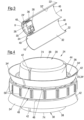
- Fig. 4 shows a schematic view of the piston 24, 24'.
- Each film bag retainer 28, 30 has the central part 38 surrounded by the ring recess 36 and the collar 34 facing the central part 38.
- Three slots 42 extend from a radial outer side of the collar 34 through the ring recess 36 towards the central part 38 of the film bag retainer 28, 30.
- the slots 42 extend into a sidewall 44 of the central part 38 up to a front face 74 of the respective film bag retainer 28, 30.
- the slots 42 divide the collar 34 into respective collar sections 34'. It should be noted in this connection that the slots 42 do not have to present at the sidewall 44 or they could also only extend e.g. part of the way of a height of the sidewall, in particular e.g. 30 % to 70% of the height of the sidewall 44 transverse to the recess 36.
- the plurality of slots 42 separating the plurality of collar sections 34' may have a non-uniform shape, i.e. the slots 42 may not have walls that extend in parallel to one another as shown in Fig. 3 , but the walls of the slots 42 may taper apart either in the direction towards the sidewall from the radial outer side or in a direction facing away from the sidewall 44. It is also conceivable that the slots 42 may comprise first and second slot sections (not shown), with a spacing between the first slot sections being smaller than a spacing between the second slot sections.
- first slot section is smaller than the second slot section, with the first slot section preferably being arranged further towards the outer circumference of the piston 24, 24' than the second slot section.
- slots 42 and/or the ring recess 36 is/are not specifically limited to their specific shape and form and they may be formed such that they have a polygonal, rectangular, triangular, U-shaped, V-shaped etc. cross-section in the radial direction of the first and second film bag retainers 28, 30 extending transverse to the sidewall 44.
- the number of slots is not specifically limited and may be 3 to 30, typically 3 to 24.
- a thickness of the respective collar section 34' is important. If the thickness is too thin the collar section 34' may be too fragile or breakable, if it is too thick it will not be easily moveable. Thus the typical thicknesses of the collar sections 34' will be on the order of mm's, for example 2 mm or less or 0.8 to 1.5 mm in thickness.
- the geometric form of the respective collar section 34' is not specifically limited, and it may be polygonal, rectangular, pentagonal, square, hexagonal, octagonal, or triangular etc.
- the number of collar sections 34' is also not specifically limited and typically may vary from 3 to 30, in particular 3 to 24.
- the trade-off is that the dies and injection molding equipment required to produce such a piston 24, 24' are more complicated in comparison to pistons 24, 24' having a smaller number of collar sections 34'.
- Each of the respective collar sections 34' is moveable relative to the piston head and the piston body 26 and the central part 28, 30.
- the collar sections 34' are in particular resilient or flexible and moveable relative to the piston body 26 and the central part 28, 30 without breaking, and are typically embodied to be movable based on a force of inserting these into the sleeve mechanically by hand, although one could potentially use compressed air (e.g. 6.9 bar) for assistance.
- a base 48 of the ring recess 36 is spaced apart from the piston body 26 by a gap 46.
- the gap 46 may have a height selected in the range of 0.7 to 2 mm.
- this gap 46 is namely selected to ensure that none of the collar sections 34' is bent over too much and thus eventually breaks away from the piston 24, 24' during the movement of the piston 24, 24' towards the head part 6, 7 on dispensing material from the film bag cartridge 1. In this way the piston body 26 acts as a support for the plurality of collar sections 34' when these are deflected towards the piston body 26 on dispensing materials from the film bag cartridge 1.
- the piston 24, 24' is an injection molded part injection molded from one or more materials, in particular one of POM, PTFE, PA or a polymer or a thermoset material having a hardness measured with the Shore D Durometer selected in the range of 55D to 100D.
- each collar section 34' may comprise one or more recesses (not shown) on an inner surface thereof facing the sidewall 44.
- the recesses may also be formed on an outer portion of the collar section 34' facing away from the sidewall 44. It is to be understood, that the outer portion of the collar section may also be formed without a recess.
- the piston body 26 may comprise a plurality of guide structures.
- the guide structures are presently formed as axially aligned ribs 50 protruding from the piston body 26.
- the ribs 50 could be configured to engage corresponding channels (not shown) present in the sleeve 22, 22'.
- the guide structures of the piston 24, 24' may also be formed as channels, if the inner surface 32, 32' of the sleeve 22, 22' comprises corresponding protrusions (also not shown).
- the sleeve 22, 22' may be formed without such guide structures and simply have the inner wall 32, 32' formed without recesses or protrusions as currently shown in Fig. 2 .
- piston 24, 24' may be formed without such guide structures.
- Fig. 5 shows an exploded view of a further piston 24, with the first and second retainers 28, 30 being separate from the piston body 26.
- the piston 24 comprises twenty collar sections 34' in comparison to the piston 24 of Fig. 3 .
- the piston body 26 has a disc shaped part 52 and first and second projections 54, 56 projecting from the piston body 26 at opposite sides of the body 26 in the direction of the film bag retainers 28, 30.
- the disc shaped part 52 of the piston body 26 comprises a base plate 58 and a plurality of webs 60 arranged at either side of the base plate 58.
- the plurality of webs 60 extend radially inwardly from an outer circumferential wall 62 of the disc shaped part 52 of the piston body 26.
- the webs 60 may extend over 20 to 100 % of a length of the disc shaped part 52 between the first and second projections 54, 56 and the outer circumferential wall 62. In the present example the webs extend over 40% of the length of the disc shaped part 52.
- the plurality of webs 60 can namely strengthen both the piston body 26 and the outer circumferential wall 60 of the piston body 26 such that the piston body 26 is formed less flexible than the collar 34 of the respective first and second retainer 28, 30.
- a plurality of apertures 64 arranged at the disc shaped part 52 of the piston body 26.
- the plurality of apertures 64 provide the possibility of enabling an exchange of air at the piston 24 on using the piston 24 in the dispensing assembly 20.
- Fig. 6 shows a schematic sectional view of the piston of Fig. 5 along the sectional line A:A.
- the first and second projections 54, 56 are ring-shaped projections.
- the first and second film bag retainers 28, 30 comprises a central projection 66 projecting towards the piston body 26.
- the central projection 66 cooperates with a respective one of the first and second projections 54, 56 by engaging one of the two central apertures 68 of the respective ring shaped projection 54, 56.
- the film bag retainers 28, 30 is received via a snap-fit connection present between central projection 66 and the central aperture 68.
- the snap-fit connection being formed by an annular groove 70 present at the central aperture 68 cooperating with a circumferential lip 72 present at the central projection 66.
- the groove could also be present at the central projection 66 and the circumferential lip could be present at the central aperture 68.
- each film bag retainer 28, 30 is received via one of a friction fit or a press-fit connection at the piston body 26. It is also conceivable that the piston 24 is made in one piece e.g. in an injection molding process or a 3D printing process and hence that no central projection cooperating with a central aperture is provided.
- a material of the film bag retainer 28, 30 can be different from a material of the piston body 26, or it can be made from the same material as the piston body 26.
- the collars 34 of the first and second film bag retainers 28, 30 have to be designed such that they are more flexible than a material of the piston body 26 in order to enable a relative movement between the collar 34 and the piston body 26.
- the central parts 38 of the film bag retainers 28, 30 comprises the front face 74 remote from the piston body 26, with the front face 74 forming a flat plane or an at least substantially flat plane.
- the front face 74 projects by 20% to 75% of a height of the film bag retainer 28, 30 beyond a height of the collar 34, with the height of the film bag retainer 28, 30 being measured between the front face 74 and a base 48' of the film bag retainer 28, 30 remote from the front face 74, said base 48' facing the piston body 26.
- the first and second film bag retainers 28, 30 also comprise a plurality of support webs 74' arranged at a side of the central part 38 that is remote from the front face 74, i.e. at the side of the film bag retainer 28, 30 having the central projection 66.
- an outermost diameter of the collar 34 is preferably equal to an outermost diameter of the piston body 26. It should be noted that it is also possible that the outermost diameter of the collar 34 is selected in the range of 95% to 105% of the outermost diameter of the piston body 26.
- the piston 24, 24' may have an outermost diameter selected in the range of 1 cm to 30, in particular 1.5 to 15 cm, especially 2 to 10 cm; and/or a height measured between the front faces 74 of the first and second film bag retainers 28, 30 selected in the range of 0.5 to 7 cm in particular 1 to 5 cm.
- Fig. 7 shows a dispenser 76 in which the dispensing assembly 20 installed in a reception space 80 thereof.
- the mixing element 78 is connected to the outlet part 16 of the dispensing assembly 20. Only part of the mixing element 78 is visible in the drawing of Fig. 7 .
- the dispenser comprises two push rods 82, with the push rods 82 being configured to move the respective piston 24, 24' to and fro along the dispensing axis D of the respective push rod 82, wherein said push rods 82 can be coupled to said piston 24, 24' or is fixedly connected to said piston 24, 24'.
- the push rods 82 move the pistons 24, 24' along the dispensing axis D of the reusable film bag cartridge 1, the front face 74 facing away from the piston base 26 pushes against the film bag cartridge 1, thereby urging the material stored inside the film bag cartridge 1 out of the outlet part 16 and through the mixing element 78.
- the push rods 82 are moved via a movement mechanism (not shown) arranged within the dispenser body 84 on actuation of the trigger lever 86 relative to the handle 88.
- the dispenser 76 further comprises an end support 90 arranged at an end of the push rods 82.
Landscapes
- Engineering & Computer Science (AREA)
- Mechanical Engineering (AREA)
- Containers And Packaging Bodies Having A Special Means To Remove Contents (AREA)
Claims (14)
- Piston (24, 24') pour un manchon de support (22, 22') d'un assemblage de distribution (20), en particulier comprenant une ou plusieurs cartouches à sachet film (1), le piston (24, 24') ayant une forme extérieure au moins sensiblement cylindrique et comprenant un corps de piston (26) ainsi qu'un premier et un second moyen de retenue de sachet film (28, 30) agencés au niveau de côtés opposés du corps de piston (26), dans lequel le corps de piston (26) a une partie en forme de disque (52) et une première et une seconde projection (54, 56) se projetant depuis le corps de piston (26) au niveau de côtés opposés du corps de piston (26) dans la direction des moyens de retenue de sachet film (28, 30),
caractérisé en ce que
la première et la seconde projection (54, 56) sont des projections de forme annulaire, dans lequel chacun des moyens de retenue de sachet film (28, 30) comprend une projection centrale (66) se projetant vers le corps de piston (26), et dans lequel la projection centrale (66) coopère avec une projection respective de la première et de la seconde projection (54, 56). - Piston (24, 24') selon la revendication 1, dans lequel le piston (24, 24') est configuré pour une utilisation avec une cartouche à sachet film (1) et chacun du premier du second moyen de retenue de sachet film (28, 30) est configuré pour interagir, en particulier directement, avec ladite cartouche à sachet film (1).
- Piston (24, 24') selon la revendication 1 ou 2, dans lequel la partie en forme de disque (52) comprend des nervures au niveau de sa surface circonférentielle extérieure (62).
- Piston (24, 24') selon l'une quelconque des revendications précédentes, dans lequel la projection centrale (66) coopère avec une ouverture centrale (68) de la projection de forme annulaire (54, 56).
- Piston (24, 24') selon l'une quelconque des revendications précédentes, dans lequel chaque moyen de retenue de sachet film (28, 30) est reçu via l'une d'une connexion à ajustement serré, d'une connexion à ajustement par friction ou d'une connexion à ajustement par encliquetage au niveau du corps de piston (26).
- Piston (24, 24') selon l'une quelconque des revendications précédentes, dans lequel le premier et le second moyen de retenue de sachet film (28, 30) sont formés à partir de matériaux plus flexibles qu'un matériau du corps de piston (26).
- Piston (24, 24') selon l'une quelconque des revendications précédentes, dans lequel le premier et le second moyen de retenue de sachet film (28, 30) comprennent des composants (34, 34)' conçus comme étant plus flexibles que des parties du corps de piston (26).
- Piston (24, 24') selon l'une quelconque des revendications précédentes, dans lequel le premier et le second moyen de retenue de sachet film (28, 30) a une partie centrale (38) entourée par un évidement annulaire (36) et un collier (34) faisant face à la partie centrale (38).
- Piston (24, 24') selon la revendication 8, dans lequel au moins le collier (34) et l'évidement annulaire (36) et en option une paroi latérale (44) de la partie centrale (38) comprennent trois ou plusieurs fentes (42) qui s'étendent depuis un côté radialement extérieur du collier (34) vers la partie centrale (38) du moyen de retenue de sachet film (28, 30).
- Piston (24, 24') selon la revendication 8 ou 9, dans lequel une base (48) de l'évidement (36) est espacée du corps de piston (26) par un intervalle (46), en option dans lequel l'intervalle (46) a une hauteur sélectionnée dans la plage de 0,7 à 2 mm.
- Piston (24, 24') selon l'une des revendications 8 à 10, dans lequel une surface du collier (34) faisant face à la partie centrale (38) comprend un ou plusieurs évidements et/ou une ou plusieurs projections.
- Piston (24, 24') selon l'une des revendications 8 à 11, dans lequel la partie centrale (38) du moyen de retenue de sachet film (28, 30) comprend une face avant (74) éloignée du corps de piston (26), la face avant (74) formant un plan plat ou un plan au moins sensiblement plat, et/ou
dans lequel la face avant (74) se projette à raison de 20 % à 75 % d'une hauteur du moyen de retenue de sachet film (28, 30) au-delà d'une hauteur du collier (34), la hauteur du moyen de retenue de sachet film (28, 30) étant mesurée entre la face avant (74) et une base (48') du moyen de retenue de sachet film (28, 30) éloignée de la face avant (74), ladite base faisant face au corps de piston (26). - Assemblage de distribution comprenant une ou plusieurs cartouches à sachet film (1), un ou plusieurs manchons (22, 22') logeant une cartouche respective parmi lesdites une ou plusieurs cartouches à sachet film (1) et un ou plusieurs pistons (24, 24') selon l'une au moins des revendications précédentes logé dans un manchon respectif parmi lesdits un ou plusieurs manchons (22, 22'), avec en option chacune desdites une ou plusieurs cartouches à sachet film (1) étant remplie avec un matériau (M, M'), plus spécialement un matériau mastic.
- Distributeur comprenant un ou plusieurs pistons selon l'une au moins des revendications 1 à 12 précédentes, une ou plusieurs tiges de poussée, chacune desdites une ou plusieurs tiges de poussée (82) étant configurée pour déplacer l'un desdits pistons (24, 24') d'avant en arrière le long d'un axe de distribution (D) de la tige de poussée respective (82), dans lequel lesdites une ou plusieurs tiges de poussée (82) peuvent être couplées audit piston respectif (24, 24') ou sont connectées de manière fixe audit piston respectif (24, 24').
Applications Claiming Priority (2)
| Application Number | Priority Date | Filing Date | Title |
|---|---|---|---|
| EP19165177.7A EP3714994A1 (fr) | 2019-03-26 | 2019-03-26 | Piston, cartouche, distributeur |
| PCT/EP2020/053229 WO2020192995A1 (fr) | 2019-03-26 | 2020-02-10 | Piston, cartouche, distributeur |
Publications (2)
| Publication Number | Publication Date |
|---|---|
| EP3917686A1 EP3917686A1 (fr) | 2021-12-08 |
| EP3917686B1 true EP3917686B1 (fr) | 2024-11-27 |
Family
ID=65991602
Family Applications (2)
| Application Number | Title | Priority Date | Filing Date |
|---|---|---|---|
| EP19165177.7A Withdrawn EP3714994A1 (fr) | 2019-03-26 | 2019-03-26 | Piston, cartouche, distributeur |
| EP20702839.0A Active EP3917686B1 (fr) | 2019-03-26 | 2020-02-10 | Piston, cartouche, distributeur |
Family Applications Before (1)
| Application Number | Title | Priority Date | Filing Date |
|---|---|---|---|
| EP19165177.7A Withdrawn EP3714994A1 (fr) | 2019-03-26 | 2019-03-26 | Piston, cartouche, distributeur |
Country Status (4)
| Country | Link |
|---|---|
| US (1) | US11938506B2 (fr) |
| EP (2) | EP3714994A1 (fr) |
| CN (1) | CN113573819A (fr) |
| WO (1) | WO2020192995A1 (fr) |
Families Citing this family (5)
| Publication number | Priority date | Publication date | Assignee | Title |
|---|---|---|---|---|
| EP3632575A1 (fr) * | 2018-10-02 | 2020-04-08 | Sulzer Mixpac AG | Piston de cartouche réutilisable |
| EP3826940B1 (fr) * | 2018-10-02 | 2024-04-10 | medmix Switzerland AG | Cartouche, ensemble de distribution et procédé de fabrication d'une cartouche |
| EP3714994A1 (fr) * | 2019-03-26 | 2020-09-30 | Sulzer Mixpac AG | Piston, cartouche, distributeur |
| EP4228824A1 (fr) * | 2020-10-13 | 2023-08-23 | PRC-Desoto International, Inc. | Plongeurs pour cartouches de distribution de produit d'étanchéité ayant un emballage de produit d'étanchéité pliable |
| US20240391678A1 (en) * | 2021-07-22 | 2024-11-28 | Medmix Switzerland Ag | Foil cartridge, support sleeve and cartridge system |
Family Cites Families (51)
| Publication number | Priority date | Publication date | Assignee | Title |
|---|---|---|---|---|
| US1014353A (en) | 1899-07-01 | 1912-01-09 | United Shoe Machinery Ab | Work-support. |
| DE8705030U1 (de) * | 1986-07-30 | 1987-06-04 | Ara-Werk Krämer GmbH + Co, 7441 Unterensingen | Vorrichtung zum strangförmigen Austragen von pastösen Massen |
| GB2197425B (en) * | 1986-11-12 | 1990-02-28 | Metal Box Plc | Pistons for pressure-dispensing containers |
| FR2646790B1 (fr) * | 1989-05-09 | 1991-10-04 | Corso Dominique | Perfectionnements aux pistolets destines a l'extrusion de produits pateux |
| DE9210832U1 (de) | 1992-08-13 | 1993-12-16 | Prestele, Eugen, 86161 Augsburg | Kolben aus Kunststoff |
| US5301835A (en) * | 1992-09-17 | 1994-04-12 | Dow Corning Corporation | Adapter for dispensing material from a sausage type package |
| DE4231421A1 (de) * | 1992-09-19 | 1994-03-24 | Hilti Ag | Kassette und aushärtbare Mörtelmassen enthaltende Beutel |
| DE4231420A1 (de) * | 1992-09-19 | 1994-03-24 | Hilti Ag | Kolben für Auspressgeräte |
| US5443181A (en) * | 1992-09-19 | 1995-08-22 | Hilti Aktiengesellschaft | Cartridge and piston for dispensing mass |
| PH31484A (en) * | 1992-12-22 | 1998-11-03 | Hosokawa Yoko Kk | Container, method of manufacturing the same and installation jig for cartridge container for d18scharge gun. |
| FR2713060B1 (fr) | 1993-11-29 | 1996-02-02 | Oreal | Dispositif applicateur pour liquide. |
| CN1108960C (zh) | 1997-03-31 | 2003-05-21 | 普罗克特和甘保尔公司 | 提供良好产品排出的多层塑料容器 |
| AU2002215704B2 (en) * | 2000-12-22 | 2005-07-28 | Selleys Pty Limited | Dispensing apparatus |
| AUPR248700A0 (en) * | 2000-12-22 | 2001-02-01 | Selleys Pty Limited | Dispensing apparatus |
| JP2002225488A (ja) | 2001-01-31 | 2002-08-14 | Pentel Corp | 塗布具 |
| US6984063B2 (en) | 2002-10-07 | 2006-01-10 | Advanced Biomaterial Systems, Inc. | Apparatus for mixing and dispensing components |
| US6976608B2 (en) * | 2002-07-19 | 2005-12-20 | Hosokawa Yoko Co., Ltd. | Cartridge charged with fluid materials and device for loading such cartridge to fluid dispensing apparatuses |
| US7690530B2 (en) * | 2005-05-06 | 2010-04-06 | Albion Engineering Company | Dispenser for viscous material |
| US8087550B2 (en) * | 2006-04-07 | 2012-01-03 | Albion Engineering Company | Convertible device for dispensing material having parts that can be retained on the device |
| DE102006047289B4 (de) * | 2006-10-06 | 2008-09-04 | Sulzer Chemtech Ag | Kartuschenkolben |
| DE202007016706U1 (de) * | 2007-11-28 | 2009-04-09 | Inatec Gmbh | Kolbenabstreifplatte für Auspresseinrichtung für Beutelschmelzer sowie damit verbundener Beutelschmelzer |
| US8424727B2 (en) * | 2008-05-05 | 2013-04-23 | Meritool Llc | Material dispensing assembly |
| DE102008022999A1 (de) | 2008-05-09 | 2009-11-12 | Fischerwerke Gmbh & Co. Kg | Kolben für eine Kartusche und Kartusche |
| DE102008063502A1 (de) * | 2008-12-17 | 2010-06-24 | Fischbach Kg Kunststoff-Technik | Auspresswerkzeug |
| WO2011080543A1 (fr) | 2009-12-31 | 2011-07-07 | Becton Dickinson France | Composants médicaux à surfaces revêtues présentant un frottement réduit et/ou une faible perméabilité au gaz/liquide |
| EP2468415A1 (fr) * | 2010-12-24 | 2012-06-27 | Sika Technology AG | Dispositif de dosage et de mélange pour matières à plusieurs composants |
| DE102011102524A1 (de) * | 2011-05-26 | 2012-11-29 | Krallmann Kunststoffverarbeitung Gmbh | Spender |
| KR101968608B1 (ko) * | 2011-10-17 | 2019-04-12 | 술저 믹스팩 아게 | 카트리지 및 다성분 카트리지 |
| WO2013078036A1 (fr) * | 2011-11-22 | 2013-05-30 | 3M Innovative Properties Company | Article et procédé de fermeture d'un récipient pliable |
| KR20150013275A (ko) * | 2012-05-14 | 2015-02-04 | 술저 믹스팩 아게 | 다성분 카트리지, 다성분 카트리지를 위한 분배 장치, 및 유동성 성분들을 혼합해서 분무하기 위한 시스템 |
| US9878335B2 (en) * | 2012-05-14 | 2018-01-30 | Sulzer Mixpac Ag | Spray mixer for mixing and spraying at least two flowable components |
| US9579686B2 (en) * | 2012-10-29 | 2017-02-28 | Nordson Corporation | Fluid dispensing assemblies and methods of dispensing fluids from containers |
| US9469061B2 (en) | 2013-01-30 | 2016-10-18 | Plas-Pak Industries Inc | One-piece ventable piston for a dispensing apparatus, a dispensing apparatus with same, and method of making same |
| EP2868393A1 (fr) * | 2013-10-29 | 2015-05-06 | Sulzer Mixpac AG | Coulisseau d'extraction, dispositif d'extraction comprenant le coulisseau d'extraction et procédé |
| US9527106B2 (en) * | 2013-10-31 | 2016-12-27 | Nordson Corporation | Applicator and method for dispensing a viscous fluid |
| US9302289B2 (en) * | 2014-03-04 | 2016-04-05 | Nordson Corporation | Dispensing devices for use with side-by-side fluid cartridges and related methods |
| EP2927156A1 (fr) * | 2014-03-31 | 2015-10-07 | Sulzer Mixpac AG | Cartouche et procédé de fabrication d'une cartouche |
| EP2977023A1 (fr) | 2014-07-24 | 2016-01-27 | 3M Innovative Properties Company | Récipient de stockage et de distribution d'un liquide |
| EP2998030A1 (fr) * | 2014-09-17 | 2016-03-23 | Sulzer Mixpac AG | Piston destiné à une cartouche, cartouche et procédé pour purger l'air d'une cartouche |
| ES2698549T3 (es) * | 2016-07-01 | 2019-02-05 | Sulzer Mixpac Ag | Cartucho, núcleo, molde y método de fabricación de un cartucho |
| EP3263483A1 (fr) * | 2016-07-01 | 2018-01-03 | Sulzer Mixpac AG | Cartouche, noyau, moule et procédé de fabrication d'une cartouche |
| US10968031B2 (en) * | 2017-12-27 | 2021-04-06 | Sulzer Mixpac Ag | Piston for a collapsible cartridge |
| EP4613387A3 (fr) * | 2018-09-19 | 2025-11-19 | PRC-Desoto International, Inc. | Ensembles tête de piston expansible pour pistolets de distribution de produit d'étanchéité |
| US10434528B1 (en) * | 2018-10-02 | 2019-10-08 | Sulzer Mixpac Ag | Cartridge, dispensing assembly and method of manufacturing a cartridge |
| US10870127B2 (en) * | 2018-10-02 | 2020-12-22 | Sulzer Mixpac Ag | Cartridge for a mixing and dispensing system |
| EP3632817A1 (fr) * | 2018-10-02 | 2020-04-08 | Sulzer Mixpac AG | Cartouche, procédé de fabrication d'une cartouche et procédé d'utilisation d'une cartouche |
| US10906702B2 (en) * | 2018-10-02 | 2021-02-02 | Sulzer Mixpac Ag | Cartridge, method of manufacturing a cartridge, dispensing assembly and method of assembling a dispensing assembly |
| EP3632575A1 (fr) * | 2018-10-02 | 2020-04-08 | Sulzer Mixpac AG | Piston de cartouche réutilisable |
| EP3714994A1 (fr) * | 2019-03-26 | 2020-09-30 | Sulzer Mixpac AG | Piston, cartouche, distributeur |
| EP3756756A1 (fr) * | 2019-06-28 | 2020-12-30 | Sulzer Mixpac AG | Mélangeur, procédé de fabrication d'un mélangeur, ensemble de distribution et procédé de distribution de matériaux |
| US12338053B2 (en) * | 2019-07-29 | 2025-06-24 | Medmix Switzerland Ag | Cartridge and connector for a cartridge |
-
2019
- 2019-03-26 EP EP19165177.7A patent/EP3714994A1/fr not_active Withdrawn
-
2020
- 2020-02-10 EP EP20702839.0A patent/EP3917686B1/fr active Active
- 2020-02-10 WO PCT/EP2020/053229 patent/WO2020192995A1/fr not_active Ceased
- 2020-02-10 US US17/442,714 patent/US11938506B2/en active Active
- 2020-02-10 CN CN202080024283.7A patent/CN113573819A/zh active Pending
Also Published As
| Publication number | Publication date |
|---|---|
| WO2020192995A1 (fr) | 2020-10-01 |
| EP3917686A1 (fr) | 2021-12-08 |
| CN113573819A (zh) | 2021-10-29 |
| US11938506B2 (en) | 2024-03-26 |
| US20220184654A1 (en) | 2022-06-16 |
| EP3714994A1 (fr) | 2020-09-30 |
Similar Documents
| Publication | Publication Date | Title |
|---|---|---|
| EP3917686B1 (fr) | Piston, cartouche, distributeur | |
| KR102628212B1 (ko) | 재사용 가능한 카트리지 피스톤 | |
| US6705756B2 (en) | Apparatus and method for mixing and dispensing components of a composition | |
| EP3983136B1 (fr) | Ensemble cartouche, système et procédé d'assemblage d'ensemble cartouche | |
| US10080882B2 (en) | Valved container assembly | |
| JP6042421B2 (ja) | 液体製品ディスペンサ | |
| US20140021225A1 (en) | Dispensing pen | |
| KR20100059895A (ko) | 분배 장치 | |
| US20100237104A1 (en) | Cove Base Nozzle for Dispensing Applications | |
| TW202241591A (zh) | 分配器、匣組件、支撐套筒及操作分配器的方法 | |
| US11596972B2 (en) | Coaxial cartridge for multi-component materials and method of assembling a coaxial cartridge | |
| JP2023515274A (ja) | 物質分配器及び物質分配器を提供する方法 | |
| EP3771497A1 (fr) | Ensemble de cartouche, manchon, système et procédé d'assemblage d'un ensemble de cartouche |
Legal Events
| Date | Code | Title | Description |
|---|---|---|---|
| STAA | Information on the status of an ep patent application or granted ep patent |
Free format text: STATUS: UNKNOWN |
|
| STAA | Information on the status of an ep patent application or granted ep patent |
Free format text: STATUS: THE INTERNATIONAL PUBLICATION HAS BEEN MADE |
|
| PUAI | Public reference made under article 153(3) epc to a published international application that has entered the european phase |
Free format text: ORIGINAL CODE: 0009012 |
|
| STAA | Information on the status of an ep patent application or granted ep patent |
Free format text: STATUS: REQUEST FOR EXAMINATION WAS MADE |
|
| 17P | Request for examination filed |
Effective date: 20210831 |
|
| AK | Designated contracting states |
Kind code of ref document: A1 Designated state(s): AL AT BE BG CH CY CZ DE DK EE ES FI FR GB GR HR HU IE IS IT LI LT LU LV MC MK MT NL NO PL PT RO RS SE SI SK SM TR |
|
| RAP3 | Party data changed (applicant data changed or rights of an application transferred) |
Owner name: MEDMIX SWITZERLAND AG |
|
| DAV | Request for validation of the european patent (deleted) | ||
| DAX | Request for extension of the european patent (deleted) | ||
| P01 | Opt-out of the competence of the unified patent court (upc) registered |
Effective date: 20230505 |
|
| GRAP | Despatch of communication of intention to grant a patent |
Free format text: ORIGINAL CODE: EPIDOSNIGR1 |
|
| STAA | Information on the status of an ep patent application or granted ep patent |
Free format text: STATUS: GRANT OF PATENT IS INTENDED |
|
| INTG | Intention to grant announced |
Effective date: 20240627 |
|
| GRAS | Grant fee paid |
Free format text: ORIGINAL CODE: EPIDOSNIGR3 |
|
| GRAA | (expected) grant |
Free format text: ORIGINAL CODE: 0009210 |
|
| STAA | Information on the status of an ep patent application or granted ep patent |
Free format text: STATUS: THE PATENT HAS BEEN GRANTED |
|
| AK | Designated contracting states |
Kind code of ref document: B1 Designated state(s): AL AT BE BG CH CY CZ DE DK EE ES FI FR GB GR HR HU IE IS IT LI LT LU LV MC MK MT NL NO PL PT RO RS SE SI SK SM TR |
|
| REG | Reference to a national code |
Ref country code: GB Ref legal event code: FG4D |
|
| REG | Reference to a national code |
Ref country code: CH Ref legal event code: EP |
|
| REG | Reference to a national code |
Ref country code: IE Ref legal event code: FG4D |
|
| REG | Reference to a national code |
Ref country code: DE Ref legal event code: R096 Ref document number: 602020041993 Country of ref document: DE |
|
| REG | Reference to a national code |
Ref country code: LT Ref legal event code: MG9D |
|
| REG | Reference to a national code |
Ref country code: NL Ref legal event code: MP Effective date: 20241127 |
|
| PG25 | Lapsed in a contracting state [announced via postgrant information from national office to epo] |
Ref country code: HR Free format text: LAPSE BECAUSE OF FAILURE TO SUBMIT A TRANSLATION OF THE DESCRIPTION OR TO PAY THE FEE WITHIN THE PRESCRIBED TIME-LIMIT Effective date: 20241127 Ref country code: PT Free format text: LAPSE BECAUSE OF FAILURE TO SUBMIT A TRANSLATION OF THE DESCRIPTION OR TO PAY THE FEE WITHIN THE PRESCRIBED TIME-LIMIT Effective date: 20250327 Ref country code: IS Free format text: LAPSE BECAUSE OF FAILURE TO SUBMIT A TRANSLATION OF THE DESCRIPTION OR TO PAY THE FEE WITHIN THE PRESCRIBED TIME-LIMIT Effective date: 20250327 |
|
| PG25 | Lapsed in a contracting state [announced via postgrant information from national office to epo] |
Ref country code: NL Free format text: LAPSE BECAUSE OF FAILURE TO SUBMIT A TRANSLATION OF THE DESCRIPTION OR TO PAY THE FEE WITHIN THE PRESCRIBED TIME-LIMIT Effective date: 20241127 Ref country code: FI Free format text: LAPSE BECAUSE OF FAILURE TO SUBMIT A TRANSLATION OF THE DESCRIPTION OR TO PAY THE FEE WITHIN THE PRESCRIBED TIME-LIMIT Effective date: 20241127 |
|
| REG | Reference to a national code |
Ref country code: AT Ref legal event code: MK05 Ref document number: 1745234 Country of ref document: AT Kind code of ref document: T Effective date: 20241127 |
|
| PG25 | Lapsed in a contracting state [announced via postgrant information from national office to epo] |
Ref country code: BG Free format text: LAPSE BECAUSE OF FAILURE TO SUBMIT A TRANSLATION OF THE DESCRIPTION OR TO PAY THE FEE WITHIN THE PRESCRIBED TIME-LIMIT Effective date: 20241127 |
|
| PG25 | Lapsed in a contracting state [announced via postgrant information from national office to epo] |
Ref country code: ES Free format text: LAPSE BECAUSE OF FAILURE TO SUBMIT A TRANSLATION OF THE DESCRIPTION OR TO PAY THE FEE WITHIN THE PRESCRIBED TIME-LIMIT Effective date: 20241127 |
|
| PG25 | Lapsed in a contracting state [announced via postgrant information from national office to epo] |
Ref country code: NO Free format text: LAPSE BECAUSE OF FAILURE TO SUBMIT A TRANSLATION OF THE DESCRIPTION OR TO PAY THE FEE WITHIN THE PRESCRIBED TIME-LIMIT Effective date: 20250227 |
|
| PG25 | Lapsed in a contracting state [announced via postgrant information from national office to epo] |
Ref country code: LV Free format text: LAPSE BECAUSE OF FAILURE TO SUBMIT A TRANSLATION OF THE DESCRIPTION OR TO PAY THE FEE WITHIN THE PRESCRIBED TIME-LIMIT Effective date: 20241127 Ref country code: GR Free format text: LAPSE BECAUSE OF FAILURE TO SUBMIT A TRANSLATION OF THE DESCRIPTION OR TO PAY THE FEE WITHIN THE PRESCRIBED TIME-LIMIT Effective date: 20250228 Ref country code: AT Free format text: LAPSE BECAUSE OF FAILURE TO SUBMIT A TRANSLATION OF THE DESCRIPTION OR TO PAY THE FEE WITHIN THE PRESCRIBED TIME-LIMIT Effective date: 20241127 |
|
| PG25 | Lapsed in a contracting state [announced via postgrant information from national office to epo] |
Ref country code: PL Free format text: LAPSE BECAUSE OF FAILURE TO SUBMIT A TRANSLATION OF THE DESCRIPTION OR TO PAY THE FEE WITHIN THE PRESCRIBED TIME-LIMIT Effective date: 20241127 |
|
| PGFP | Annual fee paid to national office [announced via postgrant information from national office to epo] |
Ref country code: FR Payment date: 20250224 Year of fee payment: 6 |
|
| PGFP | Annual fee paid to national office [announced via postgrant information from national office to epo] |
Ref country code: GB Payment date: 20250220 Year of fee payment: 6 |
|
| PG25 | Lapsed in a contracting state [announced via postgrant information from national office to epo] |
Ref country code: RS Free format text: LAPSE BECAUSE OF FAILURE TO SUBMIT A TRANSLATION OF THE DESCRIPTION OR TO PAY THE FEE WITHIN THE PRESCRIBED TIME-LIMIT Effective date: 20250227 |
|
| PG25 | Lapsed in a contracting state [announced via postgrant information from national office to epo] |
Ref country code: SM Free format text: LAPSE BECAUSE OF FAILURE TO SUBMIT A TRANSLATION OF THE DESCRIPTION OR TO PAY THE FEE WITHIN THE PRESCRIBED TIME-LIMIT Effective date: 20241127 |
|
| PG25 | Lapsed in a contracting state [announced via postgrant information from national office to epo] |
Ref country code: DK Free format text: LAPSE BECAUSE OF FAILURE TO SUBMIT A TRANSLATION OF THE DESCRIPTION OR TO PAY THE FEE WITHIN THE PRESCRIBED TIME-LIMIT Effective date: 20241127 |
|
| PG25 | Lapsed in a contracting state [announced via postgrant information from national office to epo] |
Ref country code: EE Free format text: LAPSE BECAUSE OF FAILURE TO SUBMIT A TRANSLATION OF THE DESCRIPTION OR TO PAY THE FEE WITHIN THE PRESCRIBED TIME-LIMIT Effective date: 20241127 |
|
| PG25 | Lapsed in a contracting state [announced via postgrant information from national office to epo] |
Ref country code: RO Free format text: LAPSE BECAUSE OF FAILURE TO SUBMIT A TRANSLATION OF THE DESCRIPTION OR TO PAY THE FEE WITHIN THE PRESCRIBED TIME-LIMIT Effective date: 20241127 |
|
| PG25 | Lapsed in a contracting state [announced via postgrant information from national office to epo] |
Ref country code: SK Free format text: LAPSE BECAUSE OF FAILURE TO SUBMIT A TRANSLATION OF THE DESCRIPTION OR TO PAY THE FEE WITHIN THE PRESCRIBED TIME-LIMIT Effective date: 20241127 |
|
| PG25 | Lapsed in a contracting state [announced via postgrant information from national office to epo] |
Ref country code: CZ Free format text: LAPSE BECAUSE OF FAILURE TO SUBMIT A TRANSLATION OF THE DESCRIPTION OR TO PAY THE FEE WITHIN THE PRESCRIBED TIME-LIMIT Effective date: 20241127 |
|
| PG25 | Lapsed in a contracting state [announced via postgrant information from national office to epo] |
Ref country code: IT Free format text: LAPSE BECAUSE OF FAILURE TO SUBMIT A TRANSLATION OF THE DESCRIPTION OR TO PAY THE FEE WITHIN THE PRESCRIBED TIME-LIMIT Effective date: 20241127 |
|
| REG | Reference to a national code |
Ref country code: DE Ref legal event code: R097 Ref document number: 602020041993 Country of ref document: DE |
|
| PG25 | Lapsed in a contracting state [announced via postgrant information from national office to epo] |
Ref country code: SE Free format text: LAPSE BECAUSE OF FAILURE TO SUBMIT A TRANSLATION OF THE DESCRIPTION OR TO PAY THE FEE WITHIN THE PRESCRIBED TIME-LIMIT Effective date: 20241127 |
|
| PG25 | Lapsed in a contracting state [announced via postgrant information from national office to epo] |
Ref country code: MC Free format text: LAPSE BECAUSE OF FAILURE TO SUBMIT A TRANSLATION OF THE DESCRIPTION OR TO PAY THE FEE WITHIN THE PRESCRIBED TIME-LIMIT Effective date: 20241127 |
|
| REG | Reference to a national code |
Ref country code: CH Ref legal event code: PL |
|
| PLBE | No opposition filed within time limit |
Free format text: ORIGINAL CODE: 0009261 |
|
| STAA | Information on the status of an ep patent application or granted ep patent |
Free format text: STATUS: NO OPPOSITION FILED WITHIN TIME LIMIT |
|
| PG25 | Lapsed in a contracting state [announced via postgrant information from national office to epo] |
Ref country code: LU Free format text: LAPSE BECAUSE OF NON-PAYMENT OF DUE FEES Effective date: 20250210 |
|
| PG25 | Lapsed in a contracting state [announced via postgrant information from national office to epo] |
Ref country code: CH Free format text: LAPSE BECAUSE OF NON-PAYMENT OF DUE FEES Effective date: 20250228 |
|
| 26N | No opposition filed |
Effective date: 20250828 |
|
| REG | Reference to a national code |
Ref country code: BE Ref legal event code: MM Effective date: 20250228 |
|
| PG25 | Lapsed in a contracting state [announced via postgrant information from national office to epo] |
Ref country code: BE Free format text: LAPSE BECAUSE OF NON-PAYMENT OF DUE FEES Effective date: 20250228 |
|
| PG25 | Lapsed in a contracting state [announced via postgrant information from national office to epo] |
Ref country code: IE Free format text: LAPSE BECAUSE OF NON-PAYMENT OF DUE FEES Effective date: 20250210 |
|
| PGFP | Annual fee paid to national office [announced via postgrant information from national office to epo] |
Ref country code: DE Payment date: 20260218 Year of fee payment: 7 |