EP3917865B1 - Verbesserte bahnspannungsregelung - Google Patents
Verbesserte bahnspannungsregelung Download PDFInfo
- Publication number
- EP3917865B1 EP3917865B1 EP20748095.5A EP20748095A EP3917865B1 EP 3917865 B1 EP3917865 B1 EP 3917865B1 EP 20748095 A EP20748095 A EP 20748095A EP 3917865 B1 EP3917865 B1 EP 3917865B1
- Authority
- EP
- European Patent Office
- Prior art keywords
- roll
- arm
- tension
- web
- driven roller
- Prior art date
- Legal status (The legal status is an assumption and is not a legal conclusion. Google has not performed a legal analysis and makes no representation as to the accuracy of the status listed.)
- Active
Links
Images


Classifications
-
- B—PERFORMING OPERATIONS; TRANSPORTING
- B65—CONVEYING; PACKING; STORING; HANDLING THIN OR FILAMENTARY MATERIAL
- B65H—HANDLING THIN OR FILAMENTARY MATERIAL, e.g. SHEETS, WEBS, CABLES
- B65H23/00—Registering, tensioning, smoothing or guiding webs
- B65H23/04—Registering, tensioning, smoothing or guiding webs longitudinally
- B65H23/06—Registering, tensioning, smoothing or guiding webs longitudinally by retarding devices, e.g. acting on web-roll spindle
- B65H23/063—Registering, tensioning, smoothing or guiding webs longitudinally by retarding devices, e.g. acting on web-roll spindle and controlling web tension
-
- B—PERFORMING OPERATIONS; TRANSPORTING
- B65—CONVEYING; PACKING; STORING; HANDLING THIN OR FILAMENTARY MATERIAL
- B65H—HANDLING THIN OR FILAMENTARY MATERIAL, e.g. SHEETS, WEBS, CABLES
- B65H23/00—Registering, tensioning, smoothing or guiding webs
- B65H23/04—Registering, tensioning, smoothing or guiding webs longitudinally
- B65H23/048—Registering, tensioning, smoothing or guiding webs longitudinally by positively actuated movable bars or rollers
-
- B—PERFORMING OPERATIONS; TRANSPORTING
- B65—CONVEYING; PACKING; STORING; HANDLING THIN OR FILAMENTARY MATERIAL
- B65H—HANDLING THIN OR FILAMENTARY MATERIAL, e.g. SHEETS, WEBS, CABLES
- B65H23/00—Registering, tensioning, smoothing or guiding webs
- B65H23/04—Registering, tensioning, smoothing or guiding webs longitudinally
- B65H23/042—Sensing the length of a web loop
-
- B—PERFORMING OPERATIONS; TRANSPORTING
- B65—CONVEYING; PACKING; STORING; HANDLING THIN OR FILAMENTARY MATERIAL
- B65H—HANDLING THIN OR FILAMENTARY MATERIAL, e.g. SHEETS, WEBS, CABLES
- B65H23/00—Registering, tensioning, smoothing or guiding webs
- B65H23/04—Registering, tensioning, smoothing or guiding webs longitudinally
- B65H23/044—Sensing web tension
-
- B—PERFORMING OPERATIONS; TRANSPORTING
- B65—CONVEYING; PACKING; STORING; HANDLING THIN OR FILAMENTARY MATERIAL
- B65H—HANDLING THIN OR FILAMENTARY MATERIAL, e.g. SHEETS, WEBS, CABLES
- B65H23/00—Registering, tensioning, smoothing or guiding webs
- B65H23/04—Registering, tensioning, smoothing or guiding webs longitudinally
- B65H23/06—Registering, tensioning, smoothing or guiding webs longitudinally by retarding devices, e.g. acting on web-roll spindle
- B65H23/08—Registering, tensioning, smoothing or guiding webs longitudinally by retarding devices, e.g. acting on web-roll spindle acting on web roll being unwound
- B65H23/085—Registering, tensioning, smoothing or guiding webs longitudinally by retarding devices, e.g. acting on web-roll spindle acting on web roll being unwound and controlling web tension
-
- B—PERFORMING OPERATIONS; TRANSPORTING
- B65—CONVEYING; PACKING; STORING; HANDLING THIN OR FILAMENTARY MATERIAL
- B65H—HANDLING THIN OR FILAMENTARY MATERIAL, e.g. SHEETS, WEBS, CABLES
- B65H23/00—Registering, tensioning, smoothing or guiding webs
- B65H23/04—Registering, tensioning, smoothing or guiding webs longitudinally
- B65H23/18—Registering, tensioning, smoothing or guiding webs longitudinally by controlling or regulating the web-advancing mechanism, e.g. mechanism acting on the running web
- B65H23/188—Registering, tensioning, smoothing or guiding webs longitudinally by controlling or regulating the web-advancing mechanism, e.g. mechanism acting on the running web in connection with running-web
- B65H23/1888—Registering, tensioning, smoothing or guiding webs longitudinally by controlling or regulating the web-advancing mechanism, e.g. mechanism acting on the running web in connection with running-web and controlling web tension
-
- B—PERFORMING OPERATIONS; TRANSPORTING
- B65—CONVEYING; PACKING; STORING; HANDLING THIN OR FILAMENTARY MATERIAL
- B65H—HANDLING THIN OR FILAMENTARY MATERIAL, e.g. SHEETS, WEBS, CABLES
- B65H23/00—Registering, tensioning, smoothing or guiding webs
- B65H23/04—Registering, tensioning, smoothing or guiding webs longitudinally
- B65H23/26—Registering, tensioning, smoothing or guiding webs longitudinally by transverse stationary or adjustable bars or rollers
-
- B—PERFORMING OPERATIONS; TRANSPORTING
- B65—CONVEYING; PACKING; STORING; HANDLING THIN OR FILAMENTARY MATERIAL
- B65H—HANDLING THIN OR FILAMENTARY MATERIAL, e.g. SHEETS, WEBS, CABLES
- B65H2402/00—Constructional details of the handling apparatus
- B65H2402/30—Supports; Subassemblies; Mountings thereof
- B65H2402/31—Pivoting support means
-
- B—PERFORMING OPERATIONS; TRANSPORTING
- B65—CONVEYING; PACKING; STORING; HANDLING THIN OR FILAMENTARY MATERIAL
- B65H—HANDLING THIN OR FILAMENTARY MATERIAL, e.g. SHEETS, WEBS, CABLES
- B65H2408/00—Specific machines
- B65H2408/20—Specific machines for handling web(s)
- B65H2408/21—Accumulators
- B65H2408/217—Accumulators of rollers type, e.g. with at least one fixed and one movable roller
- B65H2408/2171—Accumulators of rollers type, e.g. with at least one fixed and one movable roller the position of the movable roller(s), i.e. the web loop, being positively actuated
-
- B—PERFORMING OPERATIONS; TRANSPORTING
- B65—CONVEYING; PACKING; STORING; HANDLING THIN OR FILAMENTARY MATERIAL
- B65H—HANDLING THIN OR FILAMENTARY MATERIAL, e.g. SHEETS, WEBS, CABLES
- B65H2511/00—Dimensions; Position; Numbers; Identification; Occurrences
- B65H2511/10—Size; Dimensions
- B65H2511/16—Irregularities, e.g. protuberances
- B65H2511/166—Irregularities, e.g. protuberances relative to diameter, eccentricity or circularity
-
- B—PERFORMING OPERATIONS; TRANSPORTING
- B65—CONVEYING; PACKING; STORING; HANDLING THIN OR FILAMENTARY MATERIAL
- B65H—HANDLING THIN OR FILAMENTARY MATERIAL, e.g. SHEETS, WEBS, CABLES
- B65H2511/00—Dimensions; Position; Numbers; Identification; Occurrences
- B65H2511/20—Location in space
- B65H2511/21—Angle
- B65H2511/216—Orientation, e.g. with respect to direction of movement
-
- B—PERFORMING OPERATIONS; TRANSPORTING
- B65—CONVEYING; PACKING; STORING; HANDLING THIN OR FILAMENTARY MATERIAL
- B65H—HANDLING THIN OR FILAMENTARY MATERIAL, e.g. SHEETS, WEBS, CABLES
- B65H2515/00—Physical entities not provided for in groups B65H2511/00 or B65H2513/00
- B65H2515/30—Forces; Stresses
- B65H2515/31—Tensile forces
-
- B—PERFORMING OPERATIONS; TRANSPORTING
- B65—CONVEYING; PACKING; STORING; HANDLING THIN OR FILAMENTARY MATERIAL
- B65H—HANDLING THIN OR FILAMENTARY MATERIAL, e.g. SHEETS, WEBS, CABLES
- B65H2553/00—Sensing or detecting means
- B65H2553/20—Sensing or detecting means using electric elements
-
- B—PERFORMING OPERATIONS; TRANSPORTING
- B65—CONVEYING; PACKING; STORING; HANDLING THIN OR FILAMENTARY MATERIAL
- B65H—HANDLING THIN OR FILAMENTARY MATERIAL, e.g. SHEETS, WEBS, CABLES
- B65H2701/00—Handled material; Storage means
- B65H2701/10—Handled articles or webs
- B65H2701/11—Dimensional aspect of article or web
- B65H2701/113—Size
- B65H2701/1133—Size of webs
- B65H2701/11332—Size of webs strip, tape, narrow web
Definitions
- the current invention relates to apparatuses and methods for controlling tension in a sheet of web material being unwound from a roll of material. More specifically, the current invention relates to a rotary dancer mechanism that may be used to control unwinding of roll material and more particularly an out-of-round roll with improved speed and consistent tension.
- Winders and rewinders are machines that roll lengths of web material, such as paper and nonwoven materials or any other material that may be spirally about a core to form a roll.
- a winder is typically known as an apparatus that performs the very first wind of a web, forming what is generally known as a parent roll.
- a rewinder is typically known as an apparatus that unwinds the parent roll into smaller rolls that represent the finished product. For instance a parent roll of bath tissue may be unwound in a continuous fashion by a rewinder and fed into a process by which the tissue is wound onto cores supported on mandrels to provide individual, relatively small diameter logs of material. The rolled product log material may then be cut to designated lengths into the finalized product.
- other finalized products that may be made by this process include paper towels, paper rolls, nonwoven materials or any other material that may form a parent roll.
- the parent rolls are moved to storage locations until they are consumed in a converting process during which the finalized products are made.
- the handling and storage of the parent rolls may subject the rolls to certain stresses that cause the rolls to become disoriented from a pure cylindrical shape. Storing a parent on a hard surface, for instance, may cause a flat spot on the roll.
- Such rolls can have an elliptical or eccentric shape, often referred to as an out-of-round roll (OOR), depending upon how the roll is handled.
- OOR out-of-round roll
- any out-of-roundness characteristics may cause tension disturbances within the web. These tension disturbances may cause many problems. Differences in tension in the web as the web is fed into a process may cause machine malfunctions, web breaks, and can lead to the production of non-uniform finalized products.
- dancer rolls were inserted into the process between first and second sets of driving rolls or between first and second nips.
- the basic purpose of a dancer roll is to maintain constant tension on the continuous web (or sheet) as the web is fed into a downstream process and traverses a span between first and second sets of driving rolls.
- the dancer roll moves up and down in a track, serving two functions related to stabilizing the tension in the web.
- the dancer roll provides a damping effect on intermediate term disturbances in the tension in the web.
- the dancer roll temporarily absorbs the difference in drive speeds between the first and second sets of driving rolls, until such time as the drive speeds can be appropriately coordinated.
- the dancer roll is suspended on a support system, wherein a generally static force supplied by the support system supports the dancer roll against an opposing force applied by the tension in the web and the weight of the dancer roll. So long as the tension in the web is constant, the dancer roll remains generally centered in its operating window on the track.
- the current invention is generally directed to apparatuses and methods for controlling tension and tension disturbances in a web being continuously unwound from a parent roll, and more particularly, an out-of-round (OOR) roll of spirally wound web material.
- OOR out-of-round
- a rotary dancer mechanism is used for applying active and variable forces to a moving web in response to irregularities, such as variations in tension.
- the web tension control apparatuses and methods of the current invention are an improvement over conventional active and passive dancer rolls, which are generally limited in their ability to control downstream web tension while in motion.
- the rotary dancer of the current invention experiences limited gravitational forces and only limited bearing friction when in use. Additionally, the apparatus of the current invention is a fairly simple design with few moving parts, which is in contrast to conventional active and passive dancer rolls that have a complex set of cable and pulley assemblies.
- the present invention provides a method for controlling tension in a web being unwound from an out-of-round roll of spirally wound web material, as claimed in claim 1.
- the present invention provides a method for controlling tension in a web being fed to a process, as claimed in claim 4.
- the present invention provides an apparatus for unwinding a web, as claimed in claim 8.
- the current invention provides a rotary dancer mechanism for controlling tension and tension disturbances of the web as it is unwound.
- the current invention provides a dancer having a rotatable arm and a non-driven roller to support the web as it is unwound.
- the instant rotary dancer mechanism has extremely fast response times to tension variations. As such, processes incorporating the apparatuses are capable of processing rolls that have a greater degree of eccentricity compared to prior art dancers. The faster response time also enables OOR rolls to be processed at faster speeds in comparison with past apparatuses. Having the capability to process OOR rolls allows manufacturers to produce web materials that contain a greater amount of moisture.
- Allowing the machines to produce a wetter roll allows for higher processing speeds and greater throughput to make the web.
- An additional benefit is that the OOR rolls produced may potentially be double stacked in a warehouse prior to converting. By increasing warehouse capacity, less machine grade changes may be needed.
- the invention provides an improved method of controlling tension variation in a web unwound from an OOR roll using a rotary dancer mechanism having a non-driven roller that is moveable along the longitudinal axis of a rotatable arm.
- the rotatable arm has a rotational speed roughly equivalent to two times the rotational speed of the OOR roll and may be phased to the variation in web tension caused by the eccentricity of the OOR roll.
- the arm may rotate continuously as the OOR roll is unwound and this continuous motion may reduce the acceleration required and therefore the load on the system.
- the rotary dancer mechanism 10 comprises a linkage, referred to herein as a rotatable arm 22, having first and second ends 23, 25 and rotatable about a pivot point 26.
- a roller 20 At a first end 23 of the rotatable arm 22 is a roller 20, which is preferably light weight, low inertia and non-driven.
- the non-driven roller 20 is generally configured to support the web material 12 as it is unwound from a roll.
- a counterweight 48 is disposed opposite the non-driven roller 20 at the second end 25 of the rotatable arm 22.
- the arm 22 is rotated by a rotary drive (not illustrated), which may rotate the arm 22 about a rotary pin.
- a rotary drive (not illustrated), which may rotate the arm 22 about a rotary pin.
- the rotary dancer mechanism 10 stores a certain length of sheet-material web and/or generates a desired level of tensioning in the sheet-material web supported by the roller non-driven roller 20.
- the length of sheet material stored depends on the angle of rotation of the rotatable arm 22 between 0 and more or less 180°.
- the rotatable arm 22 is driven by means of a motor.
- This motor may be a servomotor, or actuating motor, or a stepping motor or a pneumatic drive.
- the pressure by which the drive is driven is regulated preferably in dependence on the angular position of the rotatable arm 22.
- the zero position in which the rotary dancer mechanism 10 stores barely a minimal length of web material 12, if any at all, and the rollers 34, 36 are located, in the present case, below the non-driven roller 20.
- the rotatable arm 22 may be advanced by the motor to a second position (cf. FIG. 4 ) more or less 180° from the first position. In the second position the angle of the web material 12 passes over the rollers 34, 36 and the non-driven roller 20 decreases relative to the first position.
- the rollers 34, 36 move away horizontally from each other and become closer to the non-driven roller 20.
- the position of the rotatable arm 22 may be continuously changed between the first and the second positions in phase with an OOR roll 14 that is being unwound.
- the position of the non-driven roller 20 relative to the pivot point 26 of the rotatable arm 22 may be adjusted.
- the rotary dancer mechanism 10 may comprise an arm 22 having a longitudinal axis 50 and rotatable about a pivot point 26 and a non-driven roller 20 disposed near the first end 23 thereof and movable between the first end 23 and the pivot point 26 along the longitudinal axis 50.
- the position of the non-driven roller 20 may be adjusted as the shape of the roll being unwound changes.
- the non-driven roller 20 may be disposed near the first end 23 of the rotatable arm 22. As the OOR roll 14 is unwound and the difference between the lengths of the major and minor lobes decreases, the non-driven roller 20 may be moved along the longitudinal axis 50 of the rotatable arm 22 towards the pivot point 26.
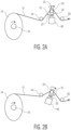
- FIGS. 2A-2D web displacement on the rotary dancer mechanism 10 is illustrated as the rotary dancer mechanism 10 rotates.
- FIGS. 2A-2D shows different positions as the rotary dancer mechanism 10 rotates in a continuous clockwise motion.
- the non-driven roller 20 is positioned adjacent to the first end 23 of the rotatable arm 22.
- the offset of the non-driven roller 20 will adjust toward the rotating assembly center.
- the portion of the non-driven roller 20 relative to the pivot point 26 of the rotatable arm 22, referred to herein as the offset magnitude (D), may be adjusted based on the difference between the major and minor lobe distances. Further, as the OOR roll 14 is unwound and the difference between the major and minor lobe distances changes, the offset magnitude may be adjusted. Eventually, the major and minor lobe distances may be approximately equal and the rotatable arm 22 may stop rotating and the non-driven roller 20 may be fixed in given position.
- the OOR roll 14 comprises a web material 12 spirally wound about a core 11.
- the OOR has major and minor axis 100, 102, also referred to herein as major and minor lobes.
- a high point of the OOR roll 14 is defined by a major lobe tangency 90 and a low point of the OOR roll 14 is defined by a minor lobe tangency 92.
- the major and minor lobe tangencies 90, 92 may be measured using any suitable distance measuring devices including, but are not limited to, lasers, ultrasonic devices, conventional measurement devices, combinations thereof, and the lengths of the major and minor lobes 100, 102 may be determined.
- the lengths of the major and minor lobes 100, 102 may then in-turn be used to calculate the effective diameter of the OOR roll 14 using Equation 1 below, where X is the major lobe length and Y is the minor lobe length.
- R effective X • Y 1 2
- While the current invention is particularly well suited for controlling the tension of a web 12 as it is unwound from an OOR roll 14 it may also be useful in unwinding a substantially round roll such that the major and minor lobe lengths are equal and the OOR roll 14 has an aspect ratio approximately equal to 1.
- a position sensor (not shown) measures the major and minor lobe tangencies 90, 92 and the effective diameter of the roll is determined using Equation 1 shown above.
- a position sensor 42 senses the position of the rotatable arm 22 and the arm 22 is rotated to lock the rotary dancer mechanism 10 to an unwind position.
- a phase offset is calculated dividing the length of web between the major lobe tangency 90 and the non-driven roller 20 by the effective radius.
- the final phasing is a closed loop control based on feedback from a load cell 46 at the discharge of the rotary dancer mechanism 10.
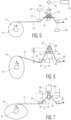
- FIGS. 3-5 one embodiment of a system for controlling the tension of an OOR roll 14 using a rotary dancer mechanism 10 in accordance with the present invention is shown.
- the rotary dancer mechanism 10 is shown as part of a process by which a web material 12 is unwound from the OOR roll 14 and fed downstream.
- the OOR roll 14 in FIG. 3 is an elliptical shape and as the OOR roll 14 is unwound it becomes substantially circular as depicted in FIG. 4 .
- the rotary dancer mechanism 10 is configured to respond to tension variations in the web material 12 so that the web material 12 is fed downstream at a relatively constant tension.
- the OOR roll 14 is unwound from a core 11 using an unwind device 16, such as a motor. Speed of advance of the web material 12 is controlled by the unwind device 16.
- the rotary dancer mechanism 10 includes a non-driven roller 20 disposed on a rotatable arm 22 having a longitudinal axis 50.
- the rotatable arm 22 is attached to a motor, not shown, configured so that a controlled amount of torque is applied to the arm 22 and rotates the arm 22 360° about a pivot point 26.
- the non-driven roller 20 preferably has a low inertia and low weight. The low inertia and weight of the non-driven roller 20 minimizes the drive power to turn the rotatable arm 22.
- a counterweight 48 is disposed on the rotatable arm 22 opposite the non-driven roller 20 so as to balance the rotatable arm 22 as it rotates.
- the counterweight 48 is moveable along the longitudinal axis 50. In embodiments, the counterweight 48 is moved in a direction opposite that of the non-driven roller 20 so as to balance the arm 22 as it is rotated.
- the rotary dancer mechanism 10 may also be placed in association with a first fixed roll 34 and a second fixed roll 36.
- the fixed rolls 34 and 36 may facilitate web displacement when the rotary dancer mechanism 10 rotates.
- the fixed rolls 34 and 36 may be provided with a load sensor and used to facilitate measurements of tension in the web 12.
- the fixed rolls 34, 36 and non-driven roller 20 are arranged such that the web material 12 assumes a serpentine travel path through the rotary dancer mechanism 10.
- torque may be delivered to the rotatable arm 22 and the speed at which the arm 22 rotates may be varied or controlled such that the rotatable arm 22 rotates 360° continuously and tension of the web material 12 is maintained.
- the position of the rotatable arm 22 may be constantly monitored by a position sensor 42.
- the position sensor 42 may send signals to a controller 40 such as a computer.
- a controller 40 may be used to control the amount of torque applied to the rotary dancer mechanism 10 so as to control the position of the rotatable arm 22.
- the controller 40 may also be configured to receive information regarding tension and velocity of the rotatable arm 22.
- the controller 40 may be in communication with the rotary dancer mechanism 10 and/or the unwind device 16. Based on information received from the position sensor 42, the controller 40 may then send a corrective signal to the unwind device 16 and/or the rotary dancer mechanism 10.
- the amount that the web material 12 displaces as the dancer mechanism 10 rotates depends on various dimensions. For example, as the rotary dancer mechanism 10 rotates, the amount of web displacement changes as a function of the rotary position of the dancer mechanism 10 and offset magnitude. For instance, FIG. 6 shows a maximum web displacement for the rotary dancer mechanism 10 wherein the OOR roll 14 is in a major lobe position.
- FIG. 7 illustrates a minimum web displacement for the rotary dancer mechanism 10 where the OOR roll 14 lies in a minor lobe position.
- the OOR roll is rotated 90° and the dancer mechanism 10 is rotated 180°.
- a controller 40 such as a programmable device (i.e. a computer) may be configured to receive various information and to calculate an output that controls the offset speed and the amount of torque applied to the pivot location 26 of the rotary dancer mechanism 10.
- the controller 40 may be programmed with various algorithms for controlling the different system parameters.
- the phasing and magnitude control systems such as those illustrated in FIGS. 8 and 9 , respectively, may be programmed into the controller 40.
- the variables for equations 4 and 5 are illustrated in FIGS. 8 and 9 , respectively.
- the system in FIG. 8 is trimmed to the phase angle of a load cell control loop as shown in FIG. 9 .
- the distance between the non-driven roller and the pivot point of rotating arm may be based on the measurement of the OOR roll. As the roll is unwound and the difference in the major and minor lobe lengths is reduced, the offset magnitude will decrease as the non-driven roller is moved towards the pivot point.
- the offset magnitude may be trimmed by the magnitude component of a load cell measuring tension of the web before and/or after the rotary dancer mechanism.
- the apparatus may include a position sensor 42 that senses the position of the rotary dancer mechanism 10.
- the apparatus may also include a first load cell 44 that measures tension in the web material 12 upstream from the rotary dancer mechanism 10 and a second load cell 46 that measures tension in the web material 12 downstream from the rotary dancer mechanism 10.
- the position sensor 42, the first load cell 44, and the second load cell 46 may all be configured to send information (i.e. the sensed variable) to the controller 40.
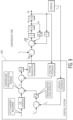
- FIGS. 8-9 are directed to controlling the amount of torque applied to the rotary dancer mechanism 10.
- the controller 40 may also be configured to control the unwind device 16 for controlling the speed at which the web 12 is unwound.
- FIGS. 8-9 illustrate one embodiment of a block diagram for controlling web acceleration. In this manner, the controller 40 may be configured not only to control the speed or acceleration at which the web material 12 is unwound but also control the torque applied to the rotary dancer mechanism 10 in a closed loop fashion.
- the box 200 represents the calculations that occur inside the controller 40.
- the controller 40 calculates a resultant output, T app , which is the amount of torque applied to the rotary dancer mechanism 10 by the rotatable arm 22.
- T app a resultant output
- the circle to the right of the box 200 represents the rotary dancer mechanism 10. Also shown are the forces which act on the rotary dancer mechanism 10.
- the position of the rotary dancer mechanism 10 is monitored by a position sensor 42 and continuously fed to the controller 40 along with web tension monitored by load cells 44, 46 prior to and after the rotary dancer mechanism 10.
- the controller 40 compares the web tension before the rotary dancer mechanism 10 and after the rotary dancer mechanism 10 to determine a web tension value. If the web tension value is out of a specified limit, the controller 40 may then calculate the amount of torque to apply to the rotary dancer mechanism 10. This signal is fed to the motor driving the rotatable arm 22 which adjusts the amount of torque applied to the rotary dancer mechanism 10. As described above, this may be a closed loop system such that these calculations may occur continuously as the web is processed.
- the rotary dancer mechanism of the present disclosure may provide numerous benefits and advantages in relation to conventional linear dancer devices that move up and down. For instance, as shown by the equations above, the product of the mass of a rotary dancer mechanism and gravity are no longer forces that need to be accounted for in adjusting web tension. Consequently, the rotary dancer mechanism is extremely responsive to web tension variations and has a very fast reaction time
- the processing system has the ability to process more significantly OOR rolls while still feeding the unwound web into the processing line under constant tension.
- a manufacturer may not have to dry a web to the same extent as was required in the past.
- a web may be dried to greater than 2 percent moisture by weight, such as from about 2 percent to about 4 percent moisture by weight.
- the rotary dancer mechanism of the present disclosure may allow for stacking of the OOR rolls leading to increased warehouse space and the ability to stockpile greater amounts of material.
Landscapes
- Controlling Rewinding, Feeding, Winding, Or Abnormalities Of Webs (AREA)
Claims (14)
- Verfahren zum Steuern der Spannung in einer Bahn, die von einer unrunden Rolle (14) aus spiralförmig gewickeltem Bahnmaterial (12), eine Hauptkeule (100) und eine Nebenkeule (102) aufweisend, abgewickelt wird, wobei das Verfahren die folgenden Schritte umfasst:a. Bestimmen der Länge der Haupt- und Nebenkeule;b. Bestimmen des effektiven Durchmessers der unrunden Rolle (14);c. Bestimmen des Abstands zwischen der unrunden Rolle und einem rotierenden Tänzermechanismus (10), der eine nicht angetriebene Walze (20) umfasst, die an einem drehbaren Arm (22) mit einer Längsachse (50) angeordnet ist, wobei der drehbare Arm (22) an einem Motor befestigt ist, der so konfiguriert ist, dass er ein gesteuertes Maß an Drehmoment auf den Arm (22) aufbringt und den Arm um 360° dreht;d. Abwickeln von Bahnmaterial von der unrunden Rolle;e. Zuführen von abgewickeltem Bahnmaterial über die nicht angetriebene Walze (20), die an dem drehbaren Arm (22) angeordnet ist;f. Drehen des Arms um 360°;g. Wiederholen der Schritte a)-d), um ein Versatzmaß zu bestimmen; undh. Bewegen der nicht angetriebenen Walze (20) entlang der Längsachse des drehbaren Arms (22) basierend auf dem bestimmten Versatzmaß;wobei der rotierende Tänzermechanismus (10) ferner ein Gegengewicht (48) umfasst, das an dem drehbaren Arm (22) angeordnet und entlang der Längsachse bewegbar ist.
- Verfahren nach Anspruch 1, wobei die Länge der Haupt- und Nebenkeule der unrunden Rolle (14) durch einen Lasersensor gemessen werden.
- Verfahren nach Anspruch 1, ferner umfassend die Schritte des Messens der Spannung der von der Rolle (14) abgewickelten Bahn (12) und des Übermittelns der gemessenen Spannung an eine Steuerung (40), und, basierend auf der gemessenen Spannung, Steuern des Maßes an Drehmoment, das von dem Motor auf den Arm (22) aufgebracht wird;
vorzugsweise wobei die Steuerung (40) einen geschlossenen Regelkreis-Algorithmus zum Bestimmen des Maßes an Drehmoment, das durch den Motor auf den Arm (22) aufgebracht wird, verwendet. - Verfahren zum Steuern der Spannung in einer Bahn (12), die einem Prozess zugeführt wird, umfassend:a. Abwickeln einer Rolle (14) aus spiralförmig gewickeltem Bahnmaterial;b. Zuführen des abgewickelten Bahnmaterials (12) über eine nicht angetriebene Walze (20), die an einem drehbaren Arm (22) mit einer Längsachse (50) angeordnet ist, wobei der drehbare Arm (22) an einem Motor befestigt ist, der so konfiguriert ist, dass er ein gesteuertes Maß an Drehmoment auf den Arm aufbringt;c. Drehen des Arms um 360°;d. Erfassen der Spannung der Bahn (12), nachdem sie die nicht angetriebene Walze (20) verlässt; unde. Steuern der Spannung des Bahnmaterials (12), das die nicht angetriebene Walze (20) verlässt, durch Anpassen der Position der nicht angetriebenen Walze (20) entlang der Längsachse (50) des Arms (22), durch Anpassen des Maßes an Drehmoment, das durch den Motor auf den Arm (22) aufgebracht wird, oder einer Kombination von beiden;wobei die nicht angetriebene Walze (20) gegenüber einem Gegengewicht (48) angeordnet ist und entlang der Längsachse (50) bewegbar ist.
- Verfahren nach Anspruch 1 oder Anspruch 4, ferner umfassend den Schritt des Überwachens der Position des drehbaren Arms (22) und basierend auf den überwachten Positionen, Anpassen des Drehmoments, das durch den Motor auf den Arm (22) aufgebracht wird.
- Verfahren nach Anspruch 1 oder Anspruch 4, ferner umfassend den Schritt des Berechnens eines Maßes an Drehmoment, das durch den Motor auf den Arm aufzubringen ist, unter Verwendung einer Gleichung wie folgt:
 ϕ* eine Winkelposition der unrunden Abwicklungsrolle ist;Θ* eine Winkelposition des rotierenden Tänzermechanismus ist;ψ*ein Winkelphasenversatz der Hauptkeule der Rolle in der unrunden Abwicklungsrolle ist;FPhase ein Winkelphasenversatz der Spannungsspitze in Bezug auf eine Winkelposition der unrunden Abwicklungsrolle ist;Kphase ein Phasenregler ist.
 - Verfahren nach Anspruch 1 oder Anspruch 4, ferner umfassend den Schritt des Berechnens eines Maßes an Drehmoment, das durch den Motor auf den Arm aufzubringen ist, unter Verwendung einer Gleichung wie folgt:
 X* eine Referenz für das Versatzmaß ist;OOR* eine Unrundheitsmessung der Mutterrolle ist;Fmag* eine Referenz für das Maß der Spannungsmesswelligkeit ist;Fmag eine Messung des Maßes der Spannungsmesswelligkeit ist;Kmag ein Größenregler ist.
 - Vorrichtung zum Abwickeln einer Bahn (12), umfassend:eine Rolle (14) aus spiralförmig gewickeltem Bahnmaterial (12);einen ersten Motor zum Drehen der Rolle (14) aus spiralförmig gewickeltem Bahnmaterial; undeinen rotierenden Tänzermechanismus (10) zum Steuern der Spannung von Bahnmaterial, das von der Rolle von spiralförmig gewickeltem Bahnmaterial abgewickelt wird, umfassend einen drehbaren Arm (22) mit einer Längsachse (50) und einem ersten und zweiten Ende, und eine nicht angetriebene Walze (20), die an dem drehbaren Arm (22) angeordnet und entlang der Längsachse (50) bewegbar ist;und einen zweiten Motor, der an dem drehbaren Arm (22) befestigt und so konfiguriert ist, dass er dem Arm ein steuerbares Maß an Drehmoment zuführt;und dadurch gekennzeichnet, dass sie ein Gegengewicht (48) umfasst, das an dem drehbaren Arm (22) gegenüber der nicht angetriebenen Walze (20) angeordnet und entlang der Längsachse (50) bewegbar ist.
- Vorrichtung nach Anspruch 8, wobei der drehbare Arm (22) mit dem zweiten Motor durch eine Welle verbunden ist und um die Welle um 360° drehbar ist.
- Vorrichtung nach Anspruch 8, wobei der zweite Motor durch einen Riemen betriebsmäßig an dem drehbaren Arm (22) befestigt ist.
- Vorrichtung nach Anspruch 8, die ferner eine Wägezelle (44) und eine Steuerung (40) umfasst, wobei die Steuerung (40) mit dem zweiten Motor und der Wägezelle (44) in Kommunikation ist und so konfiguriert ist, dass sie die Spannung des Bahnmaterials, das von der Rolle abgewickelt wird, beim Verlassen des rotierenden Tänzermechanismus (10) erfasst.
- Vorrichtung nach Anspruch 11, wobei die Steuerung (40) konfiguriert ist, das Maß an Drehmoment, das auf den Arm (22) aufgebracht wird, zu steuern.
- Vorrichtung nach Anspruch 11, wobei die Steuerung (40) konfiguriert ist, die Position der nicht angetriebenen Walze (20) entlang der Längsachse (50) des Arms (22) zu steuern.
- Vorrichtung nach Anspruch 11, die ferner einen Positionssensor (42) umfasst, der konfiguriert ist, die Position des drehbaren Arms (22) zu erfassen.
Applications Claiming Priority (2)
| Application Number | Priority Date | Filing Date | Title |
|---|---|---|---|
| US201962799674P | 2019-01-31 | 2019-01-31 | |
| PCT/US2020/016213 WO2020160473A1 (en) | 2019-01-31 | 2020-01-31 | Improved web tension control |
Publications (3)
| Publication Number | Publication Date |
|---|---|
| EP3917865A1 EP3917865A1 (de) | 2021-12-08 |
| EP3917865A4 EP3917865A4 (de) | 2022-11-30 |
| EP3917865B1 true EP3917865B1 (de) | 2025-06-18 |
Family
ID=71840471
Family Applications (1)
| Application Number | Title | Priority Date | Filing Date |
|---|---|---|---|
| EP20748095.5A Active EP3917865B1 (de) | 2019-01-31 | 2020-01-31 | Verbesserte bahnspannungsregelung |
Country Status (6)
| Country | Link |
|---|---|
| US (1) | US11117771B2 (de) |
| EP (1) | EP3917865B1 (de) |
| AU (1) | AU2020216456B2 (de) |
| ES (1) | ES3036876T3 (de) |
| MX (1) | MX2021008547A (de) |
| WO (1) | WO2020160473A1 (de) |
Families Citing this family (16)
| Publication number | Priority date | Publication date | Assignee | Title |
|---|---|---|---|---|
| MX2018004439A (es) | 2015-10-13 | 2018-07-06 | Joa Curt G Inc | Sistemas y metodos de ensamblaje de productos desechables. |
| JP7791651B2 (ja) | 2018-01-29 | 2025-12-24 | カート ジー.ジョア、インコーポレイテッド | 吸収性衛生製品用の弾性複合材構造体を製造する装置および方法 |
| US11891202B2 (en) * | 2018-05-18 | 2024-02-06 | Gea Food Solutions Germany Gmbh | Unwinding a film roll in a packaging machine |
| US11925538B2 (en) | 2019-01-07 | 2024-03-12 | Curt G. Joa, Inc. | Apparatus and method of manufacturing an elastic composite structure for an absorbent sanitary product |
| US12433797B2 (en) | 2019-09-04 | 2025-10-07 | Curt G. Joa, Inc. | Elastic entrapment with waist cap bonding |
| WO2021168473A1 (en) | 2020-02-17 | 2021-08-26 | Curt G. Joa, Inc. | An elastic composite structure for an absorbent sanitary product and an apparatus and method for making said elastic composite structure |
| WO2022235411A1 (en) * | 2021-05-06 | 2022-11-10 | Applied Materials, Inc. | Cross web tension measurement and control |
| US12330894B2 (en) | 2022-04-25 | 2025-06-17 | Curt G. Joa, Inc | System and method for stabilizing web position during splicing of transversely wound material rolls |
| CN115028002A (zh) * | 2022-05-31 | 2022-09-09 | 包头钢铁(集团)有限责任公司 | 一种镀锌机组开卷机卷径计算修正控制方法及系统 |
| US12344492B2 (en) * | 2022-08-29 | 2025-07-01 | Goodrich Corporation | Individual zone tension control |
| IT202200019239A1 (it) * | 2022-09-20 | 2024-03-20 | Comelz Spa | Apparecchiatura per lo svolgimento di rotoli perfezionata |
| US12552627B2 (en) | 2023-05-26 | 2026-02-17 | Bw Converting, Inc. | Model reference adaptive web and winding control |
| CN117438668B (zh) * | 2023-12-21 | 2024-03-29 | 深圳市曼恩斯特科技股份有限公司 | 锂电池卷绕设备的张力控制方法、装置及张力控制模型 |
| CN117509269B (zh) * | 2024-01-03 | 2024-03-22 | 常州凯得新材料科技有限公司 | 一种聚乙烯塑料薄膜生产用张力调节装置 |
| CN118954143A (zh) * | 2024-08-15 | 2024-11-15 | 哈尔滨工业大学(深圳)(哈尔滨工业大学深圳科技创新研究院) | 拉带收卷装置及高精密卷对卷柔性电子印刷装备 |
| CN118637411B (zh) * | 2024-08-16 | 2024-10-25 | 常州市中桓新材料科技有限公司 | Pvc膜生产输送系统及方法 |
Family Cites Families (21)
| Publication number | Priority date | Publication date | Assignee | Title |
|---|---|---|---|---|
| US3659767A (en) | 1969-12-29 | 1972-05-02 | John R Martin | Tension regulation apparatus |
| US3912188A (en) * | 1974-08-26 | 1975-10-14 | Du Pont | Damped flexure mounts for use in web winding |
| US4000865A (en) * | 1975-08-27 | 1977-01-04 | Batson-Cook Company | Controlled tension let-off for unwinding rolls of material |
| US4151594A (en) | 1976-02-26 | 1979-04-24 | Bobst-Champlain, Inc. | Web tension control for high-speed web handling equipment |
| DE2642381C3 (de) * | 1976-09-21 | 1981-01-29 | Maschinenfabrik Goebel Gmbh, 6100 Darmstadt | Einrichtung zum registerhaltigen Zuführen einer Bahn |
| JPS6077058A (ja) * | 1983-10-04 | 1985-05-01 | Toray Ind Inc | シ−ト状物の巻出張力変動低減方法 |
| JP3024859B2 (ja) * | 1992-04-15 | 2000-03-27 | 株式会社西村製作所 | ウエブ材料送り装置 |
| US5659229A (en) | 1995-01-31 | 1997-08-19 | Kimberly-Clark Worldwide, Inc. | Controlling web tension by actively controlling velocity of dancer roll |
| US6473669B2 (en) | 1998-07-03 | 2002-10-29 | Kimberly-Clark Worldwide, Inc. | Controlling web tension, and accumulating lengths of web, by actively controlling velocity and acceleration of a festoon |
| US6856850B2 (en) | 1998-07-03 | 2005-02-15 | Kimberly Clark Worldwide, Inc. | Controlling web tension, and accumulating lengths of web, using a festoon |
| US6845282B2 (en) | 2002-09-04 | 2005-01-18 | The Procter & Gamble Company | Method of controlling tension in a web |
| US8413920B2 (en) | 2003-06-13 | 2013-04-09 | The Procter & Gamble Company | Method and apparatus for unwinding a roll of web material |
| US20040256435A1 (en) | 2003-06-19 | 2004-12-23 | St. Germain Patrick C. | Web tensioning device |
| US6991144B2 (en) | 2004-02-04 | 2006-01-31 | The Procter & Gamble Company | Method of controlling tension in a moving web material |
| US7092781B2 (en) | 2004-12-10 | 2006-08-15 | The Procter & Gamble Company | Method of controlling tension in a web |
| DE102010013782A1 (de) | 2010-04-03 | 2011-10-06 | Robert Bosch Gmbh | Verfahren zur Bestimmung wenigstens eines Reglerparameters eines Tänzerlage-Regelglieds |
| CN102556737B (zh) * | 2011-12-23 | 2014-11-26 | 深圳众为兴技术股份有限公司 | 一种张力控制方法 |
| JP6404018B2 (ja) | 2013-07-16 | 2018-10-10 | 株式会社ジェイテクト | フィラメントワインディング方法及びフィラメントワインディング装置 |
| US10227197B2 (en) | 2013-08-16 | 2019-03-12 | The Procter & Gamble Plaza | Method for reducing the effects of parent roll variations during unwinding |
| US9309081B2 (en) | 2013-10-15 | 2016-04-12 | Kimberly-Clark Worldwide, Inc. | Active center pivot device for controlling sheet tension and method of using same |
| CN108439004A (zh) | 2018-01-29 | 2018-08-24 | 江苏知行科技有限公司 | 一种非晶带材的倒卷设备 |
-
2020
- 2020-01-31 ES ES20748095T patent/ES3036876T3/es active Active
- 2020-01-31 US US16/970,472 patent/US11117771B2/en active Active
- 2020-01-31 EP EP20748095.5A patent/EP3917865B1/de active Active
- 2020-01-31 MX MX2021008547A patent/MX2021008547A/es unknown
- 2020-01-31 WO PCT/US2020/016213 patent/WO2020160473A1/en not_active Ceased
- 2020-01-31 AU AU2020216456A patent/AU2020216456B2/en active Active
Also Published As
| Publication number | Publication date |
|---|---|
| ES3036876T3 (en) | 2025-09-25 |
| EP3917865A4 (de) | 2022-11-30 |
| AU2020216456B2 (en) | 2025-02-06 |
| US20210087011A1 (en) | 2021-03-25 |
| MX2021008547A (es) | 2021-08-19 |
| US11117771B2 (en) | 2021-09-14 |
| WO2020160473A1 (en) | 2020-08-06 |
| AU2020216456A1 (en) | 2021-09-23 |
| EP3917865A1 (de) | 2021-12-08 |
Similar Documents
| Publication | Publication Date | Title |
|---|---|---|
| EP3917865B1 (de) | Verbesserte bahnspannungsregelung | |
| EP3057899B1 (de) | Aktive vorrichtung mit zentralem drehpunkt zur steuerung einer bahnenspannung und verfahren zur verwendung davon | |
| KR101867628B1 (ko) | 권취장치 및 그 제어방법 | |
| FI118594B (fi) | Rullain, jossa on kohotettu puolan kannatuskisko | |
| EP3507221B1 (de) | Bahnwicklungsvorrichtung | |
| US20220106145A1 (en) | Control for Parent Roll Unwinding Apparatus and Methods | |
| PL175079B1 (pl) | Sposób nawijania zwoju materiału na rolkę i urządzenie do nawijania zwoju materiału na rolkę | |
| CA2671379C (en) | Controlled vertical axis unwinding method for rolls of web material | |
| US7028940B2 (en) | Apparatus for unwinding rolls of web material | |
| US7344104B2 (en) | Unwind apparatus | |
| US10526155B2 (en) | Method of controlling operation of a winder for a fiber web | |
| EP1633666B1 (de) | Verfahren und vorrichtung zum abwickeln einer rolle banhmaterials | |
| BR112016007973B1 (pt) | Dispositivo de pivô central ativo para controlar a tensão da folha e método para usar o mesmo | |
| AU2007202217A1 (en) | An apparatus for unwinding rolls of web material | |
| HK1186164A (en) | Winding machine and method for controlling the same |
Legal Events
| Date | Code | Title | Description |
|---|---|---|---|
| STAA | Information on the status of an ep patent application or granted ep patent |
Free format text: STATUS: THE INTERNATIONAL PUBLICATION HAS BEEN MADE |
|
| PUAI | Public reference made under article 153(3) epc to a published international application that has entered the european phase |
Free format text: ORIGINAL CODE: 0009012 |
|
| STAA | Information on the status of an ep patent application or granted ep patent |
Free format text: STATUS: REQUEST FOR EXAMINATION WAS MADE |
|
| 17P | Request for examination filed |
Effective date: 20210817 |
|
| AK | Designated contracting states |
Kind code of ref document: A1 Designated state(s): AL AT BE BG CH CY CZ DE DK EE ES FI FR GB GR HR HU IE IS IT LI LT LU LV MC MK MT NL NO PL PT RO RS SE SI SK SM TR |
|
| DAV | Request for validation of the european patent (deleted) | ||
| DAX | Request for extension of the european patent (deleted) | ||
| A4 | Supplementary search report drawn up and despatched |
Effective date: 20221103 |
|
| RIC1 | Information provided on ipc code assigned before grant |
Ipc: B65H 23/04 20060101ALI20221027BHEP Ipc: B65H 23/188 20060101ALI20221027BHEP Ipc: B65H 59/38 20060101ALI20221027BHEP Ipc: B65H 23/26 20060101AFI20221027BHEP |
|
| GRAP | Despatch of communication of intention to grant a patent |
Free format text: ORIGINAL CODE: EPIDOSNIGR1 |
|
| STAA | Information on the status of an ep patent application or granted ep patent |
Free format text: STATUS: GRANT OF PATENT IS INTENDED |
|
| INTG | Intention to grant announced |
Effective date: 20250121 |
|
| GRAS | Grant fee paid |
Free format text: ORIGINAL CODE: EPIDOSNIGR3 |
|
| GRAA | (expected) grant |
Free format text: ORIGINAL CODE: 0009210 |
|
| STAA | Information on the status of an ep patent application or granted ep patent |
Free format text: STATUS: THE PATENT HAS BEEN GRANTED |
|
| AK | Designated contracting states |
Kind code of ref document: B1 Designated state(s): AL AT BE BG CH CY CZ DE DK EE ES FI FR GB GR HR HU IE IS IT LI LT LU LV MC MK MT NL NO PL PT RO RS SE SI SK SM TR |
|
| RAP3 | Party data changed (applicant data changed or rights of an application transferred) |
Owner name: KIMBERLY-CLARK WORLDWIDE, INC. |
|
| REG | Reference to a national code |
Ref country code: GB Ref legal event code: FG4D |
|
| REG | Reference to a national code |
Ref country code: CH Ref legal event code: EP |
|
| REG | Reference to a national code |
Ref country code: DE Ref legal event code: R096 Ref document number: 602020052933 Country of ref document: DE |
|
| REG | Reference to a national code |
Ref country code: CH Ref legal event code: EP |
|
| REG | Reference to a national code |
Ref country code: IE Ref legal event code: FG4D |
|
| P01 | Opt-out of the competence of the unified patent court (upc) registered |
Free format text: CASE NUMBER: APP_28540/2025 Effective date: 20250616 |
|
| REG | Reference to a national code |
Ref country code: ES Ref legal event code: FG2A Ref document number: 3036876 Country of ref document: ES Kind code of ref document: T3 Effective date: 20250925 |
|
| PG25 | Lapsed in a contracting state [announced via postgrant information from national office to epo] |
Ref country code: FI Free format text: LAPSE BECAUSE OF FAILURE TO SUBMIT A TRANSLATION OF THE DESCRIPTION OR TO PAY THE FEE WITHIN THE PRESCRIBED TIME-LIMIT Effective date: 20250618 |
|
| REG | Reference to a national code |
Ref country code: LT Ref legal event code: MG9D |
|
| PG25 | Lapsed in a contracting state [announced via postgrant information from national office to epo] |
Ref country code: NO Free format text: LAPSE BECAUSE OF FAILURE TO SUBMIT A TRANSLATION OF THE DESCRIPTION OR TO PAY THE FEE WITHIN THE PRESCRIBED TIME-LIMIT Effective date: 20250918 Ref country code: GR Free format text: LAPSE BECAUSE OF FAILURE TO SUBMIT A TRANSLATION OF THE DESCRIPTION OR TO PAY THE FEE WITHIN THE PRESCRIBED TIME-LIMIT Effective date: 20250919 |
|
| PG25 | Lapsed in a contracting state [announced via postgrant information from national office to epo] |
Ref country code: BG Free format text: LAPSE BECAUSE OF FAILURE TO SUBMIT A TRANSLATION OF THE DESCRIPTION OR TO PAY THE FEE WITHIN THE PRESCRIBED TIME-LIMIT Effective date: 20250618 |
|
| PG25 | Lapsed in a contracting state [announced via postgrant information from national office to epo] |
Ref country code: HR Free format text: LAPSE BECAUSE OF FAILURE TO SUBMIT A TRANSLATION OF THE DESCRIPTION OR TO PAY THE FEE WITHIN THE PRESCRIBED TIME-LIMIT Effective date: 20250618 |
|
| PG25 | Lapsed in a contracting state [announced via postgrant information from national office to epo] |
Ref country code: RS Free format text: LAPSE BECAUSE OF FAILURE TO SUBMIT A TRANSLATION OF THE DESCRIPTION OR TO PAY THE FEE WITHIN THE PRESCRIBED TIME-LIMIT Effective date: 20250918 |
|
| REG | Reference to a national code |
Ref country code: NL Ref legal event code: MP Effective date: 20250618 |
|
| PG25 | Lapsed in a contracting state [announced via postgrant information from national office to epo] |
Ref country code: LV Free format text: LAPSE BECAUSE OF FAILURE TO SUBMIT A TRANSLATION OF THE DESCRIPTION OR TO PAY THE FEE WITHIN THE PRESCRIBED TIME-LIMIT Effective date: 20250618 |
|
| PG25 | Lapsed in a contracting state [announced via postgrant information from national office to epo] |
Ref country code: NL Free format text: LAPSE BECAUSE OF FAILURE TO SUBMIT A TRANSLATION OF THE DESCRIPTION OR TO PAY THE FEE WITHIN THE PRESCRIBED TIME-LIMIT Effective date: 20250618 |
|
| PG25 | Lapsed in a contracting state [announced via postgrant information from national office to epo] |
Ref country code: PT Free format text: LAPSE BECAUSE OF FAILURE TO SUBMIT A TRANSLATION OF THE DESCRIPTION OR TO PAY THE FEE WITHIN THE PRESCRIBED TIME-LIMIT Effective date: 20251020 |
|
| REG | Reference to a national code |
Ref country code: AT Ref legal event code: MK05 Ref document number: 1804033 Country of ref document: AT Kind code of ref document: T Effective date: 20250618 |
|
| PG25 | Lapsed in a contracting state [announced via postgrant information from national office to epo] |
Ref country code: IS Free format text: LAPSE BECAUSE OF FAILURE TO SUBMIT A TRANSLATION OF THE DESCRIPTION OR TO PAY THE FEE WITHIN THE PRESCRIBED TIME-LIMIT Effective date: 20251018 |
|
| PG25 | Lapsed in a contracting state [announced via postgrant information from national office to epo] |
Ref country code: AT Free format text: LAPSE BECAUSE OF FAILURE TO SUBMIT A TRANSLATION OF THE DESCRIPTION OR TO PAY THE FEE WITHIN THE PRESCRIBED TIME-LIMIT Effective date: 20250618 Ref country code: SM Free format text: LAPSE BECAUSE OF FAILURE TO SUBMIT A TRANSLATION OF THE DESCRIPTION OR TO PAY THE FEE WITHIN THE PRESCRIBED TIME-LIMIT Effective date: 20250618 |
|
| PG25 | Lapsed in a contracting state [announced via postgrant information from national office to epo] |
Ref country code: CZ Free format text: LAPSE BECAUSE OF FAILURE TO SUBMIT A TRANSLATION OF THE DESCRIPTION OR TO PAY THE FEE WITHIN THE PRESCRIBED TIME-LIMIT Effective date: 20250618 |
|
| PG25 | Lapsed in a contracting state [announced via postgrant information from national office to epo] |
Ref country code: PL Free format text: LAPSE BECAUSE OF FAILURE TO SUBMIT A TRANSLATION OF THE DESCRIPTION OR TO PAY THE FEE WITHIN THE PRESCRIBED TIME-LIMIT Effective date: 20250618 |
|
| PG25 | Lapsed in a contracting state [announced via postgrant information from national office to epo] |
Ref country code: EE Free format text: LAPSE BECAUSE OF FAILURE TO SUBMIT A TRANSLATION OF THE DESCRIPTION OR TO PAY THE FEE WITHIN THE PRESCRIBED TIME-LIMIT Effective date: 20250618 |
|
| PG25 | Lapsed in a contracting state [announced via postgrant information from national office to epo] |
Ref country code: RO Free format text: LAPSE BECAUSE OF FAILURE TO SUBMIT A TRANSLATION OF THE DESCRIPTION OR TO PAY THE FEE WITHIN THE PRESCRIBED TIME-LIMIT Effective date: 20250618 Ref country code: SK Free format text: LAPSE BECAUSE OF FAILURE TO SUBMIT A TRANSLATION OF THE DESCRIPTION OR TO PAY THE FEE WITHIN THE PRESCRIBED TIME-LIMIT Effective date: 20250618 |
|
| PGFP | Annual fee paid to national office [announced via postgrant information from national office to epo] |
Ref country code: ES Payment date: 20260202 Year of fee payment: 7 |
|
| PG25 | Lapsed in a contracting state [announced via postgrant information from national office to epo] |
Ref country code: DK Free format text: LAPSE BECAUSE OF FAILURE TO SUBMIT A TRANSLATION OF THE DESCRIPTION OR TO PAY THE FEE WITHIN THE PRESCRIBED TIME-LIMIT Effective date: 20250618 |
|
| PGFP | Annual fee paid to national office [announced via postgrant information from national office to epo] |
Ref country code: IT Payment date: 20260121 Year of fee payment: 7 |
|
| PLBE | No opposition filed within time limit |
Free format text: ORIGINAL CODE: 0009261 |
|
| STAA | Information on the status of an ep patent application or granted ep patent |
Free format text: STATUS: NO OPPOSITION FILED WITHIN TIME LIMIT |