EP3918143B1 - Procede de demontage d'un aérateur, un aérateur et ensemble d'un aérateur et d'un outil - Google Patents
Procede de demontage d'un aérateur, un aérateur et ensemble d'un aérateur et d'un outil Download PDFInfo
- Publication number
- EP3918143B1 EP3918143B1 EP19832855.1A EP19832855A EP3918143B1 EP 3918143 B1 EP3918143 B1 EP 3918143B1 EP 19832855 A EP19832855 A EP 19832855A EP 3918143 B1 EP3918143 B1 EP 3918143B1
- Authority
- EP
- European Patent Office
- Prior art keywords
- housing
- jet
- jet aerator
- jet regulator
- tool
- Prior art date
- Legal status (The legal status is an assumption and is not a legal conclusion. Google has not performed a legal analysis and makes no representation as to the accuracy of the status listed.)
- Active
Links
Images


Classifications
-
- E—FIXED CONSTRUCTIONS
- E03—WATER SUPPLY; SEWERAGE
- E03C—DOMESTIC PLUMBING INSTALLATIONS FOR FRESH WATER OR WASTE WATER; SINKS
- E03C1/00—Domestic plumbing installations for fresh water or waste water; Sinks
- E03C1/02—Plumbing installations for fresh water
- E03C1/08—Jet regulators or jet guides, e.g. anti-splash devices
- E03C1/084—Jet regulators with aerating means
-
- E—FIXED CONSTRUCTIONS
- E03—WATER SUPPLY; SEWERAGE
- E03C—DOMESTIC PLUMBING INSTALLATIONS FOR FRESH WATER OR WASTE WATER; SINKS
- E03C1/00—Domestic plumbing installations for fresh water or waste water; Sinks
- E03C1/02—Plumbing installations for fresh water
- E03C1/08—Jet regulators or jet guides, e.g. anti-splash devices
- E03C1/086—Jet regulators or jet guides, easily mountable on the outlet of taps
Definitions
- the invention relates to a method for removing a jet regulator from a faucet outlet, wherein the jet regulator has a housing and a locking element movably arranged on the housing, wherein the locking element is acted upon by a spring element accessible from outside the faucet outlet and, in its rest position, protrudes beyond the housing in order to hold the jet regulator in the faucet outlet, wherein a tool for removal is inserted into the faucet outlet in an insertion direction.
- the invention also relates to a jet regulator, wherein the jet regulator has a housing and a locking element arranged movably on the housing, wherein the locking element is acted upon by a spring element accessible from outside the fitting outlet and protrudes beyond the housing in its rest position in order to hold the jet regulator in the fitting outlet, wherein a tool for removal is inserted into the fitting outlet in an insertion direction.
- the locking element can be disengaged.
- the aerator of the type mentioned above is not held in place in a fitting by means of a threaded connection between an outlet nozzle and the fitting outlet, but is usually fixed to the fitting exclusively by means of a locking mechanism formed by the locking and spring element.
- a The outlet nozzle can be omitted, which creates a more aesthetic overall impression.
- the jet regulators mentioned above can be rectangular jet regulators (rectangular jet regulators).
- the invention relates to a set consisting of a jet regulator and a tool.
- Locking elements of known types therefore usually lead to axial fixation by supporting them on an impact surface of the fitting outlet that runs transversely or perpendicularly to the direction of insertion.
- This also has the disadvantage that a buffer space must be provided in the fitting outlet in order to be able to lift the locking element from the impact surface in the direction of insertion and then move it towards the housing.
- dirt occurs in the buffer space after prolonged use of the jet regulator, it is often extremely difficult to remove.
- a jet regulator is known, which can be inserted with its jet regulator housing from the outlet front into the water outlet of a sanitary outlet fitting and can be releasably secured or fixed in the water outlet position when in use.
- a known jet regulator has a jet regulator housing that is inserted into the watercourse of a sanitary outlet fitting and is detachably fixed, the jet regulator housing having a wall section that delimits a housing space that is open towards the outlet front on the inside and that has at least one retaining projection on the outside, this retaining projection being able to be raised into a holding position against the restoring force caused by the inherent elasticity of the wall material or being able to be molded into the housing space from a holding position.
- a safety slide is also provided that can be moved from the outlet front into the housing space in such a way that the sliding movement of the safety slide can be converted into a lifting movement of the wall section that has the at least one retaining projection and/or molding of this wall section can be prevented by pushing the safety slide into the housing space.
- a perlator for fittings, particularly for faucets, is known.
- This perlator is held by a threaded sleeve that can be screwed onto the threaded outlet end of the fitting.
- This perlator is further characterized in that the perlator can be replaced from below in the direction of flow without unscrewing the sleeve.
- the invention is based on the object of providing a method and a jet regulator of the type mentioned at the outset, wherein the problems mentioned are to be eliminated by improving the usage properties.
- a method of the type mentioned at the outset is first proposed, in which the spring element is loaded with the tool during insertion until the locking element releases the jet regulator.
- a new type of unlocking mechanism is thus formed in order to be able to release a jet regulator held in a faucet outlet more easily.
- the locking element is guided by a guide formed by the housing and/or the locking element and/or the spring element is/are formed separately from the housing.
- the tool engages in an undercut on the jet regulator oriented in the direction of insertion in order to be able to pull the jet regulator out of the fitting outlet.
- a force can be transmitted to the jet regulator by means of the tool.
- the tool can have at least one projection, preferably at least two projections, which engage in the undercut(s) on the jet regulator in the position of use. In this way, a pulling mechanism can be formed.
- the invention This is the first time that a release mechanism has been decoupled from a pull mechanism. This makes it much easier to pull the jet regulator out of the faucet outlet.
- the at least one undercut can protrude into a gap-forming recess on the housing of the jet regulator provided for inserting the tool.
- the undercut can protrude from the housing transversely or perpendicularly to the insertion direction.
- the at least one projection can have a contact surface inclined in the direction of the jet regulator, which acts on the at least one undercut during insertion, so that the projection is deflected before it snaps into place after the undercut in the insertion direction.
- the at least one projection can be arranged, for example, on a spring means of the tool.
- the undercut itself can have a corresponding counter-contact surface, preferably aligned parallel to the contact surface of the projection, in order to be able to displace the counter-contact surface on the contact surface when the tool is inserted.
- a jet regulator of the type mentioned at the outset is proposed to solve the problem, wherein the spring element is designed and/or arranged such that it can be acted upon by a tool inserted into the fitting outlet in an insertion direction until the locking element releases the jet regulator.
- the locking element is guided by a guide formed by the housing is guided. and/or that the locking element and/or the spring element is/are formed separately from the housing.
- the spring element can, for example, be arranged in a recess, for example the recess already mentioned above, on the housing which is provided for inserting the tool.
- the spring element does not protrude beyond the housing in the rest position.
- the spring element can have at least two legs connected to one another, in particular connected to one another at an apex.
- the two legs are moved towards one another or away from one another until the locking element or the locking elements connected to one leg no longer protrude beyond the housing.
- the two legs are preferably moved towards one another by the tool in a direction transverse or perpendicular to the insertion direction in order to move the locking element or the locking elements from the rest position into the release position. The tool thus presses the two legs of the spring element together, for example, in order to be able to remove the jet regulator.
- the spring element is connected to the locking element or elements, whereby the locking element or elements are moved when the spring element is adjusted.
- the locking element or locking elements of the jet regulator protrude beyond the housing in the rest position in a direction that is diagonal or perpendicular to the direction of insertion.
- at least one locking element forms a radial locking mechanism on the faucet outlet.
- the holding force exerted by the locking element (can correspond to the tension force of the spring element) acts perpendicularly or almost perpendicularly on the inner wall of the faucet outlet.
- a jet regulator according to the invention can also have an outlet structure that has slats, the slats being positioned outwards at least in one area of the outlet structure in order to generate a diverging water flow.
- This makes it possible to produce a particularly attractive outlet pattern.
- an almost rectangular water jet can thus be generated, for example with a rectangular jet former.
- the aforementioned region is arranged in an edge region of the outlet structure and/or that the region is arranged in a central region of the outlet structure.
- the outwardly positioned slats have a cross-section oriented transversely to their extension, which has a curved outer contour. This has the advantage that a particularly good separation of individual water jets is possible, whereby a better jet shape can be achieved. For example, a better rectangular jet shape can be achieved in this way if the jet regulator is rectangular.
- lamellae can be arranged with a cross-section oriented transversely to their extension, which has a direction of flow outer contour. These lamellae can therefore extend in the direction of flow. In particular, these lamellae outside the previously mentioned area are straight and lead to a straight-line flowing water jet.
- the jet regulator as previously described and claimed herein, also has a jet acceleration unit which has a seal on the outside that runs around a flow direction, and on the outflow side of which jet shaping elements, in particular lamellae, are arranged that extend transversely to the flow direction, wherein the jet shaping elements each have a free end with which they protrude from a support wall running along the flow direction.
- a jet acceleration unit which has a seal on the outside that runs around a flow direction, and on the outflow side of which jet shaping elements, in particular lamellae, are arranged that extend transversely to the flow direction, wherein the jet shaping elements each have a free end with which they protrude from a support wall running along the flow direction.
- the jet acceleration unit is formed at an inflow end of a jet ventilation area.
- the jet acceleration unit can be formed as a perforated plate or as a diffuser-diffuser ring combination.
- the jet shaping elements can also have an elongated, non-circular outer contour transverse to the flow direction.
- the free ends of the jet shaping elements can be arranged on a long side of the outer contour in the position of use.
- the support wall can be arranged on a long side of the outer contour in the position of use.
- the free ends can form a laterally open area in a peripheral wall.
- the jet-forming elements can end at a uniform height.
- the locking element is guided according to the invention in a guide formed by the housing.
- the guide can be designed as a sliding bearing and/or the guide can determine that the locking element can be adjusted in one, in particular only one, degree of freedom, preferably in a straight line.
- At least one stop is formed on the housing, which is acted upon by a corresponding counter-stop on the locking element in a locking position.
- the stop can define how far the locking element protrudes from the housing at most. The stop and counter-stop are therefore spaced apart from one another in a release position and/or contact one another in a locking position.
- the locking element and/or the spring element can be designed separately from the housing.
- the locking element and/or the spring element is/are not designed as part of the housing, but separately from it.
- the jet regulator can have two locking elements, each of which is connected to the spring element or to a spring element.
- a locking lug can be formed on a free end of the locking element, which is retracted into a release position when the spring element is actuated.
- the locking element can also be or the locking elements are adjusted.
- the locking element and/or the spring element are therefore not molded onto the housing and can therefore be adjusted relative to the housing.
- the separate design of the locking element and/or the spring element from the housing has the advantage that the locking lugs at the ends of the locking elements can be adjusted simultaneously. When the spring element or spring elements are actuated, the locking lugs are released simultaneously.
- the locking lugs can also be adjusted simultaneously even though they protrude from the housing on opposite sides of the jet regulator. In other words, they are far apart from each other on opposite sides of the jet regulator. This allows the jet regulator to be particularly well fixed in place when inserted, and release is also made easier by simply applying pressure to the central spring element.
- This design means that the spring element is not applied at the locking point, but at a distance from it. This means that no space is required to insert the tool at the locking point.
- a jet regulator holder of a fitting can be used to close off a laterally open area of a jet regulator, as described and claimed herein, wherein the laterally open area is then provided by the free ends of the jet shaping elements and the jet regulator holder covers the laterally open area of the jet regulator inserted into the jet regulator holder.
- the invention relates to a set comprising a jet regulator, as described and claimed herein, and a tool for carrying out a Method as described and claimed herein. The invention will now be described in more detail using embodiments, but is not limited to these embodiments. Further examples of how the invention can be carried out are provided by the combination of the subclaims.
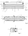
- the jet regulator 1 is designed to be inserted into a jet regulator holder 25 provided for this purpose on a faucet outlet 2 in the position of use and to be fixed therein.
- the jet regulator 1 has a special outlet structure 9.
- the outlet structure 9 comprises a plurality of steel form elements 17 arranged at a distance from one another.
- the jet shaping elements 17 comprise slats 10 which are arranged next to each other are arranged in at least one row on an outlet side of the jet regulator 1.
- the lamellae 10 form an outlet pattern of the total jet of a fluid flowing through. Since they are arranged in the flow path of the jet regulator 1, they are washed around by the total jet.
- the outlet structure 9 comprises an area 11 in which the slats 10 are positioned outwards in order to generate a diverging water flow.
- the slats can be bent outwards and/or arranged at an angle compared to the flow direction 18.
- the said area 11 is formed in the edge areas 12.
- the slats 10 in the aforementioned area 11 have, for example, a cross-section 14 with a curved outer contour. They therefore deflect the fluid flow.
- the lamellae 10 in the central region 13, however, are straight and form a straight fluid flow. This means that the lamellae 10 arranged outside the region 11 have a cross-section that has an outer contour aligned in the direction of flow. Furthermore, the two outermost lamellae 10 in the row of lamellae 10 are also straight.
- the slats 10 extend perpendicularly or transversely to the flow direction 18.
- the steel shaped elements 17 are formed on a support wall 20 of the housing 3.
- the jet shaping elements 17 and the housing 3 are thus one piece.
- the steel shaped elements 17, in particular the slats 10, have a free end 19, via which they are not arranged on a support wall 20, but lie freely.
- the free ends 19 of the steel shaped elements 17 and the support wall 20 each form a long side of the outer contour 23 of the jet regulator 1.
- the steel shaped elements 17, in particular the slats 10 protrude transversely or vertically from the support wall 20 into the flow path.
- a peripheral wall of the housing 3 has a region 24 that is in particular laterally open.
- the jet-forming elements 17 have a uniform length or at least a large part of the jet-forming elements 17 have a uniform length. They therefore end at a uniform height.
- a jet acceleration unit 15 is arranged upstream of the outlet structure 9 in the flow protection 18.
- the jet acceleration unit 15 is in turn arranged upstream of a jet ventilation area 21 in the flow direction 18.
- a liquid flowing through the jet regulator 1 thus first flows through the passage openings of the jet acceleration unit 15, then through the jet aeration area 21, in which the liquid is mixed with air before the jet is formed in the outlet structure 9 and leaves the jet regulator or the fitting outlet 2 on the outlet side.
- the jet aeration area 21 is formed within the housing 3 in the flow path of the liquid.
- several jet shaping elements 17 are arranged, which as shown in the Figures 1 to 7 shown, for example, can be designed as distributor elements 36 in order to be able to break up the water jet and to mix it better with air sucked in from the outside through at least one air channel 37.
- At least one air channel 37 is formed on the housing 3, which breaks through at least one wall of the housing 3 in order to be able to suck air from the outside into the jet ventilation area 21 by means of the negative pressure created here.
- the at least one air channel 37 is formed after the seal 16 in the flow direction 18. Further preferably, the at least one air channel 37 can be arranged on a narrow side of the housing 3.
- the air channel 37 is formed at least partially by a boundary wall 39 extending in the flow direction 18, which laterally limits the flow path.
- the boundary wall 39 extends in the flow direction 18 over the entire area in which the jet ventilation area 21 and/or the outlet structure 9 is/are arranged.
- the air channel 39 can therefore run between an outer wall of the housing 3 and the boundary wall 39.
- An outer end of the air channel 39 can be located, for example, on the outlet side of the jet regulator 1.
- the jet regulator 1 has at least two air channels 37.
- these can be formed on opposite sides, for example narrow sides of the housing 3.
- the distributor elements 36 can - similar to the previously described slats 10 - be formed in one piece with the housing 3.
- a cross-section of the distributor elements 36 can, for example, have rounded corners, in particular be round. The rounded corners make it easier to avoid noise. However, other shapes are also possible.
- the decisive factor here is that the distributor elements 36 represent a flow obstacle within the flow path, which can be achieved, for example, by the distributor elements 36 having an impact surface that runs at least partially transverse to the flow direction 18.
- the distributor elements 36 of the embodiment shown are in two rows, each arranged next to one another, wherein the distributor elements 36 of the first and second rows are arranged offset from one another in order to achieve the best possible division of a fluid flow and mixing with air.
- the distributor elements 36 are formed on one or the already mentioned support wall 20 of the housing 3 and protrude, in particular transversely or vertically, into the flow path. Furthermore, the distributor elements 36 each have free ends 19, which form the open area 24 in the peripheral wall of the housing 3, in particular together with the lamellae 10. As shown in the Figures 1 to 7 As shown, the distributor elements 36 have a uniform height with the slats 10. The slats 10 are arranged downstream of the distributor elements 36.
- the laterally open region 24 extends over at least 10%, in particular at least 20%, in particular at least 25%, in particular at least 33%, in particular at least 50%, preferably at least 60%, preferably at least 65%, preferably at least 80%, preferably at least 90%, of one side of the jet regulator 1, in particular the long side of the jet regulator 1.
- the jet regulator 1 has a circumferential seal 16 on the outside of the jet acceleration unit 15. By means of the seal 16, it is possible to seal an external transition from the jet acceleration unit 15 to the downstream outlet structure 9 in the position of use by the seal 16 resting on the inside of the fitting outlet 2.
- the jet regulator holder 25 of the faucet outlet 2 has a stepped structure. This has the advantage that the seal 16 is not pushed over the entire length of the jet regulator holder 25 with friction when installing and removing the jet regulator 1. must be inserted. When inserted, the seal is pressed against the wall of the faucet outlet 2 and compressed. It can be provided that the jet regulator holder 25 has a groove into which the seal 16 is inserted when inserted, whereby the seal 16 does not completely fill the groove in order to enable better sealing.
- the jet acceleration unit 15 can be designed, for example, as a perforated plate 26 and/or as a diffuser-diffuser ring combination (not shown).
- the diffuser-diffuser ring combination can, in a manner known per se, have a diffuser acting as an impact plate, followed by an annular nozzle delimited by a rectangular diffuser ring.
- the jet regulator holder 25 covers the laterally open area 24.
- the open area 24 is thus covered by an inner wall of the jet regulator holder 25.
- the cover does not result in complete sealing, but a clearance is provided to allow for certain tolerances.
- the outlet structure 9 made of jet shaping elements 17 - such as slats 10 and distributor elements 36 - can be formed as a part molded onto the housing 3, in particular monolithically connected to the housing 3. For example, it can be manufactured using an injection molding process.
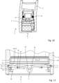
- a further embodiment of a jet regulator 1 is shown as a set with a tool 6.
- the jet regulator 1 has a movable guided locking element 4, which can be acted upon by a spring element 5 accessible from outside the fitting outlet 2 and/or wherein a force transmission from the spring element 5 to the locking element 4 is possible.
- the locking element 4 is connected to the spring element.
- the locking element 4 and the spring element 5 can be formed in one piece, in particular monolithically.
- the locking element 4 protrudes beyond an outer side of a wall of the housing 3.
- the rest position corresponds to the locking position in which the jet regulator 1 is held in the fitting outlet 2.
- the spring element 5 has two legs 34, which are connected to one another in particular at a vertex.
- the two legs 34 spread out in two opposite directions, in particular in the rest position, so that an angle is enclosed between the two legs 34.
- a force transmission from the spring element 5 to a locking element 4 is possible via the two remote ends of the two legs 34 of the spring element 5, since the remote ends are each connected to a locking element 4 and/or act on it.
- the locking elements 4 are connected to the spring element 5 at the remote ends of the spring element 5.
- the locking element 4 and the spring element 5 thus create a new type of unlocking mechanism 29.
- a force in particular a clamping force generated by the spring element 5, acts in a radial direction and/or vertically or almost vertically on an inner wall of the fitting outlet 2 through the locking element 4.
- a special tool 6 is required to enable unlocking. To do this, the tool 6 must be inserted into the fitting outlet 2 in an insertion direction 7, whereby it thereby acts on the spring element 5 arranged outside the housing 3 during insertion until the locking element 4 releases the jet regulator 1.
- the tool 6 shown has two rigid arms 35 which protrude from a base body 40 designed as a handle part.
- the rigid arms 35 have a distance between them which is smaller than a distance between the two remote ends of the legs 34.
- the insertion direction 7 can run along or parallel to a longitudinal axis and/or a central axis of the jet regulator 1.
- the two legs 34 are pressed together so that the distance between the spread ends of the two legs 34 is reduced.
- the locking elements 4, which protrude beyond the housing 3 in the rest position, are thereby retracted so that the locking is released.
- the at least one locking element 4 is retracted in a direction running perpendicularly or transversely to the insertion direction 7, in particular in a straight line.
- the at least one locking element 4 is supported by a guide 41 formed on the housing 3, which can be designed, for example, as a plain bearing 38. Furthermore, locking elements 4 and spring element 5 are held on the housing 3 by the guide 41, in particular by the plain bearing 38.
- the locking element 4 is adjustable in one degree of freedom by the guide 41, preferably adjustable in a straight line.
- the tool 6 has at least one projection 30, in particular two projections 30, which protrude/protrude from a spring means 33 transversely to the insertion direction 7.
- a contact surface 31 aligned obliquely to the insertion direction 7 is formed.
- the tool 6 is flat so that it can be inserted in particular on the back of the jet regulator 1.
- the spring elements 33 therefore do not have to be released from undercuts or locking lugs 44 when removing them.
- an undercut 8 is formed which is oriented in the insertion direction 7 and which protrudes transversely or perpendicularly to the insertion direction 7.
- the undercut further has a counter-contact surface 32 aligned obliquely to the insertion direction 7 and/or at least almost parallel to the contact surface 31 of the projection 30.
- a pulling mechanism 28 is formed which is decoupled from the previously described unlocking mechanism 29.
- decoupling the jet regulator 1 from the fitting outlet 2 and coupling the jet regulator 1 to the tool 6 is only possible by inserting the tool 6, in particular exclusively in the insertion direction 7 into the fitting outlet 2.
- the jet regulator 1 can have a locking element 4 or several locking elements 4, which are connected to a spring element 5 or each to a spring element 5. However, it is advantageous if several locking elements 4 are connected to a common spring element 5 or if the locking elements 4 are each connected to a spring element 5 and the two spring elements 5 are in turn connected to one another.
- the locking element 4 and/or the spring element 5 are designed separately from the housing 3 in the embodiment variant of the jet regulator 1 shown.
- the locking element 4 and/or the spring element 5 is/are not designed as part of the housing 3, but separately from it.
- the jet regulator 1 can preferably have two locking elements 4, each of which is connected to the spring element 5 or to a spring element 5.
- a locking lug 44 is formed on the free ends of the locking elements 4, which are simultaneously retracted into a release position when the spring element 5 is actuated. By centrally actuating the The locking element 4 or the locking elements 4 can therefore also be adjusted using the spring element 5.
- the locking element 4 and/or the spring element 5 are therefore not formed on the housing 3 and can therefore be adjusted relative to the housing 3.
- the separate design of the locking element 4 and/or the spring element 5 from the housing 3 has the advantage that the locking lugs 44 at the ends of the locking elements 4 can be adjusted simultaneously. When the spring element 5 or the spring elements 5 are actuated, the locking lugs 44 are thus released simultaneously. The simultaneous adjustment of the locking lugs 44 is also possible, although they protrude from the housing 3 on opposite sides of the jet regulator 1. Release is achieved by simply applying pressure to the central spring element 5. This design means that the spring element 5 is not applied at the locking location, but at a distance from it. This means that no space is required to insert the tool at the locking location.
- the invention also relates to a method according to claim 1 for removing a jet regulator 1 from a fitting outlet 2, a jet regulator 1 and a set of a jet regulator 1 and a tool 6, wherein the jet regulator 1 has a housing 3 and a locking element 4 movably mounted on the housing 3, wherein the locking element 4 is adjustable by means of a force transmission from a spring element 5 arranged within a recess of the housing 3 and accessible from outside the fitting outlet 2 to the locking element 4, wherein the locking element 4 protrudes beyond the housing 3 in its rest position in order to hold the jet regulator 1 in the fitting outlet 2, wherein a tool 6 for removal is inserted in an insertion direction 7 into the fitting outlet 2, wherein the spring element 5 is acted upon by the tool 6 during insertion until the locking element 4 holds the jet regulator 1 releases.
Landscapes
- Health & Medical Sciences (AREA)
- Life Sciences & Earth Sciences (AREA)
- Engineering & Computer Science (AREA)
- Hydrology & Water Resources (AREA)
- Public Health (AREA)
- Water Supply & Treatment (AREA)
- Nozzles (AREA)
- Jet Pumps And Other Pumps (AREA)
- Domestic Plumbing Installations (AREA)
- Cleaning In General (AREA)
Claims (6)
- Procédé pour le démontage d'un aérateur (1) d'une sortie de robinetterie (2), dans lequel l'aérateur (1) comporte un corps (3) et un élément d'enclenchement (4) disposé de façon mobile sur le corps (3),dans lequel l'élément d'enclenchement (4) est soumis à l'action d'un élément de ressort (5) qui est accessible par l'extérieur de la sortie de robinetterie (2) quand l'aérateur (1) est inséré dans la sortie de robinetterie (2) dans la position d'utilisation, etdans lequel l'élément d'enclenchement (4) dépasse au-delà du corps (3) dans la position d'utilisation pour retenir l'aérateur (1) dans la sortie de robinetterie (2),dans lequel un outil (6) est inséré dans un sens d'insertion (7) dans la sortie de robinetterie (2) en vue du retrait et dans lequel l'élément de ressort (5) est soumis à l'action de l'outil (6) lors de l'insertion jusqu'à ce que l'élément d'enclenchement (4) libère l'aérateur (1),dans lequel l'élément d'enclenchement (4) est guidé par un guide (41) formé par le corps (3) et/ou l'élément d'enclenchement (4) et/ou l'élément de ressort (5) sont formés séparément du corps (3).
- Procédé selon la revendication 1, dans lequel l'outil (6) s'enclenche dans une contre-dépouille (8) de l'aérateur (1) orientée dans le sens de l'insertion (7) pour pouvoir retirer l'aérateur (1) de la sortie de robinetterie (2).
- Aérateur (1) à insérer dans une sortie de robinetterie (2), en particulier pour la mise en oeuvre d'un procédé selon l'une des revendications 1 à 2,dans lequel l'aérateur (1) comporte un corps (3) et un élément d'enclenchement (4) disposé de façon mobile sur le corps (3),dans lequel l'élément d'enclenchement (4) est soumis à l'action d'un élément de ressort (5) qui est accessible par l'extérieur de la sortie de robinetterie (2) quand l'aérateur (1) est inséré dans la sortie de robinetterie (2) dans la position d'utilisation, etdans lequel l'élément d'enclenchement (4) dépasse au-delà du corps (3) dans la position d'utilisation ou dans sa position de repos pour retenir l'aérateur (1) dans la sortie de robinetterie (2),et dans lequel l'élément de ressort (5) est conformé et/ou disposé de telle manière qu'il puisse être soumis à l'action d'un outil (6) inséré dans un sens d'insertion (7) dans la sortie de robinetterie (2) jusqu'à ce que l'élément d'enclenchement (4) libère l'aérateur (1),l'élément d'enclenchement (4) étant guidé par un guide (41) formé par le corps (3) et/ou l'élément d'enclenchement (4) et/ou l'élément de ressort (5) étant formés séparément du corps (3).
- Aérateur (1) selon l'une des revendications précédentes concernant un aérateur, dans lequel le guide (41) est conformé comme un palier lisse (38) et/ou
dans lequel l'élément d'enclenchement (4) peut être déplacé par le guide (41) sur un degré de liberté, de préférence en ligne droite. - Aérateur (1) selon l'une des revendications précédentes concernant un aérateur, dans lequel est en outre prévue sur le corps (3) au moins une butée (42) qui est amenée dans une position d'enclenchement par l'action d'une contre-butée correspondante (43) sur l'élément d'enclenchement (4), en particulier dans lequel la butée (42) définit de combien l'élément d'enclenchement (4) dépasse au maximum du corps (3).
- Ensemble composé d'un aérateur (1) selon l'une des revendications 3 à 5 et d'un outil (6), dans lequel l'élément de ressort (5) est conformé et disposé de telle sorte que, dans la position d'utilisation, l'élément de ressort (5) puisse être soumis à l'action de l'outil (6) lors de l'insertion de l'outil (6) dans la sortie de robinetterie (2) jusqu'à ce que l'élément d'enclenchement (4) libère l'aérateur (1), de sorte que l'aérateur (1) peut ensuite être retiré de la sortie de robinetterie (2).
Priority Applications (3)
| Application Number | Priority Date | Filing Date | Title |
|---|---|---|---|
| EP26155586.6A EP4711536A2 (fr) | 2019-02-01 | 2019-12-13 | Procédé pour retirer un régulateur de jet d'une sortie de robinet, régulateur de jet, utilisation d'un récepteur de régulateur de jet et ensemble d'un régulateur de jet et d'un outil |
| EP22194953.0A EP4187031A1 (fr) | 2019-02-01 | 2019-12-13 | Régulateur de jet |
| EP22194943.1A EP4202134B1 (fr) | 2019-02-01 | 2019-12-13 | Un régulateur de jet |
Applications Claiming Priority (2)
| Application Number | Priority Date | Filing Date | Title |
|---|---|---|---|
| DE202019100611.0U DE202019100611U1 (de) | 2019-02-01 | 2019-02-01 | Strahlregler und Satz aus einem Strahlregler und einem Werkzeug |
| PCT/EP2019/085017 WO2020156726A1 (fr) | 2019-02-01 | 2019-12-13 | Procédé pour enlever un régulateur de jet d'une robinetterie de distribution sanitaire, régulateur de jet, utilisation d'un logement de régulateur de jet et jeu constitué d'un régulateur de jet et d'un outil |
Related Child Applications (5)
| Application Number | Title | Priority Date | Filing Date |
|---|---|---|---|
| EP26155586.6A Division EP4711536A2 (fr) | 2019-02-01 | 2019-12-13 | Procédé pour retirer un régulateur de jet d'une sortie de robinet, régulateur de jet, utilisation d'un récepteur de régulateur de jet et ensemble d'un régulateur de jet et d'un outil |
| EP22194943.1A Division-Into EP4202134B1 (fr) | 2019-02-01 | 2019-12-13 | Un régulateur de jet |
| EP22194943.1A Division EP4202134B1 (fr) | 2019-02-01 | 2019-12-13 | Un régulateur de jet |
| EP22194953.0A Division-Into EP4187031A1 (fr) | 2019-02-01 | 2019-12-13 | Régulateur de jet |
| EP22194953.0A Division EP4187031A1 (fr) | 2019-02-01 | 2019-12-13 | Régulateur de jet |
Publications (3)
| Publication Number | Publication Date |
|---|---|
| EP3918143A1 EP3918143A1 (fr) | 2021-12-08 |
| EP3918143C0 EP3918143C0 (fr) | 2025-01-15 |
| EP3918143B1 true EP3918143B1 (fr) | 2025-01-15 |
Family
ID=69147588
Family Applications (4)
| Application Number | Title | Priority Date | Filing Date |
|---|---|---|---|
| EP19832855.1A Active EP3918143B1 (fr) | 2019-02-01 | 2019-12-13 | Procede de demontage d'un aérateur, un aérateur et ensemble d'un aérateur et d'un outil |
| EP22194953.0A Pending EP4187031A1 (fr) | 2019-02-01 | 2019-12-13 | Régulateur de jet |
| EP22194943.1A Active EP4202134B1 (fr) | 2019-02-01 | 2019-12-13 | Un régulateur de jet |
| EP26155586.6A Pending EP4711536A2 (fr) | 2019-02-01 | 2019-12-13 | Procédé pour retirer un régulateur de jet d'une sortie de robinet, régulateur de jet, utilisation d'un récepteur de régulateur de jet et ensemble d'un régulateur de jet et d'un outil |
Family Applications After (3)
| Application Number | Title | Priority Date | Filing Date |
|---|---|---|---|
| EP22194953.0A Pending EP4187031A1 (fr) | 2019-02-01 | 2019-12-13 | Régulateur de jet |
| EP22194943.1A Active EP4202134B1 (fr) | 2019-02-01 | 2019-12-13 | Un régulateur de jet |
| EP26155586.6A Pending EP4711536A2 (fr) | 2019-02-01 | 2019-12-13 | Procédé pour retirer un régulateur de jet d'une sortie de robinet, régulateur de jet, utilisation d'un récepteur de régulateur de jet et ensemble d'un régulateur de jet et d'un outil |
Country Status (5)
| Country | Link |
|---|---|
| US (2) | US12203254B2 (fr) |
| EP (4) | EP3918143B1 (fr) |
| CN (3) | CN211922852U (fr) |
| DE (1) | DE202019100611U1 (fr) |
| WO (1) | WO2020156726A1 (fr) |
Families Citing this family (3)
| Publication number | Priority date | Publication date | Assignee | Title |
|---|---|---|---|---|
| USD921154S1 (en) * | 2019-04-10 | 2021-06-01 | Neoperl Gmbh | Aerator for taps |
| DE202020103566U1 (de) * | 2020-06-19 | 2021-09-23 | Neoperl Gmbh | Strahlregler |
| US11660622B1 (en) * | 2022-10-20 | 2023-05-30 | Jiafu Feng | Faucet outlet screen filter |
Family Cites Families (19)
| Publication number | Priority date | Publication date | Assignee | Title |
|---|---|---|---|---|
| FR717025A (fr) * | 1931-05-13 | 1931-12-31 | Etablissements Pierre P Zecchi | Brise-jet pour robinets |
| DE2552786A1 (de) * | 1974-11-26 | 1976-07-01 | Leopold Zanoli | Vorrichtung zum einlassen von wasser in eine wanne |
| DE4238845A1 (de) * | 1992-11-17 | 1994-05-19 | Guenther Schmidt | Perlator für Armaturen |
| US6513731B2 (en) * | 2001-01-02 | 2003-02-04 | Moen Incorporated | Aerator with variable air input |
| US8727239B2 (en) * | 2002-10-22 | 2014-05-20 | Neoperl Gmbh | Plumbing outlet fitting |
| DE10354150B3 (de) * | 2003-11-19 | 2005-03-03 | Aloys F. Dornbracht Gmbh & Co. Kg | Strahlregler für einen Auslauf einer wasserführenden Armatur |
| US8662421B2 (en) | 2005-04-07 | 2014-03-04 | Bowles Fluidics Corporation | Adjustable fluidic sprayer |
| DE102005046674B3 (de) * | 2005-09-29 | 2007-03-22 | Neoperl Gmbh | Sanitärer Leitungsanschluss |
| DE202006008625U1 (de) * | 2006-05-31 | 2007-10-04 | Neoperl Gmbh | Strahlregler |
| DE102006046245B4 (de) * | 2006-09-28 | 2014-06-12 | Neoperl Gmbh | Sanitäre Auslaufarmatur mit einem Strahlregler |
| DE202007013740U1 (de) * | 2007-10-01 | 2009-02-19 | Neoperl Gmbh | Strahlregler |
| DE102008015869B4 (de) * | 2008-03-26 | 2018-11-15 | Neoperl Gmbh | Strahlregler |
| DE102008018161B3 (de) * | 2008-04-10 | 2009-10-22 | Neoperl Gmbh | Sanitärarmatur |
| DE102008052541A1 (de) | 2008-10-21 | 2010-04-22 | Neoperl Gmbh | Strahlregler |
| DE102009010630B4 (de) * | 2009-02-26 | 2014-08-07 | Neoperl Gmbh | Strahlregler |
| DE202009002997U1 (de) * | 2009-03-03 | 2010-07-22 | Neoperl Gmbh | Strahlregler |
| DE202011105376U1 (de) * | 2011-09-06 | 2012-12-10 | Neoperl Gmbh | Sanitäres Einbauteil |
| DE102015002740A1 (de) * | 2015-03-05 | 2016-09-08 | Neoperl Gmbh | Strahlregler |
| DE202016002719U1 (de) * | 2016-04-27 | 2017-07-28 | Neoperl Gmbh | Sanitäre Einsetzeinheit |
-
2019
- 2019-02-01 DE DE202019100611.0U patent/DE202019100611U1/de active Active
- 2019-08-29 CN CN201921425126.8U patent/CN211922852U/zh active Active
- 2019-08-29 CN CN201910807455.7A patent/CN111519715B/zh active Active
- 2019-12-13 CN CN201980093706.8A patent/CN113544346B/zh active Active
- 2019-12-13 EP EP19832855.1A patent/EP3918143B1/fr active Active
- 2019-12-13 EP EP22194953.0A patent/EP4187031A1/fr active Pending
- 2019-12-13 EP EP22194943.1A patent/EP4202134B1/fr active Active
- 2019-12-13 EP EP26155586.6A patent/EP4711536A2/fr active Pending
- 2019-12-13 WO PCT/EP2019/085017 patent/WO2020156726A1/fr not_active Ceased
- 2019-12-13 US US17/427,148 patent/US12203254B2/en active Active
-
2022
- 2022-09-20 US US17/948,292 patent/US20230018785A1/en active Pending
Also Published As
| Publication number | Publication date |
|---|---|
| EP3918143C0 (fr) | 2025-01-15 |
| US20220049480A1 (en) | 2022-02-17 |
| CN113544346A (zh) | 2021-10-22 |
| EP4187031A1 (fr) | 2023-05-31 |
| CN111519715A (zh) | 2020-08-11 |
| EP4202134A1 (fr) | 2023-06-28 |
| EP4202134B1 (fr) | 2025-09-10 |
| US20230018785A1 (en) | 2023-01-19 |
| EP3918143A1 (fr) | 2021-12-08 |
| EP4202134C0 (fr) | 2025-09-10 |
| DE202019100611U1 (de) | 2020-05-05 |
| US12203254B2 (en) | 2025-01-21 |
| CN111519715B (zh) | 2022-03-01 |
| CN113544346B (zh) | 2023-05-26 |
| WO2020156726A1 (fr) | 2020-08-06 |
| CN211922852U (zh) | 2020-11-13 |
| WO2020156726A9 (fr) | 2020-11-19 |
| EP4711536A2 (fr) | 2026-03-18 |
Similar Documents
| Publication | Publication Date | Title |
|---|---|---|
| EP1841925B1 (fr) | Regulateur de debit, regulateur de jet ou dispositif anti-reflux en deux parties assemblees par encliquetage | |
| EP3513009B1 (fr) | Dispositif d'evacuation sanitaire et distributeur d'eau | |
| EP2089581B1 (fr) | Régulateur de jet | |
| DE102005017692B3 (de) | Anschlussvorrichtung für eine Fluidleitung | |
| DE102015000990B4 (de) | Anschlussvorrichtung für eine Fluidleitung | |
| EP4127338B1 (fr) | Aérateur | |
| DE102009010630B4 (de) | Strahlregler | |
| EP1250547A1 (fr) | Dispositif de raccord d'une conduite de fluide | |
| EP1428943B1 (fr) | Support de pomme de douche | |
| EP4202134B1 (fr) | Un régulateur de jet | |
| DE102008015869A1 (de) | Strahlregler | |
| EP3682127B1 (fr) | Ensemble avec élément de fixation pour l'assemblage séparable de deux éléments de construction | |
| EP3631100B1 (fr) | Valve de plomberie comprenant une membrane | |
| DE19607572B4 (de) | Clip zur Befestigung von Rohren und dergleichen | |
| EP0804698B1 (fr) | Poignee pour robinet sanitaire | |
| DE102019102562A1 (de) | Verfahren zum Entfernen eines Strahlreglers aus einem Armaturenauslauf, Strahlregler, Verwendung einer Strahlregleraufnahme und Satz aus einem Strahlregler und einem Werkzeug | |
| DE102019008673A1 (de) | Verfahren zum Entfernen eines Strahlreglers aus einem Armaturenauslauf, Strahlregler, Verwendung einer Strahlregleraufnahme und Satz aus einem Strahlregler und einem Werkzeug | |
| EP2366590B1 (fr) | Clip de fixation | |
| DE102016104557A1 (de) | Staubsauger-Saugrohr | |
| EP3647505B1 (fr) | Dispositif de buse d'eau de rinçage | |
| DE19844095C1 (de) | Anschlußleiste für die Telekommunikationstechnik | |
| EP3647504B1 (fr) | Dispositif formant article sanitaire | |
| EP3677340A1 (fr) | Pomme de douche pourvu de dispositif de retenue de disque diffuseur | |
| DE102015117710B4 (de) | Betätigungsmechanismus für ein teleskopierbares Staubsauger-Saugrohr | |
| DE102008015770B4 (de) | Versorgungseinheit für Unterfluranwendung |
Legal Events
| Date | Code | Title | Description |
|---|---|---|---|
| STAA | Information on the status of an ep patent application or granted ep patent |
Free format text: STATUS: UNKNOWN |
|
| STAA | Information on the status of an ep patent application or granted ep patent |
Free format text: STATUS: THE INTERNATIONAL PUBLICATION HAS BEEN MADE |
|
| PUAI | Public reference made under article 153(3) epc to a published international application that has entered the european phase |
Free format text: ORIGINAL CODE: 0009012 |
|
| STAA | Information on the status of an ep patent application or granted ep patent |
Free format text: STATUS: REQUEST FOR EXAMINATION WAS MADE |
|
| 17P | Request for examination filed |
Effective date: 20210901 |
|
| AK | Designated contracting states |
Kind code of ref document: A1 Designated state(s): AL AT BE BG CH CY CZ DE DK EE ES FI FR GB GR HR HU IE IS IT LI LT LU LV MC MK MT NL NO PL PT RO RS SE SI SK SM TR |
|
| DAV | Request for validation of the european patent (deleted) | ||
| DAX | Request for extension of the european patent (deleted) | ||
| STAA | Information on the status of an ep patent application or granted ep patent |
Free format text: STATUS: EXAMINATION IS IN PROGRESS |
|
| 17Q | First examination report despatched |
Effective date: 20220725 |
|
| GRAP | Despatch of communication of intention to grant a patent |
Free format text: ORIGINAL CODE: EPIDOSNIGR1 |
|
| STAA | Information on the status of an ep patent application or granted ep patent |
Free format text: STATUS: GRANT OF PATENT IS INTENDED |
|
| INTG | Intention to grant announced |
Effective date: 20240731 |
|
| GRAS | Grant fee paid |
Free format text: ORIGINAL CODE: EPIDOSNIGR3 |
|
| GRAA | (expected) grant |
Free format text: ORIGINAL CODE: 0009210 |
|
| STAA | Information on the status of an ep patent application or granted ep patent |
Free format text: STATUS: THE PATENT HAS BEEN GRANTED |
|
| AK | Designated contracting states |
Kind code of ref document: B1 Designated state(s): AL AT BE BG CH CY CZ DE DK EE ES FI FR GB GR HR HU IE IS IT LI LT LU LV MC MK MT NL NO PL PT RO RS SE SI SK SM TR |
|
| REG | Reference to a national code |
Ref country code: CH Ref legal event code: EP Ref country code: GB Ref legal event code: FG4D Free format text: NOT ENGLISH |
|
| REG | Reference to a national code |
Ref country code: DE Ref legal event code: R096 Ref document number: 502019012834 Country of ref document: DE |
|
| REG | Reference to a national code |
Ref country code: IE Ref legal event code: FG4D Free format text: LANGUAGE OF EP DOCUMENT: GERMAN |
|
| U01 | Request for unitary effect filed |
Effective date: 20250211 |
|
| U07 | Unitary effect registered |
Designated state(s): AT BE BG DE DK EE FI FR IT LT LU LV MT NL PT RO SE SI Effective date: 20250217 |
|
| PG25 | Lapsed in a contracting state [announced via postgrant information from national office to epo] |
Ref country code: RS Free format text: LAPSE BECAUSE OF FAILURE TO SUBMIT A TRANSLATION OF THE DESCRIPTION OR TO PAY THE FEE WITHIN THE PRESCRIBED TIME-LIMIT Effective date: 20250415 |
|
| PG25 | Lapsed in a contracting state [announced via postgrant information from national office to epo] |
Ref country code: PL Free format text: LAPSE BECAUSE OF FAILURE TO SUBMIT A TRANSLATION OF THE DESCRIPTION OR TO PAY THE FEE WITHIN THE PRESCRIBED TIME-LIMIT Effective date: 20250115 |
|
| PG25 | Lapsed in a contracting state [announced via postgrant information from national office to epo] |
Ref country code: ES Free format text: LAPSE BECAUSE OF FAILURE TO SUBMIT A TRANSLATION OF THE DESCRIPTION OR TO PAY THE FEE WITHIN THE PRESCRIBED TIME-LIMIT Effective date: 20250115 |
|
| PG25 | Lapsed in a contracting state [announced via postgrant information from national office to epo] |
Ref country code: NO Free format text: LAPSE BECAUSE OF FAILURE TO SUBMIT A TRANSLATION OF THE DESCRIPTION OR TO PAY THE FEE WITHIN THE PRESCRIBED TIME-LIMIT Effective date: 20250415 Ref country code: IS Free format text: LAPSE BECAUSE OF FAILURE TO SUBMIT A TRANSLATION OF THE DESCRIPTION OR TO PAY THE FEE WITHIN THE PRESCRIBED TIME-LIMIT Effective date: 20250515 |
|
| PG25 | Lapsed in a contracting state [announced via postgrant information from national office to epo] |
Ref country code: HR Free format text: LAPSE BECAUSE OF FAILURE TO SUBMIT A TRANSLATION OF THE DESCRIPTION OR TO PAY THE FEE WITHIN THE PRESCRIBED TIME-LIMIT Effective date: 20250115 |
|
| PG25 | Lapsed in a contracting state [announced via postgrant information from national office to epo] |
Ref country code: GR Free format text: LAPSE BECAUSE OF FAILURE TO SUBMIT A TRANSLATION OF THE DESCRIPTION OR TO PAY THE FEE WITHIN THE PRESCRIBED TIME-LIMIT Effective date: 20250416 |
|
| PG25 | Lapsed in a contracting state [announced via postgrant information from national office to epo] |
Ref country code: SM Free format text: LAPSE BECAUSE OF FAILURE TO SUBMIT A TRANSLATION OF THE DESCRIPTION OR TO PAY THE FEE WITHIN THE PRESCRIBED TIME-LIMIT Effective date: 20250115 |
|
| PG25 | Lapsed in a contracting state [announced via postgrant information from national office to epo] |
Ref country code: CZ Free format text: LAPSE BECAUSE OF FAILURE TO SUBMIT A TRANSLATION OF THE DESCRIPTION OR TO PAY THE FEE WITHIN THE PRESCRIBED TIME-LIMIT Effective date: 20250115 |
|
| PG25 | Lapsed in a contracting state [announced via postgrant information from national office to epo] |
Ref country code: SK Free format text: LAPSE BECAUSE OF FAILURE TO SUBMIT A TRANSLATION OF THE DESCRIPTION OR TO PAY THE FEE WITHIN THE PRESCRIBED TIME-LIMIT Effective date: 20250115 |
|
| PLBE | No opposition filed within time limit |
Free format text: ORIGINAL CODE: 0009261 |
|
| STAA | Information on the status of an ep patent application or granted ep patent |
Free format text: STATUS: NO OPPOSITION FILED WITHIN TIME LIMIT |
|
| 26N | No opposition filed |
Effective date: 20251016 |
|
| U20 | Renewal fee for the european patent with unitary effect paid |
Year of fee payment: 7 Effective date: 20251224 |