EP3918921A1 - Dispositif de stérilisation et procédé de stérilisation - Google Patents
Dispositif de stérilisation et procédé de stérilisation Download PDFInfo
- Publication number
- EP3918921A1 EP3918921A1 EP19913769.6A EP19913769A EP3918921A1 EP 3918921 A1 EP3918921 A1 EP 3918921A1 EP 19913769 A EP19913769 A EP 19913769A EP 3918921 A1 EP3918921 A1 EP 3918921A1
- Authority
- EP
- European Patent Office
- Prior art keywords
- irradiation
- food
- electron beam
- electron
- window
- Prior art date
- Legal status (The legal status is an assumption and is not a legal conclusion. Google has not performed a legal analysis and makes no representation as to the accuracy of the status listed.)
- Pending
Links
- 0 CC1C(CC2*)(C3)[C@]22C3(C*)C3C2C1C3 Chemical compound CC1C(CC2*)(C3)[C@]22C3(C*)C3C2C1C3 0.000 description 1
Images


Classifications
-
- A—HUMAN NECESSITIES
- A23—FOODS OR FOODSTUFFS; TREATMENT THEREOF, NOT COVERED BY OTHER CLASSES
- A23B—PRESERVATION OF FOODS, FOODSTUFFS OR NON-ALCOHOLIC BEVERAGES; CHEMICAL RIPENING OF FRUIT OR VEGETABLES
- A23B2/00—Preservation of foods or foodstuffs, in general
- A23B2/50—Preservation of foods or foodstuffs, in general by irradiation without heating
-
- A—HUMAN NECESSITIES
- A23—FOODS OR FOODSTUFFS; TREATMENT THEREOF, NOT COVERED BY OTHER CLASSES
- A23B—PRESERVATION OF FOODS, FOODSTUFFS OR NON-ALCOHOLIC BEVERAGES; CHEMICAL RIPENING OF FRUIT OR VEGETABLES
- A23B5/00—Preservation of eggs or egg products
- A23B5/015—Preserving by irradiation or electric treatment without heating effect
Definitions
- the present invention relates to a sterilizing device and a sterilizing method, and, more particularly relates to a technique effectively applied to a surface sterilizing process for food having a shell or an outer skin covering an eatable part.
- a cuticular layer on a surface of an eggshell is removed by washing, so that micropores (air holes) inside the eggshell are exposed. Because of this, microbes such as salmonella are easy to penetrate the micropores, and there is a risk of contamination of the washed egg surface.
- a Non-Patent Document 1 discloses an electron-beam irradiator that generates electron beam by heating a filament inside a vacuum chamber, taking out the electron beam to air through a window foil of an irradiation window in an irradiator unit, and making irradiation of a container with the electron beam. And, the container is delivered while being stored in a container storage unit of a container delivery device, and passes in front of the irradiation window.
- the irradiation with the electron beam is paused by occurrence of sparks, and a length of the irradiation window in a container delivery direction is made larger than a delivery distance of the container during the pausing time.
- a Non-Patent Document 2 discloses a cereal crop rotating/moving device including: a sample tray; a tray table; an oscillator and a shaker that are arranged in series below the tray table; a transfer tool that transfers the oscillation and the shaking generated from the oscillator and the shaker toward the tray table; a power supply switch for use in operating the oscillator and the shaker; operation switches for the oscillator and the shaker; and speed controllers for the oscillation and the shaking.
- This device can sterilize the cereal crop by making irradiation of a surface of the rotating cereal crop with electron beam of a lower energy.
- the sterilizing effect is limited to only the surface of the hen's egg, and there is concern of failure to sufficiently sterilize an inside of the egg (such as an inside of the micropore in the eggshell) .
- an inside of the egg such as an inside of the micropore in the eggshell
- dirt is adhered to the surface of the hen's egg, there is concern of failure in the sterilization.
- the sterilization is possible for not only the surface of the hen's egg but also an inside ranging from the eggshell to a certain depth. And, this method is effective since the electron beam can penetrate the dirt of the surface of the hen's egg and make the sterilization.
- a purpose of the present invention is to provide a sterilizing device and a sterilizing method configured to evenly irradiate an entire surface of food having an eggshell or an outer skin covering an eatable part with electron beam to provide the sterilizing effect based on the electron beam to the entire surface.
- a purpose of the present invention is to provide a sterilizing device and a sterilizing method configured to allow an X-ray irradiation dose on an eatable part of food having an eggshell or an outer skin covering the eatable part to be suppressed to be low so as to satisfy the standards regulated in a law or others by reducing influence of bremsstrahlung X ray on the eatable part due to the irradiation with the electron beam while irradiating an entire surface of the food with electron beam.
- an entire surface of a food having a shell or an outer skin covering an eatable part is evenly irradiated with electron beam, and a sterilizing effect based on the electron beam can be provided to the entire surface.
- influence of bremsstrahlung X ray on the eatable part due to the irradiation with the electron beam is reduced at the same time as the irradiation of the entire surface of the food having the shell or the outer skin covering the eatable part with the electron beam, so that an X-ray irradiation dose on the eatable part can be suppressed to be low so as to satisfy standards defined in a law or others.
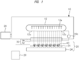
- FIG. 1 is a schematic cross-sectional view showing an electron-beam irradiator of the present embodiment.
- the electron-beam irradiator (sterilizing device) shown in FIG. 1 includes an electron-beam generator unit 10 and an irradiation chamber 20.
- a process-target object (irradiation-target object such as a raw egg) 40 arranged in the irradiation chamber 20 is irradiated with the electron beam through an irradiation window unit (irradiation window) 30 arranged in the electron-beam generator unit 10.
- the process-target object 40 is arranged on a delivery unit 21 such as a conveyor and is delivered. In the present embodiment, the process-target object 40 is delivered while rotating on the delivery unit 21.
- the process-target object 40 When the process-target object 40 is delivered while rotating and is also irradiated with the electron beam, its entire surface is evenly irradiated with the electron beam, so that the sterilizing effect based on the electron beam can be provided to the entire surface, and, as a result, the influence of the bremsstrahlung X ray on the eatable part caused by the irradiation with the electron beam can be made small.
- the electron-beam generator unit 10 includes a terminal 12 generating the electron beam inside a chamber and a space (acceleration space) where the electron beam that is generated in the terminal 12 is accelerated. And, the space (acceleration space) of the electron-beam generator unit 10 is kept in a vacuum state of about 10 -3 to 10 -5 Pa by a vacuum exhaust system 28 in order to prevent energy loss due to collision of the electrons with gas molecules and prevent oxidation of a filament 12a.
- the terminal 12 includes the linear filament 12a releasing thermal electrons and a grid 12c controlling the thermal electrons generated in the filament 12a.
- the electron-beam generator unit 10 includes a heating power supply (not illustrated) for use in heating the filament 12a to generate the thermal electrons, a controlling direct-current power supply (not illustrated) applying a voltage to a gap between the filament 12a and the grid 12c, and an accelerating direct-current power supply 16c applying a voltage (acceleration voltage) to a gap between the grid 12c and a window foil 32 arranged in the irradiation window unit 30.
- the irradiation chamber 20 includes an irradiation space where the process-target object (irradiation-target object) 40 is irradiated with the electron beam.
- the process-target object 40 is delivered inside the irradiation chamber 20 by a delivery unit 21 such as a conveyor in a direction, for example, from a depth side of a sheet of FIG. 1 toward a front side of the same.
- a beam collector 24 is arranged inside the irradiation chamber 20. This beam collector 24 absorbs the electron beam penetrating the process-target object 40.
- the electron-beam generator unit 10 and the irradiation chamber 20 are covered by a lead shielding plate so as to prevent the X ray that is secondarily generated at the time of the irradiation with the electron beam from leaking out.
- the inside of the irradiation chamber 20 is under atmosphere of an inert gas, air or others in accordance with a process content.
- the irradiation atmosphere inside the irradiation chamber 20 is set to be under the air (atmosphere containing oxygen), and the process-target object is sterilized by the electron beam.
- ozone is generated from the oxygen by the electron-beam irradiation, and then, is reacted with nitrogen in the air, so that NOx is generated. Since the NOx corrodes a metal foil (window foil 32), the generation of the NOx can be controlled by blowing of dry air from a blower 29 into the irradiation chamber 20.
- the irradiation window unit (irradiation window) 30 includes the window foil 32 made of the metal foil and a window frame unit 34 made of copper.
- the window frame unit 34 is used for supporting the window foil 32.
- a rectangular-shaped (quadrangular-shaped) opening is formed in the window frame unit 34.
- a width of the opening is, for example, about 1 cm, and its longitudinal direction is arranged in a direction that is orthogonal to the deliver direction.
- a cooling passage (not illustrated) is formed in order to cool the window foil 32, a temperature of which is increased by the electron-beam irradiation.
- the window frame unit 34 is detachably attached to the irradiation opening of the electron-beam generator unit 10.
- the window foil 32 is detachably adhered to a lower surface of the window frame unit 34.
- a metal foil such as an aluminum foil or a titanium (Ti) foil is used.
- the filament 12a is heated through the electric current by the heating power supply, the filament 12a releases the thermal electrons, and the released thermal electrons are attracted everywhere by a control voltage of the controlling direct-current power supply applied between the filament 12a and the grid 12c.
- the thermal electrons only thermal electrons that pass the grid 12c are effectively extracted as the electron beam.
- the electron beam that is extracted from the grid 12c is accelerated in the acceleration space by an acceleration voltage of the accelerating direct-current power supply 16c applied between the grid 12c and the window foil 32, and then, penetrates the window foil 32, and the process-target object that is delivered while rotating inside the irradiation chamber 20 below the irradiation window unit 30 is irradiated with the electron beam.
- an electric current value generated by the flow of the electron beam extracted from the grid 12c is referred to as beam electric current. The larger the beam electric current is, the more the electron beam is.
- predetermined values are set to the acceleration voltage, the beam electric current, a delivery speed (irradiation time) of the process-target object, a distance between the electron-beam irradiator unit and the process-target object and others, and then, the electron-beam irradiation process is performed to the process-target object.
- the energy applied on the electron beam is defined by the acceleration voltage. In other words, the higher the acceleration voltage is, the larger the resultant kinetic energy of the electron beam is. As a result, the electron beam can reach a portion ranging from the surface of the process-target object to the deep position. Therefore, by the change in the setting value of the acceleration voltage, the penetrating depth of the electron beam in the process-target object can be adjusted.
- an amount of the energy on the process-target object at the time of the electron-beam irradiation of the process-target object is expressed by a value referred to as absorbed dose (simply referred to as dose in some cases).
- the absorbed dose on the process-target object is, for example, in proportion to the beam electric current but inverse proportion to the delivery speed of the process-target object. Therefore, the absorbed dose of the electron beam can be adjusted by, for example, change in the irradiation condition such as the beam electric current or the delivery speed of the process-target object.
- the beam electric current is the value of the electric current generated by the flow of the electron beam extracted from the grid 12c.
- FIG. 2 is a perspective view showing a configuration of the delivery unit for use in the electron-beam irradiator (sterilizing device) of the present embodiment
- FIGs. 3 and 4 are cross-sectional schematic views of the delivery unit in a Y direction and an X direction, respectively.
- the delivery unit 21 has a plurality of rollers 21a extending in the Y direction that is orthogonal to the delivery direction (in this case, the X direction) .
- the roller 21a has a plurality of lanes L.
- the roller 21a has a shaft 21d and circular truncated cone members 21c arranged on both ends of the shaft 21d at the lane L, and there is a space (gap) 21b between the circular truncated cone members 21c.
- the circular truncated cone member 21c is arranged so as to be gradually thinner toward the space (gap) 21b.
- the process-target object (in this case, the raw egg) 40 is placed at each lane L so as to straddle these circular truncated cone members 21c on both sides of the space (gap) 21b.
- the process-target object (in this case, the raw egg) 40 rotates.
- the shaft 21d of the roller is joined to a chain or a belt (not illustrated) so as to be rotatable. By movement of this chain in the delivery direction (in this case, the X direction, see a dashed arrow), the process-target object (in this case, the raw egg) 40 is delivered in the X direction while rotating.
- the sterilizing process can be performed to the surface of the food by the electron-beam irradiation of the food having the shell or the outer skin covering the eatable part, that is the process-target object 40.
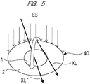
- FIG. 5 is a diagram schematically showing the sterilizing method of the present embodiment.
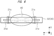
- FIG. 6 is a top view showing a state of the raw egg passing below the irradiation window unit (irradiation window).
- the raw egg (process-target object 40) having yolk 1 and albumen 2 is rotated, its eggshell is irradiated with the electron beam through the irradiation window unit (irradiation window) 30, so that the sterilization (such as the sterilization of the salmonella) can be performed in a range from the surface of the eggshell to a certain depth.
- the rectangular-shaped (quadrangular-shaped) opening of the irradiation window unit (irradiation window) 30 extends in the Y direction, and the shaft 21d of the roller also extends in the Y direction ( FIG. 6 ).
- a simulated egg specimen (a simulated raw-egg sample, an irradiation specimen) embedded with an RCD film dosimeter or a TLD element was fabricated, and was irradiated with the electron beam while rotating.
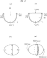
- FIG. 7 is a diagram showing the configuration of the raw egg.
- the raw egg has the eggshell 4, and the yolk 1 and the albumen 2 inside the eggshell.
- the yolk 1 and the albumen 2 are connected to each other by a chalaza 3.
- the eggshell 4 has a plurality of pores 6.
- the cuticular layer 5 can be removed by being washed.
- a blunt end of the raw egg has an air cell.
- FIG. 8 is a diagram showing steps of forming the irradiation specimen.
- the raw egg a surface of which was washed, (washed egg, M size) was prepared.
- a blunt-end eggshell and a sharp-end eggshell were obtained by cracking of the raw egg, followed by removal of the inner contents and the eggshell membrane and drying of the egg.
- the TLD element (TLD100: produced by Thermo Fisher Scientific, Inc.) shielded with a polyethylene film was arranged inside the sharp-end eggshell, and then, an agar "CD" of 2% was injected therein and solidified ( FIG. 8(a), (b )).
- the TLD element shielded with a polyethylene film was arranged inside the blunt-end eggshell, and then, an agar CD of 2% was injected therein and solidified ( FIG. 8 (a), (b )).
- the sharp-end specimen and the blunt-end specimen were combined with each other to become the irradiation specimen (the simulated raw-egg sample, the simulated specimen). As shown in FIG.
- the TLD element was at a sharp-end portion (P1) of the irradiation specimen (the simulated raw-egg sample, the simulated specimen), a blunt-end portion (P2) of the same, a center portion (P4) of the same, one end (P3) of a body of the same and the other end (P5) of the same.
- the body is an outer circumference of the raw egg (irradiation specimen) in a minor radius direction.
- An agar CD of 2% was injected into the sharp-end eggshell and solidified. Further, an agar CD of 2% was injected into the blunt-end eggshell and solidified.
- the sharp-end specimen and the blunt-end specimen were combined with each other to become the irradiation specimen (the simulated raw-egg sample, the simulated specimen).
- An RCD film dosimeter was wounded around the body (Round) of the irradiation specimen, and besides, an RCD film dosimeter was arranged on a blunt-end portion (Bottom) and a sharp-end portion (Top) ( FIG. 8(d) ).
- a low-energy electron beam irradiator (produced by IWASAKI ELECTRIC CO., LTD.: Eye Compact EB) was used for the irradiation with the electron beam having the acceleration voltage of 80 kV and the electric current of 0.1 mA.
- the roller (see FIGs. 3 and 4 ) was arranged below the irradiation window unit (irradiation window) of the low-energy electron beam irradiator, and the irradiation specimen was rotated and was also irradiated with the electron beam.
- FIG. 9 is a diagram showing a relation between the dose and the gap between the irradiation window unit and the irradiation specimen.
- FIG. 9(a) is a top view showing layouts of the irradiation window unit (irradiation window) and the RCD film dosimeter
- FIG. 9(b) is a graph showing the dose in the irradiation region measured by the RCD film dosimeter.
- a vertical axis of FIG. 9(b) indicates the dose (kGy), and a horizontal axis of the same indicates a position (cm) of the rectangular RCD film dosimeter.
- the rectangular RCD film dosimeter was arranged in a direction that is orthogonal to an extending direction of the rectangular irradiation window unit (irradiation window).
- the gap between the irradiation window unit (irradiation window) and the irradiation specimen was set to 3 cm.
- the gap between the irradiation window unit (irradiation window) and the irradiation specimen is preferable to be about 2 cm to 4 cm.
- FIG. 10 is a diagram (graph) showing the measurement results of the RCD film dosimeter (surface dose) in the comparative example without the rotation of the irradiation specimen.
- a horizontal axis indicates an angle [°]
- a vertical axis indicates the dose [kGy].
- the RCD film dosimeter was arranged in an upper-half circumference of the body of the irradiation specimen, and the measurement was made (see FIG. 10 ).
- FIG. 11 A measurement result of the RCD film dosimeter in the case in which the irradiation specimen was delivered while rotating when passed below the irradiation window unit (irradiation window) is shown in FIG. 11 .
- a numerical value surrounded by a square indicates the position of the RCD film dosimeter, and the remaining numerical values 0 to 4 indicate the dose intensity [kGy] .
- the gap between the irradiation window unit and the irradiation specimen was set to 3 cm
- the delivery speed was set to 2 m/minutes
- the rotation speed was set to 1.7 rotation/seconds.
- the body was more evenly irradiated with the electron beam than the comparative example.
- the RCD film dose surface dose was 3.4 kGy to 2.2 kGy.
- the maximum value in the comparative example FIG. 10
- the maximum value in the present working example FIG. 11
- the irradiation with the electron beam of 1 kGy decreases the amount of the salmonella down to 1/10000, and the irradiation with the electron beam of 3 kGy decreases the amount of the salmonella down to below the detection limit.
- the measurement results of the TLD dose (internal dose) in the case with the rotation of the irradiation specimen were P1: 7.4 mGy, P2: 9.0 mGy, P3: 11.3 mGy, P4: 9.0 mGy and P5: 10.6 mGy.
- the variations in the surface dose and the internal dose can be suppressed.
- the internal dose can be sufficiently reduced while the surface dose that is sufficient for the sterilization is maintained.
- the raw egg has been explained as the process-target object 40.
- the process-target object (irradiation-target object) needs to be only a food having an eatable part and a surface part (such as a shell or an outer skin) covering the eatable part, and the sterilizing device and the sterilizing method of the present embodiment can be preferably used for the sterilizing process of such foods.
- substantially spherical or oval spherical objects or cylindrical objects such as the oranges and the lemons are particularly easy to rotate, and the sterilizing method of the present embodiment is preferably used for these foods.
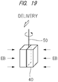
- the process-target object 40 is delivered while rotating by shaft rotation of a suspending member 50 such as a bar or a rope below which the process-target object 40 is suspended as shown in FIG. 19 and is also irradiated with the electron beam EB from a lateral side, so that the sterilizing process can be performed.
- FIG. 19 is a diagram schematically showing another sterilizing method.
- the acceleration voltage was set to 80 kV.
- the acceleration voltage can be adjusted in a range that is, for example, equal to or higher than 80 kV and equal to or lower than 150 kV.
- the surface dose was set to about 3 kGy.
- the surface dose can be adjusted in a range that is, for example, equal to or higher than 0.1 kGy and equal to or lower than 10 kGy.
- the rotation speed of the food that is the process-target object is preferably 0.3 rotation/seconds to 2.5 rotation/seconds.
- the delivery speed of the food that is the process-target object is preferably 0.1 m/minutes to 3 m/minutes.
- the rectangular (quadrangular) opening of the irradiation window unit (irradiation window) 30 extends in the Y direction, and the shaft 21d of the roller also extends in the Y direction.
- the extending direction (Y direction) of the rectangular (quadrangular) opening of the irradiation window unit (irradiation window) 30 coincides with a direction (Y direction) connecting the blunt-end portion (Bottom) and the sharp-end portion (Top) of the raw egg.
- the irradiation with the electron beam is inclined with respect to a direction that is orthogonal to the rotating direction of the food in a planar view. That is, the rectangular (quadrangular) opening of the irradiation window unit (irradiation window) 30 is inclined with respect to the extending direction (Y direction) of the shaft 21d of the roller.
- the extending direction of the rectangular (quadrangular) opening of the irradiation window unit (irradiation window) 30 and the extending direction (Y direction) of the shaft 21d of the roller cross each other at an angle in a range that is larger than 0° and equal to or smaller than 90°.
- this case is similar to the first embodiment (see FIG. 1 and others) except that the irradiation window unit (irradiation window) 30 is inclined. Also, regarding the sterilizing method, this case is similar to the first embodiment except that the process-target object (irradiation-target object such as the raw egg) 40 is irradiated with the electron beam EB from the inclined irradiation window unit (irradiation window) 30.
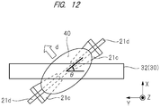
- FIG. 12 is a top view showing a state of the raw egg passing below the irradiation window unit (irradiation window) .
- the angle that is made by the extending direction of the rectangular (quadrangular) opening of the irradiation window unit (irradiation window) 30 and the extending direction (Y direction) of the shaft 21d of the roller is expressed as "0° ⁇ ⁇ ⁇ 90°".
- a term "d" indicates a delivery direction.
- the dose of the electron beam on the end portions (the blunt-end portion (Bottom) and the sharp-end portion (Top)) of the raw egg can be increased.
- the irradiation specimen embedded with the TLD element and the irradiation specimen embedded with the RCD film dosimeter were fabricated (see FIGs. 8(c) and (d )).
- the low-energy electron beam irradiator was used for the irradiation with the electron beam having the acceleration voltage of 80 kV and the electric current of 0.1 mA.
- the roller (see FIGs. 3 and 4 ) was arranged below the irradiation window unit (irradiation window) of the low-energy electron accelerator, and the rotating irradiation specimen was irradiated with the electron beam.
- the sterilizing process was performed to the egg under the condition in which 0°, 30° or 60° was set as the angle made by the extending direction of the rectangular (quadrangular) opening of the irradiation window unit (irradiation window) 30 and the extending direction (Y direction) of the shaft 21d of the roller.
- the case of "0°" corresponds to the cases of the first embodiment and the working example 1.
- each dose of the blunt-end portion (Bottom) and the sharp-end portion (Top) is expressed as an average of two points, the dose of the blunt-end portion (Bottom) is an average of 0.86 kGy and 1.27 kGy, and the dose of the sharp-end portion (Top) is an average of 0.55 kGy and 0.75 kGy.
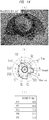
- (a) is a diagram (picture) showing a state of the inclination
- (b) is a graph showing the RCD film dose (surface dose)
- (c) is a table showing the TLD dose (internal dose).
- the internal doses in all cases are equal to or lower than 100 mGy, and clear the standards of, for example, 100 mGy.
- the difference in the surface dose between the body portion and the end portion of the raw egg can be made small, and the irradiation with the electron beam can be made more even.
- the angle ( ⁇ ) made by the irradiation window unit (irradiation window) and the axis (in the direction connecting the blunt-end portion (Bottom) and the sharp-end portion (Top)) of the raw egg is "0° ⁇ ⁇ ⁇ 90°", is preferably "0° ⁇ ⁇ ⁇ 60°", and is more preferably nearly 30° so as to be, for example, equal to or larger than 20° and equal to or smaller than 40°.
- the irradiation window unit (irradiation window) 30 is horizontal.
- the irradiation window unit (irradiation window) 30 may be inclined in an up and down direction (Z direction) .
- Z direction Z direction
- a left end of the irradiation window unit (irradiation window) in the drawing may be higher than a right end of the irradiation window unit (irradiation window) in the drawing.
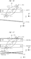
- FIG. 16 is a top view showing a state of the raw egg passing below the irradiation window unit (irradiation window) of the present application example.
- the number of the irradiation window unit (irradiation window) 30 is one.
- the irradiation with the electron beam may be made from two irradiation window units (irradiation windows).
- irradiation window units (irradiation windows) 30a and 30b are arranged, and a left end of the irradiation window unit (irradiation window) 30a in the drawing is arranged to be lower than a right end of the irradiation window unit in the drawing while a left end of the irradiation window unit (irradiation window) 30b in the drawing is arranged to be higher than a right end of the irradiation window unit in the drawing.
- FIG. 17 is a top view showing a state of the raw egg passing below the irradiation window units (irradiation windows) of the present application example.
- a term “32a” indicates a window foil arranged in an irradiation window unit 30a
- a term “32b” indicates a window foil arranged in an irradiation window unit 30b.
- the Particle and Heavy Ion Transport code System PHITS (Version 3.02) was used for creation of the egg models having SS to LL sizes on a weight basis.
- a density of the eggshell (main component: CaCO 3 ) was set to 2.0 because of having the pores, a density of the eatable part was set to be equal to that of water, and the atmosphere was set to the standard air, and then, the dose distributions of the electron beam and the bremsstrahlung X ray in the irradiation with the electron beam having the acceleration voltage of 80 keV to the egg were evaluated on a simulation basis.
- FIG. 18 is a diagram showing the electron-beam model and the bremsstrahlung X-ray model for the egg having the SS size.
- FIG. 18(a) is the electron-beam model
- FIG. 18(b) is the bremsstrahlung X-ray model.
- a table 1 shows a comparison data of the average absorbed dose on the eatable part of the egg having each size.
- the maximum increase dose was 16%. Therefore, when the eggs having the SS to LL sizes are randomly sterilized, it is preferable to estimate the internal dose to be safer (increase) by about 20%.
Landscapes
- Life Sciences & Earth Sciences (AREA)
- Engineering & Computer Science (AREA)
- Wood Science & Technology (AREA)
- Zoology (AREA)
- Chemical & Material Sciences (AREA)
- Food Science & Technology (AREA)
- Polymers & Plastics (AREA)
- Food Preservation Except Freezing, Refrigeration, And Drying (AREA)
- Apparatus For Disinfection Or Sterilisation (AREA)
Applications Claiming Priority (2)
| Application Number | Priority Date | Filing Date | Title |
|---|---|---|---|
| JP2019015305A JP7265246B2 (ja) | 2019-01-31 | 2019-01-31 | 殺菌装置および殺菌方法 |
| PCT/JP2019/046674 WO2020158149A1 (fr) | 2019-01-31 | 2019-11-28 | Dispositif de stérilisation et procédé de stérilisation |
Publications (2)
| Publication Number | Publication Date |
|---|---|
| EP3918921A1 true EP3918921A1 (fr) | 2021-12-08 |
| EP3918921A4 EP3918921A4 (fr) | 2022-09-21 |
Family
ID=71842106
Family Applications (1)
| Application Number | Title | Priority Date | Filing Date |
|---|---|---|---|
| EP19913769.6A Pending EP3918921A4 (fr) | 2019-01-31 | 2019-11-28 | Dispositif de stérilisation et procédé de stérilisation |
Country Status (4)
| Country | Link |
|---|---|
| EP (1) | EP3918921A4 (fr) |
| JP (1) | JP7265246B2 (fr) |
| CN (1) | CN113347887B (fr) |
| WO (1) | WO2020158149A1 (fr) |
Families Citing this family (9)
| Publication number | Priority date | Publication date | Assignee | Title |
|---|---|---|---|---|
| JP7491561B2 (ja) * | 2020-08-07 | 2024-05-28 | 地方独立行政法人東京都立産業技術研究センター | 殺菌装置および殺菌方法 |
| CN112023069B (zh) * | 2020-08-28 | 2023-12-01 | 同威信达技术(江苏)股份有限公司 | 一种电子束辐照种蛋表面的灭菌装置及其灭菌方法 |
| CN112023068A (zh) * | 2020-08-28 | 2020-12-04 | 江苏同威信达技术有限公司 | 一种对蛋类蛋壳表面的灭菌处理设备 |
| CN114831176B (zh) * | 2021-02-02 | 2023-08-04 | 湖州超群电子科技有限公司 | 一种利用电子束辐照对粮食杀菌消毒的系统及方法 |
| KR102653104B1 (ko) * | 2021-05-25 | 2024-03-29 | 씨제이제일제당 (주) | 파티클 저감을 위한 물류장치 |
| CN113304286A (zh) * | 2021-06-10 | 2021-08-27 | 大连大学 | 一种用于整车消毒及冷链产品消杀的自动化组合装置 |
| CN114129745A (zh) * | 2021-12-07 | 2022-03-04 | 新疆全安药业股份有限公司 | 一种行气坦尼卡尔胶囊的灭菌工艺 |
| CN115918715B (zh) * | 2022-12-23 | 2025-03-11 | 江南大学 | 基于圆环型磁路的感应电场蛋液杀菌方法 |
| CN116458658A (zh) * | 2023-03-17 | 2023-07-21 | 华南理工大学 | 一种低能x射线杀灭沙门氏菌的方法 |
Family Cites Families (9)
| Publication number | Priority date | Publication date | Assignee | Title |
|---|---|---|---|---|
| JP3096730B2 (ja) * | 1996-12-05 | 2000-10-10 | 農林水産省食品総合研究所長 | 穀物の殺菌方法 |
| JP3079516B2 (ja) * | 1998-09-30 | 2000-08-21 | 農林水産省食品総合研究所長 | 食品原料の連続殺菌方法 |
| JP2002045159A (ja) * | 2000-08-04 | 2002-02-12 | Mitsubishi Heavy Ind Ltd | 電子線殺菌装置 |
| JP3959996B2 (ja) * | 2001-09-26 | 2007-08-15 | 株式会社Nhvコーポレーション | 電子線照射装置 |
| JP4103699B2 (ja) * | 2003-06-30 | 2008-06-18 | 株式会社Nhvコーポレーション | 電子線照射装置 |
| JP5061680B2 (ja) | 2007-03-26 | 2012-10-31 | 澁谷工業株式会社 | 電子線殺菌装置 |
| JP6657830B2 (ja) * | 2015-11-18 | 2020-03-04 | 大日本印刷株式会社 | スパウト付き袋の殺菌方法及び装置並びにスパウト付き袋の無菌充填方法及び装置 |
| DE102016008291B3 (de) * | 2016-07-01 | 2017-11-02 | Evonta-Technology Gmbh | Verfahren und Vorrichtung zur Behandlung von Eiern von Geflügel mit Elektronenstrahlen für eine Sterilisation der Kalkschale |
| RU2654622C1 (ru) * | 2017-01-10 | 2018-05-21 | Федеральное государственное бюджетное учреждение науки Институт электрофизики Уральского отделения Российской академии наук (ИЭФ УрО РАН) | Способ поверхностной дезинфекции яйца |
-
2019
- 2019-01-31 JP JP2019015305A patent/JP7265246B2/ja active Active
- 2019-11-28 EP EP19913769.6A patent/EP3918921A4/fr active Pending
- 2019-11-28 CN CN201980089893.2A patent/CN113347887B/zh active Active
- 2019-11-28 WO PCT/JP2019/046674 patent/WO2020158149A1/fr not_active Ceased
Also Published As
| Publication number | Publication date |
|---|---|
| JP7265246B2 (ja) | 2023-04-26 |
| CN113347887A (zh) | 2021-09-03 |
| JP2020120621A (ja) | 2020-08-13 |
| WO2020158149A1 (fr) | 2020-08-06 |
| EP3918921A4 (fr) | 2022-09-21 |
| CN113347887B (zh) | 2024-09-27 |
Similar Documents
| Publication | Publication Date | Title |
|---|---|---|
| EP3918921A1 (fr) | Dispositif de stérilisation et procédé de stérilisation | |
| RU2748497C2 (ru) | Способ и устройство обработки яиц птицы при помощи лучей электронов для стерилизации известковой оболочки | |
| JP2007521819A (ja) | 包装済み食品中の微生物を制御する方法 | |
| WO2019204627A1 (fr) | Traitement par ultraviolets de produits alimentaires pour tuer des micro-organismes tout en conservant la floraison de fruit | |
| CN116761552A (zh) | 辐照设备 | |
| CN116113330B (zh) | 杀菌装置以及杀菌方法 | |
| Kim et al. | Simulation of pathogen inactivation in whole and fresh-cut cantaloupe (Cucumis melo) using electron beam treatment | |
| Niemira | Irradiation, microwave, and alternative energy-based treatments for low-water activity foods | |
| JP7030325B2 (ja) | 殺菌方法 | |
| Sokovnin | Food surface radiation sterilization | |
| US20230390433A1 (en) | An irradiation apparatus | |
| US8472584B2 (en) | Apparatus and method for killing pathogenic and non-pathogenic organisms using low-energy X-rays | |
| HK40053236A (en) | Sterilization device and sterilization method | |
| HK40053236B (zh) | 杀菌装置以及杀菌方法 | |
| JPH06317700A (ja) | 電子線照射装置 | |
| US8008640B2 (en) | Maxim electron scatter chamber | |
| Özer | Application of Electron Beam Irradiation Technique for Shelf-Life Extension of Animal Food Products | |
| Wagner et al. | Dose characterization of the rad sourceTM 2400 X-ray irradiator for oyster pasteurization | |
| RU2655806C1 (ru) | Блок радиационной обработки объектов (варианты) | |
| EP4729427A1 (fr) | Stérilisation par faisceau d'électrons et lumière uv combinées d'une bande de matériau d'emballage à l'intérieur d'une machine d'emballage | |
| Egorov et al. | On the application of pulsed beams with a wide electron kinetic energy spectrum | |
| Jongsoon et al. | Simulation of gamma-ray irradiation of lettuce leaves in a 137 Cs irradiator using MCNP | |
| Ley | Technological aspects of food irradiation with particular reference to Salmonellae elimination | |
| McHugh et al. | Illuminating E-beam processing | |
| Chakrabarty et al. | Dosimetric Characterization of 10 MeV Electron Accelerator Developed by BARC for Food Irradiation |
Legal Events
| Date | Code | Title | Description |
|---|---|---|---|
| STAA | Information on the status of an ep patent application or granted ep patent |
Free format text: STATUS: THE INTERNATIONAL PUBLICATION HAS BEEN MADE |
|
| PUAI | Public reference made under article 153(3) epc to a published international application that has entered the european phase |
Free format text: ORIGINAL CODE: 0009012 |
|
| STAA | Information on the status of an ep patent application or granted ep patent |
Free format text: STATUS: REQUEST FOR EXAMINATION WAS MADE |
|
| 17P | Request for examination filed |
Effective date: 20210726 |
|
| AK | Designated contracting states |
Kind code of ref document: A1 Designated state(s): AL AT BE BG CH CY CZ DE DK EE ES FI FR GB GR HR HU IE IS IT LI LT LU LV MC MK MT NL NO PL PT RO RS SE SI SK SM TR |
|
| DAV | Request for validation of the european patent (deleted) | ||
| DAX | Request for extension of the european patent (deleted) | ||
| A4 | Supplementary search report drawn up and despatched |
Effective date: 20220819 |
|
| RIC1 | Information provided on ipc code assigned before grant |
Ipc: A23B 5/015 20060101ALI20220815BHEP Ipc: A23L 3/26 20060101AFI20220815BHEP |
|
| STAA | Information on the status of an ep patent application or granted ep patent |
Free format text: STATUS: EXAMINATION IS IN PROGRESS |
|
| 17Q | First examination report despatched |
Effective date: 20251022 |
|
| REG | Reference to a national code |
Ref country code: DE Ref legal event code: R079 Free format text: PREVIOUS MAIN CLASS: A23L0003260000 Ipc: A23B0005015000 |
|
| GRAP | Despatch of communication of intention to grant a patent |
Free format text: ORIGINAL CODE: EPIDOSNIGR1 |
|
| STAA | Information on the status of an ep patent application or granted ep patent |
Free format text: STATUS: GRANT OF PATENT IS INTENDED |
|
| RIC1 | Information provided on ipc code assigned before grant |
Ipc: A23B 5/015 20060101AFI20260203BHEP Ipc: A23B 2/50 20250101ALI20260203BHEP |
|
| INTG | Intention to grant announced |
Effective date: 20260212 |