EP3918966A2 - Spender für desinfektionsmittel - Google Patents
Spender für desinfektionsmittel Download PDFInfo
- Publication number
- EP3918966A2 EP3918966A2 EP21176390.9A EP21176390A EP3918966A2 EP 3918966 A2 EP3918966 A2 EP 3918966A2 EP 21176390 A EP21176390 A EP 21176390A EP 3918966 A2 EP3918966 A2 EP 3918966A2
- Authority
- EP
- European Patent Office
- Prior art keywords
- sanitiser
- dispenser
- wall
- accordance
- housing
- Prior art date
- Legal status (The legal status is an assumption and is not a legal conclusion. Google has not performed a legal analysis and makes no representation as to the accuracy of the status listed.)
- Withdrawn
Links
Images






Classifications
-
- B—PERFORMING OPERATIONS; TRANSPORTING
- B65—CONVEYING; PACKING; STORING; HANDLING THIN OR FILAMENTARY MATERIAL
- B65D—CONTAINERS FOR STORAGE OR TRANSPORT OF ARTICLES OR MATERIALS, e.g. BAGS, BARRELS, BOTTLES, BOXES, CANS, CARTONS, CRATES, DRUMS, JARS, TANKS, HOPPERS, FORWARDING CONTAINERS; ACCESSORIES, CLOSURES, OR FITTINGS THEREFOR; PACKAGING ELEMENTS; PACKAGES
- B65D35/00—Pliable tubular containers adapted to be permanently or temporarily deformed to expel contents, e.g. collapsible tubes for toothpaste or other plastic or semi-liquid material; Holders therefor
- B65D35/56—Holders for collapsible tubes
-
- B—PERFORMING OPERATIONS; TRANSPORTING
- B65—CONVEYING; PACKING; STORING; HANDLING THIN OR FILAMENTARY MATERIAL
- B65D—CONTAINERS FOR STORAGE OR TRANSPORT OF ARTICLES OR MATERIALS, e.g. BAGS, BARRELS, BOTTLES, BOXES, CANS, CARTONS, CRATES, DRUMS, JARS, TANKS, HOPPERS, FORWARDING CONTAINERS; ACCESSORIES, CLOSURES, OR FITTINGS THEREFOR; PACKAGING ELEMENTS; PACKAGES
- B65D77/00—Packages formed by enclosing articles or materials in preformed containers, e.g. boxes, cartons, sacks or bags
- B65D77/04—Articles or materials enclosed in two or more containers disposed one within another
- B65D77/06—Liquids or semi-liquids or other materials or articles enclosed in flexible containers disposed within rigid containers
-
- A—HUMAN NECESSITIES
- A47—FURNITURE; DOMESTIC ARTICLES OR APPLIANCES; COFFEE MILLS; SPICE MILLS; SUCTION CLEANERS IN GENERAL
- A47K—SANITARY EQUIPMENT; ACCESSORIES THEREFOR, e.g. TOILET ACCESSORIES
- A47K5/00—Holders or dispensers for soap, toothpaste or the like
- A47K5/06—Dispensers for soap
- A47K5/12—Dispensers for soap for liquid or pasty soap
- A47K5/1201—Dispensers for soap for liquid or pasty soap hand-carried
-
- A—HUMAN NECESSITIES
- A47—FURNITURE; DOMESTIC ARTICLES OR APPLIANCES; COFFEE MILLS; SPICE MILLS; SUCTION CLEANERS IN GENERAL
- A47K—SANITARY EQUIPMENT; ACCESSORIES THEREFOR, e.g. TOILET ACCESSORIES
- A47K5/00—Holders or dispensers for soap, toothpaste or the like
- A47K5/06—Dispensers for soap
- A47K5/12—Dispensers for soap for liquid or pasty soap
- A47K5/1202—Dispensers for soap for liquid or pasty soap dispensing dosed volume
- A47K5/1208—Dispensers for soap for liquid or pasty soap dispensing dosed volume by means of a flexible dispensing chamber
-
- A—HUMAN NECESSITIES
- A61—MEDICAL OR VETERINARY SCIENCE; HYGIENE
- A61L—METHODS OR APPARATUS FOR STERILISING MATERIALS OR OBJECTS IN GENERAL; DISINFECTION, STERILISATION OR DEODORISATION OF AIR; CHEMICAL ASPECTS OF BANDAGES, DRESSINGS, ABSORBENT PADS OR SURGICAL ARTICLES; MATERIALS FOR BANDAGES, DRESSINGS, ABSORBENT PADS OR SURGICAL ARTICLES
- A61L2/00—Disinfection or sterilisation of materials or objects, in general; Accessories therefor
- A61L2/16—Disinfection or sterilisation of materials or objects, in general; Accessories therefor using chemical substances
- A61L2/18—Liquid substances
-
- A—HUMAN NECESSITIES
- A61—MEDICAL OR VETERINARY SCIENCE; HYGIENE
- A61L—METHODS OR APPARATUS FOR STERILISING MATERIALS OR OBJECTS IN GENERAL; DISINFECTION, STERILISATION OR DEODORISATION OF AIR; CHEMICAL ASPECTS OF BANDAGES, DRESSINGS, ABSORBENT PADS OR SURGICAL ARTICLES; MATERIALS FOR BANDAGES, DRESSINGS, ABSORBENT PADS OR SURGICAL ARTICLES
- A61L2/00—Disinfection or sterilisation of materials or objects, in general; Accessories therefor
- A61L2/26—Accessories
-
- B—PERFORMING OPERATIONS; TRANSPORTING
- B65—CONVEYING; PACKING; STORING; HANDLING THIN OR FILAMENTARY MATERIAL
- B65D—CONTAINERS FOR STORAGE OR TRANSPORT OF ARTICLES OR MATERIALS, e.g. BAGS, BARRELS, BOTTLES, BOXES, CANS, CARTONS, CRATES, DRUMS, JARS, TANKS, HOPPERS, FORWARDING CONTAINERS; ACCESSORIES, CLOSURES, OR FITTINGS THEREFOR; PACKAGING ELEMENTS; PACKAGES
- B65D83/00—Containers or packages with special means for dispensing contents
- B65D83/771—Containers or packages with special means for dispensing contents for dispensing fluent contents by means of a flexible bag or a deformable membrane or diaphragm
-
- A—HUMAN NECESSITIES
- A45—HAND OR TRAVELLING ARTICLES
- A45D—HAIRDRESSING OR SHAVING EQUIPMENT; EQUIPMENT FOR COSMETICS OR COSMETIC TREATMENTS, e.g. FOR MANICURING OR PEDICURING
- A45D34/00—Containers or accessories specially adapted for handling liquid toiletry or cosmetic substances, e.g. perfumes
- A45D2034/005—Containers or accessories specially adapted for handling liquid toiletry or cosmetic substances, e.g. perfumes with a cartridge
-
- A—HUMAN NECESSITIES
- A61—MEDICAL OR VETERINARY SCIENCE; HYGIENE
- A61L—METHODS OR APPARATUS FOR STERILISING MATERIALS OR OBJECTS IN GENERAL; DISINFECTION, STERILISATION OR DEODORISATION OF AIR; CHEMICAL ASPECTS OF BANDAGES, DRESSINGS, ABSORBENT PADS OR SURGICAL ARTICLES; MATERIALS FOR BANDAGES, DRESSINGS, ABSORBENT PADS OR SURGICAL ARTICLES
- A61L2202/00—Aspects relating to methods or apparatus for disinfecting or sterilising materials or objects
- A61L2202/10—Apparatus features
- A61L2202/15—Biocide distribution means, e.g. nozzles, pumps, manifolds, fans, baffles, sprayers
-
- A—HUMAN NECESSITIES
- A61—MEDICAL OR VETERINARY SCIENCE; HYGIENE
- A61M—DEVICES FOR INTRODUCING MEDIA INTO, OR ONTO, THE BODY; DEVICES FOR TRANSDUCING BODY MEDIA OR FOR TAKING MEDIA FROM THE BODY; DEVICES FOR PRODUCING OR ENDING SLEEP OR STUPOR
- A61M35/00—Devices for applying media, e.g. remedies, on the human body
- A61M35/003—Portable hand-held applicators having means for dispensing or spreading integral media
-
- B—PERFORMING OPERATIONS; TRANSPORTING
- B05—SPRAYING OR ATOMISING IN GENERAL; APPLYING FLUENT MATERIALS TO SURFACES, IN GENERAL
- B05B—SPRAYING APPARATUS; ATOMISING APPARATUS; NOZZLES
- B05B11/00—Single-unit hand-held apparatus in which flow of contents is produced by the muscular force of the operator at the moment of use
- B05B11/0005—Components or details
- B05B11/0078—Arrangements for separately storing several components
-
- B—PERFORMING OPERATIONS; TRANSPORTING
- B65—CONVEYING; PACKING; STORING; HANDLING THIN OR FILAMENTARY MATERIAL
- B65D—CONTAINERS FOR STORAGE OR TRANSPORT OF ARTICLES OR MATERIALS, e.g. BAGS, BARRELS, BOTTLES, BOXES, CANS, CARTONS, CRATES, DRUMS, JARS, TANKS, HOPPERS, FORWARDING CONTAINERS; ACCESSORIES, CLOSURES, OR FITTINGS THEREFOR; PACKAGING ELEMENTS; PACKAGES
- B65D1/00—Rigid or semi-rigid containers having bodies formed in one piece, e.g. by casting metallic material, by moulding plastics, by blowing vitreous material, by throwing ceramic material, by moulding pulped fibrous material or by deep-drawing operations performed on sheet material
- B65D1/09—Ampoules
- B65D1/095—Ampoules made of flexible material
-
- B—PERFORMING OPERATIONS; TRANSPORTING
- B65—CONVEYING; PACKING; STORING; HANDLING THIN OR FILAMENTARY MATERIAL
- B65D—CONTAINERS FOR STORAGE OR TRANSPORT OF ARTICLES OR MATERIALS, e.g. BAGS, BARRELS, BOTTLES, BOXES, CANS, CARTONS, CRATES, DRUMS, JARS, TANKS, HOPPERS, FORWARDING CONTAINERS; ACCESSORIES, CLOSURES, OR FITTINGS THEREFOR; PACKAGING ELEMENTS; PACKAGES
- B65D25/00—Details of other kinds or types of rigid or semi-rigid containers
- B65D25/02—Internal fittings
- B65D25/04—Partitions
-
- B—PERFORMING OPERATIONS; TRANSPORTING
- B65—CONVEYING; PACKING; STORING; HANDLING THIN OR FILAMENTARY MATERIAL
- B65D—CONTAINERS FOR STORAGE OR TRANSPORT OF ARTICLES OR MATERIALS, e.g. BAGS, BARRELS, BOTTLES, BOXES, CANS, CARTONS, CRATES, DRUMS, JARS, TANKS, HOPPERS, FORWARDING CONTAINERS; ACCESSORIES, CLOSURES, OR FITTINGS THEREFOR; PACKAGING ELEMENTS; PACKAGES
- B65D35/00—Pliable tubular containers adapted to be permanently or temporarily deformed to expel contents, e.g. collapsible tubes for toothpaste or other plastic or semi-liquid material; Holders therefor
- B65D35/24—Pliable tubular containers adapted to be permanently or temporarily deformed to expel contents, e.g. collapsible tubes for toothpaste or other plastic or semi-liquid material; Holders therefor with auxiliary devices
- B65D35/28—Pliable tubular containers adapted to be permanently or temporarily deformed to expel contents, e.g. collapsible tubes for toothpaste or other plastic or semi-liquid material; Holders therefor with auxiliary devices for expelling contents
-
- B—PERFORMING OPERATIONS; TRANSPORTING
- B65—CONVEYING; PACKING; STORING; HANDLING THIN OR FILAMENTARY MATERIAL
- B65D—CONTAINERS FOR STORAGE OR TRANSPORT OF ARTICLES OR MATERIALS, e.g. BAGS, BARRELS, BOTTLES, BOXES, CANS, CARTONS, CRATES, DRUMS, JARS, TANKS, HOPPERS, FORWARDING CONTAINERS; ACCESSORIES, CLOSURES, OR FITTINGS THEREFOR; PACKAGING ELEMENTS; PACKAGES
- B65D47/00—Closures with filling and discharging, or with discharging, devices
- B65D47/04—Closures with discharging devices other than pumps
- B65D47/06—Closures with discharging devices other than pumps with pouring spouts or tubes; with discharge nozzles or passages
- B65D47/065—Closures with discharging devices other than pumps with pouring spouts or tubes; with discharge nozzles or passages with hinged, foldable or pivotable spouts
- B65D47/066—Closures with discharging devices other than pumps with pouring spouts or tubes; with discharge nozzles or passages with hinged, foldable or pivotable spouts the spout being either flexible or having a flexible wall portion, whereby the spout is foldable between a dispensing and a non-dispensing position
Definitions
- the present invention relates to a device for dispensing a quantity of sanitiser and a bottle for refilling the dispenser.
- sanitiser to disinfect the hands or other objects.
- Such sanitiser is generally provided in a liquid form which can be dispensed from a conventional bottle or tube through a standard nozzle.
- a standard nozzle In order to effectively sanitise the hands in public places, it is necessary to carry this type of bottle or tube around, which can be inconvenient.
- the present invention relates to a dispenser having a construction such that it can be easily attached to another object in a convenient location and an associated refill bottle.
- the dispenser provides for easy application of a quantity of sanitiser and can be refilled and re-used as required.
- a sanitiser dispenser comprising:
- each of the dispensing members is connected to a neck portion of the corresponding pouch and the closure mechanism comprises rotational mounting of the dispensing member such that the dispensing member is rotatable from the closed position in which the neck portion of the pouch is folded and the open position in which the neck portion is unfolded to allow fluid within the pouch to flow into a hole in the dispensing member connected by a conduit to the aperture.
- the housing comprises upper and lower walls connected by a relatively short edge wall.
- the chambers comprise elongate chambers extending between the upper and lower walls from a first side of the housing to a second side of the housing for receiving the pouches, the pouches being elongate in shape.
- the edge wall comprises a side portion connecting between the upper and lower walls adjacent the second side of the housing and first and second end portions connecting between the upper and lower walls adjacent the first and second ends respectively.
- a plurality of dividing walls are provided between the upper and lower walls extending generally between the first and second sides of the housing to define the chambers.
- a cross member is provided extending between the first and second end portions of the edge wall, the cross member being offset from the first side of the housing and wherein the upper wall extends from the side portion of the edge wall to the cross member to define the openings.
- each of the pouches passes under the cross member to be adjacent the corresponding opening.
- each of the dispensing members is connected between adjacent dividing walls, or between one of the dividing walls and the adjacent first or second end portion of the edge wall, such that the dispensing member is rotatable between the open and closed positions.
- the aperture is provided in a first end of the dispensing member and the hole is provided in a first side of the dispensing member.
- the first side of the dispensing member is located adjacent the lower wall of the housing such that the neck portion of the pouch is in the folded configuration and, in the open position, the dispensing member extends outwardly from the first side of the housing such that the first side thereof faces upwardly away from the upper wall and neck portion of the pouch is in the unfolded configuration.
- a refill bottle comprising:
- the first and second side walls are circular such that the refill bottle comprises a relatively thin circular container.
- the applicator nozzle includes a cylindrical base mounted for rotation within a recess in the base portion and an elongate neck extending outwardly from the cylindrical base.
- the elongate neck includes a closed distal end and a hole in a side thereof from which sanitising fluid may be dispensed.
- the base portion extends inwardly from the periphery of the first side wall and the groove extends around the base portion
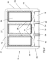
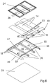
- a sanitiser dispenser 10 comprising generally a housing 12 including a plurality of pouches 14. Each of the pouches 14 comprises a flexible receptacle provided for receiving a fluid, such as a sanitising fluid.
- the housing 12 includes a plurality of chambers 18. Each of the chambers 18 is provided for receiving one of the pouches 14.
- the housing 12 includes also an opening 20 for each of the chambers 18 such that the opening 20 provides access to an end of the chamber 18.
- each of the pouches 14 is elongate and each of the chambers 18 is also generally elongate such that the shape of the chamber 18 generally corresponds with the shape of the pouch 14.
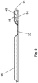
- a neck portion 22 of each of the pouches 14, through which the interior of the pouch 14 is accessible, is located in use adjacent the corresponding opening 20 in the housing 12.
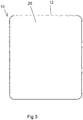
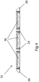
- the housing 12 includes upper and lower walls 24 and 25. Each of the upper and lower walls 24 and 25 are located adjacent each other such that the housing 12 is relatively thin. In the embodiment shown, the upper and lower walls 24 and 25 are rectangular in shape such that the defined housing 12 includes first and second sides 26 and 27 and first and second ends 28 and 29.
- a relatively short edge wall 30 extends between the upper and lower walls 24 and 25 such that the upper and lower walls 24 and 25 are supported apart to define the interior of the housing 12.
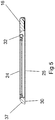
- the edge wall 30 (as best seen in Figure 6 ) comprises a side portion 37 connecting between the upper and lower walls 24 and 25 adjacent the second side 27 of the housing 10 and first and second end portions 38 and 39 connecting between the upper and lower walls 24 and 25 adjacent the first and second ends 28 and 29 of the housing 12 respectively.
- a plurality of dividing walls 34 are provided between the upper and lower walls 24 and 25 extending generally across between the first and second sides 26 and 27 of the housing 10.
- the dividing walls 34 define the chambers 18 such that the chambers 18 are elongate and extend between the first and second sides 26 and 27 of the housing 10. In the embodiment shown, there are provided three such dividing walls 34 to form four chambers 18 for receiving the pouches 14.
- a cross member 32 is provided extending between the first and second end portions 38 and 39 of the edge wall 30.
- the cross member 32 is offset from the first side 26 of the housing 10 and the upper wall 24 extends from the side portion 37 of the edge wall 30 to the cross member 32 such that the upper wall 24 is narrower than the lower wall 25.
- the openings 20 are thereby defined by the narrower upper wall 24 and the open side of the edge wall 30 adjacent the first side 26 of the housing 10.
- the cross member 32 is connected to the first and second end portions 38 and 39 of the edge wall 30 and the dividing walls 34 adjacent upper edges thereof such that a neck portion 22 of each of the pouches 14 may pass under the cross member 32 to be adjacent the corresponding opening 20.
- the upper wall 24 comprises a flexible material, such as a suitable plastic material and includes a plurality of channels 36 therein.
- Each of the channels 18 is provided above one of the chambers 18 such that the upper wall 24 extends downwardly around the periphery of the chamber 18. The portions of the upper wall 24 within the channels 36 may thereby be more easily pressed downwardly to engage with the pouch 14 within the chamber 18.
- Each of the pouches 14 is provided with a dispensing member 16.
- the dispensing member 16 is secured across the neck portion 22 of the pouch 14 such that the dispensing member 16 seals the neck portion 22.
- Each of the dispensing members 16 includes an aperture 44 in a first end thereof.
- Each of the dispensing members 16 includes also a hole 46 in a first side thereof.
- the neck portion 22 of the pouch 14 is secured to the side of the dispensing member 16 such that the interior of the pouch 14 is in communication with the hole 46.
- the hole 46 is connected to the aperture 44 by a conduit 48 extending through the dispensing member 16.
- the dispensing members 16 are each provided with a closure mechanism in order to allow or restrict flow of the fluid outwardly via the dispensing member 16.
- Each of the dispensing members 16 is connected adjacent the opening 20 such that the dispensing members 16 is rotatable between a closed position (as can be seen for example in Figure 1 ) and an open position (as can be seen for example in Figure 7 ).
- Each of the dispensing members 16 is connected between the adjacent dividing walls 34, or the dividing wall 34 and the adjacent first or second end portion 38 or 39 of the edge wall 30, such that the dispensing member 16 is rotatable between the open and closed positions.
- the dispensing members 16 include lugs 40 on opposite sides thereof to be received in indents 42 in the adjacent dividing wall 34 or first or second end portion 38 or 29 of the edge wall 30.
- the first side of the dispensing member 16 is located adjacent the lower wall 25 of the housing 12 such that the neck portion 22 of the pouch 14 is in a folded configuration.
- the dispensing member 16 extends outwardly from the first side 26 of the housing 12 such that the first side thereof faces upwardly away from the upper wall 24 and the neck portion 22 of the pouch 14 is in an unfolded configuration.
- the first end of the dispensing member 16 in which the aperture 44 is provided is located adjacent the cross member 32. In the open position, the first end of the dispensing member 16 is located outwardly away from the first side 26 of the housing 12.
- the folded neck portions 22 of the pouches 14 retain sanitiser fluid within the pouches 14.
- the dispensing member 16 is rotated to the open position to unfold the neck portion 22 of the pouch 14.
- the upper wall 24 of the housing 12 is formed from a slightly flexible material such that the upper wall 14 may be pressed in order to compress the pouch 14 and thereby squeeze the sanitising fluid into the hole 46 and outwardly through the aperture 44 via the conduit 48. A single dose of sanitising fluid may therefore easily be dispensed from one of the pouches 14 which then can be subsequently closed by returning the dispensing member 16 to the closed position.
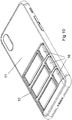
- the housing 12 of the sanitiser dispenser 10 may be conveniently attached to any suitable object by securing the lower wall 25 with a suitable adhesive.
- the housing 12 may, for example, be secured to a rear side of a mobile phone 11 or phone case provided on the phone 11, as shown in Figure 10 .
- the sanitiser dispenser 10 will therefore be readily available for use without the requirement for carrying a separate bottle or tube of sanitiser.
- the lower wall 25 may itself comprise a sheet of adhesive tape, such as double-sided tape such that the cover can be peeled off the adhesive tape layer to stick down sanitiser dispenser 10.
- a refill bottle 50 (as shown in Figures 11 to 17 ) is provided for storing a larger quantity of sanitising fluid to allow refilling of each of the pouches 14.
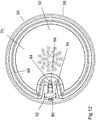
- the refill bottle 50 comprises first and second side walls 52 and 53 connected around the periphery thereof by an edge wall 56.
- the first and second side walls 52 and 53 are circular and the edge wall 56 is relatively short such that the refill bottle 50 comprises a relatively thin circular container.
- the refill bottle 50 includes an applicator nozzle 58 from which a sanitising fluid may be dispensed in order to refill the pouches 14 of the sanitiser dispenser 10.
- the applicator nozzle 58 is pivotally mounted to a base portion 54 provided in the first side wall 52 of the refill bottle 50.
- the base portion 54 extends inwardly from the periphery of the first side wall 52.
- An upper surface of the base portion 54 includes a recess 60 in which the applicator nozzle 58 is mounted.
- the applicator nozzle 58 includes a cylindrical base 62 mounted for rotation within the recess 60 and an elongate neck 64 extending outwardly from the cylindrical base 62.
- the applicator nozzle 58 can be rotated about the cylindrical base 62 between a retracted position (as shown in Figure 11 ) and an extended position (as shown in Figures 15 to 17 ). In the extended position, the elongate neck 64 extends outwardly from the recess 60 such that it may be received into the aperture 44 of the dispensing member 16.
- They elongate neck 64 includes a closed distal end and a dispensing hole 66 in a side thereof (as can be seen in Figure 16 ) such that, when inserted into the aperture 44, sanitising fluid may flow from the dispensing hole 66 in the elongate neck 64 through the conduit 48 and then out of the hole 46 into the into the pouch 14.
- the pouch 14 may also include an internal tube extending from the dispensing member 16 to an end of the pouch 14 remote from the dispensing member 16.
- the tube is in communication with the aperture 44 such that fluid passes from the refill bottle 50 through tube to enter the interior of the pouch 14 at the end remote from the dispensing member 16.
- This arrangement may be provided to fill the pouch 14 from the end remote from the dispensing member 16 to reduce the likelihood of an airlock being formed while refilling of the pouch 14.
- the first side wall 52 of the refill bottle 50 includes a groove 68 around the periphery thereof.
- the groove 68 extends around the first side wall 52 and passes around the base portion 54.
- the groove 68 defines a central wall portion 70 in the first side wall 52.
- the central wall portion 70 is formed from a relatively rigid material and the groove 68 is formed from a relatively flexible material such that the central wall portion 70 may be depressed inwardly towards the second side wall 53 by deforming the groove 68.
- the central wall portion 70 may therefore be depressed inwardly in order to pump sanitising fluid out through the applicator nozzle 58.
- the refill bottle 50 may therefore be used to store a larger quantity of sanitising fluid and may be engaged with each of the dispensing members 16 in order to refill the pouches 14 with sanitising fluid as required.
- the refill bottle 50 may be provided in two parts. As can be seen in Figure 14 , the first part comprises the first side wall 52 and a first portion of the edge wall 56 and the second part comprises the second side wall 53 and a second portion of the edge wall 56. The first and second parts may be connected together by threaded engagement between the first and second portions of the edge wall 56. The refill bottle 50 may then be separated into the two parts for filling. In an alternative embodiment (not shown), the refill bottle 50 may be provided with a refill opening having a removable cap.
Landscapes
- Health & Medical Sciences (AREA)
- Public Health (AREA)
- Engineering & Computer Science (AREA)
- Mechanical Engineering (AREA)
- General Health & Medical Sciences (AREA)
- Animal Behavior & Ethology (AREA)
- Life Sciences & Earth Sciences (AREA)
- Epidemiology (AREA)
- Veterinary Medicine (AREA)
- Chemical & Material Sciences (AREA)
- Chemical Kinetics & Catalysis (AREA)
- General Chemical & Material Sciences (AREA)
- Containers And Packaging Bodies Having A Special Means To Remove Contents (AREA)
- Packages (AREA)
Applications Claiming Priority (1)
| Application Number | Priority Date | Filing Date | Title |
|---|---|---|---|
| AU2020901859A AU2020901859A0 (en) | 2020-06-05 | Sanitiser Dispenser and Refill Bottle |
Publications (2)
| Publication Number | Publication Date |
|---|---|
| EP3918966A2 true EP3918966A2 (de) | 2021-12-08 |
| EP3918966A3 EP3918966A3 (de) | 2022-02-23 |
Family
ID=75260707
Family Applications (1)
| Application Number | Title | Priority Date | Filing Date |
|---|---|---|---|
| EP21176390.9A Withdrawn EP3918966A3 (de) | 2020-06-05 | 2021-05-27 | Spender für desinfektionsmittel |
Country Status (5)
| Country | Link |
|---|---|
| US (1) | US20210378455A1 (de) |
| EP (1) | EP3918966A3 (de) |
| CN (2) | CN113753404A (de) |
| AU (1) | AU2021203471A1 (de) |
| BR (1) | BR102021010848A2 (de) |
Family Cites Families (4)
| Publication number | Priority date | Publication date | Assignee | Title |
|---|---|---|---|---|
| US3194440A (en) * | 1963-10-11 | 1965-07-13 | Jr Cornelins B Watson | Plurality of tube squeezers and holder therefor |
| JP2004299743A (ja) * | 2003-03-31 | 2004-10-28 | Yoshino Kogyosho Co Ltd | 押出し容器 |
| US8844766B2 (en) * | 2009-07-14 | 2014-09-30 | Sterilogy, Llc | Dispenser assembly for dispensing disinfectant fluid and data collection and monitoring system for monitoring and reporting dispensing events |
| US9211987B2 (en) * | 2013-02-20 | 2015-12-15 | Dow Global Technologies Llc | Flexible pouch and dock system |
-
2020
- 2020-10-09 US US17/067,444 patent/US20210378455A1/en not_active Abandoned
- 2020-10-16 CN CN202011108353.5A patent/CN113753404A/zh active Pending
- 2020-10-16 CN CN202022318623.7U patent/CN212891805U/zh not_active Expired - Fee Related
-
2021
- 2021-05-27 AU AU2021203471A patent/AU2021203471A1/en not_active Abandoned
- 2021-05-27 EP EP21176390.9A patent/EP3918966A3/de not_active Withdrawn
- 2021-06-04 BR BR102021010848-7A patent/BR102021010848A2/pt not_active Application Discontinuation
Also Published As
| Publication number | Publication date |
|---|---|
| CN113753404A (zh) | 2021-12-07 |
| EP3918966A3 (de) | 2022-02-23 |
| AU2021203471A1 (en) | 2021-12-23 |
| US20210378455A1 (en) | 2021-12-09 |
| CN212891805U (zh) | 2021-04-06 |
| BR102021010848A2 (pt) | 2021-12-21 |
Similar Documents
| Publication | Publication Date | Title |
|---|---|---|
| KR100502224B1 (ko) | 소형 유체 펌프 | |
| EP1114606B1 (de) | Satz enthaltend einen Spender und eine gefügige Tasche | |
| US8251075B2 (en) | Cosmetic compact | |
| EP1444050B1 (de) | Medienspender, dessen gehäuse, behälter zum einsatz darin und anordnung zum dosierten pumpen eines mediums aus einem behälter | |
| US7258251B2 (en) | Multi-chambered dispensing container | |
| JP3364319B2 (ja) | 製品分与ユニット | |
| US20090241584A1 (en) | Multi-spigot cooler | |
| US20050006408A1 (en) | Foam dispenser, housing and storage holder therefor | |
| AU2002343848A1 (en) | Dispenser for dispensing a fluid, housing for such a dispenser, storage holder destined for placement therein and arrangement for the dosed pumping of a fluid from a fluid reservoir | |
| US10723537B2 (en) | Cartridge pump | |
| US7753087B2 (en) | Product dispensing system | |
| CN111699048B (zh) | 双泵分配系统 | |
| JP2007119069A (ja) | 持運び式液体分与器 | |
| US10189040B2 (en) | Dispensing device | |
| US20220048056A1 (en) | Liquid dispenser | |
| EP3918966A2 (de) | Spender für desinfektionsmittel | |
| WO2022190691A1 (ja) | 流体吐出容器 | |
| JP3681614B2 (ja) | 小量吐出容器 | |
| CN215687335U (zh) | 一种自动出液装置的容器、给皂装置及储物柜 | |
| KR102888427B1 (ko) | 치과 인상 재료용 카트리지 | |
| AU2004242481A1 (en) | Container | |
| GB2612842A (en) | Improvements in refillable liquid dispenser devices |
Legal Events
| Date | Code | Title | Description |
|---|---|---|---|
| PUAI | Public reference made under article 153(3) epc to a published international application that has entered the european phase |
Free format text: ORIGINAL CODE: 0009012 |
|
| STAA | Information on the status of an ep patent application or granted ep patent |
Free format text: STATUS: THE APPLICATION HAS BEEN PUBLISHED |
|
| AK | Designated contracting states |
Kind code of ref document: A2 Designated state(s): AL AT BE BG CH CY CZ DE DK EE ES FI FR GB GR HR HU IE IS IT LI LT LU LV MC MK MT NL NO PL PT RO RS SE SI SK SM TR |
|
| PUAL | Search report despatched |
Free format text: ORIGINAL CODE: 0009013 |
|
| AK | Designated contracting states |
Kind code of ref document: A3 Designated state(s): AL AT BE BG CH CY CZ DE DK EE ES FI FR GB GR HR HU IE IS IT LI LT LU LV MC MK MT NL NO PL PT RO RS SE SI SK SM TR |
|
| RIC1 | Information provided on ipc code assigned before grant |
Ipc: A47K 5/12 20060101AFI20220119BHEP |
|
| STAA | Information on the status of an ep patent application or granted ep patent |
Free format text: STATUS: THE APPLICATION IS DEEMED TO BE WITHDRAWN |
|
| 18D | Application deemed to be withdrawn |
Effective date: 20220824 |