EP3919320A1 - Procédé de gestion thermique pour ensemble de batteries - Google Patents
Procédé de gestion thermique pour ensemble de batteries Download PDFInfo
- Publication number
- EP3919320A1 EP3919320A1 EP20850104.9A EP20850104A EP3919320A1 EP 3919320 A1 EP3919320 A1 EP 3919320A1 EP 20850104 A EP20850104 A EP 20850104A EP 3919320 A1 EP3919320 A1 EP 3919320A1
- Authority
- EP
- European Patent Office
- Prior art keywords
- battery pack
- thermal management
- time
- condition
- under
- Prior art date
- Legal status (The legal status is an assumption and is not a legal conclusion. Google has not performed a legal analysis and makes no representation as to the accuracy of the status listed.)
- Granted
Links
Images



Classifications
-
- B—PERFORMING OPERATIONS; TRANSPORTING
- B60—VEHICLES IN GENERAL
- B60L—PROPULSION OF ELECTRICALLY-PROPELLED VEHICLES; SUPPLYING ELECTRIC POWER FOR AUXILIARY EQUIPMENT OF ELECTRICALLY-PROPELLED VEHICLES; ELECTRODYNAMIC BRAKE SYSTEMS FOR VEHICLES IN GENERAL; MAGNETIC SUSPENSION OR LEVITATION FOR VEHICLES; MONITORING OPERATING VARIABLES OF ELECTRICALLY-PROPELLED VEHICLES; ELECTRIC SAFETY DEVICES FOR ELECTRICALLY-PROPELLED VEHICLES
- B60L58/00—Methods or circuit arrangements for monitoring or controlling batteries or fuel cells, specially adapted for electric vehicles
- B60L58/10—Methods or circuit arrangements for monitoring or controlling batteries or fuel cells, specially adapted for electric vehicles for monitoring or controlling batteries
- B60L58/12—Methods or circuit arrangements for monitoring or controlling batteries or fuel cells, specially adapted for electric vehicles for monitoring or controlling batteries responding to state of charge [SoC]
-
- B—PERFORMING OPERATIONS; TRANSPORTING
- B60—VEHICLES IN GENERAL
- B60L—PROPULSION OF ELECTRICALLY-PROPELLED VEHICLES; SUPPLYING ELECTRIC POWER FOR AUXILIARY EQUIPMENT OF ELECTRICALLY-PROPELLED VEHICLES; ELECTRODYNAMIC BRAKE SYSTEMS FOR VEHICLES IN GENERAL; MAGNETIC SUSPENSION OR LEVITATION FOR VEHICLES; MONITORING OPERATING VARIABLES OF ELECTRICALLY-PROPELLED VEHICLES; ELECTRIC SAFETY DEVICES FOR ELECTRICALLY-PROPELLED VEHICLES
- B60L58/00—Methods or circuit arrangements for monitoring or controlling batteries or fuel cells, specially adapted for electric vehicles
- B60L58/10—Methods or circuit arrangements for monitoring or controlling batteries or fuel cells, specially adapted for electric vehicles for monitoring or controlling batteries
- B60L58/24—Methods or circuit arrangements for monitoring or controlling batteries or fuel cells, specially adapted for electric vehicles for monitoring or controlling batteries for controlling the temperature of batteries
-
- B—PERFORMING OPERATIONS; TRANSPORTING
- B60—VEHICLES IN GENERAL
- B60L—PROPULSION OF ELECTRICALLY-PROPELLED VEHICLES; SUPPLYING ELECTRIC POWER FOR AUXILIARY EQUIPMENT OF ELECTRICALLY-PROPELLED VEHICLES; ELECTRODYNAMIC BRAKE SYSTEMS FOR VEHICLES IN GENERAL; MAGNETIC SUSPENSION OR LEVITATION FOR VEHICLES; MONITORING OPERATING VARIABLES OF ELECTRICALLY-PROPELLED VEHICLES; ELECTRIC SAFETY DEVICES FOR ELECTRICALLY-PROPELLED VEHICLES
- B60L58/00—Methods or circuit arrangements for monitoring or controlling batteries or fuel cells, specially adapted for electric vehicles
- B60L58/10—Methods or circuit arrangements for monitoring or controlling batteries or fuel cells, specially adapted for electric vehicles for monitoring or controlling batteries
- B60L58/24—Methods or circuit arrangements for monitoring or controlling batteries or fuel cells, specially adapted for electric vehicles for monitoring or controlling batteries for controlling the temperature of batteries
- B60L58/26—Methods or circuit arrangements for monitoring or controlling batteries or fuel cells, specially adapted for electric vehicles for monitoring or controlling batteries for controlling the temperature of batteries by cooling
-
- B—PERFORMING OPERATIONS; TRANSPORTING
- B60—VEHICLES IN GENERAL
- B60L—PROPULSION OF ELECTRICALLY-PROPELLED VEHICLES; SUPPLYING ELECTRIC POWER FOR AUXILIARY EQUIPMENT OF ELECTRICALLY-PROPELLED VEHICLES; ELECTRODYNAMIC BRAKE SYSTEMS FOR VEHICLES IN GENERAL; MAGNETIC SUSPENSION OR LEVITATION FOR VEHICLES; MONITORING OPERATING VARIABLES OF ELECTRICALLY-PROPELLED VEHICLES; ELECTRIC SAFETY DEVICES FOR ELECTRICALLY-PROPELLED VEHICLES
- B60L58/00—Methods or circuit arrangements for monitoring or controlling batteries or fuel cells, specially adapted for electric vehicles
- B60L58/10—Methods or circuit arrangements for monitoring or controlling batteries or fuel cells, specially adapted for electric vehicles for monitoring or controlling batteries
- B60L58/24—Methods or circuit arrangements for monitoring or controlling batteries or fuel cells, specially adapted for electric vehicles for monitoring or controlling batteries for controlling the temperature of batteries
- B60L58/27—Methods or circuit arrangements for monitoring or controlling batteries or fuel cells, specially adapted for electric vehicles for monitoring or controlling batteries for controlling the temperature of batteries by heating
-
- G—PHYSICS
- G01—MEASURING; TESTING
- G01R—MEASURING ELECTRIC VARIABLES; MEASURING MAGNETIC VARIABLES
- G01R31/00—Arrangements for testing electric properties; Arrangements for locating electric faults; Arrangements for electrical testing characterised by what is being tested not provided for elsewhere
- G01R31/36—Arrangements for testing, measuring or monitoring the electrical condition of accumulators or electric batteries, e.g. capacity or state of charge [SoC]
- G01R31/3644—Constructional arrangements
- G01R31/3648—Constructional arrangements comprising digital calculation means, e.g. for performing an algorithm
-
- H—ELECTRICITY
- H01—ELECTRIC ELEMENTS
- H01M—PROCESSES OR MEANS, e.g. BATTERIES, FOR THE DIRECT CONVERSION OF CHEMICAL ENERGY INTO ELECTRICAL ENERGY
- H01M10/00—Secondary cells; Manufacture thereof
- H01M10/60—Heating or cooling; Temperature control
- H01M10/62—Heating or cooling; Temperature control specially adapted for specific applications
- H01M10/625—Vehicles
-
- B—PERFORMING OPERATIONS; TRANSPORTING
- B60—VEHICLES IN GENERAL
- B60L—PROPULSION OF ELECTRICALLY-PROPELLED VEHICLES; SUPPLYING ELECTRIC POWER FOR AUXILIARY EQUIPMENT OF ELECTRICALLY-PROPELLED VEHICLES; ELECTRODYNAMIC BRAKE SYSTEMS FOR VEHICLES IN GENERAL; MAGNETIC SUSPENSION OR LEVITATION FOR VEHICLES; MONITORING OPERATING VARIABLES OF ELECTRICALLY-PROPELLED VEHICLES; ELECTRIC SAFETY DEVICES FOR ELECTRICALLY-PROPELLED VEHICLES
- B60L2260/00—Operating Modes
- B60L2260/40—Control modes
- B60L2260/50—Control modes by future state prediction
- B60L2260/56—Temperature prediction, e.g. for pre-cooling
-
- B—PERFORMING OPERATIONS; TRANSPORTING
- B60—VEHICLES IN GENERAL
- B60L—PROPULSION OF ELECTRICALLY-PROPELLED VEHICLES; SUPPLYING ELECTRIC POWER FOR AUXILIARY EQUIPMENT OF ELECTRICALLY-PROPELLED VEHICLES; ELECTRODYNAMIC BRAKE SYSTEMS FOR VEHICLES IN GENERAL; MAGNETIC SUSPENSION OR LEVITATION FOR VEHICLES; MONITORING OPERATING VARIABLES OF ELECTRICALLY-PROPELLED VEHICLES; ELECTRIC SAFETY DEVICES FOR ELECTRICALLY-PROPELLED VEHICLES
- B60L2260/00—Operating Modes
- B60L2260/40—Control modes
- B60L2260/50—Control modes by future state prediction
- B60L2260/58—Departure time prediction
-
- Y—GENERAL TAGGING OF NEW TECHNOLOGICAL DEVELOPMENTS; GENERAL TAGGING OF CROSS-SECTIONAL TECHNOLOGIES SPANNING OVER SEVERAL SECTIONS OF THE IPC; TECHNICAL SUBJECTS COVERED BY FORMER USPC CROSS-REFERENCE ART COLLECTIONS [XRACs] AND DIGESTS
- Y02—TECHNOLOGIES OR APPLICATIONS FOR MITIGATION OR ADAPTATION AGAINST CLIMATE CHANGE
- Y02E—REDUCTION OF GREENHOUSE GAS [GHG] EMISSIONS, RELATED TO ENERGY GENERATION, TRANSMISSION OR DISTRIBUTION
- Y02E60/00—Enabling technologies; Technologies with a potential or indirect contribution to GHG emissions mitigation
- Y02E60/10—Energy storage using batteries
-
- Y—GENERAL TAGGING OF NEW TECHNOLOGICAL DEVELOPMENTS; GENERAL TAGGING OF CROSS-SECTIONAL TECHNOLOGIES SPANNING OVER SEVERAL SECTIONS OF THE IPC; TECHNICAL SUBJECTS COVERED BY FORMER USPC CROSS-REFERENCE ART COLLECTIONS [XRACs] AND DIGESTS
- Y02—TECHNOLOGIES OR APPLICATIONS FOR MITIGATION OR ADAPTATION AGAINST CLIMATE CHANGE
- Y02T—CLIMATE CHANGE MITIGATION TECHNOLOGIES RELATED TO TRANSPORTATION
- Y02T10/00—Road transport of goods or passengers
- Y02T10/60—Other road transportation technologies with climate change mitigation effect
- Y02T10/70—Energy storage systems for electromobility, e.g. batteries
Definitions
- This application relates to the field of new energy, and in particular to a thermal management method for a battery pack.
- the passenger compartment of the electric vehicle has a relatively great demand for heating, while in summer, the passenger compartment's demand for cooling consumes a lot of power, which will greatly reduce the driving mileage of the electric vehicle.
- the battery pack itself has a thermal management demand, if the thermal management is performed using the power of the power pack, the power consumption of the battery pack will be further increased.
- an intelligent thermal management method for the battery pack is needed to reduce the power consumption of the battery pack, thereby increasing the driving mileage of the battery pack.
- the present application provides a thermal management method for a battery pack to increase the driving mileage of the battery pack.
- a thermal management method for a battery pack includes:
- the target temperature of the battery pack is determined according to the connection state of the charging interface of the electric vehicle and the charging device, and if the charging interface is connected with the charging device, the battery pack can be heated by the charging device, so the target temperature of the battery pack can be set to be slightly higher. If the charging interface is not connected with the charging device, the target temperature of the battery pack can be set to be slightly lower, to avoid or reduce the power consumption of the battery pack as much as possible so as to increase the driving mileage of the battery pack.
- thermal management can be performed on the battery pack at a best time, which also avoids the power consumption of the battery pack and increases the driving mileage of the battery pack.
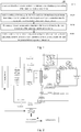
- Fig. 1 shows a schematic flowchart of a thermal management method 100 for a battery pack provided according to the present application.
- the thermal management method for a battery pack provided according to the present application includes the following steps:
- the power-on time of the battery pack is a starting time of the electric vehicle, that is, a travel time of a user.
- the thermal management method for the battery pack provided according to the present application can be applied to a battery management system (Battery Management System, BMS) of the battery pack.
- BMS Battery Management System
- the target temperature of the battery pack is determined according to the connection state of the charging interface of the electric vehicle and the charging device, and if the charging interface is connected with the charging device, the battery pack can be heated by the charging device, so the target temperature of the battery pack can be set to be slightly higher. If the charging interface is not connected with the charging device, the target temperature of the battery pack can be set to be slightly lower, to avoid or reduce the power consumption of the battery pack as much as possible so as to increase the driving mileage of the battery pack.
- the battery pack can be preheated or pre-cooled at a best time, which also avoids the power consumption of the battery pack and increases the driving mileage of the battery pack.
- the thermal management system of the electric vehicle includes a vehicle controller and a BMS.
- the double-headed arrow between the vehicle controller and the BMS represents that they can communicate in both directions.
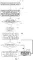
- step S110 the BMS can obtain the power-on time of the battery pack from the vehicle controller.
- step S110 when the vehicle controller detects that the electric vehicle stops running, that is, when the electric vehicle is in a stationary state, the BMS controls the vehicle controller to send first prompt information to an intelligent terminal about whether there is a travel demand. Under a condition that the vehicle controller receives feedback information sent by the intelligent terminal that the user does not have the travel demand, the BMS does not operate.
- the BMS controls the vehicle controller to send second prompt information to the intelligent terminal about whether there is a thermal management demand for the battery pack.
- the BMS does not operate.
- the BMS controls the vehicle controller to send third prompt information for setting a travel time to the intelligent terminal.
- the double-headed arrow between the vehicle controller and the intelligent terminal represents that they can communicate in both directions.
- the vehicle controller determines whether the user sets the travel time through the intelligent terminal. As an example, the vehicle controller can determine whether the user sets the travel time by whether it receives time information sent by the intelligent terminal within a preset time period to.
- the vehicle controller Under a condition that the vehicle controller receives the travel time set by the user returned by the intelligent terminal within the preset time period t 0 , the vehicle controller sends the travel time set by the user to the BMS.
- the BMS uses the received travel time as the power-on time of the battery pack.
- the vehicle controller under a condition that the vehicle controller does not receive the time information returned by the intelligent terminal within the preset time period t 0 , the vehicle controller analyzes pre-recorded user's travel habit information and traffic information of each travel, and calculates a travel time recommended to the user. The vehicle controller sends the recommended travel time to the intelligent terminal. Under a condition that the user accepts the recommended travel time through the intelligent terminal, the vehicle controller uses the recommended travel time as the power-on time of the battery pack. Under a condition that the user does not accept the recommended travel time, either of the vehicle controller and the BMS does not operate.
- the BMS determines whether the battery pack has a thermal management demand. As an example, in step S120, the BMS may determine whether the battery pack has a thermal management demand according to a temperature of the battery pack.
- the BMS firstly obtains a temperature T_bat of the battery pack, and then determines whether the battery pack has a thermal management demand according to the temperature T_bat of the battery pack, a first preset temperature threshold and a second preset temperature threshold.
- the first preset temperature threshold is determined based on a lowest operating temperature Temp1 of the battery pack
- the second preset temperature threshold is determined based on a highest operating temperature Temp2 of the battery pack.
- Temp1 is less than Temp2.
- the first preset temperature threshold is equal to the lowest operating temperature Temp1 of the battery pack
- the second preset temperature threshold is equal to the highest operating temperature Temp2 of the battery pack.
- the lowest operating temperature Temp1 of the battery pack refers to the lowest temperature of the battery pack under which the electric vehicle can operate normally.
- the highest temperature Temp2 of the battery pack refers to the highest temperature of the battery pack under which the electric vehicle can operate normally.
- the BMS re-obtains the temperature of the battery pack every preset time interval ⁇ t 0 , and continues to determine whether the battery pack has the thermal management demand according to the re-obtained temperature of the battery pack, the Temp1 and the Temp2.
- the thermal management demand of the battery pack includes a demand for cooling and a demand for heating.
- the BMS determines that the battery pack has the demand for heating; and under a condition of T_bat ⁇ Temp2, the BMS determines that the battery pack has the demand for cooling.
- step S120 when determining that the battery pack has the thermal management demand, the BMS determines the target temperature of the battery pack according to the connection state of the charging interface of the electric vehicle and the charging device.
- the charging device may be a charging pile.
- the BMS determines whether the charging interface of the electric vehicle is connected with the charging device.
- the BMS may determine whether the charging interface of the electric vehicle is connected with the charging device by determining whether it receives a wake-up signal sent by the charging device to indicate that the charging device itself has established a connection with the charging interface of the electric vehicle. Under a condition that the BMS receives the wake-up signal sent by the charging device, the BMS determines that the charging device is connected with the charging interface of the electric vehicle. Under a condition that the BMS does not receive the wake-up signal sent by the charging device, the BMS determines that the charging device is not connected with the charging interface of the electric vehicle.
- step S120 under a condition that the battery pack has the thermal management demand (regardless of a demand for heating or a demand for cooling) and the charging interface of the electric vehicle is connected with the charging device, the target temperature is set as a third preset temperature threshold.
- the target temperature is set as a fourth preset temperature threshold.
- the target temperature is set as a fifth preset temperature threshold.
- the fourth preset temperature threshold is less than the third preset temperature threshold
- the third preset temperature threshold is less than the fifth preset temperature threshold
- the third preset temperature threshold is an optimal operating temperature Temp3 of the battery pack
- the fourth preset temperature threshold is equal to the lowest operating temperature Temp1 of the battery pack
- the fifth preset temperature threshold is equal to the highest operating temperature Temp2 of the battery pack.
- the thermal management can be performed on the battery pack by virtue of the charging device to avoid power consumption of the battery pack, so the target temperature of the battery pack can be set as the optimal operating temperature Temp3 of the battery pack.
- the power of the battery pack itself may be needed to perform the thermal management on the battery pack.
- the target temperature of the battery pack is heated to the lowest operating temperature so that the electric vehicle can be started and operate.
- the target temperature of the battery pack is decreased to the highest operating temperature of the battery pack so that the electric vehicle can be started and operate.
- the target temperature of the battery pack is intelligently and reasonably set according to the connection state of the charging interface of the electric vehicle and the charging device, to avoid power consumption of the battery pack as much as possible so as to increase the driving mileage of the battery pack.
- the type of the thermal management demand of the battery pack and the connection state of the charging interface of the electric vehicle with the charging device not only affect the setting of the target temperature of the battery pack, but also affect the calculation of the thermal management starting time.
- the following will introduce the calculation process of the thermal management starting time according to different scenarios.
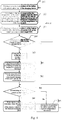
- Scenario 1 the battery pack has the demand for heating, and the charging interface of the electric vehicle is connected with the charging device.
- the BMS determines whether the charging device has a function of heating the battery pack.
- the charging device After the charging device is connected with the charging interface of the electric vehicle, the charging device will automatically reports its performance information to the BMS.
- the BMS may determine whether the charging device has a heating function according to heating identification information in the performance information reported by the charging device.
- the performance information reported by the charging device may further include information such as power information, charging device model, and charging current type.
- the heating identification information reported by the charging device may indicate whether the charging device has the heating function, so the BMS may determine whether the charging device has the heating function based on the received heating identification information of the charging device.
- Step A1 the BMS obtains a current temperature of the battery pack and a heating rate (i.e., a first heating rate) of the charging device.
- the BMS may obtain the first heating rate according to an obtained current state parameter of the battery pack and a pre-stored corresponding relationship between the state parameter of the battery pack and the heating rate.
- the first heating rate may also be a heating rate preset by the BMS.
- Step A2 the BMS calculates a duration t 1 required for the temperature of the battery pack to reach the third preset temperature threshold from the current temperature based on the obtained heating rate v 1 of the charging device, the third preset temperature threshold and the obtained current temperature To of the battery pack.
- an environmental temperature T env of the electric vehicle needs to be obtained firstly.
- the BMS may directly obtain the environmental temperature of the electric vehicle from a temperature sensor that measures the environmental temperature of the electric vehicle.
- the BMS may also receive the environmental temperature of the electric vehicle from the vehicle controller, and the vehicle controller may obtain the environmental temperature of the electric vehicle from an environmental temperature sensor disposed on the vehicle.
- the third preset temperature threshold is equal to the optimal operating temperature Temp3 of the battery pack
- v 2 is a heat conduction rate obtained by the BMS
- ⁇ 1 is a preset first correction coefficient
- ⁇ 2 is a preset second correction coefficient.
- the BMS may determine the heat conduction rate v 2 according to a pre-stored corresponding relationship between a temperature range and the heat conduction rate, which will not be repeated herein.
- Step A3 the BMS obtains a current state of charge (State of Charge, SOC) of the battery pack, and calculates a charging duration t 2 of the battery pack based on the current SOC of the battery pack and a preset target SOC of the battery pack.
- SOC state of Charge
- the BMS may calculate the charging duration of the battery pack using any known charging time calculation method, which will not be repeated herein.
- Step A4 the BMS obtains a current time, and determines whether a first time difference between a first time and the current time satisfies a preset criterion for determining thermal management starting time.
- the first time is before the power-on time of the battery pack, and a duration between the first time and the power-on time is equal to t 1 + t 2 .
- the power-on time is 14:00 on July 19, 2019, t 1 is equal to 10 minutes, and t 2 is equal to 20 minutes, then the first time is 13:30 on July 19, 2019.
- the first time is an estimated thermal management starting time. Under a condition that the time difference between the estimated thermal management starting time and the current time satisfies the preset criterion for determining thermal management starting time, the first time is determined as a final thermal management starting time. Under a condition that the time difference between the estimated thermal management starting time and the current time does not satisfy the preset criterion for determining thermal management starting time, t 1 + t 2 is re-calculated to re-estimate the thermal management starting time.
- the preset criterion for determining thermal management starting time is that the first time difference is less than a preset duration threshold.
- step A5 Under a condition that the first time difference satisfies the preset criterion for determining thermal management starting time, the process proceeds to step A5. Under a condition that the first time difference does not satisfy the preset criterion for determining thermal management starting time the process returns to step A1 after a second preset time interval ⁇ t 1 .
- the current temperature of the battery pack is updated, and t 1 and t 2 are updated based on the re-obtained current temperature of the battery pack, until the thermal management starting time of the battery pack is obtained.
- Step A5 the first time is used as the thermal management starting time.
- the double-headed arrow between the charging device and the BMS represents that they can communicate in both directions.
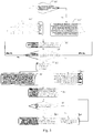
- the charging device is connected with the charging interface of the electric vehicle (not shown in Fig. 2 ), the charging interface of the electric vehicle is connected with the positive electrode of the battery pack through a charging positive electrode switch K1 and a heating switch K3 connected in series, and the charging interface of the electric vehicle is further connected with the negative electrode of the battery pack through a charging negative electrode switch K2 and a heating switch K4 connected in series.
- step S140 includes step B1 to step B5.
- Step B1 when the BMS determines that the thermal management starting time arrives, the BMS controls all of the charging positive electrode switch K1, the charging negative electrode switch K2, the heating switch K3 and the heating switch K4 to turn on, and sends a heating request including a heating parameter corresponding to the heating rate of the charging device to the charging device.
- the charging device may have a pulse heating function.
- the BMS may determine a pulse current signal parameter corresponding to the heating rate of the charging device according to a pre-stored corresponding relationship between the pulse current signal parameter and the heating rate.
- the BMS may send the pulse current signal parameter corresponding to the heating rate of the charging device to the charging device, for example, the pulse current signal parameter includes parameters such as a frequency of the pulse current signal and a duty ratio of the pulse current signal.
- the duty ratio of the pulse current signal refers to a ratio of the time during which the current direction is a positive direction to one cycle of the pulse current.
- the charging device After the charging device receives the pulse current signal parameter for pulse heating of the battery pack, the charging device provides a pulse current having the above pulse current signal parameter.
- the charging device and the battery pack constitute a pulse heating loop.
- an internal resistor of the battery pack itself may generate heat, thereby heating the battery pack.
- the charging device may also heat the battery pack by other heating means, which is not limited herein.
- Step B2 when the temperature of the battery pack is equal to the third preset temperature threshold, the charging device is controlled to charge the battery pack, until the SOC of the battery pack reaches the target SOC.
- the BMS monitors the temperature of the battery pack in real time, and under a condition that the temperature of the battery pack reaches the third preset temperature threshold, the thermal management on the battery pack is stopped.
- the BMS sends a charging request including a charging current to the charging device, and controls the charging device to charge the battery pack with this charging current, until the SOC of the battery pack reaches the preset target SOC.
- Step B3 when the power of the battery pack reaches a preset target power, it is determined whether the power-on time arrives. Under a condition that the power-on time arrives, the process proceeds to step B4, and under a condition that the power-on time does not arrive, the process proceeds to step B5.
- Step B4 under a condition that the electric vehicle is still in the stationary state, the process returns to step S110; and under a condition that the electric vehicle is started, the thermal management on the battery pack is stopped.
- the BMS controls the charging positive electrode switch K1 and the charging negative electrode switch K2 to turn off, and re-obtains the power-on time of the battery pack, that is, the process returns to step S110.
- the BMS controls the charging positive electrode switch K1 and the charging negative electrode switch K2 to turn off to stop performing the thermal management on the battery pack.
- Step B5 the temperature of the battery pack is maintained at the third preset temperature threshold.
- the BMS monitors the temperature of the battery pack in real time. Under a condition that a temperature difference between the temperature of the battery pack and the third preset temperature threshold satisfies a preset thermal management starting criterion, the BMS sends a heating request to the charging device, to control the charging device to heat the battery pack, until the temperature of the battery pack reaches the target temperature.
- the BMS controls the charging positive electrode switch K1 and the charging negative electrode switch K2 to turn off, to stop performing the thermal management on the battery pack so as to maintain the temperature of the battery pack at the target temperature.
- the process returns to step B3, until the power-on time arrives under the third preset temperature threshold.
- the preset thermal management starting criterion is that a difference of the target temperature minus the temperature of the battery pack is greater than a preset temperature difference threshold.
- the BMS determines that the charging device does not have the heating function.
- the battery pack may be heated using at least one of the following methods:
- the battery pack is heated by a self-heating function of the battery pack, by waste heat generated by a motor in the electric vehicle, and by energy obtained by the motor from the charging device.
- the following describes an implementation process of the self-heating function of the battery pack.
- the thermal management system for the battery pack further includes a switch K5 connected with the heating switch K3, a switch K6 connected with the heating switch K4, a switch drive component J connected between the switch K5 and the switch K6, a motor M connected with the switch drive component J, and a motor controller (not shown in Fig. 2 ).
- the switch drive component J and the motor controller are both located in an inverter.
- the switch drive component J includes power switch devices J1 to J6, and each power switch device has a corresponding parasitic diode.
- the switch K5 and the switch K6 are connected with a battery management unit (Battery Management Unit, BMU) (not shown in Fig. 2 ).
- BMU Battery Management Unit
- the power switch devices J1 to J6 are all connected with the motor controller (not shown in Fig. 2 ).
- the switch drive component J includes a first-phase arm, a second-phase arm and a third-phase arm connected in parallel.
- the first-phase arm, the second-phase arm and the third-phase arm each has an upper arm and a lower arm, each upper arm is provided with a power switch device, and each lower arm is also provided with a power switch device.
- the first-phase arm is a U-phase arm
- the second-phase arm is a V-phase arm
- the third-phase arm is a W-phase arm.
- the switch unit of the upper arm of the U-phase arm is the power switch device J1
- the lower arm of the U-phase arm is provided with the power switch device J2.
- the switch unit of the upper arm of the V-phase arm is the power switch device J3
- the switch unit of the lower arm of the V-phase arm is the power switch device J4.
- the switch unit of the upper arm of the W-phase arm is the power switch device J5, and the switch unit of the lower arm of the W-phase arm is the power switch device J6.
- the stator of the motor M is equivalent to three phases of stator inductors, that is, stator inductor L1, stator inductor L3, and stator inductor L5.
- stator inductor L1 stator inductor L1
- stator inductor L3 stator inductor L5
- stator inductor L5 is connected to a common end.
- a first-phase input end, a second-phase input end, and a third-phase input end of the motor M are respectively connected with a connection point of the upper arm and the lower arm of the first-phase arm, a connection point of the upper arm and the lower arm of the second-phase arm, and a connection point of the upper arm and the lower arm of the third-phase arm.
- a non-common end of the stator inductor L1 is the first-phase input end
- a non-common end of the stator inductor L3 is the second-phase input end
- a non-common end of the stator inductor L5 is the third-phase input end.
- the BMU When the BMU determines that the battery pack needs to be heated, the BMU sends a battery heating request to the vehicle controller. Under a condition of determining that the electric vehicle is in the stationary state and the motor is not operating, the vehicle controller sends a battery heating instruction to the motor controller according to the battery heating request. The motor controller establishes a communication with the BMU after receiving the battery heating instruction. Then, the BMU controls all of the heating switch K3, the heating switch K4, the switch K5 and the switch K6 to turn on, and controls the motor controller to provide drive signals for a power switch device of a target upper arm and a power switch device of a target lower arm, to control the power switch device of the target upper arm and the power switch device of the target lower arm to be periodically turned on and off.
- the drive signal may be a pulse signal.
- a high level in the drive signal can drive the power switch device to be turned on, and a low level signal in the drive signal can drive the power switch device to be turned off.
- the drive signal may control the power switch device of the target upper arm and the power switch device of the target lower arm to be periodically turned on and off.
- the power switch device of the target upper arm is the power switch device of the upper arm of any of the first-phase arm, the second-phase arm and the third-phase arm
- the power switch device of the target lower arm is the power switch device of the lower arm of at least one arm except the arm where the power switch device of the target upper arm is located.
- the drive signal drives the power switch device of the target upper arm and the power switch device of the target lower arm to be periodically turned on and off, thus an alternating current is generated in the loop formed by the battery pack, the heating switch K3, the switch K5, the power switch device of the target upper arm, the motor M, the power switch device of the target lower arm, the switch K6, and the heating switch K4.
- an alternating sinusoidal current may be generated. That is, the battery pack is charged and discharged alternately, which may generate a continuous alternating excitation current in a high-voltage loop where the battery pack is located, which flows continuously through the battery pack so that an internal resistor of the battery pack generates heat, which heats the battery from the inside.
- the following describes a process of heating the battery pack by heat generated by a motor in the electric vehicle.
- the thermal management system of the electric vehicle further includes a thermal management system of the battery pack, a cooling system of the motor, and an air-conditioning system.
- the thermal management system of the battery pack includes a water pump 1, a heat exchange plate and a first heat exchanger connected in series.
- the cooling system of the motor includes a motor radiator, a motor heat exchange device and a water pump 2 connected in series.
- the cooling system of the motor is connected with the thermal management system of the battery pack by a second heat exchanger.
- a first port of the second heat exchanger is connected with the water pump 1
- a second port of the second heat exchanger is connected with the water pump 2
- a third port of the second heat exchanger is connected with the first heat exchanger
- a fourth port of the second heat exchanger is connected with the motor radiator.
- the BMU controls all of the water pump 2, the water pump 1 and the second heat exchanger to be in an on-state, and the motor heat exchange device absorbs the heat generated by the motor into a cooling liquid of the cooling system of the motor.
- the cooling liquid after absorbing the heat in the cooling system of the motor flows through the second heat exchanger, the second heat exchanger transfers the heat in the cooling liquid in the cooling system of the motor to a cooling liquid in the battery management system.
- the heat exchange plate transfers the heat to the battery pack so as to heat the battery pack using the waste heat generated by the motor.
- the thermal management system of the electric vehicle further includes the air-conditioning system.
- the air-conditioning system includes a first evaporator, a compressor, a condenser and an expansion valve TXV1 connected in series.
- the air-conditioning system further includes an expansion valve TXV2 and a second evaporator connected in series.
- the second evaporator is connected with a common port of the first evaporator and the compressor
- the expansion valve TXV2 is connected with a common port of the expansion valve TXV1 and the condenser.
- the first evaporator is connected with the first heat exchanger and is used for absorbing heat transferred by the first heat exchanger to cool the battery pack.
- the BMU controls all of the expansion valve TXV1, the expansion valve TXV2 and the water pump 1 to be in an on-state, and controls the compressor to be in an on-state, then the heat generated by the battery pack is transferred to the cooling liquid in the thermal management system of the battery pack by the heat exchange plate.
- the first evaporator absorbs the heat transferred by the first heat exchanger, and the first evaporator, the compressor, the condenser and the expansion valve TXV1 form a cooling loop for cooling the battery pack.
- the second evaporator, the compressor, the condenser and the expansion valve TXV2 may form a cooling loop to cool a passenger compartment of the electric vehicle.
- the following describes an implementation process of heating the battery pack using energy obtained by the motor from the charging device.
- the BMS controls all of the charging positive electrode switch K1, the charging negative electrode switch K2, the switch K5 and the switch K6 to turn on, controls the heating switch K3 and the heating switch K4 to turn off, and controls the motor controller to provide the switch drive component J with a drive signal, to enable the power switch device of the target upper arm and the power switch device of the target lower arm to be turned on, so that the motor obtains energy from the charging device, and the stator inductors of the motor store the energy.
- the BMS controls the charging positive electrode switch K1 and the charging negative electrode switch K2 to turn off, controls all of the switch K5, the switch K6, the heating switch K3 and the heating switch K4 to turn on, and controls the motor controller to provide the switch drive component J with a drive signal, to enable the power switch device of the target upper arm and the power switch device of the target lower arm to be turned off.
- stator inductor corresponding to the power switch device of the target upper arm, the parasitic diode of the power switch device of the target upper arm, the switch K5, the heating switch K3, the battery pack, the heating switch K4, the switch K6, the parasitic diode of the power switch device of the target lower arm, and the stator inductor corresponding to the power switch device of the target lower arm constitute a charging loop of the battery pack, so that the energy stored in the motor heats the battery pack.
- step S130 includes step A1' to step A5.
- Step A1' whether the obtained current SOC of the battery pack satisfies a preset self-heating criterion is determined.
- step A2 Under a condition that the current SOC of the battery pack satisfies the preset self-heating criterion, the process proceeds to step A2'. Under a condition that the current SOC of the battery pack does not satisfy the preset self-heating criterion, the process proceeds to step A2".
- the preset self-heating criterion is that the current SOC of the battery pack is greater than a preset SOC threshold.
- Step A2' a duration t 1 required for the temperature of the battery pack to reach the third preset temperature threshold from the current temperature is calculated based on an obtained second heating rate, an obtained third heating rate, the third preset temperature threshold and the obtained current temperature of the battery pack.
- the battery pack under a condition that the current SOC of the battery pack satisfies the preset self-heating criterion, the battery pack may be heated using the self-heating function of the battery pack.
- the motor when the battery pack is self-heated, the motor generates heat, so the battery pack may also be heated using the waste heat of the motor. That is, when the self-heating function of the battery pack is started, the cooling system of the motor and the thermal management system of the battery pack may also be started, to heat the battery pack using the waste heat of the motor.
- a self-heating rate (second heating rate) of the battery pack and a heating rate (third heating rate) of the waste heat of the motor during the self-heating need to be obtained.
- the self-heating rate of the battery pack corresponding to the current state parameter of the battery pack may be obtained according to a pre-stored corresponding relationship between the state parameter of the battery pack and the self-heating rate of the battery pack.
- the heating rate of the waste heat of the motor corresponding to the current state parameter of the battery pack may also be obtained according to a pre-stored corresponding relationship between the state parameter of the battery pack and the heating rate of the waste heat of the motor.
- a heat conduction factor between the battery pack and an external environment also needs to be considered.
- the heating duration t 1 may be calculated using a method similar to equation (1) based on the self-heating rate of the battery pack, the heating rate of the waste heat of the motor, the heat conduction rate, the third preset temperature threshold and the current temperature of the battery pack, and the specific calculation process is not repeated herein.
- Step A2 the duration t 1 required for the temperature of the battery pack to reach the third preset temperature threshold from the current temperature is calculated based on an obtained fourth heating rate, an obtained fifth heating rate, the third preset temperature threshold and the obtained current temperature of the battery pack.
- the battery pack may be heated using the energy obtained by the motor from the charging device.
- the motor also generates waste heat, so the battery pack may also be heated using the waste heat of the motor.
- a heating rate (fourth heating rate) of heating the battery pack using the energy stored by the motor from the charging device and a heating rate (fifth heating rate) of the waste heat of the motor during the heating by the energy stored the motor need to be obtained.
- the fourth heating rate and the fifth heating rate may be pre-stored, and may also be queried according to a pre-stored corresponding relationship between the state parameter of the battery pack and the heating rate, which is not specifically limited herein.
- a heat conduction factor between the battery pack and an external environment also needs to be considered.
- the heating duration t 1 may be calculated using a method similar to equation (1) based on the fourth heating rate, the fifth heating rate, the heat conduction rate, the third preset temperature threshold and the current temperature of the battery pack, and the specific calculation process is not repeated herein.
- step A3 regardless of whether the current SOC of the battery pack satisfies the self-heating criterion of the battery, after the duration t 1 required for the temperature of the battery pack to reach the third preset temperature threshold from the current temperature is calculated, the process proceeds to step A3.
- Step A3 the BMS obtains a current SOC of the battery pack, and calculates a charging duration t 2 of the battery pack based on the current SOC of the battery pack and a preset target SOC of the battery pack.
- Step A4 the BMS obtains a current time, and determines whether a first time difference between a first time and the current time satisfies a preset criterion for determining thermal management starting time.
- step A5 Under a condition that the first time difference satisfies the preset criterion for determining thermal management starting time, the process proceeds to step A5.
- the process returns to step A2' after the second preset time interval ⁇ t 1 .
- t 1 and t 2 are updated using the updated current temperature of the battery pack, until the thermal management starting time of the battery pack is obtained.
- t 1 and t 2 are updated using the updated current temperature of the battery pack, until the thermal management starting time of the battery pack is obtained.
- Step A5 the first time is used as the thermal management starting time.
- step S140 includes step B1' and step B2 to step B5.
- step S140 includes step B1" and step B2 to step B5.
- Step Bl' the BMS controls the switch drive component of the motor in the electric vehicle to be periodically turned on and off so as to heat the battery pack, and controls the cooling system of the motor to be connected with the thermal management system of the battery pack so as to heat the battery pack using waste heat generated by the motor.
- the BMS controls all of the heating switch K3, the heating switch K4, the switch K5 and the switch K6 to turn on, and controls the motor controller to provide the switch drive component J with a drive signal, to control the switch drive component J of the motor in the electric vehicle to be periodically turned on and off so as to heat the battery pack.
- the BMS While controlling all of the heating switch K3, the heating switch K4, the switch K5 and the switch K6 to turn on, the BMS controls all of the water pump 1, the water pump 2 and the second heat exchanger to be in an on-state, to connect the cooling system of the motor with the thermal management system of the battery pack so as to heat the battery pack using waste heat generated by the motor during the self-heating.
- Step B1 the BMS controls the motor to store energy using the charging device, controls the motor to heat the battery pack using the energy stored by itself, and controls the cooling system of the motor to be connected with the thermal management system of the battery pack to heat the battery pack using waste heat generated by the motor.
- the BMS firstly controls all of the charging positive electrode switch K1, the charging negative electrode switch K2, the switch K5 and the switch K6 to turn on, controls the heating switch K3 and the heating switch K4 to turn off, and controls the motor controller to provide the switch drive component J with a drive signal, to enable the power switch device of the target upper arm and the power switch device of the target lower arm to be turned on, so that the motor obtains energy from the charging device, and the stator inductors of the motor store the energy.
- the BMS controls all of the water pump 1, the water pump 2 and the second heat exchanger to be in an on-state to connect the cooling system of the motor with the thermal management system of the battery pack so as to heat the battery pack using waste heat generated by the motor during heating of the battery pack using the energy stored by the motor.
- the BMS controls the charging positive electrode switch K1 and the charging negative electrode switch K2 to turn off, controls all of the switch K5, the switch K6, the heating switch K3 and the heating switch K4 to turn on, and controls the motor controller to provide the switch drive component J with a drive signal, to enable the power switch device of the target upper arm and the power switch device of the target lower arm to be turned off, so that the energy stored by the motor heats the battery pack.
- Step B2 when the temperature of the battery pack is equal to the third preset temperature threshold, the charging device is controlled to charge the battery pack, until the SOC of the battery pack reaches the target SOC.
- Step B3 when the power of the battery pack reaches a preset target power, it is determined whether the power-on time arrives. Under a condition that the power-on time arrives, the process proceeds to step B4, and under a condition that the power-on time does not arrive, the process proceeds to step B5.
- Step B4 under a condition that the electric vehicle is still in the stationary state, the process returns to step S110; and under a condition that the electric vehicle is started, the thermal management on the battery pack is stopped.
- the BMS controls all of the heating switch K3, the heating switch K4, the switch K5 and the switch K6 to turn off, and re-obtains the power-on time of the battery pack, that is, the process returns to step S110.
- the BMS controls all of the charging positive electrode switch K1, the charging negative electrode switch K2, the switch K5 and the switch K6 to turn off, and re-obtains the power-on time of the battery pack, that is, the process returns to step S110.
- the BMS controls all the switches to turn off to stop performing the thermal management on the battery pack.
- Step B5 the temperature of the battery pack is maintained at the third preset temperature threshold.
- the BMS monitors the temperature of the battery pack in real time. Under a condition that a temperature difference between the temperature of the battery pack and the third preset temperature threshold satisfies a preset thermal management starting criterion, the thermal management on the battery pack is resumed, to maintain the temperature of the battery pack at the third preset temperature threshold. After the temperature of the battery pack reaches the third preset temperature threshold, the process returns to step B3, until the power-on time arrives under the third preset temperature threshold.
- the temperature of the battery pack may change during the charging of the battery pack by the charging device. Therefore, during the charging of the battery pack, the temperature of the battery pack may also be obtained in real time, and under a condition that the temperature difference between the temperature of the battery pack and the target temperature satisfies the preset thermal management starting criterion, the charging device is controlled to stop charging the battery pack.
- the BMS determines whether the power of the battery pack reaches the preset target power.
- step B3 is performed so that the battery pack reaches the preset target SOC under the target temperature.
- the thermal management on the battery pack is resumed to heat the battery pack to the target temperature, until the SOC of the battery pack reaches the target SOC under the target temperature.
- the charging of the battery pack is stopped, and the battery pack is re-heated so as to charge the battery pack under the target temperature.
- a preset margin duration t s may be added in calculating the duration required for the temperature of the battery pack to reach the target temperature from the current temperature.
- the t s may be determined based on an empirical value.
- Scenario 2 the battery pack has the demand for cooling, and the charging interface of the electric vehicle is connected with the charging device.
- the target temperature of the battery pack may also be set as the third preset temperature threshold.
- the thermal management strategy is similar to that when the battery pack has the demand for heating and the charging interface of the electric vehicle is connected with the charging device, except that a cooling rate is used in calculating the duration t 1 required for the temperature of the battery pack to reach the third preset temperature threshold from the current temperature.
- step S130 includes step A1" to step A5.
- Step A1 the BMS obtains a current temperature and a cooling rate of the battery pack.
- the cooling rate of the battery pack by the air-conditioning system may be a preset cooling rate, and may also be obtained according to a corresponding relationship between the state parameter of the battery pack and the cooling rate, which is not limited herein.
- Step A2"' the BMS calculates a duration t 1 required for the temperature of the battery pack to reach the third preset temperature threshold from the current temperature based on the obtained cooling rate, the third preset temperature threshold and the obtained current temperature To of the battery pack.
- the specific calculation method may use an idea similar to that of equation (1), which is not repeated herein.
- Step A3 the BMS calculates a charging duration t 2 of the battery pack based on an obtained current SOC of the battery pack and a preset target SOC.
- Step A4 the BMS obtains a current time, and determines whether a first time difference between a first time and the current time satisfies a preset criterion for determining thermal management starting time.
- the first time is before the power-on time of the battery pack, and a duration between the first time and the power-on time is equal to t 1 + t 2 .
- step A5 Under a condition that the first time difference satisfies the preset criterion for determining thermal management starting time, the process proceeds to step A5.
- Step A5 the first time is used as the thermal management starting time.
- the process returns to step A1" after the second preset time interval ⁇ t 1 , that is, the temperature of the battery pack is updated, and t 1 and t 2 are updated based on the re-obtained current temperature of the battery pack, until the thermal management starting time of the battery pack is obtained.
- step S140 includes step B1"' to step B5.
- Step B1"' under a condition that the thermal management starting time arrives, the charging device is controlled to supply power to the compressor corresponding to the battery pack, to enable the compressor to cool the battery pack.
- the BMS controls the switch K7 and the switch K8 to turn on, converts a voltage output by the charging device into a voltage for stable operation of the compressor through a voltage converter, and controls all of the expansion valve TXV1 and the expansion valve TXV2 to open.
- the air-conditioning system may cool the battery pack.
- Step B2 when the temperature of the battery pack is equal to the third preset temperature threshold, the charging device is controlled to charge the battery pack, until the SOC of the battery pack reaches the target SOC.
- the BMS monitors the temperature of the battery pack in real time.
- the BMS controls the switch K7 and the switch K8 to turn off to stop cooling the battery pack.
- the BMS controls all of the charging positive electrode switch K1, the charging negative electrode switch K2, the heating switch K3 and the heating switch K4 to turn on, sends a charging request including a charging current to the charging device, and controls the charging device to charge the battery pack with this charging current, until the SOC of the battery pack reaches the preset target SOC.
- Step B3 when the power of the battery pack reaches the preset target power, it is determined whether the power-on time arrives. Under a condition that the power-on time arrives, the process proceeds to step B4, and under a condition that the power-on time does not arrive, the process proceeds to step B5.
- Step B4 under a condition that the electric vehicle is still in the stationary state, the process returns to step S110; and under a condition that the electric vehicle is started, the thermal management on the battery pack is stopped.
- the BMS controls all of the switches K1 to K8 to turn off, and re-obtains the power-on time of the battery pack, that is, the process returns to step S110.
- the BMS controls all of the switches K1 to K8 to turn off to stop performing the thermal management on the battery pack.
- Step B5 the temperature of the battery pack is maintained at the third preset temperature threshold.
- the BMS monitors the temperature of the battery pack in real time. Under a condition that a temperature difference between the temperature of the battery pack and the third preset temperature threshold satisfies a preset thermal management starting criterion, the BMS controls the switch K7 and the switch K8 to turn on, and controls the expansion valve TXV1 and the expansion valve TXV2 to open so as to re-cool the battery pack.
- the BMS controls the switch K7 and the switch K8 to turn off, to stop performing the thermal management on the battery pack so as to maintain the temperature of the battery pack at the target temperature.
- the process returns to step B3, until the power-on time arrives under the third preset temperature threshold.
- the preset thermal management starting criterion is that a difference of the temperature of the battery pack minus the third preset temperature threshold is greater than a preset temperature difference threshold.
- Scenario 3 the battery pack has the demand for heating, and the charging interface of the electric vehicle is not connected with the charging device.
- the battery pack since the electric vehicle is not connected with the charging pile, the battery pack may only be heated by the self-heating function of the battery pack and waste heat generated by the motor during the self-heating. Since the battery pack cannot be heated with an external charging device, the target temperature of the battery pack is set as the fourth preset temperature threshold.
- the fourth preset temperature threshold is the lowest operating temperature Temp1 of the battery pack.
- the BMS needs to control the vehicle controller to send the current remaining SOC and the SOC required for thermal management to the intelligent terminal, and sends prompt information about whether the thermal management is performed using the remaining SOC of the battery pack.
- the BMS Under a condition that the user does not choose to perform the thermal management on the battery pack, the BMS does not operate, and under a condition that the user chooses to perform the thermal management on the battery pack, the BMS receives a heating instruction of the user from the vehicle controller.
- step S130 includes step C1 to step C4.
- Step C1 a heating instruction is received from a user, and a current temperature of the battery pack and the fourth preset temperature threshold are obtained.
- Step C2 a heating duration t 3 required for the temperature of the battery pack to rise from the current temperature to the fourth preset temperature threshold is calculated based on the obtained current temperature of the battery pack and the fourth preset temperature threshold.
- the BMS may obtain a self-heating rate of the battery pack, a heating rate of waste heat of the motor during the self-heating, a fourth preset temperature threshold and a current temperature of the battery pack, and calculate the heating duration t 3 .
- the specific calculation method may use an idea similar to that of equation (1), which will not be repeated herein.
- Step C3 whether a second time difference between a second time and an obtained current time satisfies a preset criterion for determining thermal management starting time is determined.
- the process proceeds to step C4.
- the second time is also an estimated thermal management starting time.
- Step C4 the second time is used as the thermal management starting time.
- the second time is before the power-on time
- a duration between the second time and the power-on time is equal to t 3 .
- the process returns to step C1 after a third preset time interval ⁇ t 2 .
- the current temperature of the battery pack is updated, and t 3 is updated based on the re-obtained current temperature of the battery pack, until the thermal management starting time of the battery pack is obtained.
- step S140 includes step D1 to step D4.
- Step D1 under a condition that the thermal management starting time arrives, the BMS controls the switch drive component of the motor in the electric vehicle to be periodically turned on and off so as to heat the battery pack, and controls the cooling system of the motor to be connected with the thermal management system of the battery pack so as to heat the battery pack using waste heat generated by the motor.
- the thermal management strategy of the battery pack by the BMS is similar to the thermal management strategy in scenario 1 where the current SOC of the battery pack satisfies the preset self-heating criterion, which will not repeated herein.
- Step D2 under a condition that the temperature of the battery pack is equal to the fourth preset temperature threshold, it is determined whether the power-on time arrives. Under a condition that the power-on time arrives, the process proceeds to step D3, and under a condition that the power-on time does not arrive, the process proceeds to step D4.
- the BMS obtains the temperature of the battery pack in real time, and determines whether the temperature of the battery pack reaches the fourth preset temperature threshold. Under a condition that the temperature of the battery pack is equal to the fourth preset temperature threshold, it is determined whether the power-on time arrives.
- Step D3 under a condition that the electric vehicle is still in the stationary state, the process returns to step S110. Under a condition that the electric vehicle is started, the thermal management on the battery pack is stopped.
- Step D4 the temperature of the battery pack is maintained at the fourth preset temperature threshold.
- the BMS monitors the temperature of the battery pack in real time. Under a condition that a temperature difference between the temperature of the battery pack and the fourth preset temperature threshold satisfies the preset thermal management starting criterion, the thermal management on the battery pack is resumed, to maintain the temperature of the battery pack at the fourth preset temperature threshold. After the temperature of the battery pack reaches the fourth preset temperature threshold, the process returns to step D2, until the power-on time arrives under the fourth preset temperature threshold.
- Scenario 4 the battery pack has the demand for cooling, and the charging interface of the electric vehicle is not connected with the charging device.
- the target temperature of the battery pack is the fifth preset temperature threshold.
- the BMS needs to control the vehicle controller to send prompt information about whether to perform thermal management to the intelligent terminal. Under a condition that the user does not choose to perform the thermal management on the battery pack, the BMS does not operate. Under a condition that the user chooses to perform the thermal management on the battery pack, the BMS receives a cooling instruction of the user from the vehicle controller.
- step S130 includes step E1 to step E4.
- Step E1 the BMS receives a cooling instruction from a user, and obtains a current temperature of the battery pack and the fifth preset temperature threshold.
- Step E2 a cooling duration t 4 required for the temperature of the battery pack to decrease from the current temperature to the fifth preset temperature threshold is calculated based on the current temperature of the battery pack and the fifth preset temperature threshold.
- the cooling rate of the battery pack by the air-conditioning system may be a preset cooling rate.
- the BMS may calculate the cooling duration t 4 based on an obtained cooling rate of the battery pack, the fifth preset temperature threshold and the current temperature of the battery pack.
- the specific calculation method may use an idea to similar to that of equation (1), which will not be repeated herein.
- Step E3 whether a third time difference between a third time and an obtained current time satisfies a preset criterion for determining thermal management starting time is determined.
- the third time is before the power-on time, and a duration between the third time and the power-on time is equal to t 4 .
- the third time is also an estimated thermal management starting time.
- step E4 Under a condition that the third time difference satisfies the preset criterion for determining thermal management starting time, the process proceeds to step E4.
- Step E4 the third time is used as the thermal management starting time.
- the process returns to step E1 after a fourth preset time interval ⁇ t 3 .
- the current temperature of the battery pack is updated, and t 4 is updated based on the re-obtained current temperature of the battery pack, until the thermal management starting time of the battery pack is obtained.
- step S140 includes step F1 to step F4:
- Step F1 under a condition that the thermal management starting time arrives, the BMS controls a lead-acid battery in the electric vehicle to supply power to a compressor corresponding to the battery pack, to enable the compressor to cool the battery pack.
- the air-conditioning system may cool the battery pack.
- the BMS monitors the temperature of the battery pack in real time, and determines whether the temperature of the battery pack reaches the fifth preset temperature threshold.
- Step F2 when the temperature of the battery pack is equal to the fifth preset temperature threshold, it is determined whether the power-on time arrives. Under a condition that the power-on time arrives, the process proceeds to step F3, and under a condition that the power-on time does not arrive, the process proceeds to step F4.
- the BMS obtains the temperature of the battery pack in real time, and determines whether the temperature of the battery pack reaches the fifth preset temperature threshold. Under a condition that the temperature of the battery pack is equal to the fifth preset temperature threshold, it is determined whether the power-on time arrives.
- Step F3 under a condition that the electric vehicle is still in the stationary state, the process returns to step S110. Under a condition that the electric vehicle is started, the thermal management on the battery pack is stopped.
- the process returns to step S110. Under a condition that the electric vehicle is started, the thermal management on the battery pack is stopped.
- Step F4 the temperature of the battery pack is maintained at the fifth preset temperature threshold.
- the BMS monitors the temperature of the battery pack in real time. Under a condition that a temperature difference between the temperature of the battery pack and the fifth preset temperature threshold satisfies the preset thermal management starting criterion, the thermal management on the battery pack is resumed, to maintain the temperature of the battery pack at the fifth preset temperature threshold. After the temperature of the battery pack reaches the fifth preset temperature threshold, the process returns to step F2, until the power-on time arrives under the fifth preset temperature threshold.
- different target temperatures are set for the battery pack under different application scenarios, to avoid power consumption of the battery pack as much as possible.
- the thermal management starting time of the battery pack is determined by combining the power-on time of the battery pack with the target temperature, and the thermal management is intelligently performed on the battery pack on the basis of increasing the driving mileage of the electric vehicle, the user experience is improved.
- the thermal management may be performed intelligently on the battery pack with full consideration of user demands.
- the exemplary embodiments mentioned in the present application describe some methods or systems based on a series of steps or devices.
- the present application is not limited to the above order of steps, that is, the steps may be executed in the order mentioned in the embodiments, or in a different order than those in the embodiments, or several steps may be executed at the same time.
Landscapes
- Engineering & Computer Science (AREA)
- Transportation (AREA)
- Power Engineering (AREA)
- Mechanical Engineering (AREA)
- Life Sciences & Earth Sciences (AREA)
- Sustainable Development (AREA)
- Sustainable Energy (AREA)
- Chemical & Material Sciences (AREA)
- Physics & Mathematics (AREA)
- General Chemical & Material Sciences (AREA)
- Electrochemistry (AREA)
- General Physics & Mathematics (AREA)
- Manufacturing & Machinery (AREA)
- Chemical Kinetics & Catalysis (AREA)
- Secondary Cells (AREA)
- Electric Propulsion And Braking For Vehicles (AREA)
- Charge And Discharge Circuits For Batteries Or The Like (AREA)
Applications Claiming Priority (2)
| Application Number | Priority Date | Filing Date | Title |
|---|---|---|---|
| CN201910716195.2A CN112319310B (zh) | 2019-08-05 | 2019-08-05 | 电池组的热管理方法 |
| PCT/CN2020/103845 WO2021023019A1 (fr) | 2019-08-05 | 2020-07-23 | Procédé de gestion thermique pour ensemble de batteries |
Publications (3)
| Publication Number | Publication Date |
|---|---|
| EP3919320A1 true EP3919320A1 (fr) | 2021-12-08 |
| EP3919320A4 EP3919320A4 (fr) | 2022-06-08 |
| EP3919320B1 EP3919320B1 (fr) | 2023-08-30 |
Family
ID=74319498
Family Applications (1)
| Application Number | Title | Priority Date | Filing Date |
|---|---|---|---|
| EP20850104.9A Active EP3919320B1 (fr) | 2019-08-05 | 2020-07-23 | Procédé de gestion thermique pour ensemble de batteries |
Country Status (5)
| Country | Link |
|---|---|
| US (1) | US11498451B2 (fr) |
| EP (1) | EP3919320B1 (fr) |
| CN (1) | CN112319310B (fr) |
| ES (1) | ES2957805T3 (fr) |
| WO (1) | WO2021023019A1 (fr) |
Cited By (3)
| Publication number | Priority date | Publication date | Assignee | Title |
|---|---|---|---|---|
| CN114678631A (zh) * | 2022-03-03 | 2022-06-28 | 北京新能源汽车股份有限公司 | 一种电池包行车加热控制方法、装置、电池包及电动汽车 |
| DE102022200790A1 (de) | 2022-01-25 | 2023-07-27 | Psa Automobiles Sa | Verfahren zum Regeln einer Temperatur einer Batterie für ein elektrisch angetriebenes Kraftfahrzeug. |
| EP4512657A4 (fr) * | 2022-04-24 | 2025-09-10 | Contemporary Amperex Technology Hong Kong Ltd | Procédé et appareil de chauffage pour batterie de traction, et dispositif électronique, système et support de stockage |
Families Citing this family (32)
| Publication number | Priority date | Publication date | Assignee | Title |
|---|---|---|---|---|
| CN112026588B (zh) * | 2019-11-28 | 2022-05-06 | 长城汽车股份有限公司 | 一种电池包控制方法、系统及车辆 |
| CN111055722B (zh) * | 2019-12-20 | 2023-11-17 | 华为技术有限公司 | 一种预估充电时间的方法,装置及存储介质 |
| CN213920593U (zh) * | 2020-09-21 | 2021-08-10 | 比亚迪股份有限公司 | 车辆热管理系统及电动汽车 |
| CN112937370B (zh) * | 2021-02-22 | 2024-05-14 | 北京车和家信息技术有限公司 | 一种车辆动力电池保温控制方法及装置 |
| CN113140811B (zh) * | 2021-02-24 | 2023-04-21 | 合众新能源汽车股份有限公司 | 一种动力电池热管理系统的水泵控制系统及控制方法 |
| CN113043914B (zh) * | 2021-03-18 | 2022-12-02 | 三一汽车制造有限公司 | 电池加热方法、装置及电动汽车 |
| CN115230519B (zh) * | 2021-04-23 | 2026-03-17 | 北京昇科能源科技有限责任公司 | 一种具有高频脉冲加热功能的充电桩的充电方法及装置 |
| CN113043915A (zh) * | 2021-05-11 | 2021-06-29 | 南京市欣旺达新能源有限公司 | 电池的加热方法、加热系统及含有该加热系统的电动汽车 |
| CN113663313B (zh) * | 2021-08-19 | 2022-12-06 | 厦门任和运动器材有限公司 | 一种搭载智能显示屏运动设备的控制系统及其启动方法 |
| WO2023028789A1 (fr) * | 2021-08-30 | 2023-03-09 | 宁德时代新能源科技股份有限公司 | Procédé de détermination de température, procédé de détermination de seuil de courant et système de gestion de batterie |
| CN113829894A (zh) * | 2021-10-29 | 2021-12-24 | 重庆长安新能源汽车科技有限公司 | 动力电池高频脉冲加热过程中的脉冲电流确定方法及系统 |
| CN114571947B (zh) * | 2022-03-18 | 2024-03-15 | 中国重汽集团济南动力有限公司 | 一种电池冷却和乘客制冷的集成空调系统及控制方法 |
| CN116853074B (zh) * | 2022-03-28 | 2025-12-12 | 上海汽车集团股份有限公司 | 一种电池预热方法、装置及电子设备 |
| CN114619925B (zh) * | 2022-03-30 | 2023-08-25 | 重庆金康赛力斯新能源汽车设计院有限公司 | 锂离子电池低温快充加热方法、装置、设备和存储介质 |
| CN115366723A (zh) * | 2022-04-24 | 2022-11-22 | 宁德时代新能源科技股份有限公司 | 一种电池充电控制方法、装置、设备及存储介质 |
| CN117013144A (zh) * | 2022-04-29 | 2023-11-07 | 比亚迪股份有限公司 | 电池自加热控制方法、控制系统及电动交通工具 |
| CN114771355B (zh) * | 2022-05-12 | 2024-05-24 | 重庆赛力斯新能源汽车设计院有限公司 | 电池热管理方法、装置、计算机设备和存储介质 |
| KR20230165960A (ko) * | 2022-05-27 | 2023-12-06 | 현대자동차주식회사 | 차량의 배터리 컨디셔닝 방법 |
| CN114865150B (zh) * | 2022-06-01 | 2024-01-30 | 中国电建集团成都勘测设计研究院有限公司 | 一种储能用电池系统温度管理方法及系统 |
| US11481010B1 (en) * | 2022-06-29 | 2022-10-25 | 8Me Nova, Llc | Pre-cooling a battery energy storage system for charging or discharging |
| CN115172943B (zh) * | 2022-07-22 | 2024-07-09 | 智己汽车科技有限公司 | 一种电池预热方法及系统 |
| CN115431702B (zh) * | 2022-08-12 | 2024-05-17 | 重庆赛力斯新能源汽车设计院有限公司 | 汽车加热控制方法、系统、计算机设备和存储介质 |
| CN115411410B (zh) * | 2022-08-25 | 2025-09-09 | 中国第一汽车股份有限公司 | 一种动力电池的插枪保温控制系统、方法、车辆及介质 |
| DE102022122765A1 (de) * | 2022-09-08 | 2024-03-14 | Bayerische Motoren Werke Aktiengesellschaft | Verfahren zum Betreiben eines Kraftfahrzeugs und Kraftfahrzeug |
| CN115447507B (zh) * | 2022-09-14 | 2024-08-13 | 中国重汽集团济南动力有限公司 | 一种低压电瓶的状态管理装置及方法 |
| WO2024092446A1 (fr) * | 2022-10-31 | 2024-05-10 | 宁德时代新能源科技股份有限公司 | Procédé de commande de chauffage de batterie et appareil de commande |
| CN115649010B (zh) * | 2022-11-07 | 2025-03-14 | 广汽埃安新能源汽车股份有限公司 | 一种动力电池快充预冷控制系统 |
| CN115771432A (zh) * | 2022-12-02 | 2023-03-10 | 吉利汽车研究院(宁波)有限公司 | 一种电池管理控制方法、装置、设备、汽车及介质 |
| CN116231171B (zh) * | 2022-12-17 | 2024-10-11 | 浙江凌骁能源科技有限公司 | 电池热管理控制方法、装置、计算机设备和存储介质 |
| CN116061764A (zh) * | 2023-01-13 | 2023-05-05 | 北京海博思创科技股份有限公司 | 车辆的电池预加热方法、装置、车辆及存储介质 |
| CN119058434A (zh) * | 2023-05-31 | 2024-12-03 | 比亚迪股份有限公司 | 驱动系统与车辆 |
| CN116706334B (zh) * | 2023-08-04 | 2024-01-05 | 宁德时代新能源科技股份有限公司 | 控制方法、用电装置及计算机存储介质 |
Family Cites Families (25)
| Publication number | Priority date | Publication date | Assignee | Title |
|---|---|---|---|---|
| US7671567B2 (en) * | 2007-06-15 | 2010-03-02 | Tesla Motors, Inc. | Multi-mode charging system for an electric vehicle |
| KR101047413B1 (ko) * | 2009-11-17 | 2011-07-08 | 기아자동차주식회사 | 전기자동차의 배터리 충전 제어를 이용한 실내 냉난방 장치 및 방법 |
| US8620506B2 (en) * | 2011-12-21 | 2013-12-31 | Ford Global Technologies, Llc | Method and system for thermal management of a high voltage battery for a vehicle |
| US20140012447A1 (en) * | 2012-07-03 | 2014-01-09 | Magna E-Car Systems Of America, Inc. | Thermal management of vehicle battery pack during charging |
| US20140174707A1 (en) * | 2012-12-21 | 2014-06-26 | GM Global Technology Operations LLC | Method and system for thermal storage in a vehicle |
| JP6050198B2 (ja) * | 2013-08-26 | 2016-12-21 | トヨタ自動車株式会社 | 蓄電システム |
| JP6028756B2 (ja) * | 2014-03-19 | 2016-11-16 | トヨタ自動車株式会社 | 電池温度調節装置 |
| CN103887578B (zh) | 2014-03-25 | 2016-03-30 | 东风汽车公司 | 提高电动汽车低温续航里程的动力电池加热方法和系统 |
| CN203766543U (zh) | 2014-03-25 | 2014-08-13 | 东风汽车公司 | 一种提高电动汽车低温续航里程的动力电池加热系统 |
| US20160207417A1 (en) * | 2015-01-20 | 2016-07-21 | Atieva, Inc. | Preemptive EV Battery Pack Temperature Control System |
| US20170088007A1 (en) * | 2015-09-25 | 2017-03-30 | Atieva, Inc. | External Auxiliary Thermal Management System for an Electric Vehicle |
| CN205376690U (zh) * | 2016-03-07 | 2016-07-06 | 宁德时代新能源科技股份有限公司 | 电池组热管理系统 |
| CN106183789B (zh) | 2016-07-06 | 2018-11-13 | 中国第一汽车股份有限公司 | 一种电动车整车热管理系统及其控制方法 |
| CN107972499A (zh) * | 2016-10-21 | 2018-05-01 | 法乐第(北京)网络科技有限公司 | 一种动力电池管理系统和包括其的电动汽车 |
| US10730403B2 (en) | 2017-05-30 | 2020-08-04 | Ford Global Technologies, Llc | System and method to utilize waste heat from power electronics to heat high voltage battery |
| DE102017210747A1 (de) * | 2017-06-27 | 2018-12-27 | Bayerische Motoren Werke Aktiengesellschaft | Verfahren zum Vorwärmen einer Batterie eines elektrisch betriebenen Kraftfahrzeugs sowie Ladevorrichtung |
| CN107672465B (zh) * | 2017-08-30 | 2019-09-06 | 北京长城华冠汽车科技股份有限公司 | 一种电动汽车电池包温度的处理方法及装置 |
| CN110015201A (zh) * | 2018-01-31 | 2019-07-16 | 蜂巢能源科技有限公司 | 电动汽车的动力电池保温控制方法、系统及车辆 |
| CN208232842U (zh) | 2018-02-12 | 2018-12-14 | 上海游侠汽车有限公司 | 一种电动汽车的热管理系统及电动汽车 |
| CN108501745B (zh) * | 2018-03-29 | 2019-04-12 | 南京酷朗电子有限公司 | 电动汽车电池分组热管理系统 |
| CN108790673B (zh) | 2018-04-26 | 2020-10-16 | 浙江吉利控股集团有限公司 | 一种混合动力汽车空调系统及其控制方法 |
| CN108501675A (zh) * | 2018-05-30 | 2018-09-07 | 安徽江淮汽车集团股份有限公司 | 一种电动汽车远程预热控制的方法及系统 |
| CN109037831B (zh) | 2018-06-25 | 2021-03-19 | 蔚来(安徽)控股有限公司 | 热管理系统及其控制方法、充换电站 |
| CN108987850A (zh) | 2018-08-09 | 2018-12-11 | 东风汽车有限公司 | 一种电动汽车电池温控系统及其控制方法 |
| CN109068550B (zh) | 2018-09-28 | 2024-03-08 | 重庆力华自动化技术有限责任公司 | 一种电机控制器水冷结构、电机控制器及电机控制系统 |
-
2019
- 2019-08-05 CN CN201910716195.2A patent/CN112319310B/zh active Active
-
2020
- 2020-07-23 ES ES20850104T patent/ES2957805T3/es active Active
- 2020-07-23 EP EP20850104.9A patent/EP3919320B1/fr active Active
- 2020-07-23 WO PCT/CN2020/103845 patent/WO2021023019A1/fr not_active Ceased
-
2022
- 2022-01-27 US US17/585,581 patent/US11498451B2/en active Active
Cited By (3)
| Publication number | Priority date | Publication date | Assignee | Title |
|---|---|---|---|---|
| DE102022200790A1 (de) | 2022-01-25 | 2023-07-27 | Psa Automobiles Sa | Verfahren zum Regeln einer Temperatur einer Batterie für ein elektrisch angetriebenes Kraftfahrzeug. |
| CN114678631A (zh) * | 2022-03-03 | 2022-06-28 | 北京新能源汽车股份有限公司 | 一种电池包行车加热控制方法、装置、电池包及电动汽车 |
| EP4512657A4 (fr) * | 2022-04-24 | 2025-09-10 | Contemporary Amperex Technology Hong Kong Ltd | Procédé et appareil de chauffage pour batterie de traction, et dispositif électronique, système et support de stockage |
Also Published As
| Publication number | Publication date |
|---|---|
| US20220203863A1 (en) | 2022-06-30 |
| CN112319310A (zh) | 2021-02-05 |
| WO2021023019A1 (fr) | 2021-02-11 |
| US11498451B2 (en) | 2022-11-15 |
| CN112319310B (zh) | 2022-03-25 |
| EP3919320B1 (fr) | 2023-08-30 |
| EP3919320A4 (fr) | 2022-06-08 |
| ES2957805T3 (es) | 2024-01-25 |
Similar Documents
| Publication | Publication Date | Title |
|---|---|---|
| US11498451B2 (en) | Thermal management method for battery pack | |
| EP3758132B1 (fr) | Dispositif et procédé de commande de commutation, organe de commande de moteur et système de commande de chauffage de bloc-batterie | |
| AU2019409171B2 (en) | Vehicle and temperature control apparatus thereof | |
| CN112977171A (zh) | 一种电动汽车及动力电池脉冲加热系统 | |
| CN110962692A (zh) | 电池组加热系统及其控制方法 | |
| CN106849656B (zh) | 电源装置 | |
| CN112537180A (zh) | 一种热管理系统、控制方法、装置及汽车 | |
| KR20230009443A (ko) | 배터리 에너지 처리 장치와 방법 및 차량 | |
| JP2002125326A (ja) | バッテリの充電制御方法 | |
| CN110789400A (zh) | 电池无线充电-加热一体化系统、控制方法及电池系统 | |
| CN111572408A (zh) | 利用电驱动系统对动力电池加热的方法及电动汽车 | |
| US9030170B2 (en) | Method and device for controlling hybrid functions in a motor vehicle | |
| JP2013141337A (ja) | 車両の制御装置およびそれを備える車両 | |
| CN105517836A (zh) | 对电动车辆中dc/dc转换器的同步整流器的基于查找表的效率调谐控制 | |
| US11552588B2 (en) | System and method for increasing temperature of battery | |
| CN114643905B (zh) | 一种基于驱动系统控制动力电池组自加热的方法及系统 | |
| US12315902B2 (en) | Battery heating control method and apparatus, and electronic device | |
| CN110315986B (zh) | 制动回馈控制系统及车辆 | |
| CN116872798B (zh) | 车辆电池自加热系统及方法 | |
| JP4495003B2 (ja) | 鉄道車両の蓄電装置暖機方法及び装置 | |
| WO2024084704A1 (fr) | Procédé de chauffage de batterie et dispositif de chauffage de batterie | |
| CN110315987B (zh) | 制动回馈控制方法 | |
| CN116154362B (zh) | 一种新能源汽车动力电池电流换向高频脉冲自加热装置 | |
| EP4656449A1 (fr) | Système informatique, procédé mis en uvre par ordinateur et système de parc | |
| US12570161B2 (en) | Cycle life management for mixed chemistry vehicle battery pack |
Legal Events
| Date | Code | Title | Description |
|---|---|---|---|
| STAA | Information on the status of an ep patent application or granted ep patent |
Free format text: STATUS: THE INTERNATIONAL PUBLICATION HAS BEEN MADE |
|
| PUAI | Public reference made under article 153(3) epc to a published international application that has entered the european phase |
Free format text: ORIGINAL CODE: 0009012 |
|
| STAA | Information on the status of an ep patent application or granted ep patent |
Free format text: STATUS: REQUEST FOR EXAMINATION WAS MADE |
|
| 17P | Request for examination filed |
Effective date: 20210902 |
|
| AK | Designated contracting states |
Kind code of ref document: A1 Designated state(s): AL AT BE BG CH CY CZ DE DK EE ES FI FR GB GR HR HU IE IS IT LI LT LU LV MC MK MT NL NO PL PT RO RS SE SI SK SM TR |
|
| A4 | Supplementary search report drawn up and despatched |
Effective date: 20220509 |
|
| RIC1 | Information provided on ipc code assigned before grant |
Ipc: B60L 58/12 20190101ALI20220502BHEP Ipc: B60L 58/26 20190101ALI20220502BHEP Ipc: B60L 58/27 20190101ALI20220502BHEP Ipc: B60L 58/24 20190101AFI20220502BHEP |
|
| STAA | Information on the status of an ep patent application or granted ep patent |
Free format text: STATUS: EXAMINATION IS IN PROGRESS |
|
| 17Q | First examination report despatched |
Effective date: 20220928 |
|
| DAV | Request for validation of the european patent (deleted) | ||
| DAX | Request for extension of the european patent (deleted) | ||
| GRAP | Despatch of communication of intention to grant a patent |
Free format text: ORIGINAL CODE: EPIDOSNIGR1 |
|
| STAA | Information on the status of an ep patent application or granted ep patent |
Free format text: STATUS: GRANT OF PATENT IS INTENDED |
|
| INTG | Intention to grant announced |
Effective date: 20230622 |
|
| GRAS | Grant fee paid |
Free format text: ORIGINAL CODE: EPIDOSNIGR3 |
|
| GRAA | (expected) grant |
Free format text: ORIGINAL CODE: 0009210 |
|
| STAA | Information on the status of an ep patent application or granted ep patent |
Free format text: STATUS: THE PATENT HAS BEEN GRANTED |
|
| AK | Designated contracting states |
Kind code of ref document: B1 Designated state(s): AL AT BE BG CH CY CZ DE DK EE ES FI FR GB GR HR HU IE IS IT LI LT LU LV MC MK MT NL NO PL PT RO RS SE SI SK SM TR |
|
| RAP3 | Party data changed (applicant data changed or rights of an application transferred) |
Owner name: CONTEMPORARY AMPEREX TECHNOLOGY CO., LIMITED |
|
| REG | Reference to a national code |
Ref country code: GB Ref legal event code: FG4D |
|
| REG | Reference to a national code |
Ref country code: CH Ref legal event code: EP |
|
| REG | Reference to a national code |
Ref country code: DE Ref legal event code: R096 Ref document number: 602020016952 Country of ref document: DE |
|
| REG | Reference to a national code |
Ref country code: IE Ref legal event code: FG4D |
|
| REG | Reference to a national code |
Ref country code: NL Ref legal event code: FP |
|
| REG | Reference to a national code |
Ref country code: NO Ref legal event code: T2 Effective date: 20230830 |
|
| P01 | Opt-out of the competence of the unified patent court (upc) registered |
Effective date: 20231020 |
|
| REG | Reference to a national code |
Ref country code: LT Ref legal event code: MG9D |
|
| REG | Reference to a national code |
Ref country code: AT Ref legal event code: MK05 Ref document number: 1605029 Country of ref document: AT Kind code of ref document: T Effective date: 20230830 |
|
| PG25 | Lapsed in a contracting state [announced via postgrant information from national office to epo] |
Ref country code: GR Free format text: LAPSE BECAUSE OF FAILURE TO SUBMIT A TRANSLATION OF THE DESCRIPTION OR TO PAY THE FEE WITHIN THE PRESCRIBED TIME-LIMIT Effective date: 20231201 |
|
| PG25 | Lapsed in a contracting state [announced via postgrant information from national office to epo] |
Ref country code: IS Free format text: LAPSE BECAUSE OF FAILURE TO SUBMIT A TRANSLATION OF THE DESCRIPTION OR TO PAY THE FEE WITHIN THE PRESCRIBED TIME-LIMIT Effective date: 20231230 |
|
| REG | Reference to a national code |
Ref country code: ES Ref legal event code: FG2A Ref document number: 2957805 Country of ref document: ES Kind code of ref document: T3 Effective date: 20240125 |
|
| PG25 | Lapsed in a contracting state [announced via postgrant information from national office to epo] |
Ref country code: SE Free format text: LAPSE BECAUSE OF FAILURE TO SUBMIT A TRANSLATION OF THE DESCRIPTION OR TO PAY THE FEE WITHIN THE PRESCRIBED TIME-LIMIT Effective date: 20230830 Ref country code: RS Free format text: LAPSE BECAUSE OF FAILURE TO SUBMIT A TRANSLATION OF THE DESCRIPTION OR TO PAY THE FEE WITHIN THE PRESCRIBED TIME-LIMIT Effective date: 20230830 Ref country code: LV Free format text: LAPSE BECAUSE OF FAILURE TO SUBMIT A TRANSLATION OF THE DESCRIPTION OR TO PAY THE FEE WITHIN THE PRESCRIBED TIME-LIMIT Effective date: 20230830 Ref country code: LT Free format text: LAPSE BECAUSE OF FAILURE TO SUBMIT A TRANSLATION OF THE DESCRIPTION OR TO PAY THE FEE WITHIN THE PRESCRIBED TIME-LIMIT Effective date: 20230830 Ref country code: IS Free format text: LAPSE BECAUSE OF FAILURE TO SUBMIT A TRANSLATION OF THE DESCRIPTION OR TO PAY THE FEE WITHIN THE PRESCRIBED TIME-LIMIT Effective date: 20231230 Ref country code: HR Free format text: LAPSE BECAUSE OF FAILURE TO SUBMIT A TRANSLATION OF THE DESCRIPTION OR TO PAY THE FEE WITHIN THE PRESCRIBED TIME-LIMIT Effective date: 20230830 Ref country code: GR Free format text: LAPSE BECAUSE OF FAILURE TO SUBMIT A TRANSLATION OF THE DESCRIPTION OR TO PAY THE FEE WITHIN THE PRESCRIBED TIME-LIMIT Effective date: 20231201 Ref country code: FI Free format text: LAPSE BECAUSE OF FAILURE TO SUBMIT A TRANSLATION OF THE DESCRIPTION OR TO PAY THE FEE WITHIN THE PRESCRIBED TIME-LIMIT Effective date: 20230830 Ref country code: AT Free format text: LAPSE BECAUSE OF FAILURE TO SUBMIT A TRANSLATION OF THE DESCRIPTION OR TO PAY THE FEE WITHIN THE PRESCRIBED TIME-LIMIT Effective date: 20230830 |
|
| PG25 | Lapsed in a contracting state [announced via postgrant information from national office to epo] |
Ref country code: PL Free format text: LAPSE BECAUSE OF FAILURE TO SUBMIT A TRANSLATION OF THE DESCRIPTION OR TO PAY THE FEE WITHIN THE PRESCRIBED TIME-LIMIT Effective date: 20230830 |
|
| PG25 | Lapsed in a contracting state [announced via postgrant information from national office to epo] |
Ref country code: SM Free format text: LAPSE BECAUSE OF FAILURE TO SUBMIT A TRANSLATION OF THE DESCRIPTION OR TO PAY THE FEE WITHIN THE PRESCRIBED TIME-LIMIT Effective date: 20230830 Ref country code: RO Free format text: LAPSE BECAUSE OF FAILURE TO SUBMIT A TRANSLATION OF THE DESCRIPTION OR TO PAY THE FEE WITHIN THE PRESCRIBED TIME-LIMIT Effective date: 20230830 Ref country code: EE Free format text: LAPSE BECAUSE OF FAILURE TO SUBMIT A TRANSLATION OF THE DESCRIPTION OR TO PAY THE FEE WITHIN THE PRESCRIBED TIME-LIMIT Effective date: 20230830 Ref country code: DK Free format text: LAPSE BECAUSE OF FAILURE TO SUBMIT A TRANSLATION OF THE DESCRIPTION OR TO PAY THE FEE WITHIN THE PRESCRIBED TIME-LIMIT Effective date: 20230830 Ref country code: CZ Free format text: LAPSE BECAUSE OF FAILURE TO SUBMIT A TRANSLATION OF THE DESCRIPTION OR TO PAY THE FEE WITHIN THE PRESCRIBED TIME-LIMIT Effective date: 20230830 Ref country code: SK Free format text: LAPSE BECAUSE OF FAILURE TO SUBMIT A TRANSLATION OF THE DESCRIPTION OR TO PAY THE FEE WITHIN THE PRESCRIBED TIME-LIMIT Effective date: 20230830 Ref country code: PT Free format text: LAPSE BECAUSE OF FAILURE TO SUBMIT A TRANSLATION OF THE DESCRIPTION OR TO PAY THE FEE WITHIN THE PRESCRIBED TIME-LIMIT Effective date: 20240102 |
|
| REG | Reference to a national code |
Ref country code: DE Ref legal event code: R097 Ref document number: 602020016952 Country of ref document: DE |
|
| PLBE | No opposition filed within time limit |
Free format text: ORIGINAL CODE: 0009261 |
|
| STAA | Information on the status of an ep patent application or granted ep patent |
Free format text: STATUS: NO OPPOSITION FILED WITHIN TIME LIMIT |
|
| PG25 | Lapsed in a contracting state [announced via postgrant information from national office to epo] |
Ref country code: SI Free format text: LAPSE BECAUSE OF FAILURE TO SUBMIT A TRANSLATION OF THE DESCRIPTION OR TO PAY THE FEE WITHIN THE PRESCRIBED TIME-LIMIT Effective date: 20230830 |
|
| 26N | No opposition filed |
Effective date: 20240603 |
|
| REG | Reference to a national code |
Ref country code: DE Ref legal event code: R081 Ref document number: 602020016952 Country of ref document: DE Owner name: CONTEMPORARY AMPEREX TECHNOLOGY (HONG KONG) LI, HK Free format text: FORMER OWNER: CONTEMPORARY AMPEREX TECHNOLOGY CO., LIMITED, NINGDE, FUJIAN, CN |
|
| REG | Reference to a national code |
Ref country code: NL Ref legal event code: PD Owner name: CONTEMPORARY AMPEREX TECHNOLOGY (HONG KONG) LIMITED; CN Free format text: DETAILS ASSIGNMENT: CHANGE OF OWNER(S), ASSIGNMENT; FORMER OWNER NAME: CONTEMPORARY AMPEREX TECHNOLOGY CO., LIMITED Effective date: 20240819 |
|
| REG | Reference to a national code |
Ref country code: GB Ref legal event code: 732E Free format text: REGISTERED BETWEEN 20240829 AND 20240904 |
|
| PG25 | Lapsed in a contracting state [announced via postgrant information from national office to epo] |
Ref country code: BG Free format text: LAPSE BECAUSE OF FAILURE TO SUBMIT A TRANSLATION OF THE DESCRIPTION OR TO PAY THE FEE WITHIN THE PRESCRIBED TIME-LIMIT Effective date: 20230830 |
|
| PG25 | Lapsed in a contracting state [announced via postgrant information from national office to epo] |
Ref country code: BG Free format text: LAPSE BECAUSE OF FAILURE TO SUBMIT A TRANSLATION OF THE DESCRIPTION OR TO PAY THE FEE WITHIN THE PRESCRIBED TIME-LIMIT Effective date: 20230830 |
|
| REG | Reference to a national code |
Ref country code: ES Ref legal event code: PC2A Owner name: CONTEMPORARY AMPEREX TECHNOLOGY (HONG KONG) LIMITED Effective date: 20241127 |
|
| PG25 | Lapsed in a contracting state [announced via postgrant information from national office to epo] |
Ref country code: MC Free format text: LAPSE BECAUSE OF FAILURE TO SUBMIT A TRANSLATION OF THE DESCRIPTION OR TO PAY THE FEE WITHIN THE PRESCRIBED TIME-LIMIT Effective date: 20230830 |
|
| REG | Reference to a national code |
Ref country code: CH Ref legal event code: PL |
|
| PG25 | Lapsed in a contracting state [announced via postgrant information from national office to epo] |
Ref country code: LU Free format text: LAPSE BECAUSE OF NON-PAYMENT OF DUE FEES Effective date: 20240723 |
|
| PG25 | Lapsed in a contracting state [announced via postgrant information from national office to epo] |
Ref country code: LU Free format text: LAPSE BECAUSE OF NON-PAYMENT OF DUE FEES Effective date: 20240723 |
|
| PG25 | Lapsed in a contracting state [announced via postgrant information from national office to epo] |
Ref country code: BE Free format text: LAPSE BECAUSE OF NON-PAYMENT OF DUE FEES Effective date: 20240731 Ref country code: CH Free format text: LAPSE BECAUSE OF NON-PAYMENT OF DUE FEES Effective date: 20240731 |
|
| REG | Reference to a national code |
Ref country code: BE Ref legal event code: MM Effective date: 20240731 |
|
| PGFP | Annual fee paid to national office [announced via postgrant information from national office to epo] |
Ref country code: GB Payment date: 20250529 Year of fee payment: 6 |
|
| PGFP | Annual fee paid to national office [announced via postgrant information from national office to epo] |
Ref country code: NL Payment date: 20250613 Year of fee payment: 6 |
|
| PGFP | Annual fee paid to national office [announced via postgrant information from national office to epo] |
Ref country code: FR Payment date: 20250610 Year of fee payment: 6 |
|
| PG25 | Lapsed in a contracting state [announced via postgrant information from national office to epo] |
Ref country code: IE Free format text: LAPSE BECAUSE OF NON-PAYMENT OF DUE FEES Effective date: 20240723 |
|
| PGFP | Annual fee paid to national office [announced via postgrant information from national office to epo] |
Ref country code: ES Payment date: 20250807 Year of fee payment: 6 |
|
| PGFP | Annual fee paid to national office [announced via postgrant information from national office to epo] |
Ref country code: DE Payment date: 20250528 Year of fee payment: 6 |
|
| PGFP | Annual fee paid to national office [announced via postgrant information from national office to epo] |
Ref country code: NO Payment date: 20250709 Year of fee payment: 6 |
|
| PGFP | Annual fee paid to national office [announced via postgrant information from national office to epo] |
Ref country code: IT Payment date: 20250623 Year of fee payment: 6 |
|
| PG25 | Lapsed in a contracting state [announced via postgrant information from national office to epo] |
Ref country code: CY Free format text: LAPSE BECAUSE OF FAILURE TO SUBMIT A TRANSLATION OF THE DESCRIPTION OR TO PAY THE FEE WITHIN THE PRESCRIBED TIME-LIMIT; INVALID AB INITIO Effective date: 20200723 |
|
| PG25 | Lapsed in a contracting state [announced via postgrant information from national office to epo] |
Ref country code: HU Free format text: LAPSE BECAUSE OF FAILURE TO SUBMIT A TRANSLATION OF THE DESCRIPTION OR TO PAY THE FEE WITHIN THE PRESCRIBED TIME-LIMIT; INVALID AB INITIO Effective date: 20200723 |