EP3919362B1 - Mehrstangen-lamellenbremse - Google Patents
Mehrstangen-lamellenbremse Download PDFInfo
- Publication number
- EP3919362B1 EP3919362B1 EP20177716.6A EP20177716A EP3919362B1 EP 3919362 B1 EP3919362 B1 EP 3919362B1 EP 20177716 A EP20177716 A EP 20177716A EP 3919362 B1 EP3919362 B1 EP 3919362B1
- Authority
- EP
- European Patent Office
- Prior art keywords
- swing arm
- brake
- rotary shaft
- screw bolt
- rod
- Prior art date
- Legal status (The legal status is an assumption and is not a legal conclusion. Google has not performed a legal analysis and makes no representation as to the accuracy of the status listed.)
- Active
Links
Images


Classifications
-
- B—PERFORMING OPERATIONS; TRANSPORTING
- B62—LAND VEHICLES FOR TRAVELLING OTHERWISE THAN ON RAILS
- B62L—BRAKES SPECIALLY ADAPTED FOR CYCLES
- B62L1/00—Brakes; Arrangements thereof
- B62L1/005—Brakes; Arrangements thereof constructional features of brake elements, e.g. fastening of brake blocks in their holders
-
- F—MECHANICAL ENGINEERING; LIGHTING; HEATING; WEAPONS; BLASTING
- F16—ENGINEERING ELEMENTS AND UNITS; GENERAL MEASURES FOR PRODUCING AND MAINTAINING EFFECTIVE FUNCTIONING OF MACHINES OR INSTALLATIONS; THERMAL INSULATION IN GENERAL
- F16D—COUPLINGS FOR TRANSMITTING ROTATION; CLUTCHES; BRAKES
- F16D55/00—Brakes with substantially-radial braking surfaces pressed together in axial direction, e.g. disc brakes
- F16D55/02—Brakes with substantially-radial braking surfaces pressed together in axial direction, e.g. disc brakes with axially-movable discs or pads pressed against axially-located rotating members
- F16D55/22—Brakes with substantially-radial braking surfaces pressed together in axial direction, e.g. disc brakes with axially-movable discs or pads pressed against axially-located rotating members by clamping an axially-located rotating disc between movable braking members, e.g. movable brake discs or brake pads
-
- F—MECHANICAL ENGINEERING; LIGHTING; HEATING; WEAPONS; BLASTING
- F16—ENGINEERING ELEMENTS AND UNITS; GENERAL MEASURES FOR PRODUCING AND MAINTAINING EFFECTIVE FUNCTIONING OF MACHINES OR INSTALLATIONS; THERMAL INSULATION IN GENERAL
- F16D—COUPLINGS FOR TRANSMITTING ROTATION; CLUTCHES; BRAKES
- F16D65/00—Parts or details
- F16D65/14—Actuating mechanisms for brakes; Means for initiating operation at a predetermined position
- F16D65/16—Actuating mechanisms for brakes; Means for initiating operation at a predetermined position arranged in or on the brake
- F16D65/18—Actuating mechanisms for brakes; Means for initiating operation at a predetermined position arranged in or on the brake adapted for drawing members together, e.g. for disc brakes
-
- F—MECHANICAL ENGINEERING; LIGHTING; HEATING; WEAPONS; BLASTING
- F16—ENGINEERING ELEMENTS AND UNITS; GENERAL MEASURES FOR PRODUCING AND MAINTAINING EFFECTIVE FUNCTIONING OF MACHINES OR INSTALLATIONS; THERMAL INSULATION IN GENERAL
- F16D—COUPLINGS FOR TRANSMITTING ROTATION; CLUTCHES; BRAKES
- F16D2125/00—Components of actuators
- F16D2125/18—Mechanical mechanisms
- F16D2125/58—Mechanical mechanisms transmitting linear movement
- F16D2125/60—Cables or chains, e.g. Bowden cables
-
- F—MECHANICAL ENGINEERING; LIGHTING; HEATING; WEAPONS; BLASTING
- F16—ENGINEERING ELEMENTS AND UNITS; GENERAL MEASURES FOR PRODUCING AND MAINTAINING EFFECTIVE FUNCTIONING OF MACHINES OR INSTALLATIONS; THERMAL INSULATION IN GENERAL
- F16D—COUPLINGS FOR TRANSMITTING ROTATION; CLUTCHES; BRAKES
- F16D2125/00—Components of actuators
- F16D2125/18—Mechanical mechanisms
- F16D2125/58—Mechanical mechanisms transmitting linear movement
- F16D2125/64—Levers
Definitions
- the present invention relates to a multiple-rod disc brake which stops the bicycle easily and quickly.
- a conventional brake shoe of a bicycle is applied to engage with a wheel rim of the bicycle.
- two symmetrical clamp arms of a brake mechanism of the brake shoe cannot engage the wheel rim of the bicycle evenly, and the brake shoe on each of the two symmetrical clamp arms cannot clamp the wheel rim equally, thus making noisily and wearing the brake shoe greatly.
- a clamp structure of a disc brake is disclosed in TW Utility Model M466835 and contains two pads, and each pad has a concaved portion defined on a top thereof and has two feet extending from a bottom of each pad.
- US3680663 A which is considered as closest prior art, discloses a brake disk rotatable in synchronism with a wheel and arranged adjacent a bicycle frame to which a pair of brake arms constituting a force doubling mechanism substantially operable by a single lever are mounted to be swung at both sides of said brake disk, said brake arms being provided in one end with a pair of brake shoes and in the other end with a link device constituting a force doubling mechanism substantially operable by a toggle joint, and said link device being operable by wire rope means in the manner of securing the most reliable and effective braking contact of said brake shoes upon the brake disk with light manipulation touch.
- JP2011102063A discloses that a caliper type brake produces braking force by sandwiching the rim of a wheel from the right and left, and includes a pair of arm parts, brake shoes, a pedestal part for respectively rockably supporting the arm parts, an energizing member for respectively energizing the arm parts so that the brake shoes separate from the rim, and an expanding mechanism installed between upper end parts of the arm parts and pushing the brake shoes against the rim by rocking the arm parts so that the upper end parts mutually expand to open when transmitting brake operation force, wherein the expanding mechanism has a pipe body connecting part connected with a pipe body for guiding a transmission body from the brake lever, and provides a brake for the bicycle rotatably installed around the axis S of connecting the mutual upper end parts of a pair of arm parts.
- a brake mechanism particularly for bicycles, comprises a hinged quadrilateral of members upon which a sheathed cable operates.
- the quadrilateral arrangement of members in turn operate upon levers upon which brake blocks are mounted which grip the wheel rim when the brake is applied.
- the brake may be released by a compression or tension spring acting between the members or by torsion springs each associated with a respective lever.
- DE1906698U discloses a disc brake for shaft hoisting machines and reels with parallel-guided brake shoes and a housing that radially surrounds the brake disc from the outer edge.
- the aim of the innovation is to create a brake which, in the same design adapted to the forces to be braked, can be used both as a combined driving and safety brake and as an exhaust brake with the known advantages of disc brakes.
- the disc brake is equipped with parallel brake shoes and a housing that radially surrounds the brake disc from the outer edge and on which a lever linkage is mounted that transmits the braking force generated by a compression spring and/or in a brake cylinder to the brake shoes.
- One with both a compression spring and a brake cylinder is particularly suitable as a driving and safety brake, while a brake of the same type with only one braking force generator, preferably a compression spring, can be used for exhaust braking.
- a brake of the same type with only one braking force generator, preferably a compression spring can be used for exhaust braking.
- Such an outlet brake is not only suitable for shaft hoisting machines and reels, but also for other hoist.
- the present invention has arisen to mitigate and/or obviate the afore-described disadvantages.
- the primary objective of the present invention is to provide a multiple-rod disc brake by which the brake cable is driven to actuate the connection rod of the multiple-rod structure, and the respective swing arm of the brake unit is driven by the connection rod to actuate the respective piston to engage with the stop disc, thus stopping the bicycle easily and quickly.
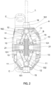
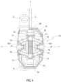
- a multi-rod disc brake contains: a brake unit including a locking structure which has two symmetrical bases, two symmetrical swing arms, two symmetrical wear resistant sleeves, and two symmetrical pistons. An accommodation chamber is defined between the two pistons to accommodate a stop disc.
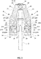
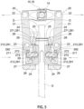
- a respective base is rotatably connected with a first rotary shaft of a respective swing arm and accommodates a respective wear resistant sleeve, the respective wear resistant sleeve movably accommodates a respective piston, an end of the respective swing arm is rotatably connected with the respective piston by a first screw bolt so that the respective swing arm actuates the respective piston to move in the respective wear resistant sleeve reciprocately; and the respective swing arm has a second rotary shaft mounted on another end thereof.
- a drive unit includes a multiple-rod structure mounted on the second rotary shaft of the respective swing arm, wherein the second rotary shaft is rotatably connected with a second screw bolt, the second screw bolt is rotatably connected with a connecting portion of a first end of a connection rod so that the respective swing arm actuates the connection rod to swing via the second rotary shaft, wherein a second end of the connection rod is rotatably connected with a respective third rotary shaft of two third rotary shafts.
- the respective third rotary shaft has a second locating orifice defined on a central section thereof, and the second locating orifice of the respective third rotary shaft is connected with a first extension of a first joining cable or a second extension of a second joining cable, wherein each of the first extension and the second extension is connected with a resilient element, the first joining cable has a first receiving orifice, and the second joining cable has a second receiving orifice, such that a brake cable is inserted through the first receiving orifice and the second receiving orifice to be fixed by a fixing element.
- the respective piston 25 has an actuation knob 28 received therein, and the actuation knob 28 has a threaded recess 281 defined on a side thereof and configured to screw with outer threads of the first screw bolt 27, wherein the first screw bolt 27 has a notch 273 defined on an end thereof, and the respective swing arm 21 has a third locating orifice 213 corresponding to the notch 273, the first screw bolt 27 further has a movable knob 272 fixed on another end thereof, and the respective swing arm 21 has a spherical trough 211 rotatably connected with the movable knob 272 of the first screw bolt 27.
- a screw nut 29 is configured to fix the respective swing arm 21 and the movable knob 272, wherein the screw nut 29 has a cavity 292 corresponding to the movable knob 272, and the screw nut 29 has an external screwing sections 291 configured to screw with inner threads 212 of the respective swing arm 21.
- the brake unit B includes a protective sleeve 30 covered thereon, and the protective sleeve 30 has a hook 31 corresponding to the brake unit B.
- the brake cable L is driven to actuate the connection rod 11 of the multiple-rod structure 10, and the respective swing arm 21 of the brake unit B is driven by the connection rod 11 to actuate the respective piston 25 to engage with the stop disc D, thus stopping the bicycle easily and quickly.
Landscapes
- Engineering & Computer Science (AREA)
- General Engineering & Computer Science (AREA)
- Mechanical Engineering (AREA)
- Braking Arrangements (AREA)
Claims (4)
- - Mehrstangen-Lamellenbremse, umfassend:eine Bremseinheit (B), wobei die Bremseinheit (B) eine Verriegelungsstruktur (20) beinhaltet, und wobei die Verriegelungsstruktur (20) zwei symmetrische Basen (24), zwei symmetrische Schwenkarme (21), zwei symmetrische verschleißfeste Hülsen (26) und zwei symmetrische Kolben (25) aufweist,wobei eine Aufnahmekammer zwischen den zwei Kolben (25) definiert ist, um eine Anschlaglamelle (D) aufzunehmen;eine entsprechende Basis (24) drehbar mit einer ersten Drehwelle (23) eines entsprechenden Schwenkarms (21) verbunden ist und eine entsprechende verschleißfeste Hülse (26) aufnimmt, wobei die entsprechende verschleißfeste Hülse (26) beweglich einen entsprechenden Kolben (25) aufnimmt, ein Ende des entsprechenden Schwenkarms (21) durch einen ersten Schraubenbolzen (27) mit dem entsprechenden Kolben (25) drehbar verbunden ist, so dass der entsprechende Schwenkarm (21) den entsprechenden Kolben (25) betätigt, um sich in der entsprechenden verschleißfesten Hülse (26) reziprok zu bewegen; und der entsprechende Schwenkarm (21) eine zweite Drehwelle (22) aufweist, die auf ein anderes Ende davon montiert ist;eine Antriebseinheit (A) eine Mehrstangenstruktur (10) beinhaltet, die auf die zweite Drehwelle (22) des entsprechenden Schwenkarms (21) montiert ist, wobei die zweite Drehwelle (22) drehbar mit einem zweiten Schraubenbolzen (131) verbunden ist, der zweite Schraubenbolzen (131) drehbar mit einem Verbindungsabschnitt (13) eines ersten Endes einer Verbindungsstange (11) verbunden ist, so dass der entsprechende Schwenkarm (21) die Verbindungsstange (11) betätigt, um mit Hilfe der zweiten Drehwelle (22) zu schwenken, wobei ein zweites Ende der Verbindungsstange (11) drehbar mit einer entsprechenden dritten Drehwelle (12) von zwei dritten Drehwellen (12) verbunden ist, die entsprechende dritte Drehwelle (12) eine zweite Positionierungsöffnung (121) aufweist, die auf einem zentralen Abschnitt davon definiert ist, und die zweite Positionierungsöffnung (121) der entsprechenden dritten Drehwelle (12) mit einer ersten Erweiterung (152) eines ersten Verbindungskabels (15) oder einer zweiten Erweiterung (162) eines zweiten Verbindungskabels (16) verbunden ist, wobei jede der ersten Erweiterung (152) und der zweiten Erweiterung (162) mit einem elastischen Element (14) verbunden ist, das erste Verbindungskabel (15) eine erste Aufnahmeöffnung (151) aufweist und das zweite Verbindungskabel (16) eine zweite Aufnahmeöffnung (161) aufweist, so dass ein Bremskabel (L) durch die erste Aufnahmeöffnung (151) und die zweite Aufnahmeöffnung (161) eingeführt wird, um durch ein Befestigungselement (L1) befestigt zu werden.
- - Mehrstangen-Lamellenbremse nach Anspruch 1, dadurch gekennzeichnet, dass im entsprechenden Kolben (25) ein Betätigungsknopf (28) aufgenommen ist und der Betätigungsknopf (28) eine gewindegeschnitten Aussparung (281) aufweist, die auf einer Seite davon definiert und konfiguriert ist, um in das Außengewinde des ersten Schraubenbolzens (27) einzuschrauben, wobei der erste Schraubenbolzen (27) eine Kerbe (273) aufweist, die auf einem Ende davon definiert ist, und der entsprechende Schwenkarm (21) eine dritte Positionierungsöffnung (213) aufweist, die der Kerbe (273) entspricht, der erste Schraubenbolzen (27) weiter einen beweglichen Knopf (272) aufweist, der an ein anderes Ende davon befestigt ist, und der entsprechende Schwenkarm (21) eine sphärische Wanne (211) aufweist, die drehbar mit dem beweglichen Knopf (272) des ersten Schraubenbolzens (27) verbunden ist.
- - Mehrstangen-Lamellenbremse nach Anspruch 2, dadurch gekennzeichnet, dass eine Schraubenmutter (29) konfiguriert ist, um den entsprechenden Schwenkarm (21) und den beweglichen Knopf (272) zu befestigen, wobei die Schraubenmutter (29) einen Hohlraum (292) aufweist, der dem beweglichen Knopf (272) entspricht, und die Schraubenmutter (29) einen externen Schraubenabschnitt (291) aufweist, der konfiguriert ist, um in die Innengewinde (212) des entsprechenden Schwenkarms (21) einzuschrauben.
- - Mehrstangen-Lamellenbremse nach Anspruch 1, dadurch gekennzeichnet, dass die Bremseinheit (B) eine Schutzhülse (30) beinhaltet, die sich darauf befindet, und die Schutzhülse (30) einen Haken (31) aufweist, der der Bremseinheit (B) entspricht.
Priority Applications (1)
| Application Number | Priority Date | Filing Date | Title |
|---|---|---|---|
| EP20177716.6A EP3919362B1 (de) | 2020-06-01 | 2020-06-01 | Mehrstangen-lamellenbremse |
Applications Claiming Priority (1)
| Application Number | Priority Date | Filing Date | Title |
|---|---|---|---|
| EP20177716.6A EP3919362B1 (de) | 2020-06-01 | 2020-06-01 | Mehrstangen-lamellenbremse |
Publications (2)
| Publication Number | Publication Date |
|---|---|
| EP3919362A1 EP3919362A1 (de) | 2021-12-08 |
| EP3919362B1 true EP3919362B1 (de) | 2023-03-15 |
Family
ID=70975727
Family Applications (1)
| Application Number | Title | Priority Date | Filing Date |
|---|---|---|---|
| EP20177716.6A Active EP3919362B1 (de) | 2020-06-01 | 2020-06-01 | Mehrstangen-lamellenbremse |
Country Status (1)
| Country | Link |
|---|---|
| EP (1) | EP3919362B1 (de) |
Family Cites Families (4)
| Publication number | Priority date | Publication date | Assignee | Title |
|---|---|---|---|---|
| DE1906698U (de) * | 1964-10-14 | 1964-12-17 | Eisenhuette Prinz Rudolph Ag | Scheibenbremse fuer schachtfoerdermaschinen. |
| US3680663A (en) * | 1969-12-23 | 1972-08-01 | Masayoshi Kine | Disk brake for a bicycle |
| GB2217408A (en) * | 1988-04-20 | 1989-10-25 | Brian Timothy Denvir | Brake mechanisms |
| JP2011102063A (ja) * | 2009-11-10 | 2011-05-26 | Bridgestone Cycle Co | 自転車用ブレーキ |
-
2020
- 2020-06-01 EP EP20177716.6A patent/EP3919362B1/de active Active
Also Published As
| Publication number | Publication date |
|---|---|
| EP3919362A1 (de) | 2021-12-08 |
Similar Documents
| Publication | Publication Date | Title |
|---|---|---|
| US2253824A (en) | Caster for application to vehicles | |
| US8905422B2 (en) | Straddle type vehicle interlocking brake system and straddle type vehicle | |
| US3776333A (en) | Bicycle brake arrangement | |
| KR100688220B1 (ko) | 차량의 연동 브레이크 장치 | |
| JPS6217346Y2 (de) | ||
| US6615955B2 (en) | Hydraulic brakes for bicycle | |
| KR102043696B1 (ko) | 자기 강화 브레이크 캘리퍼 | |
| JP3634269B2 (ja) | ディスクブレーキ | |
| WO2000001573A1 (en) | Bicycle braking system | |
| JP2011102063A (ja) | 自転車用ブレーキ | |
| JP5889764B2 (ja) | ブレーキキャリパ及びそれを備えた鞍乗型車両 | |
| TWI628373B (zh) | 鼓煞自由間隙之自動補償裝置 | |
| JP3706847B2 (ja) | 自動二輪車における制動装置 | |
| CA1039624A (en) | Auxiliary brake lever | |
| JP7444757B2 (ja) | ブレーキキャリパ装置 | |
| TWI629207B (zh) | 連動煞車系統 | |
| CA1060813A (en) | Brake construction | |
| CN210101914U (zh) | 连动刹车系统 | |
| US11021207B2 (en) | Bicycle brake | |
| US20140345981A1 (en) | Bicycle brake assembly | |
| JP2824300B2 (ja) | 自動二輪車の後輪支持構造 | |
| EP3919362A1 (de) | Mehrstangen-lamellenbremse | |
| JP3306524B2 (ja) | 自動二輪車用連動ブレーキ装置 | |
| WO2008029418A2 (en) | Power brake using wheel motion for generating an auxiliary brake force | |
| TWI697437B (zh) | 連動煞車系統 |
Legal Events
| Date | Code | Title | Description |
|---|---|---|---|
| PUAI | Public reference made under article 153(3) epc to a published international application that has entered the european phase |
Free format text: ORIGINAL CODE: 0009012 |
|
| STAA | Information on the status of an ep patent application or granted ep patent |
Free format text: STATUS: THE APPLICATION HAS BEEN PUBLISHED |
|
| AK | Designated contracting states |
Kind code of ref document: A1 Designated state(s): AL AT BE BG CH CY CZ DE DK EE ES FI FR GB GR HR HU IE IS IT LI LT LU LV MC MK MT NL NO PL PT RO RS SE SI SK SM TR |
|
| B565 | Issuance of search results under rule 164(2) epc |
Effective date: 20201029 |
|
| STAA | Information on the status of an ep patent application or granted ep patent |
Free format text: STATUS: REQUEST FOR EXAMINATION WAS MADE |
|
| 17P | Request for examination filed |
Effective date: 20220608 |
|
| RBV | Designated contracting states (corrected) |
Designated state(s): AL AT BE BG CH CY CZ DE DK EE ES FI FR GB GR HR HU IE IS IT LI LT LU LV MC MK MT NL NO PL PT RO RS SE SI SK SM TR |
|
| GRAP | Despatch of communication of intention to grant a patent |
Free format text: ORIGINAL CODE: EPIDOSNIGR1 |
|
| STAA | Information on the status of an ep patent application or granted ep patent |
Free format text: STATUS: GRANT OF PATENT IS INTENDED |
|
| RIC1 | Information provided on ipc code assigned before grant |
Ipc: F16D 65/18 20060101ALI20220914BHEP Ipc: F16D 55/22 20060101ALI20220914BHEP Ipc: B62L 1/00 20060101AFI20220914BHEP |
|
| INTG | Intention to grant announced |
Effective date: 20221005 |
|
| GRAS | Grant fee paid |
Free format text: ORIGINAL CODE: EPIDOSNIGR3 |
|
| GRAA | (expected) grant |
Free format text: ORIGINAL CODE: 0009210 |
|
| STAA | Information on the status of an ep patent application or granted ep patent |
Free format text: STATUS: THE PATENT HAS BEEN GRANTED |
|
| AK | Designated contracting states |
Kind code of ref document: B1 Designated state(s): AL AT BE BG CH CY CZ DE DK EE ES FI FR GB GR HR HU IE IS IT LI LT LU LV MC MK MT NL NO PL PT RO RS SE SI SK SM TR |
|
| REG | Reference to a national code |
Ref country code: CH Ref legal event code: EP Ref country code: GB Ref legal event code: FG4D |
|
| REG | Reference to a national code |
Ref country code: DE Ref legal event code: R096 Ref document number: 602020008810 Country of ref document: DE |
|
| REG | Reference to a national code |
Ref country code: IE Ref legal event code: FG4D |
|
| REG | Reference to a national code |
Ref country code: AT Ref legal event code: REF Ref document number: 1553870 Country of ref document: AT Kind code of ref document: T Effective date: 20230415 |
|
| REG | Reference to a national code |
Ref country code: LT Ref legal event code: MG9D |
|
| REG | Reference to a national code |
Ref country code: NL Ref legal event code: MP Effective date: 20230315 |
|
| PG25 | Lapsed in a contracting state [announced via postgrant information from national office to epo] |
Ref country code: RS Free format text: LAPSE BECAUSE OF FAILURE TO SUBMIT A TRANSLATION OF THE DESCRIPTION OR TO PAY THE FEE WITHIN THE PRESCRIBED TIME-LIMIT Effective date: 20230315 Ref country code: NO Free format text: LAPSE BECAUSE OF FAILURE TO SUBMIT A TRANSLATION OF THE DESCRIPTION OR TO PAY THE FEE WITHIN THE PRESCRIBED TIME-LIMIT Effective date: 20230615 Ref country code: LV Free format text: LAPSE BECAUSE OF FAILURE TO SUBMIT A TRANSLATION OF THE DESCRIPTION OR TO PAY THE FEE WITHIN THE PRESCRIBED TIME-LIMIT Effective date: 20230315 Ref country code: LT Free format text: LAPSE BECAUSE OF FAILURE TO SUBMIT A TRANSLATION OF THE DESCRIPTION OR TO PAY THE FEE WITHIN THE PRESCRIBED TIME-LIMIT Effective date: 20230315 Ref country code: HR Free format text: LAPSE BECAUSE OF FAILURE TO SUBMIT A TRANSLATION OF THE DESCRIPTION OR TO PAY THE FEE WITHIN THE PRESCRIBED TIME-LIMIT Effective date: 20230315 |
|
| PGFP | Annual fee paid to national office [announced via postgrant information from national office to epo] |
Ref country code: DE Payment date: 20230627 Year of fee payment: 4 |
|
| REG | Reference to a national code |
Ref country code: AT Ref legal event code: MK05 Ref document number: 1553870 Country of ref document: AT Kind code of ref document: T Effective date: 20230315 |
|
| PG25 | Lapsed in a contracting state [announced via postgrant information from national office to epo] |
Ref country code: SE Free format text: LAPSE BECAUSE OF FAILURE TO SUBMIT A TRANSLATION OF THE DESCRIPTION OR TO PAY THE FEE WITHIN THE PRESCRIBED TIME-LIMIT Effective date: 20230315 Ref country code: NL Free format text: LAPSE BECAUSE OF FAILURE TO SUBMIT A TRANSLATION OF THE DESCRIPTION OR TO PAY THE FEE WITHIN THE PRESCRIBED TIME-LIMIT Effective date: 20230315 Ref country code: FI Free format text: LAPSE BECAUSE OF FAILURE TO SUBMIT A TRANSLATION OF THE DESCRIPTION OR TO PAY THE FEE WITHIN THE PRESCRIBED TIME-LIMIT Effective date: 20230315 |
|
| PG25 | Lapsed in a contracting state [announced via postgrant information from national office to epo] |
Ref country code: SM Free format text: LAPSE BECAUSE OF FAILURE TO SUBMIT A TRANSLATION OF THE DESCRIPTION OR TO PAY THE FEE WITHIN THE PRESCRIBED TIME-LIMIT Effective date: 20230315 Ref country code: RO Free format text: LAPSE BECAUSE OF FAILURE TO SUBMIT A TRANSLATION OF THE DESCRIPTION OR TO PAY THE FEE WITHIN THE PRESCRIBED TIME-LIMIT Effective date: 20230315 Ref country code: PT Free format text: LAPSE BECAUSE OF FAILURE TO SUBMIT A TRANSLATION OF THE DESCRIPTION OR TO PAY THE FEE WITHIN THE PRESCRIBED TIME-LIMIT Effective date: 20230717 Ref country code: ES Free format text: LAPSE BECAUSE OF FAILURE TO SUBMIT A TRANSLATION OF THE DESCRIPTION OR TO PAY THE FEE WITHIN THE PRESCRIBED TIME-LIMIT Effective date: 20230315 Ref country code: EE Free format text: LAPSE BECAUSE OF FAILURE TO SUBMIT A TRANSLATION OF THE DESCRIPTION OR TO PAY THE FEE WITHIN THE PRESCRIBED TIME-LIMIT Effective date: 20230315 Ref country code: CZ Free format text: LAPSE BECAUSE OF FAILURE TO SUBMIT A TRANSLATION OF THE DESCRIPTION OR TO PAY THE FEE WITHIN THE PRESCRIBED TIME-LIMIT Effective date: 20230315 Ref country code: AT Free format text: LAPSE BECAUSE OF FAILURE TO SUBMIT A TRANSLATION OF THE DESCRIPTION OR TO PAY THE FEE WITHIN THE PRESCRIBED TIME-LIMIT Effective date: 20230315 |
|
| PG25 | Lapsed in a contracting state [announced via postgrant information from national office to epo] |
Ref country code: SK Free format text: LAPSE BECAUSE OF FAILURE TO SUBMIT A TRANSLATION OF THE DESCRIPTION OR TO PAY THE FEE WITHIN THE PRESCRIBED TIME-LIMIT Effective date: 20230315 Ref country code: PL Free format text: LAPSE BECAUSE OF FAILURE TO SUBMIT A TRANSLATION OF THE DESCRIPTION OR TO PAY THE FEE WITHIN THE PRESCRIBED TIME-LIMIT Effective date: 20230315 Ref country code: IS Free format text: LAPSE BECAUSE OF FAILURE TO SUBMIT A TRANSLATION OF THE DESCRIPTION OR TO PAY THE FEE WITHIN THE PRESCRIBED TIME-LIMIT Effective date: 20230715 |
|
| REG | Reference to a national code |
Ref country code: DE Ref legal event code: R097 Ref document number: 602020008810 Country of ref document: DE |
|
| PG25 | Lapsed in a contracting state [announced via postgrant information from national office to epo] |
Ref country code: MC Free format text: LAPSE BECAUSE OF FAILURE TO SUBMIT A TRANSLATION OF THE DESCRIPTION OR TO PAY THE FEE WITHIN THE PRESCRIBED TIME-LIMIT Effective date: 20230315 |
|
| PLBE | No opposition filed within time limit |
Free format text: ORIGINAL CODE: 0009261 |
|
| STAA | Information on the status of an ep patent application or granted ep patent |
Free format text: STATUS: NO OPPOSITION FILED WITHIN TIME LIMIT |
|
| PG25 | Lapsed in a contracting state [announced via postgrant information from national office to epo] |
Ref country code: SI Free format text: LAPSE BECAUSE OF FAILURE TO SUBMIT A TRANSLATION OF THE DESCRIPTION OR TO PAY THE FEE WITHIN THE PRESCRIBED TIME-LIMIT Effective date: 20230315 Ref country code: MC Free format text: LAPSE BECAUSE OF FAILURE TO SUBMIT A TRANSLATION OF THE DESCRIPTION OR TO PAY THE FEE WITHIN THE PRESCRIBED TIME-LIMIT Effective date: 20230315 Ref country code: DK Free format text: LAPSE BECAUSE OF FAILURE TO SUBMIT A TRANSLATION OF THE DESCRIPTION OR TO PAY THE FEE WITHIN THE PRESCRIBED TIME-LIMIT Effective date: 20230315 |
|
| REG | Reference to a national code |
Ref country code: CH Ref legal event code: PL |
|
| 26N | No opposition filed |
Effective date: 20231218 |
|
| REG | Reference to a national code |
Ref country code: BE Ref legal event code: MM Effective date: 20230630 |
|
| PG25 | Lapsed in a contracting state [announced via postgrant information from national office to epo] |
Ref country code: LU Free format text: LAPSE BECAUSE OF NON-PAYMENT OF DUE FEES Effective date: 20230601 |
|
| REG | Reference to a national code |
Ref country code: IE Ref legal event code: MM4A |
|
| PG25 | Lapsed in a contracting state [announced via postgrant information from national office to epo] |
Ref country code: LU Free format text: LAPSE BECAUSE OF NON-PAYMENT OF DUE FEES Effective date: 20230601 |
|
| PG25 | Lapsed in a contracting state [announced via postgrant information from national office to epo] |
Ref country code: IE Free format text: LAPSE BECAUSE OF NON-PAYMENT OF DUE FEES Effective date: 20230601 |
|
| PG25 | Lapsed in a contracting state [announced via postgrant information from national office to epo] |
Ref country code: IE Free format text: LAPSE BECAUSE OF NON-PAYMENT OF DUE FEES Effective date: 20230601 Ref country code: CH Free format text: LAPSE BECAUSE OF NON-PAYMENT OF DUE FEES Effective date: 20230630 |
|
| PG25 | Lapsed in a contracting state [announced via postgrant information from national office to epo] |
Ref country code: IT Free format text: LAPSE BECAUSE OF FAILURE TO SUBMIT A TRANSLATION OF THE DESCRIPTION OR TO PAY THE FEE WITHIN THE PRESCRIBED TIME-LIMIT Effective date: 20230315 Ref country code: FR Free format text: LAPSE BECAUSE OF NON-PAYMENT OF DUE FEES Effective date: 20230630 Ref country code: BE Free format text: LAPSE BECAUSE OF NON-PAYMENT OF DUE FEES Effective date: 20230630 |
|
| PG25 | Lapsed in a contracting state [announced via postgrant information from national office to epo] |
Ref country code: BG Free format text: LAPSE BECAUSE OF FAILURE TO SUBMIT A TRANSLATION OF THE DESCRIPTION OR TO PAY THE FEE WITHIN THE PRESCRIBED TIME-LIMIT Effective date: 20230315 |
|
| PG25 | Lapsed in a contracting state [announced via postgrant information from national office to epo] |
Ref country code: BG Free format text: LAPSE BECAUSE OF FAILURE TO SUBMIT A TRANSLATION OF THE DESCRIPTION OR TO PAY THE FEE WITHIN THE PRESCRIBED TIME-LIMIT Effective date: 20230315 |
|
| REG | Reference to a national code |
Ref country code: DE Ref legal event code: R119 Ref document number: 602020008810 Country of ref document: DE |
|
| GBPC | Gb: european patent ceased through non-payment of renewal fee |
Effective date: 20240601 |
|
| PG25 | Lapsed in a contracting state [announced via postgrant information from national office to epo] |
Ref country code: DE Free format text: LAPSE BECAUSE OF NON-PAYMENT OF DUE FEES Effective date: 20250101 |
|
| PG25 | Lapsed in a contracting state [announced via postgrant information from national office to epo] |
Ref country code: GB Free format text: LAPSE BECAUSE OF NON-PAYMENT OF DUE FEES Effective date: 20240601 |
|
| PG25 | Lapsed in a contracting state [announced via postgrant information from national office to epo] |
Ref country code: CY Free format text: LAPSE BECAUSE OF FAILURE TO SUBMIT A TRANSLATION OF THE DESCRIPTION OR TO PAY THE FEE WITHIN THE PRESCRIBED TIME-LIMIT; INVALID AB INITIO Effective date: 20200601 |
|
| PG25 | Lapsed in a contracting state [announced via postgrant information from national office to epo] |
Ref country code: HU Free format text: LAPSE BECAUSE OF FAILURE TO SUBMIT A TRANSLATION OF THE DESCRIPTION OR TO PAY THE FEE WITHIN THE PRESCRIBED TIME-LIMIT; INVALID AB INITIO Effective date: 20200601 |
|
| PG25 | Lapsed in a contracting state [announced via postgrant information from national office to epo] |
Ref country code: GR Free format text: LAPSE BECAUSE OF FAILURE TO SUBMIT A TRANSLATION OF THE DESCRIPTION OR TO PAY THE FEE WITHIN THE PRESCRIBED TIME-LIMIT; INVALID AB INITIO Effective date: 20200601 |
|
| PG25 | Lapsed in a contracting state [announced via postgrant information from national office to epo] |
Ref country code: TR Free format text: LAPSE BECAUSE OF FAILURE TO SUBMIT A TRANSLATION OF THE DESCRIPTION OR TO PAY THE FEE WITHIN THE PRESCRIBED TIME-LIMIT Effective date: 20230315 |