EP3919680A1 - Chaîne de production de moulage de pâte à papier et procédé de traitement associé - Google Patents
Chaîne de production de moulage de pâte à papier et procédé de traitement associé Download PDFInfo
- Publication number
- EP3919680A1 EP3919680A1 EP19913805.8A EP19913805A EP3919680A1 EP 3919680 A1 EP3919680 A1 EP 3919680A1 EP 19913805 A EP19913805 A EP 19913805A EP 3919680 A1 EP3919680 A1 EP 3919680A1
- Authority
- EP
- European Patent Office
- Prior art keywords
- mold
- pulp
- wet blank
- blank transfer
- matching cavity
- Prior art date
- Legal status (The legal status is an assumption and is not a legal conclusion. Google has not performed a legal analysis and makes no representation as to the accuracy of the status listed.)
- Pending
Links
Images



Classifications
-
- D—TEXTILES; PAPER
- D21—PAPER-MAKING; PRODUCTION OF CELLULOSE
- D21J—FIBREBOARD; MANUFACTURE OF ARTICLES FROM CELLULOSIC FIBROUS SUSPENSIONS OR FROM PAPIER-MACHE
- D21J3/00—Manufacture of articles by pressing wet fibre pulp, or papier-mâché, between moulds
-
- D—TEXTILES; PAPER
- D21—PAPER-MAKING; PRODUCTION OF CELLULOSE
- D21F—PAPER-MAKING MACHINES; METHODS OF PRODUCING PAPER THEREON
- D21F7/00—Other details of machines for making continuous webs of paper
- D21F7/02—Mechanical driving arrangements
-
- D—TEXTILES; PAPER
- D21—PAPER-MAKING; PRODUCTION OF CELLULOSE
- D21J—FIBREBOARD; MANUFACTURE OF ARTICLES FROM CELLULOSIC FIBROUS SUSPENSIONS OR FROM PAPIER-MACHE
- D21J3/00—Manufacture of articles by pressing wet fibre pulp, or papier-mâché, between moulds
- D21J3/12—Manufacture of articles by pressing wet fibre pulp, or papier-mâché, between moulds of sheets; of diaphragms
-
- D—TEXTILES; PAPER
- D21—PAPER-MAKING; PRODUCTION OF CELLULOSE
- D21J—FIBREBOARD; MANUFACTURE OF ARTICLES FROM CELLULOSIC FIBROUS SUSPENSIONS OR FROM PAPIER-MACHE
- D21J7/00—Manufacture of hollow articles from fibre suspensions or papier-mâché by deposition of fibres in or on a wire-net mould
-
- D—TEXTILES; PAPER
- D21—PAPER-MAKING; PRODUCTION OF CELLULOSE
- D21F—PAPER-MAKING MACHINES; METHODS OF PRODUCING PAPER THEREON
- D21F13/00—Making discontinuous sheets of paper, pulpboard or cardboard, or of wet web, for fibreboard production
- D21F13/10—Making discontinuous sheets of paper, pulpboard or cardboard, or of wet web, for fibreboard production using board presses
- D21F13/12—Platen presses
-
- D—TEXTILES; PAPER
- D21—PAPER-MAKING; PRODUCTION OF CELLULOSE
- D21F—PAPER-MAKING MACHINES; METHODS OF PRODUCING PAPER THEREON
- D21F2/00—Transferring continuous webs from wet ends to press sections
-
- D—TEXTILES; PAPER
- D21—PAPER-MAKING; PRODUCTION OF CELLULOSE
- D21F—PAPER-MAKING MACHINES; METHODS OF PRODUCING PAPER THEREON
- D21F3/00—Press section of machines for making continuous webs of paper
- D21F3/02—Wet presses
- D21F3/0272—Wet presses in combination with suction or blowing devices
Definitions
- the invention relates generally to the technical field of pulp molding machinery, in particular to a pulp molding production line and a processing method thereof.
- the existing pulp molding production manipulator is generally equipped with a transfer mold jig, which is used to transfer the pulp molding wet blank to the mold or obtain and release the pressed products. Since only one action can be performed at any given time, and the wet blank transfer and product acquisition and release cannot be completed at the same time, resulting in low production efficiency.
- Chinese patent application number CN 201320735610.7 discloses a handling manipulator for pulp molding machine.
- the manipulator has three degrees of freedom and can move in X, Y and Z directions.
- the movement (lateral movement) in the X direction is realized by two rod-less cylinders and linear guide rails, which can accurately realize the positioning in three states.
- the Y-direction movement (translation) and Z-direction movement (vertical lifting) are realized by motor and screw rods, which can realize accurate positioning at any position within the travel range.
- the grasping and lowering of steel pallets are realized by turning on and off electromagnets.
- the manipulator can directly catch the goods produced by the pulp molding machine from the mold with pallets, and then place them on the trolley in sequence for unified drying.
- the manipulator is simple in structure, easy to manufacture, low in cost and stable in performance, which can replace manpower and save labor and production cost.
- the purpose of the invention is to provide a paper pulp molding production line and a processing method which can greatly improve production efficiency for the above problems.
- a pulp molding production line comprises at least one molding machine, a pulp molding manipulator and at least one press, wherein the molding machine, the pulp molding manipulator and the press are arranged in sequence, and a transfer device is installed on the pulp molding manipulator, which takes and transfers wet pulp blank products molded by the molding machine to the press, and takes, transfers and releases the pulp products molded by the press, a wet blank transfer mold is internally provided with an airtight air chamber inside, a front face of the wet blank transfer mold is provided with at least one recessed matching cavity which can be sheathed on the outside of a pulp wet blank container and is recessed towards the airtight air chamber, and the recessed matching cavity matches the pulp wet blank container; several small communicating holes for communication between the recessed matching cavity and the airtight air chamber are respectively provided in an inner wall of each recessed matching cavity and at the bottom of the recessed matching cavity, the small communicating holes provided in the inner wall of the recessed matching cavity are circumferential
- each circle is respectively formed by several circumferentially evenly distributed small communicating holes.
- the center of the bottom of the recessed matching cavity is provided with central holes for communicating the recessed matching cavity with the airtight air chamber.
- the wet blank transfer mold comprises a main mold plate with a cavity on the back, wherein the cavity has an opening communicated with the outside, and several recessed matching cavities distributed in an array are provided on the front face of the main mold plate; several small communicating holes for communication between the recessed matching cavity and the airtight air chamber are respectively provided in the inner wall of each recessed matching cavity and at the bottom of the recessed matching cavity, the inner bottom part of the cavity is provided with several inner convex parts corresponding to the recessed matching cavities one by one, and the small communicating holes penetrate through the inner convex parts; the wet blank transfer mold also includes a closing mold plate for closing the cavity opening, and the airtight air chamber is formed between the main mold plate and the closing mold plate.
- the bottom of the chamber is provided with a reinforcing supporting structure contacting with a surface of the closing mold plate near to the chamber.
- the reinforcing supporting structure comprises several first reinforcing supporting bulges with uniform transverse spacing and several second reinforcing supporting bulges with uniform longitudinal spacing, wherein the first reinforcing supporting bulges are located on the same straight line and at the transverse center of the chamber, the second reinforcing supporting bulges are located on the same straight line and at the longitudinal center of the chamber, the first reinforcing supporting bulges and the second reinforcing supporting bulges are in a cross shape, and one end of the first reinforcing supporting bulges far away from the bottom of the chamber abut against a surface of the closing mold plate near to the chamber, and one end of the second reinforcing supporting bulges far away from the bottom of the chamber abut against a surface of the closing mold plate near to the chamber.
- a first supporting plane is provided at one end of each first reinforcing supporting bulge abutting against the closing mold plate, and a second supporting plane is provided at one end of each second reinforcing supporting bulge abutting against the closing mold plate, and the first supporting plane and the second supporting plane are located in the same horizontal plane.
- the inner wall of the chamber is provided with several arc-shaped concave surfaces which are connected in sequence, and the outermost inner convex part of the inner convex parts corresponds to the arc-shaped concave surface one by one.
- the guiding mechanism comprises several guide posts which are parallel to each other and one end of which is fixed on the back of the wet blank transfer mold, several guide sleeve fixing holes and guide sleeves fixed on the guide sleeve fixing holes are provided on the moving frame, and the guide sleeves are set on the guide posts one by one, and the guide sleeves are in sliding connection with the guide posts.
- recessed matching cavities are taken as one area, and four such areas are provided on the front face of the wet blank transfer mold.
- first reinforcing supporting bulges are connected by first arc-shaped connecting ribs
- second reinforcing supporting bulges are located outside the middle-most first reinforcing supporting bulge
- each second reinforcing supporting bulge is connected with the middle-most first reinforcing supporting bulge by a second arc-shaped connecting rib.
- the main mold plate and the closing mold plate are connected by a detachable connection structure.
- the detachable connection structure comprises an annular shoulder provided in the circumferential direction of the main mold plate, wherein the thickness of the annular shoulder is smaller than that of the main mold plate, the back surface of the main mold plate is flush with that of the annular shoulder, each side edge of the closing mold plate is respectively pierced with a locking bolt which penetrates through a nail passing hole of the annular shoulder and is sheathed with a locking nut, and the lock nut is in contact with the front face of the annular shoulder.
- the front face of the annular shoulder is provided with a yielding notch communicated with the nail passing hole, and the locking nut is positioned in the yielding notch and contacts with the bottom surface of the yielding notch.
- the molding machine is of the prior art.
- the press includes a lower base, four vertical guide posts connected to the top of the lower base, an upper mold holder connected to the upper ends of the four vertical guide posts, and also a movable lower mold holder movably connected with the vertical guide posts; the movable lower mold holder is connected with the master cylinder of the press and drives the movable lower mold holder to lift axially along the vertical guide posts, which is characterized in that the press also includes an auxiliary frame located between the movable lower mold holder seat and the upper mold holder, and the auxiliary frame is connected with the lifting drive mechanism.
- the auxiliary frame is sleeved on the transfer device, and the auxiliary frame assists the transfer device to lift and fall under the action of external force.
- the auxiliary frame comprises an auxiliary push plate, the edges of which are provided with four guide round holes for the vertical guide posts to penetrate one by one, and the auxiliary push plate is provided with a polygonal central through hole, and the guide round holes are located at the periphery of the polygonal central through hole.
- the polygonal central through hole is an octagonal through hole.
- the periphery of the auxiliary push plate is provided with outer sides corresponding to the walls of the octagonal through holes one by one, and the outer sides form an octagon.
- the reinforcing structure comprises transverse reinforcing ribs connected between the two cantilever bosses and connected with the outer wall of the auxiliary push plate, longitudinal reinforcing ribs are arranged in the middle of the transverse reinforcing ribs and the inner end of the longitudinal reinforcing ribs are connected with the outer wall of the auxiliary push plate.
- the upper orifice and the lower orifice of the octagonal through hole are respectively provided with the first circular chamfers, and the two sides of each outer side are respectively provided with the second circular chamfers.
- the lifting driving mechanism comprises two fixed frame respectively fixed on the top part of the lower base, a first cylinder is fixed in each fixed frame body, and the telescopic rods of the first cylinders face upwards and are connected to the middle part of the lower surface of the transverse reinforcing ribs one by one.
- the first cylinder can be replaced by an oil cylinder or a linear motor.
- the fixing frame body is rectangular and vertically fixed, with a first strip hole in its upper central area and a second strip hole in its lower central area.
- the telescopic rod of the first cylinder penetrates through the first strip hole and a fixing plate is sleeved on the upper end of the first cylinder.
- the fixing plate is located on the upper surface of the orifice of the first strip hole, and several first bolts penetrate through the fixing plate, are connected through threads with the screw holes at the top of the fixing frame body, and the lower end of the first cylinder penetrates through the second strip hole.
- Reference designations in the figures are as follows: airtight air chamber 0, wet blank transfer mold 10, recessed matching cavity 101, small communicating holes 102, small central hole 103, main mold plate 104, cavity 1041, inner convex part 1042, first reinforcing supporting bulge 1043, second reinforcing supporting bulge 1044, first supporting plane 1045, second supporting plane 1046, arc concave surface 1047, first arc connecting rib 1048, second arc connecting rib 1049, closing mold plate 105, annular shoulder 106, yielding notch 107, guiding mechanism 20, guide post 201, guide sleeve 202, moving frame 30, driver 40, vacuum cup 50, vacuum-pumping system 60, pulp molding manipulator 3a, press 2a, transfer device Q, auxiliary frame N, auxiliary push plate 1, polygonal central through hole 11, first circular chamfer 111, second circular chamfer 112, cantilever lug boss 12, circular guide hole 121, reinforcing structure 13, transverse reinforcing rib 131, longitudinal reinfor
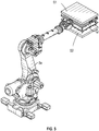
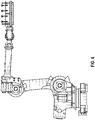
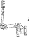
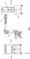
- a pulp molding production line comprises at least one molding machine S, a pulp molding manipulator 3a and at least one press 2a, wherein the molding machine, the pulp molding manipulator and the press are arranged in sequence, and a transfer device Q is installed on the pulp molding manipulator, and the transfer device acquires and transfers wet pulp products molded by the molding machine to the press, and acquires, transfers and releases pulp products molded by the press.
- forming machines S there are several forming machines S; in the case of two machines, they are arranged at intervals, in the case of three, they are arranged in a row or triangle or arch shape, and in the case of four, they are arranged in a row or arch shape.
- the arrangement pattern of the press 2a is consistent with that of the molding machine S.
- a transfer device comprises a wet blank transfer mold 10 internally provided with an airtight air chamber 0, and at least one recessed matching cavity 101 which can be sheathed outside a pulp wet blank container and recessed toward the airtight air chamber 0 is provided on the front face of the wet blank transfer mold 10, and the recessed matching cavity 101 matches the pulp wet blank container.
- This structure can enlarge the contact surface with the wet blank container, and improve the efficiency and stability of material taking.
- each recessed matching cavity 101 and the bottom of each recessed matching cavity 101 On an inner wall of each recessed matching cavity 101 and the bottom of each recessed matching cavity 101, several small communicating holes 102 are respectively used for communicating the recessed matching cavities with the airtight air chamber 0, the small communicating holes 102 provided on the inner wall of the recessed matching cavity 101 are circumferentially uniformly distributed and form at least one circle in an encircling manner.
- the small communicating holes 102 provided at the bottom of the recessed matching cavity 101 are circumferentially uniformly distributed and form at least one circle in an encircling manner.
- each circle is formed by several small communicating holes 102 evenly distributed around the circumference.
- the center of the bottom of the recessed matching cavity 101 is provided with a small central hole 103 for communicating the recessed matching cavity 101 with the airtight air chamber 0.
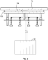
- a moving frame 30 parallel to the wet blank transfer mold 10 is connected to the back face of the wet blank transfer mold 10 via a guiding mechanism 20, wherein the guiding mechanism 20 includes several guide posts 201 which are parallel to each other and one end of which is fixed on the back face of the wet blank transfer mold 10, the moving frame 30 is provided with several guide sleeve fixing holes and guide sleeves 202 fixed on the guide sleeve fixing holes, the guide sleeves 202 are set on the guide posts 201, and the guide sleeves 202 are in sliding connection with the guide posts 201.
- the coordination of guide sleeves 202 and guide posts 201 can further improve the smoothness and stability of lifting and lowering.
- a driver 40 is connected between the back surface of the wet blank transfer mold 10 and the moving frame 30, and drives the moving frame 30 to move relative to the wet blank transfer mold 10.
- the driver 40 is any one of an air cylinder, an oil cylinder and a linear motor.
- the moving frame 30 is provided with several evenly spaced vacuum cups 50, and the vacuum cups 50 and the airtight air chamber 0 are respectively connected with a vacuum-pumping system 60.
- the vacuum-pumping system 60 includes a vacuum pumping pipeline and vacuum pumping equipment connected with the vacuum pumping pipeline, and the vacuum pumping equipment is a commercially available product.
- the air in the airtight air chamber 0 is forced to be sucked out, and at this time, the wet blank container can be sucked and transferred into the forming mold by using the communicating hole 102 and the center hole 103, i.e., into the upper mold or the lower mold of the forming mold, and at the same time, the vacuum cup 50 can be lifted or lowered by the action of the driver, so as to suck the pulp molded products formed by the molding mold, and can complete the transfer and taking and placing actions at the same time, thus greatly improving the production and processing efficiency.
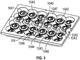
- the wet blank transfer mold 10 of this embodiment includes a main mold plate 104 with a cavity 1041 on the back face, the cavity 1041 has an opening communicating with the outside, and several recessed matching cavities 101 distributed in an array are provided on the front face of the main mold plate 104.
- Several small communicating holes 102 for communication between the recessed matching cavity 101 and the airtight air chamber 0 are respectively provided in the inner wall of each recessed matching cavity 101 and at the bottom of the recessed matching cavity 101.
- the inner bottom of the chamber 1041 is provided with several inner convex parts 1042 corresponding to the recessed matching cavities 101 one by one, and the small communicating holes 102 penetrate through the inner convex parts 1042.
- the wet blank transfer mold 10 also includes a closing mold plate 105 for closing the opening of the cavity 1041, and the airtight air chamber 0 is formed between the main mold plate 104 and the closing mold plate 105.
- the inner convex part 1042 corresponds to the recessed matching cavity 101, so as to facilitate the development of the mold and reduce the manufacturing difficulty.
- the wet blank is not limited to the upper mold S1, and the product is not limited to the lower mold S2. That is to say, the wet blank can be transferred to the upper mold or the lower mold, and the corresponding product can be taken out from the lower mold or the upper mold.
- This objective can be achieved by the same device, which can be installed positively or reversely, or turned over by the end joint of the manipulator; Wet blank transfer or product transfer is performed through vacuum suction.
- There is an airtight air chamber in the wet blank mold which is connected to the vacuum pipeline, and the vacuum cup is connected to the vacuum pipeline. For releasing the wet blank or product, just convert vacuum operation into blowing operation.
- the bottom of the cavity 1041 is provided with a reinforcing supporting structure which is in contact with a surface of the closing mold plate 105 near the cavity 1041.
- the reinforcing supporting structure of this embodiment includes several first reinforcing supporting bulges 1043 with uniform transverse spacing and several second reinforcing supporting bulges 1044 with uniform longitudinal spacing.
- the first reinforcing supporting bulges 1043 and the second reinforcing supporting bulges 1044 are located on the same line and at the lateral center of the chamber 1041, forming a cross shape.
- the end of the first reinforcing supporting bulge 1043 which is away from the bottom of the chamber 1041 abuts against a surface of the closing mold plate 105 near the chamber 1041, and the end of the second reinforcing supporting bulge 1044 which is away from the bottom of the chamber 1041 abuts against a surface of the closing mold plate 105 near the chamber 1041.
- the first reinforcing supporting bulges 1043 and the second reinforcing supporting bulges 1044 can further improve the structural strength and prolong the service life of the closing mold plate 105.
- a first supporting plane 1045 is provided at one end of each first reinforcing supporting bulge 1043 abutting against the closing mold plate 105, and a second supporting plane 1046 is provided at one end of each second reinforcing supporting bulge 1044 abutting against the closing mold plate 105, which are located in the same horizontal plane.
- the supporting plane can improve the stability and reliability of contact.
- the inner wall of the chamber 1041 is provided with several arc-shaped concave surfaces 1047 connected in sequence, and the outermost inner convex part 1042 of the inner convex parts 1042 corresponds to the arc-shaped concave surfaces 1047 one by one.
- recessed matching cavities 101 of this embodiment are taken as one area, and the front face of the wet blank transfer mold 10 is provided with four of such areas.
- first reinforcing supporting bulges 1043 are connected by first arc-shaped connecting ribs 1048
- second-reinforcing supporting bulges 1044 are located outside the middle-most first reinforcing supporting bulge 1043
- each second reinforcing supporting bulge 1044 is connected with the middle-most first reinforcing supporting bulge 1043 by second arc-shaped connecting rib 1049.
- the main mold plate 104 and the closing mold plate 105 in this embodiment are connected by a detachable connection structure.
- the detachable connection structure includes an annular shoulder 106 provided in the circumferential direction of the main mold plate 104, the thickness of which is smaller than that of the main mold plate 104, and the back of the main mold plate 104 is flush with the back of the annular shoulder.
- Each side of the closing mold plate 105 is pierced with a locking bolt, which penetrates through the nail passing hole of the annular shoulder, and a locking nut is sheathed on the locking bolt, which is in contact with the front face of the annular shoulder.
- the front face of the annular shoulder is provided with a yielding notch 107 communicating with the nail passing hole, and the locking nut is located in the yielding notch and contacts with the bottom surface of the yielding notch.
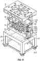
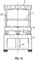
- the press 2a comprises a lower base 2, four vertical guide posts 21 connected to the top of the lower base 2, an upper mold holder 3 connected to the upper ends of the four vertical guide posts 21, and a movable lower mold holder 4 positioned directly below the upper mold holder 3 and movably connected with the vertical guide posts 21.
- the movable lower mold holder 4 is connected with the press master cylinder 41, which drives the movable lower mold holder 4 to move up and down axially along the vertical guide posts 21.
- the press master cylinder 41 is fixed at the center of the lower base 2, and the telescopic rod of the press master cylinder 41 is connected facing upward with the center of the lower surface of the movable lower mold holder 4.
- the master cylinder 41 of the press drives the movable lower mold holder 4 to move up and down, which can improve the stability and reliability of lifting and lowering in cooperation with the vertical guide posts 21.
- a transfer device Q is connected to the pulp molding manipulator 3a, and the transfer device Q is the above-mentioned "a transfer device applied to a pulp molding manipulator".
- the press 2a is provided with an auxiliary frame N located between the movable lower mold holder 4 and the upper mold holder 3, and the press is provided with a lifting drive mechanism 5 for driving the auxiliary frame to lift and lower in the vertical direction.
- the pulp molding manipulator forces the transfer device to extend into between the movable lower mold holder and the upper mold holder, and the lifting drive mechanism drives the auxiliary frame to contact with and forces the transfer device to move vertically upward or downward.
- the auxiliary frame N includes a horizontally provided auxiliary push plate 1, which is made of metal material or non-metal material, and any material that can meet the strength requirements can be adopted in this embodiment.
- the auxiliary push plate 1 is provided with a polygonal central through-hole 11.
- the polygonal central through-hole 11 in this embodiment is an octagonal through-hole, which can form the placement of the mold jig and contact with the mold jig, and force the mold jig to rise and fall under the action of the lifting drive mechanism.
- the periphery of the auxiliary push plate 1 is provided with outer sides corresponding to the hole walls of the octagonal through hole one by one, and the outer sides form an octagon.
- the upper and lower openings of the octagonal through-hole are respectively provided with first circular chamfers 111, and the two sides of each outer side are respectively provided with second circular chamfers 112.
- Circular chamfering can avoid damaging mold jig or pulp products.
- Each cantilever boss 12 is respectively provided with a vertically provided guide circular hole 121, and a reinforcing structure 13 is provided between the two cantilever bosses 12 provided at the same end.
- the reinforcing structure 13 includes transverse reinforcing ribs 131 connected between the two cantilever bosses 12 and connected with the outer wall of the auxiliary push plate 1, wherein longitudinal reinforcing ribs 132 are provided in the middle of the transverse reinforcing ribs 131 and the inner ends of the longitudinal reinforcing ribs 132 are connected with the outer wall of the auxiliary push plate 1.
- auxiliary push plate 1 cantilever bosses 12, transverse reinforcing ribs 131 and longitudinal reinforcing ribs 132 are integrally formed, which can improve the overall structural strength.
- the lifting driving mechanism 5 drives the auxiliary push plate 1 to rise and fall between the movable lower mold holder 4 and the upper mold holder 3.
- the mold jig connected to the manipulator can be forced to rise or fall. That is, auxiliary push plate 1 is sheathed on a wet blank transfer mold 10 and connected to an annular 106 shoulder, so to enhance the stability of the pushing force, and the manipulator does not need to perform upward or downward thrust action, thereby ensuring the working reliability of the manipulator, and also prolonging the service life of the manipulator, so that the production can be carried out continuously and smoothly, which is more in line with the production requirements of enterprises.
- the lifting drive mechanism 5 includes two fixed frames 51 respectively fixed on the top of the lower base 2, and the first cylinders 52 are respectively fixed in each fixed frame body 51, and the telescopic rods of the first cylinders 52 facing upwards and are connected to the middle of the lower surface of the transverse reinforcing ribs 131 one by one.
- the fixed frame body 51 is a rectangular frame and is vertically fixed.
- the upper central area of the fixed frame body 51 is provided with a first strip hole 511
- the lower central area of the fixed frame body 51 is provided with a second strip hole 512.
- the telescopic rod of the first cylinder 52 penetrates through the first strip hole 511 and a fixing plate 513 is sheathed on the upper end of the cylinder body of the first cylinder 52.
- the fixing plate 513 is located on the upper surface of the opening of the first strip hole 511, and several bolts 514 penetrate through the fixing plate 513.
- the bolts 514 are connected through threading with the top threaded hole of the fixing frame body 51, and the lower end of the first cylinder 52 penetrates through the second strip hole 512.
- strip holes The design of strip holes is to facilitate position movement and adjustment.
- the movable lower mold holder 4 moves upward under the driving of the press master cylinder 41, and then the lower pulp product mold on the movable lower mold holder 4 and the upper pulp product mold on the upper mold holder 3 cooperate with each other to process pulp products.
- the manipulator at this time needs to obtain pulp products.
- the pulp products are obtained and released to the next station by installing a mold jig on the manipulator.
- the auxiliary push plate 1 is forced to rise or fall in the vertical direction by the lifting drive mechanism 5, and the auxiliary push plate 1 is sheathed on the mold jig, which can assist the rising or falling of the mold jig, thereby eliminating the alarm caused by the upward or downward movement of the mold jig by using the manipulator.
- the working principle of this embodiment is as follows:
- the forming machine S transfers the pulp to the press through the transfer device on the manipulator after forming and extruding, that is, the wet blank transfer mold acquires the pulp wet blank products formed by the forming machine S, and at the same time, after the transfer device of the manipulator enters the press and stops at the set position (i.e., between the upper mold and the lower mold), there are two schemes:
- the processing method of the pulp molded product comprises the following steps:
- the processing method of the pulp molded product comprises the following steps:
Landscapes
- Engineering & Computer Science (AREA)
- Manufacturing & Machinery (AREA)
- Mechanical Engineering (AREA)
- Paper (AREA)
- Making Paper Articles (AREA)
- Moulds For Moulding Plastics Or The Like (AREA)
- Specific Conveyance Elements (AREA)
- Mounting, Exchange, And Manufacturing Of Dies (AREA)
Applications Claiming Priority (2)
| Application Number | Priority Date | Filing Date | Title |
|---|---|---|---|
| CN201910098112.8A CN110219210B (zh) | 2019-01-31 | 2019-01-31 | 一种纸浆模塑生产线及加工方法 |
| PCT/CN2019/128104 WO2020155948A1 (fr) | 2019-01-31 | 2019-12-24 | Chaîne de production de moulage de pâte à papier et procédé de traitement associé |
Publications (2)
| Publication Number | Publication Date |
|---|---|
| EP3919680A1 true EP3919680A1 (fr) | 2021-12-08 |
| EP3919680A4 EP3919680A4 (fr) | 2022-10-26 |
Family
ID=67822312
Family Applications (1)
| Application Number | Title | Priority Date | Filing Date |
|---|---|---|---|
| EP19913805.8A Pending EP3919680A4 (fr) | 2019-01-31 | 2019-12-24 | Chaîne de production de moulage de pâte à papier et procédé de traitement associé |
Country Status (9)
| Country | Link |
|---|---|
| US (3) | US11560673B2 (fr) |
| EP (1) | EP3919680A4 (fr) |
| JP (1) | JP2022518609A (fr) |
| KR (1) | KR20210144667A (fr) |
| CN (1) | CN110219210B (fr) |
| AU (1) | AU2019427078B2 (fr) |
| CA (1) | CA3128270A1 (fr) |
| MX (1) | MX2021009213A (fr) |
| WO (1) | WO2020155948A1 (fr) |
Families Citing this family (30)
| Publication number | Priority date | Publication date | Assignee | Title |
|---|---|---|---|---|
| CN110216710B (zh) | 2019-01-31 | 2025-02-21 | 浙江舒康科技有限公司 | 一种应用于纸浆模塑机械手的转移装置及生产线 |
| CN110219210B (zh) * | 2019-01-31 | 2024-02-27 | 浙江舒康科技有限公司 | 一种纸浆模塑生产线及加工方法 |
| CN112941973B (zh) * | 2019-12-10 | 2024-06-21 | 浙江舒康科技有限公司 | 翻转吸浆机器人转移成型机及成型方法 |
| CN110952385A (zh) * | 2019-12-31 | 2020-04-03 | 二十五度加(广州)科技发展有限公司 | 一种可降解甘蔗纸浆餐具成型机 |
| CN111287022B (zh) * | 2020-03-26 | 2025-05-13 | 浙江舒康科技有限公司 | 一种带加热和切边功能的纸制品加工生产线 |
| CN111254754B (zh) * | 2020-03-26 | 2025-05-13 | 浙江舒康科技有限公司 | 纸制品生产用倒吸浆式生产线 |
| CN111395051B (zh) * | 2020-03-26 | 2021-10-26 | 浙江舒康科技有限公司 | 一种纸制品容器加工方法 |
| DE102020109686A1 (de) * | 2020-04-07 | 2021-10-07 | Kiefel Gmbh | Deckel mit Unterschneidung auf der Grundlage von Naturfasern |
| CN111778777B (zh) * | 2020-07-25 | 2024-07-19 | 浙江舒康科技有限公司 | 一种纸制品热压成型机 |
| CN113026433B (zh) * | 2021-01-29 | 2023-05-26 | 杭州英飞创机械设备有限公司 | 一种硅酸铝纤维堵套的自动化生产设备 |
| CN113235323B (zh) * | 2021-04-20 | 2022-12-09 | 东莞市凯成环保科技有限公司 | 一种全纸塑“零度”拔模生产工艺 |
| CN113737574B (zh) * | 2021-07-20 | 2023-08-29 | 东莞三润田智能科技有限公司 | 纸模带网转移方法 |
| CN113605151B (zh) * | 2021-07-20 | 2025-04-11 | 东莞三润田智能科技有限公司 | 关节机器人带网转移式纸模生产线 |
| CN113818287A (zh) * | 2021-07-20 | 2021-12-21 | 东莞三润田智能科技有限公司 | 龙门机械手带网转移式纸模成型线 |
| CN113605150B (zh) * | 2021-07-20 | 2023-08-29 | 东莞三润田智能科技有限公司 | 关节机器人带网转移式纸模生产方法 |
| CN113584951A (zh) * | 2021-07-26 | 2021-11-02 | 广东卡雷尔环保科技有限公司 | 一种网转式纸模生产设备 |
| CN113846395B (zh) * | 2021-09-15 | 2022-08-23 | 徐州市全鑫毛制品有限公司 | 一种能够筛选包装的毛纺加工用推毛装置 |
| CN114059392A (zh) * | 2021-09-30 | 2022-02-18 | 广东科捷龙机器人有限公司 | 多层纸模快速定型工艺 |
| CN113910687A (zh) * | 2021-09-30 | 2022-01-11 | 广东科捷龙机器人有限公司 | 纸模多层快速定型机构 |
| CN114032708B (zh) * | 2021-12-06 | 2023-11-14 | 浙江迪凡特环保科技有限公司 | 一种半干压植物纤维模塑成型机及成型方法 |
| WO2023102828A1 (fr) * | 2021-12-09 | 2023-06-15 | 巢邕 | Dispositif de moulage composite de fibres de pâte à papier |
| TWI795213B (zh) * | 2022-02-17 | 2023-03-01 | 邱聖峯 | 自動化紙漿模塑成型方法 |
| US20240253868A1 (en) * | 2022-03-23 | 2024-08-01 | Foshan City Meiwanbang Technology Co., Ltd. | Forming Structure for Internal Snap Ring of Pulp Molded Cup Lid |
| CN116794055A (zh) * | 2022-06-30 | 2023-09-22 | 永发(河南)模塑科技发展有限公司 | 一种纸浆模塑产品外观瑕疵自动检验系统 |
| CN115229586B (zh) * | 2022-08-11 | 2024-03-19 | 北京泰和磁记录制品有限公司 | 一种刷卡磁头夹具的自动输运装置以及平磨装置 |
| CN115890586B (zh) * | 2022-09-30 | 2025-06-20 | 南京康尼机电股份有限公司 | 一种辅助装拆列车门扇的机械装置 |
| CN115450072A (zh) * | 2022-10-27 | 2022-12-09 | 广东瀚迪科技有限公司 | 吸浆成型模具组件 |
| GB2631421B (en) * | 2023-06-29 | 2025-09-03 | Pulpex Ltd | Transfer device |
| CN118322427B (zh) * | 2024-06-12 | 2024-08-09 | 深圳市新劲力机械有限公司 | 一种硫化机进料机械手 |
| CN118653330B (zh) * | 2024-08-21 | 2024-11-05 | 合肥朗胜新材料有限公司 | 一种纸塑产品用湿压设备 |
Family Cites Families (76)
| Publication number | Priority date | Publication date | Assignee | Title |
|---|---|---|---|---|
| US1163005A (en) | 1914-04-15 | 1915-12-07 | William D Hall | Jar-closure. |
| US2879935A (en) | 1957-03-13 | 1959-03-31 | Maryland Cup Company | Resilient paper covers for containers and method of manufacture |
| US3065875A (en) | 1960-02-19 | 1962-11-27 | Continental Can Co | Plastic snap-on reclosure cover |
| CN87206542U (zh) | 1987-04-16 | 1988-09-28 | 赵红 | 手开瓶盖 |
| CN2035341U (zh) | 1988-06-24 | 1989-04-05 | 陆国强 | 卡口瓶易开复用盖 |
| CN2055127U (zh) | 1989-08-03 | 1990-03-28 | 南昌市罐头啤酒厂 | 滴塑瓶盖 |
| US5626229A (en) | 1990-11-05 | 1997-05-06 | Intepac Technologies Inc. | Gas-containing product supporting structure and package |
| CN2138642Y (zh) | 1992-09-24 | 1993-07-21 | 阎义浩 | 压盖模 |
| US5515976A (en) | 1995-08-18 | 1996-05-14 | Plastofilm Industries, Inc. | Packaging for fragile articles within container |
| IT1287222B1 (it) | 1996-03-25 | 1998-08-04 | Stelplast Di Vidale Stelvio & | Tappo perfezionato per bottiglie atto ad esser impiegato nella prima fase di lavorazione di spumanti col metodo champenois e per la |
| US5678692A (en) | 1996-05-15 | 1997-10-21 | Fibreform Containers, Inc. | Corner protector |
| JP3173432B2 (ja) | 1997-09-08 | 2001-06-04 | ティアック株式会社 | 緩衝材 |
| WO1999042660A1 (fr) | 1998-02-23 | 1999-08-26 | Kao Corporation | Procede de fabrication de produits formes par moulage de pulpe agglomeree |
| US6576089B1 (en) | 1999-03-26 | 2003-06-10 | Kao Corporation | Paper making mold for pulp mold molding production and method and device for producing pulp mold molding |
| US6082543A (en) | 1999-12-06 | 2000-07-04 | Polyform A.G.P. Inc. | Packing protector |
| JP3512699B2 (ja) | 2000-03-06 | 2004-03-31 | 花王株式会社 | パルプモールド成形体の製造方法 |
| KR100536031B1 (ko) | 2000-04-11 | 2005-12-14 | 가오가부시끼가이샤 | 펄프 몰드 성형체의 제조방법 |
| JP3477425B2 (ja) | 2000-04-18 | 2003-12-10 | 榮佳科技股▲分▼有限公司 | パルプ成型離型機 |
| US6918997B2 (en) | 2000-04-18 | 2005-07-19 | Kao Corporation | Method of producing pulp moldings |
| CN2439458Y (zh) | 2000-07-28 | 2001-07-18 | 罗济藏 | 旋转式纸浆成形机新结构 |
| JP4039879B2 (ja) | 2001-04-06 | 2008-01-30 | 花王株式会社 | フランジ付き抄造成形体の製造方法 |
| CN1265057C (zh) | 2001-08-03 | 2006-07-19 | 花王株式会社 | 纸浆模成型体、其制造方法和制造装置 |
| US6716319B2 (en) | 2001-09-18 | 2004-04-06 | Regale Corporation | Molded pulp product and apparatus and method for producing the same |
| US6786334B2 (en) | 2002-09-20 | 2004-09-07 | Forrest Smith | Protective packaging structure for shock sensitive products and co-packaged accessories therefor |
| TW200508004A (en) | 2003-07-18 | 2005-03-01 | Sumitomo Heavy Industries | Molding method, mold for molding, molded product, and molding machine |
| JP2007039093A (ja) | 2005-08-04 | 2007-02-15 | Oji Paper Co Ltd | 容器用紙蓋 |
| CN2832697Y (zh) | 2005-08-19 | 2006-11-01 | 张国辉 | 饮用水桶口与瓶盖的配合结构 |
| CN101288890B (zh) * | 2007-04-18 | 2011-04-06 | 同济大学 | 超高强度钢板热冲压成形模具的冷却系统 |
| WO2010124300A1 (fr) | 2009-04-24 | 2010-10-28 | Seanet Development, Inc. | Procédés destinés au moulage de récipients et des couvercles en pâte à papier |
| CN101961921B (zh) | 2009-07-23 | 2013-03-20 | 李庭南 | 植物纤维模塑杯盖倒钩槽之制造方法 |
| CN102059706B (zh) | 2009-11-16 | 2013-08-28 | 鸿富锦精密工业(深圳)有限公司 | 定位取料装置 |
| RU2555955C2 (ru) | 2009-12-03 | 2015-07-10 | Сименс Акциенгезелльшафт | Гибкая транспортировочная упаковка |
| CN102465477B (zh) | 2010-11-12 | 2014-11-26 | 山东泉林纸业有限责任公司 | 一种纸浆模塑制品生产装置及应用其制备模塑制品的方法 |
| CN202595578U (zh) | 2012-05-11 | 2012-12-12 | 广州华工环源模具有限公司 | 纸浆模塑制品生产系统 |
| CN102733268B (zh) | 2012-06-20 | 2016-02-10 | 泉州市远东环保设备有限公司 | 自动化纸浆模塑成、定型连体组合机及其所采用的工艺 |
| US8511473B1 (en) | 2012-07-26 | 2013-08-20 | Strategic Outsourced Services LLC | Energy dissapation structure for packaging fragile articles |
| US8701891B2 (en) | 2012-07-26 | 2014-04-22 | Strategic Outsourced Services LLC | Energy dissipation structure with support pillar for packaging fragile articles |
| CN103015273B (zh) * | 2012-12-19 | 2015-01-21 | 杭州欧亚环保工程有限公司 | 植物纤维模塑制品全自动制造方法及模塑成型切边一体机 |
| CN203030868U (zh) * | 2012-12-25 | 2013-07-03 | 浙江天能动力能源有限公司 | 半自动汇流排铸焊机 |
| CN103522585A (zh) * | 2013-09-28 | 2014-01-22 | 杭州东博自动化科技有限公司 | 坯件自动成型加工系统 |
| CN203668762U (zh) | 2013-10-17 | 2014-06-25 | 江峰 | 带有卡榫的纸浆模塑容器盖及其制造模具 |
| CN203622422U (zh) | 2013-11-19 | 2014-06-04 | 广东工业大学 | 一种用于纸浆模塑成型机的搬运机械手 |
| CN104085685A (zh) * | 2014-06-27 | 2014-10-08 | 汕头高新区嘉逸包装技术有限公司 | 家电内胆包装用机械手 |
| CN204264636U (zh) | 2014-10-27 | 2015-04-15 | 上海紫泉包装有限公司 | 一种铝瓶的瓶盖 |
| CN204263176U (zh) | 2014-10-29 | 2015-04-15 | 天津金海通自动化设备制造有限公司 | 一种浮动吸头结构 |
| CN106436489B (zh) | 2015-08-07 | 2018-08-28 | 山东天和绿色包装科技有限公司 | 一种纸浆模塑自动生产设备的控制方法 |
| CN105253621A (zh) | 2015-09-21 | 2016-01-20 | 常州长川科技有限公司 | 分选机测试装置 |
| CN205387641U (zh) | 2016-01-06 | 2016-07-20 | 韶能集团广东绿洲纸模包装制品有限公司 | 一种纸浆模塑自动成型机免冲洗的免切边产品成型装置 |
| TWM538917U (zh) | 2016-09-23 | 2017-04-01 | Hsing Chung Molded Pulp Co Ltd | 紙塑蓋體及其成形裝置 |
| TWI610007B (zh) | 2016-09-23 | 2018-01-01 | 紙塑蓋體及其成形裝置 | |
| CN206142441U (zh) | 2016-09-29 | 2017-05-03 | 中山市为客包装制品有限公司 | 湿坯成型转移系统 |
| CN206590564U (zh) | 2016-12-28 | 2017-10-27 | 海宁美惠机械有限公司 | 利于脱料的工件转移装置 |
| CN107059491A (zh) | 2017-05-17 | 2017-08-18 | 佛山市顺德区文达创盈包装材料科技有限公司 | 一种新型的自动化纸浆模塑生产线 |
| JP2018199872A (ja) | 2017-05-26 | 2018-12-20 | 栗原紙材株式会社 | 積層パルプモールドの製造方法および積層パルプモールド製造装置 |
| CN107386014B (zh) | 2017-07-06 | 2023-06-20 | 江苏绿森包装有限公司 | 纸浆模塑负角度容器及其加工工艺 |
| CN107195954A (zh) | 2017-07-14 | 2017-09-22 | 深圳阿李智能装备有限公司 | 一种浮动机构 |
| CN107447596B (zh) * | 2017-07-19 | 2019-04-23 | 佛山浩博环保制品有限公司 | 一种双段式纸浆模塑生产线 |
| CN107524060A (zh) * | 2017-07-19 | 2017-12-29 | 佛山浩博环保制品有限公司 | 一种纸浆模全自动化生产线 |
| CN207259870U (zh) | 2017-10-10 | 2018-04-20 | 泉州市远东环保设备有限公司 | 一种纸浆模塑湿坯料转移定位装置 |
| CN107815930B (zh) | 2017-10-18 | 2020-01-21 | 浙江家得宝科技股份有限公司 | 一种纸浆餐具成型机及其加工方法 |
| CN107813545A (zh) * | 2017-11-09 | 2018-03-20 | 广东科捷龙机器人有限公司 | 应用于辅助成型纸模及切边设备 |
| CN107915044B (zh) * | 2017-11-15 | 2024-03-19 | 浙江舒康科技有限公司 | 用于生产纸浆模塑产品的柔性生产线 |
| CN207404482U (zh) | 2017-11-15 | 2018-05-25 | 浙江舒康科技有限公司 | 用于生产纸浆模塑产品的柔性生产线 |
| CN208658569U (zh) | 2018-01-16 | 2019-03-29 | 江苏绿森包装有限公司 | 负角度纸浆模塑杯盖 |
| CN108265569B (zh) * | 2018-02-06 | 2019-11-22 | 郑天波 | 中间取件的双热压全自动植物纤维模塑成型方法及成型机 |
| CN208072083U (zh) | 2018-03-02 | 2018-11-09 | 佛山市必硕机电科技有限公司 | 一种纸浆模塑成型设备 |
| CN108130824B (zh) | 2018-03-02 | 2024-01-19 | 佛山市必硕机电科技有限公司 | 一种纸浆模塑成型设备 |
| CN208121482U (zh) | 2018-04-10 | 2018-11-20 | 浙江舒康科技有限公司 | 铝氨热管纸浆模塑热压干燥模具 |
| CN108457132A (zh) | 2018-04-10 | 2018-08-28 | 浙江舒康科技有限公司 | 铝氨热管纸浆模塑热压干燥模具及干燥方法 |
| CN108589432A (zh) * | 2018-05-10 | 2018-09-28 | 韶关市宏乾智能装备科技有限公司 | 生态植物纤维餐具全自动生产线及其生产方法 |
| CN108396595A (zh) | 2018-05-21 | 2018-08-14 | 广东科捷龙机器人有限公司 | 带有稳定取放件机构的纸模智能上下料机械手 |
| CN209619753U (zh) * | 2019-01-31 | 2019-11-12 | 浙江舒康科技有限公司 | 一种纸浆模塑生产线 |
| CN110219210B (zh) | 2019-01-31 | 2024-02-27 | 浙江舒康科技有限公司 | 一种纸浆模塑生产线及加工方法 |
| CN110216710B (zh) | 2019-01-31 | 2025-02-21 | 浙江舒康科技有限公司 | 一种应用于纸浆模塑机械手的转移装置及生产线 |
| CN209599250U (zh) | 2019-01-31 | 2019-11-08 | 浙江舒康科技有限公司 | 一种应用于纸浆模塑机械手的转移装置及生产线 |
| TWM610007U (zh) | 2020-12-09 | 2021-04-01 | 位速科技股份有限公司 | 太陽能折疊書燈 |
-
2019
- 2019-01-31 CN CN201910098112.8A patent/CN110219210B/zh active Active
- 2019-12-10 US US16/709,039 patent/US11560673B2/en active Active
- 2019-12-24 KR KR1020217024389A patent/KR20210144667A/ko not_active Withdrawn
- 2019-12-24 CA CA3128270A patent/CA3128270A1/fr active Pending
- 2019-12-24 EP EP19913805.8A patent/EP3919680A4/fr active Pending
- 2019-12-24 AU AU2019427078A patent/AU2019427078B2/en active Active
- 2019-12-24 JP JP2021544751A patent/JP2022518609A/ja active Pending
- 2019-12-24 MX MX2021009213A patent/MX2021009213A/es unknown
- 2019-12-24 WO PCT/CN2019/128104 patent/WO2020155948A1/fr not_active Ceased
- 2019-12-24 US US17/427,527 patent/US12084812B2/en active Active
-
2022
- 2022-12-29 US US18/091,032 patent/US12264435B2/en active Active
Also Published As
| Publication number | Publication date |
|---|---|
| MX2021009213A (es) | 2021-11-17 |
| WO2020155948A1 (fr) | 2020-08-06 |
| AU2019427078A1 (en) | 2021-08-19 |
| US12084812B2 (en) | 2024-09-10 |
| US20200248407A1 (en) | 2020-08-06 |
| JP2022518609A (ja) | 2022-03-15 |
| CN110219210A (zh) | 2019-09-10 |
| CA3128270A1 (fr) | 2020-08-06 |
| KR20210144667A (ko) | 2021-11-30 |
| US11560673B2 (en) | 2023-01-24 |
| CN110219210B (zh) | 2024-02-27 |
| AU2019427078B2 (en) | 2025-09-18 |
| US12264435B2 (en) | 2025-04-01 |
| US20220025579A1 (en) | 2022-01-27 |
| EP3919680A4 (fr) | 2022-10-26 |
| US20230313459A1 (en) | 2023-10-05 |
Similar Documents
| Publication | Publication Date | Title |
|---|---|---|
| US12084812B2 (en) | Pulp molding production line and processing method | |
| US12031271B2 (en) | Transfer device applied to pulp molded manipulator, and production line | |
| CN107116567A (zh) | 金刚石用叶蜡石块生产的抓装成套设备 | |
| CN209619753U (zh) | 一种纸浆模塑生产线 | |
| CN209599250U (zh) | 一种应用于纸浆模塑机械手的转移装置及生产线 | |
| HK40066124A (en) | Pulp molding production line and processing method | |
| HK40065556A (en) | Transfer device applied to pulp molded manipulator, and production line | |
| CN108466398B (zh) | 一种冰箱箱体发泡模具自动涨缩工装及使用该工装的冰箱 | |
| CN212578838U (zh) | 一种压砖机的分体式模具及一种压砖机 | |
| CN216027946U (zh) | 一种带便接换模功能的自动制芯机 | |
| CN224181809U (zh) | 便于单侧自动卸料的多工位成型模具 | |
| CN223173550U (zh) | 自动翻边压合机构 | |
| CN220178613U (zh) | 一种下模及其螺母自动压铆机 | |
| CN214456552U (zh) | 模具车床用支撑架 | |
| CN214443896U (zh) | 自动调焦标识设备的换模装置 | |
| CN214687468U (zh) | 一种用于阻燃保温复合板生产的模具 | |
| CN223766658U (zh) | 搬运装置及纸浆模塑产品生产线 | |
| CN214081791U (zh) | 塑管冲孔机及自动化冲孔线 | |
| CN213261058U (zh) | 组合式吸塑模具 | |
| CN211618269U (zh) | 一种口红套盒机 | |
| CN112809831B (zh) | 一种纸浆杯盖余边和掀盖的切模及切边设备 | |
| CN109079050B (zh) | 一种卡车大梁成型模具自动化定位系统结构 | |
| CN104260407A (zh) | 一种大型压力机模具 |
Legal Events
| Date | Code | Title | Description |
|---|---|---|---|
| STAA | Information on the status of an ep patent application or granted ep patent |
Free format text: STATUS: THE INTERNATIONAL PUBLICATION HAS BEEN MADE |
|
| PUAI | Public reference made under article 153(3) epc to a published international application that has entered the european phase |
Free format text: ORIGINAL CODE: 0009012 |
|
| STAA | Information on the status of an ep patent application or granted ep patent |
Free format text: STATUS: REQUEST FOR EXAMINATION WAS MADE |
|
| 17P | Request for examination filed |
Effective date: 20210730 |
|
| AK | Designated contracting states |
Kind code of ref document: A1 Designated state(s): AL AT BE BG CH CY CZ DE DK EE ES FI FR GB GR HR HU IE IS IT LI LT LU LV MC MK MT NL NO PL PT RO RS SE SI SK SM TR |
|
| DAV | Request for validation of the european patent (deleted) | ||
| DAX | Request for extension of the european patent (deleted) | ||
| REG | Reference to a national code |
Ref country code: HK Ref legal event code: DE Ref document number: 40066124 Country of ref document: HK |
|
| A4 | Supplementary search report drawn up and despatched |
Effective date: 20220927 |
|
| RIC1 | Information provided on ipc code assigned before grant |
Ipc: D21J 7/00 20060101ALI20220921BHEP Ipc: D21J 3/00 20060101AFI20220921BHEP |
|
| STAA | Information on the status of an ep patent application or granted ep patent |
Free format text: STATUS: EXAMINATION IS IN PROGRESS |
|
| 17Q | First examination report despatched |
Effective date: 20260303 |