EP3919683A1 - Dispositif de raccordement - Google Patents
Dispositif de raccordement Download PDFInfo
- Publication number
- EP3919683A1 EP3919683A1 EP20177827.1A EP20177827A EP3919683A1 EP 3919683 A1 EP3919683 A1 EP 3919683A1 EP 20177827 A EP20177827 A EP 20177827A EP 3919683 A1 EP3919683 A1 EP 3919683A1
- Authority
- EP
- European Patent Office
- Prior art keywords
- connecting device
- base body
- guide element
- pontoon
- fastening element
- Prior art date
- Legal status (The legal status is an assumption and is not a legal conclusion. Google has not performed a legal analysis and makes no representation as to the accuracy of the status listed.)
- Granted
Links
Images


Classifications
-
- E—FIXED CONSTRUCTIONS
- E01—CONSTRUCTION OF ROADS, RAILWAYS, OR BRIDGES
- E01D—CONSTRUCTION OF BRIDGES, ELEVATED ROADWAYS OR VIADUCTS; ASSEMBLY OF BRIDGES
- E01D15/00—Movable or portable bridges; Floating bridges
- E01D15/14—Floating bridges, e.g. pontoon bridges
-
- F—MECHANICAL ENGINEERING; LIGHTING; HEATING; WEAPONS; BLASTING
- F16—ENGINEERING ELEMENTS AND UNITS; GENERAL MEASURES FOR PRODUCING AND MAINTAINING EFFECTIVE FUNCTIONING OF MACHINES OR INSTALLATIONS; THERMAL INSULATION IN GENERAL
- F16B—DEVICES FOR FASTENING OR SECURING CONSTRUCTIONAL ELEMENTS OR MACHINE PARTS TOGETHER, e.g. NAILS, BOLTS, CIRCLIPS, CLAMPS, CLIPS OR WEDGES; JOINTS OR JOINTING
- F16B2/00—Friction-grip releasable fastenings
- F16B2/02—Clamps, i.e. with gripping action effected by positive means other than the inherent resistance to deformation of the material of the fastening
- F16B2/14—Clamps, i.e. with gripping action effected by positive means other than the inherent resistance to deformation of the material of the fastening using wedges
-
- F—MECHANICAL ENGINEERING; LIGHTING; HEATING; WEAPONS; BLASTING
- F16—ENGINEERING ELEMENTS AND UNITS; GENERAL MEASURES FOR PRODUCING AND MAINTAINING EFFECTIVE FUNCTIONING OF MACHINES OR INSTALLATIONS; THERMAL INSULATION IN GENERAL
- F16B—DEVICES FOR FASTENING OR SECURING CONSTRUCTIONAL ELEMENTS OR MACHINE PARTS TOGETHER, e.g. NAILS, BOLTS, CIRCLIPS, CLAMPS, CLIPS OR WEDGES; JOINTS OR JOINTING
- F16B5/00—Joining sheets or plates, e.g. panels, to one another or to strips or bars parallel to them
- F16B5/0004—Joining sheets, plates or panels in abutting relationship
- F16B5/0056—Joining sheets, plates or panels in abutting relationship by moving the sheets, plates or panels or the interlocking key perpendicular to the main plane
Definitions
- the present invention relates to a connecting device and a component which is connected to the connecting device, in particular the invention relates to a pontoon element which is connected to the connecting device and a corresponding pontoon bridge.
- Pontoon bridges usually consist of individual pontoon elements that are connected to one another. Each individual pontoon element is a separate float.
- pontoon bridges Compared to classic bridges, pontoon bridges have the advantage that they can be built quickly and cheaply. Since pontoon bridges are usually composed of individual elements, they can be designed very flexibly and thus used for a wide variety of purposes.
- pontoon bridges are used when crossing a river if, due to the subsoil, a fixed bridge could not be built or only with disproportionately great effort.
- pontoon bridges are used when, for example, a replacement has to be available quickly due to the destruction of a bridge after natural disasters or war missions.
- pontoon bridges are temporary bridges. In some cases, however, this could also be a permanent solution.
- pontoon platforms are used near the shore.
- the advantage of such pontoon platforms is that they rise or fall as the water level rises or falls. This property is used in particular in the case of moorings for boats, so that the boats and the moorings essentially always have the same height when the water level changes.
- the large number of possible applications and the high flexibility of the pontoon bridge are due, among other things, to the fact that individual pontoon elements can be flexibly linked in order to be able to adapt the pontoon bridge or pontoon platform to the external conditions.
- pontoon bridges or pontoon platforms are exposed to high loads, for example due to vehicles crossing the bridge, wind or changing water levels, there are high demands on the stability of the connection of the individual pontoon elements to form a pontoon bridge or pontoon platform.
- the connection between individual pontoon elements must be able to absorb high forces. If pontoon bridges are required, for example, as replacement bridges for destroyed bridges or if a rapid crossing of a river is necessary in places where no bridges exist, then in addition to the requirement for a high stability of the connection between the pontoon elements there is also the requirement to connect the pontoon elements together quickly to be able to.
- the object of the present invention is to provide a connecting device with the aid of which it is possible to connect components, in particular pontoon elements, to one another quickly and securely.
- the object is achieved by a connecting device according to claim 1 and a pontoon bridge with at least one pontoon element which is connected to such a connecting device.
- the connecting device comprises at least one base body and at least one connecting unit with a fastening element, an adjustment body with a longitudinal axis and an adjustment device, the distance between the fastening element and the base body being variable, the base body having a wall with a first guide element, the fastening element has a wall with a second guide element, the wall of the base body on which the first guide element is provided and the wall of the fastening element on which the second guide element is provided face one another, the adjustment body being arranged between the base body and the fastening element and has a first transverse side facing the base body and a second transverse side facing the fastening element, the adjusting body by means of the adjusting device along an axis parallel to the longitudinal axis of the bar ll stressess is displaceable and has a counter-guide element which interacts with the first or second guide element, and wherein the counter-guide element of the adjustment body is inclined with respect to the longitudinal axis of the adjustment body.
- the connecting device is essentially a clamping device. With the aid of the adjustment body, it is possible to change the distance between the base body and the fastening element, so that a clamping connection can be achieved in this way.
- the adjusting body is displaced by means of the adjusting device perpendicular to the axis formed by the base body and the fastening element. Because the adjustment body has a counter-guide element which is inclined with respect to the longitudinal axis of the adjustment body, the adjustment body drives the base body and the fastening element apart in the manner of a wedge when this is displaced in a predetermined direction along an axis parallel to the longitudinal axis of the adjustment body.
- the adjusting body can itself be designed as a wedge with inclined transverse sides, with the transverse sides already being able to serve as a counter-guide element.
- the adjusting device comprises an adjusting rod and an adjusting means, the adjusting rod being connected to the adjusting body in an adjustable manner, in particular rotatably.
- the adjusting means can be, for example, a screw or a handle on the end face of the adjusting rod.
- the adjusting rod can be actuated with the aid of the adjusting means, so that the adjusting body connected to the adjusting rod can easily be moved.
- a particularly uniform and controlled displacement of the adjustment body along the adjustment rod can be achieved, for example, in that the adjustment body has a bore and the adjustment rod is rotatably arranged in the bore, a thread being provided in the bore and at least the portion of the adjustment rod that is in the bore is mounted, has a threaded portion.
- a fixing element is provided in which the connecting rod is mounted in a stationary and rotatable manner.
- first guide element interact with a first counter-guide element on the adjustment body and / or the second guide element interact with a second counter-guide element on the adjustment body, the first guide element and the first counter-guide element forming a linear guide unit and / or the second guide element and the second Counter-guide element form a linear guide unit.
- first guide element and the first counter-guide element are designed to be complementary to one another in cross-section and / or the second guide element and the second counter-guide element are designed to be complementary to one another in cross-section.
- the guide element or the counter-guide element is designed as a groove, with at least one side wall of the groove preferably having a side guide.
- a groove provided, for example, along the wall of the base body and / or along the wall of the fastening element reliably guides the movement of the adjustment body parallel to its longitudinal axis.
- the side guides which can for example be provided in the groove as depressions in the side wall of the groove, ensure that the adjustment body is securely held on the fastening element or the base body and, in particular, does not shift in a plane perpendicular to its longitudinal axis.
- the guide element and the counter-guide element each have a guide section which has the same inclination with respect to the longitudinal axis of the adjustment body.
- the guide element and / or the counter-guide element has inclined side guides, which are provided, for example, in the side wall of a groove, it is possible to change the distance between the fastening element and the base body by means of the adjustment body so that the adjustment device changes from an open one can be converted into a closed position and vice versa.
- An open position is understood to mean a position in which the connecting device is not attached to an element. It can also be referred to as a relaxed position.
- a closed or tensioned position is a position in which the connecting device is connected to an element.
- a connecting part which connects the fastening element and the base body directly or indirectly, the connecting part preferably having a connecting rod. If a connecting rod is provided which connects the fastening element and the base body to one another, the fastening element and / or the base body can be displaced along the connecting rod. This connecting rod ensures that the fastening element is displaced perpendicular to the longitudinal axis of the adjustment body in order to change the distance between the base body and the adjustment body, while the fastening element and the base body are held in the same plane.
- the fastening element and the base body have the same shape.
- the main body can perform the same function as that Take over fastening element.
- the connecting device can also be made very compact.
- the base body is block-like, the base body having a central section and two opposite end sections, the connecting unit being provided on one end section and a further connecting unit or component being provided on the opposite end section.
- the base body can serve as a kind of adapter for various components so that, for example, a pontoon element can be connected to a component such as a railing. Due to the provision of a base body, various elements such as pontoon elements can be connected to one another at a distance from one another.
- the base body expands to form at least one end section.
- the base body can expand in a funnel shape to one side. This geometric shape is particularly advantageous if a recess with an essentially complementary cross section is provided on the element to which the connecting device is to be attached. This enables the connecting device to be easily positioned on the element to which it is to be attached, since the movement of the connecting device with respect to the element to which it is to be connected is already restricted in two spatial directions.
- connection devices can be provided which have two basic elements arranged one above the other in the vertical direction with corresponding connection units in order to connect high elements, such as high pontoon elements, securely, in particular in a rotationally secure manner, to one another on their side walls.
- the fastening element of the connection unit provided on the first base body and the fastening element of the connection unit provided on the second base body can be displaced by means of a common adjusting device and the first connection unit is designed axially symmetrical to the second connection unit.
- the present invention relates to a pontoon bridge comprising at least one pontoon element and at least one connecting device according to the present invention, preferably at least two pontoon elements being provided which are connected to one another by means of a connecting device.
- pontoon bridge here includes not only bridge-like structures but also platforms near the shore. For linguistic reasons, only the term pontoon bridge was chosen.
- the pontoon element has a recess for receiving a section of the connecting device, wherein the section of the connecting device received in the recess can be clamped in the recess. This allows the connecting device to be held securely on the pontoon element.
- the recess for receiving a section of the connecting device has a contour in cross section, the basic shape of which is complementary to the contour of the section of the connecting device which is arranged in the recess of the pontoon element.
- the recess preferably has a stop surface for the at least one connection unit.
- the rear wall and / or the side wall of the recess has a stop surface for the fastening element.
- the recess is, for example, a groove that is open at its two end sections and has an opening pointing outward in the longitudinal direction, the groove being at least partially wider in the interior than the opening of the groove.
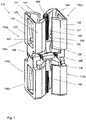
- Fig. 1 shows a connecting device 10 according to a first embodiment in a first functional position.
- This functional position is a position in which the connecting device 10 is in a partially open or relaxed position. In this position it is possible to connect the connecting device 10 to the desired element, such as a component or pontoon element, to which it is to be connected.
- Fig. 2 is the connecting device of the Fig. 1 shown in a partially closed or tensioned or assembled state, in which the connecting device 10 connects two components to one another.
- the connecting device 10 comprises two block-like base bodies 12a, 12b each with an upper side 16a, 16b, a lower side 18a, 18b, a first end side 20a, 20b, a second end side 22a, 22b, and two opposite longitudinal sides 24a, 24b.
- the two block-like base bodies 12a, 12b are constructed identically. They are arranged one above the other and parallel to one another at a distance from one another and are connected to one another via a holder 26, the two undersides 18a, 18b of the base body 12a, 12b being opposite one another. In this arrangement, the top side 16a of the first base body 12a and the top side 16b of the second base body 16b each point outwards.
- the base body 12a, 12b has a middle section 28a, 28b and two end sections 30a, 30b which are opposite to the middle section 28a, 28b.
- the first and second end faces 20a, 20b, 22a, 22b of the base body 12a, 12b are at the same time the first and second end faces, respectively, of the end section 30a, 30b.
- the base body 12a, 12b tapers from one end section 30a, 30b of the base body 12a, 12b to the middle section 28a, 28b of the base body 12a, 12b and then widens again in the direction of the other end section 30a, 30b of the base body 12a, 12b.
- the longitudinal sides 24a, 24b are beveled in the end section of the base body 12.
- the base body 12a, 12b thus has an axially symmetrical funnel shape.
- a groove 32a, 32b On each end face 20a, 20b, 22a, 22b of the base body 12a, 12b, a groove 32a, 32b is provided which has a T-shaped cross section, extends from the top side 16a, 16b to the bottom side 18a, 18b of the base body 12a, 12b and is open to the top 16a, 16b and bottom 18a, 18b of the base body 12a, 12b.
- Each groove 32a, 32b has a predetermined inclination with respect to the end face 20a, 20b, 22a, 22b of the base body 12a, 12b.
- a connecting unit 34 is provided on each end face of the two base bodies 20a, 20b, 22a, 22b.
- connection unit 34 comprises a fastening element 36, an adjustment body 38 and an adjustment device.
- the adjusting device in turn comprises an adjusting rod 40 and an adjusting means.
- connection unit 34 on an end face 20a, 20b, 22a, 22b of the base body 12a, 12b is described below.
- the fastening element 36 has a block-like basic structure with a beveled side surface 44.
- the fastening element 36 is arranged on the end face 20a, 20b, 22a, 22b of the base body 12a, 12b, the beveled side surface 44 of the fastening element 36 facing the end face 20a, 20b, 22a, 22b of the base body 12a, 12b has.
- a T-shaped groove 46 is provided which is inclined in a mirror-inverted manner to the groove 32a, 32b in the base body 12a, 12b.
- two parallel and spaced-apart connecting rods 48 are provided perpendicular to the end face 20a, 20b, 22a, 22b of the base body 12a, 12b.
- the connecting rods 48 connect the fastening element 36 and the base body 12a, 12b 12a, 12b, one end of each connecting rod being firmly connected to the base body 12a, 12b and the other end of the connecting rod 48 being slidably mounted in an opening in the fastening element 36.
- the two connecting rods 148 thus form a connecting part with the aid of which the fastening element 36 can be displaced along the connecting rod 48 in order to be able to vary the distance between the fastening element 36 and the base body 12a, 12b.
- the connecting rod 48 ensures that the fastening element 36 and the base body 12a, 12b always move in the same plane.
- the connecting rod 48 is firmly connected to the fastening element 36 and is arranged displaceably in an opening of the base body 12a, 12b.
- the adjustment body 38 is arranged between the base body 12a, 12b and the fastening element 36 and between the two parallel connecting rods 48. It is designed as a wedge-shaped block with a longitudinal axis, the wedge tip pointing to the top side 16a, 16b of the base body 12a, 12b.
- the adjustment body 38 has two opposite longitudinal sides 52, two opposite transverse sides 54, an upper side 56 and a lower side 58. Furthermore, a through-hole 60 with a thread pointing parallel to the longitudinal axis of the adjustment body 38 is provided.
- the transverse sides 54 of the adjustment body 38 are inclined with respect to the longitudinal axis of the adjustment body 38 and thus with respect to the through hole 60.
- the angle of inclination of the transverse sides 54 corresponds to the angle of inclination of the groove 46 in the fastening element 36 or the angle of inclination of the groove 32a, 32b in the base body 12a, 12b, so that the transverse sides of the adjustment body 38 along the end face 20a, 20b, 22a, 22b of the Base body 12a, 12b or can slide along the beveled side surface 44 of the fastening element 36.
- the Transverse sides 54 of the adjustment body 38 form contact sides to the fastening element 36 or the base body 12a, 12b.
- Guide strips 62 are provided on the respective end sections of the longitudinal sides of the adjustment body 38 and extend along the two inclined edges of the two longitudinal sides 52 of the adjustment body 38.
- the adjusting body 38 thus has a double-T-shaped contour.
- the size of the guide strips 62 and the width of the transverse sides 54 of the adjustment body 38 are selected so that the end section can be moved precisely in the T-shaped groove 46 of the fastening element 36 or in the T-shaped groove 32a, 32b of the base body 12a, 12b .
- the end section of the adjustment body 38 thus forms a profile element which can be displaced in the T-shaped groove 46 of the fastening element 36 or in the T-shaped groove 32a, 32b of the base body 12a, 12b.
- the profile element forms a linear guide unit, the guide strips 62 serving as lateral guides.
- the guide strips 62 are thus also part of a counter-guide element for the guide element designed as a groove 32a, 32b.
- the adjusting rod 40 has a threaded section 64 (see FIG Fig. 2 ) on.
- other known adjusting means such as handles, can also be used.
- One end section of the adjusting rod 40 is located in the through-hole 60 of the adjusting body 38, the threaded section 64 of the adjusting rod 40 interacting with the thread of the through-hole 60 and the wedge-shaped end of the adjusting body 38 pointing towards the end of the adjusting rod 40.
- a fixing element 68 is provided which is fastened to the holder 26 and has a passage 70 for the adjusting rod 40.
- the adjusting rod 40 is rotatably mounted in the passage 70 of the fixing element 68.
- a blocking against a longitudinal displacement of the adjusting rod 40 in the fixing element 68 is provided.
- the blocking is formed in that the adjusting rod 40 has a recess 72 on its outside.
- the recess 72 is designed in a ring shape on the outside of the adjusting rod 40, the fixing element 68 being positioned in sections in the recess 72.
- the screw 66 is rotated by means of a corresponding tool, so that the adjusting rod 40 is rotated. Since the adjusting rod 40 rotates, but is not longitudinally displaceable, the adjusting body 38 slides along the Adjusting rod 40. Depending on the direction of rotation of the adjusting rod 40, the adjusting body 38 slides either in the direction of the top side 16a, 16b or the bottom side 18a, 18b of the base body 12a, 12b.
- the distance between the base body 12a, 12b and the fastening element 36 is increased because the adjustment body is driven in a wedge-like manner between the base body 12a, 12b and the fastening element 36. Since the base body 12a, 12b and the fastening element 36 are connected to one another via the connecting rods 48, the base body 12a, 12b and the fastening element 36 remain in one plane during the adjustment process.
- the connecting device 10 is in its closed position ( Fig. 2 ) brought.
- the adjustment body 38 slides along the guide strips 62 on the fastening element 36 or on the base body 12a, 12b. Since the fastening element 36 can only perform a movement perpendicular to the longitudinal axis of the connecting rod 48 due to the connecting rod 48, the movement of the adjusting body 38 in the direction of the underside 18a, 18b of the base body 12a, 12b causes the fastening element 36 to be pulled onto the base element 12a, 12b and the distance between the fastening element 36 and the base element 12a, 12b is reduced. The connecting device 10 is thereby moved from a closed position to an open position ( Fig. 1 ) brought.
- FIG. 1 and 2 the end positions of a closed position or an open position of the connecting device 10 are not shown. In many applications it is not necessary to transfer the connecting device 10 from a completely closed position to an open position or vice versa. A partially open position is often sufficient to position a connection device 10 or a partially closed position to fix a connection device 10 on a component.
- a connecting unit 34 is provided on each of the four end faces of the base body 12a, 12b.
- the two adjustment rods 40 on the first end face 20a, 20b of the first and second base body 12a, 12b and the two adjustment rods on the second end face 22a, 22b of the first and second base body 12a, 12b are integrally connected to one another.
- Each adjusting rod 40 thus has threaded sections 64 at both of its ends.
- the length of each adjusting rod 40 is selected such that the end sections of the adjusting rods 40 provided with the thread are respectively are arranged at least in sections in the bore of the adjustment body 38.
- the adjustment means can be provided on both end faces of the adjustment rod 40.
- each connecting unit 34 point with the wedge tip outwards in the direction of the top side 16a, 16b of the base body 12a, 12b, so that the connecting device 10 is axially symmetrical with respect to an axis parallel to the longitudinal axis of the adjusting rod 40 and axially symmetrical with respect to an axis perpendicular to the longitudinal axis of the adjusting rod 40 is formed.
- both adjusting bodies 38 connected to the adjusting rod 40 move the correspondingly assigned fastening body 36 in the same direction. Both fastening bodies 36 can thus be brought from an open to a closed position or vice versa at the same time.
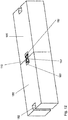
- Each pontoon element 80 comprises a recess 82.
- the recess 82 is designed as a groove 84 open at both ends.
- the cross section of the groove 84 has a basic shape which is essentially complementary to one half of the contour of the connecting device 10 in cross section.
- Two pontoon elements 80 arranged next to one another thus have a recess 82 which essentially corresponds to the contour of the cross section of the connecting device 10.
- the groove 84 has a groove opening 86 which has a smaller width than the groove 84 in the interior.
- the width of the groove opening 86 is somewhat larger than the width of the central section 28a, 28b of the base body 12a, 12b, so that there is play here.
- the groove 84 has inclined wall sections 88 on which the inclined longitudinal sides 24a, 24b of an end section 30a, 30b of the base body 12a, 12b rest.
- the inclined wall sections 88 of the groove 84 form a stop surface for the inclined longitudinal sides 24a, 24b of the connecting device 10, so that a section of the connecting device 10 can be firmly attached, in particular clamped, in the recess 82 or groove 84 of the pontoon element 80.
- the two pontoon elements 80 are placed against one another and the connecting device 10 is inserted from the top of the pontoon elements 80 with play into the recesses 82 of the two pontoon elements 80.
- Fig. 5 the state in which the connecting device 10 is located inside the two recesses 82 of the pontoon elements 80 to be connected can be seen.
- the connecting device 10 is located in the recesses 82 of the pontoon elements 80 in its clamped or closed position, the fastening element resting against the inside of the groove 84 so that the two pontoon elements are firmly connected to one another.
- connection device 10 has the in Fig. 1 unopened condition shown.
- the connecting device 10 can be operated as described above in order to clamp the two pontoon elements 80 firmly together (see Fig. 6 ).
- connection units 34 on two base bodies 12a, 12b arranged one above the other has the advantage that the pontoon elements 80 can be held in a rotationally secure manner.
- the risk of two pontoon elements 80 connected to one another rotating about their connecting axis is very low with this connecting device 10.
- a component such as a railing or a post can be provided on an end face of the base body, so that, for example, components can be attached to pontoon elements.
- a base body and the corresponding connection units provided on the base body can be omitted, so that the connection device comprises only one base body, on the two end faces of which a connection unit can be provided.
- This embodiment is useful when the height of the components to be connected is low.
- Fig. 7 shows a connecting device 110 according to a second embodiment in a first functional position.
- This functional position is a position in which the connecting device 110 is in a partially open or relaxed position. In this position it is possible to connect the connecting device 110 to the desired element, such as a component or pontoon element, to which it is to be connected.
- Fig. 8 is the connecting device of the Fig. 7 shown in a partially closed or tensioned or assembled state, in which the connecting device 110 connects two components to one another.
- the connecting device 110 comprises two base bodies 112a, 112b which are arranged one above the other and which are connected to one another in one piece.
- a connecting unit 134a, 134b is provided on each base body 112a, 112b.
- Each connecting unit 134a, 134b comprises a fastening element 136a, 136b, the two fastening elements 136a, 136b being firmly connected to one another.
- the two interconnected fastening elements 136a and 136b and the two interconnected base bodies 112a, 112b are of identical construction and are therefore interchangeable with one another.
- Each fastening element 136a, 136b has the basic shape of a hollow profile element open on one side with a rear wall 137 and two side walls 139, which is C-shaped in cross section.
- the rear wall 137 of the fastening element 136a, 136b forms a wall on which guide elements are provided.
- the guide elements are formed by the two side walls 139 of the fastening element 136a, 136b, the side walls 139 each having a first section 141 which is oriented perpendicular to the rear wall 137 and a second section 143 which is bent inward relative to the first section 141.
- the inside of the rear wall 137 and the inside of the side walls 139 form a groove in which the adjusting element 138 can be displaced.
- the outer wall of the second section 143 serves, as described further below, as a stop surface for a component.
- the base body 112a, 112b and the fastening element 136a, 136b are arranged such that their open sides face one another.
- An adjustment body 138 is provided between each base body 112a, 112b and fastening element 136a, 136b, which is slidably mounted in the fastening element 136a, 136b or base body 112a, 112b, the adjustment body 138 being guided along the side guides 145.
- the adjustment body 138 has, seen in cross section, a central section 151 and two end sections 153 which are aligned opposite to one another (see FIG Fig. 8 ).
- the end sections 153 each have a contour that is complementary to the cross section of the fastening element 136a, 136b or the base body 112a, 112b, so that the fastening element 136a, 136b or the base body 112a, 112b the respective end sections 153 of the adjustment body 138 encompass.
- the adjusting body 138 has a through-hole 160 with a thread along its longitudinal axis, in which an adjusting rod 140 in the form of a spindle is rotatably guided.
- the transverse sides of the adjustment body 138 which point towards the base body 112a, 112b or fastening element 136a, 136b, are inclined with respect to the longitudinal axis of the adjustment body 138.
- the adjustment body 138 has a wedge-shaped basic shape, the wedge tips of both adjustment bodies 138, in contrast to the first embodiment of the adjustment device 10, each pointing inward or facing one another. Viewed in the longitudinal direction of the adjustment body 138, the adjustment body 138 has a shorter length than the fastening element 136a, 136b.
- the two spindles of the connecting device 110 are integrally connected to one another and are rotatably but stationary in a fixing element 168 which is provided between the two base bodies 112a, 112b or between the two fastening elements 136a, 136b.
- a fixing element 168 which is provided between the two base bodies 112a, 112b or between the two fastening elements 136a, 136b.
- corresponding blocking elements are provided.
- the base body 112a, 112b and the fastening element 136a, 136b are connected to one another via connecting rods 148 which are perpendicular to the spindle.
- the connecting rods 148 are arranged in the fixing element 168, which supports the spindle in a rotatable and stationary manner.
- adjusting screws 166 are provided at the free ends of the adjusting rod 140. If these are rotated, both adjusting elements 138 move along the spindles. Depending on the direction of rotation, the two adjusting bodies 138 move towards or away from one another.
- each adjustment body 138 presses the main body 112a, 112b resting against it and the fastening element 136a, 136b resting against it apart, so that the connecting device moves into its open or first functional position.
- the connecting rods 148 ensure that the fastening element 136a, 136b and the base body 112a, 112b move in one plane.
- each adjustment body 138 pulls the base body 112a, 112b resting against it and the fastening element 136a, 136b resting against it towards one another by guiding the adjustment body 138 along the inclined side guides 145.
- the connecting device 110 is in its clamped or second functional position.
- the connecting device 110 is inserted and prepositioned in two opposing recesses 182 of two components arranged next to one another, such as pontoon elements 180.
- the two opposing recesses 182 have the same contour in cross section as the connecting device 110.
- the recess 182 is designed as a groove open at both ends and thus has a rear wall 183 and two side walls, each side wall having a first, perpendicular to the rear wall standing section 185 and a second section 187 bent relative to the first section.
- the distance between the fastening element 136a, 136b and the base element 112a, 112b is greater than in the clamped or second functional position. There is a gap between the two pontoon elements 182.
- the spindle is rotated by means of the adjusting screw 166 located on the end face of the spindle and the fastening element 136a, 136b and the base body 112a, 112b approach.
- the beveled side surfaces 141 of the fastening element 136a, 136b or of the base body 112a, 112b rest on the beveled second section 187 of the side wall of the recess 182.
- the two pontoon elements 182 rest against one another without a gap.
- a connecting device can be omitted in a variant not shown, one of the two base bodies and the corresponding connecting unit.
- connection is also not, as shown, limited to the transverse sides of the pontoon element.
- the pontoon elements also have corresponding recesses on the longitudinal sides, so that not only elongated but also flat pontoon bridge elements can be produced.
- the connecting devices can also be used on any other structural elements that have a corresponding recess for receiving at least one section of the connecting device.
Landscapes
- Engineering & Computer Science (AREA)
- General Engineering & Computer Science (AREA)
- Mechanical Engineering (AREA)
- Architecture (AREA)
- Civil Engineering (AREA)
- Structural Engineering (AREA)
- Bridges Or Land Bridges (AREA)
Priority Applications (1)
| Application Number | Priority Date | Filing Date | Title |
|---|---|---|---|
| EP20177827.1A EP3919683B1 (fr) | 2020-06-02 | 2020-06-02 | Dispositif de raccordement |
Applications Claiming Priority (1)
| Application Number | Priority Date | Filing Date | Title |
|---|---|---|---|
| EP20177827.1A EP3919683B1 (fr) | 2020-06-02 | 2020-06-02 | Dispositif de raccordement |
Publications (3)
| Publication Number | Publication Date |
|---|---|
| EP3919683A1 true EP3919683A1 (fr) | 2021-12-08 |
| EP3919683B1 EP3919683B1 (fr) | 2023-08-30 |
| EP3919683C0 EP3919683C0 (fr) | 2023-08-30 |
Family
ID=70975796
Family Applications (1)
| Application Number | Title | Priority Date | Filing Date |
|---|---|---|---|
| EP20177827.1A Active EP3919683B1 (fr) | 2020-06-02 | 2020-06-02 | Dispositif de raccordement |
Country Status (1)
| Country | Link |
|---|---|
| EP (1) | EP3919683B1 (fr) |
Families Citing this family (1)
| Publication number | Priority date | Publication date | Assignee | Title |
|---|---|---|---|---|
| AT527292B1 (de) * | 2023-10-18 | 2025-01-15 | Sihga GmbH | Beschlag für das Verbinden eines Holzbauteiles mit einem weiteren Teil |
Citations (5)
| Publication number | Priority date | Publication date | Assignee | Title |
|---|---|---|---|---|
| FR2490297A1 (fr) * | 1980-09-18 | 1982-03-19 | Michel Martial | Goujon de fixation |
| DE3803292A1 (de) * | 1988-02-04 | 1989-08-24 | Eisenberg Hans Jochen | Verbinder fuer zwei mit ihren offenen seiten einander zugewandte c-profilschienen |
| US5356692A (en) * | 1992-07-27 | 1994-10-18 | Lockheed Missiles & Space Company, Inc. | Grid structure with sinuous interstices |
| WO2007057635A1 (fr) * | 2005-11-15 | 2007-05-24 | Fergus Ardern | Systeme de pontage |
| KR101986978B1 (ko) * | 2019-03-06 | 2019-06-10 | 주식회사 혁신 | 해상부유구조물 |
-
2020
- 2020-06-02 EP EP20177827.1A patent/EP3919683B1/fr active Active
Patent Citations (5)
| Publication number | Priority date | Publication date | Assignee | Title |
|---|---|---|---|---|
| FR2490297A1 (fr) * | 1980-09-18 | 1982-03-19 | Michel Martial | Goujon de fixation |
| DE3803292A1 (de) * | 1988-02-04 | 1989-08-24 | Eisenberg Hans Jochen | Verbinder fuer zwei mit ihren offenen seiten einander zugewandte c-profilschienen |
| US5356692A (en) * | 1992-07-27 | 1994-10-18 | Lockheed Missiles & Space Company, Inc. | Grid structure with sinuous interstices |
| WO2007057635A1 (fr) * | 2005-11-15 | 2007-05-24 | Fergus Ardern | Systeme de pontage |
| KR101986978B1 (ko) * | 2019-03-06 | 2019-06-10 | 주식회사 혁신 | 해상부유구조물 |
Also Published As
| Publication number | Publication date |
|---|---|
| EP3919683B1 (fr) | 2023-08-30 |
| EP3919683C0 (fr) | 2023-08-30 |
Similar Documents
| Publication | Publication Date | Title |
|---|---|---|
| EP0596986B1 (fr) | Vis orthodontique d'extension | |
| EP1411871A1 (fr) | Element d'ecartement de longueur axiale modifiable | |
| EP3905992B1 (fr) | Implant intervertébral | |
| DE102009017338A1 (de) | Halter für Sicherungen | |
| EP1394012B1 (fr) | Dispositif de fixation pour deux elements monté coulissant l'un par rapport à l'autre | |
| AT393302B (de) | Vorrichtung zur verbindung zweier werkzeugteile | |
| EP1704957A1 (fr) | Dispositif d'accouplement avec des parties élastiques pour une orientation en X et Y. | |
| DE3941937C2 (fr) | ||
| DE202021103863U1 (de) | Vorrichtung zum Positionieren eines Bauelementes | |
| EP1482187B1 (fr) | Dispositif pour relier des extrémités de barre | |
| EP3919683B1 (fr) | Dispositif de raccordement | |
| DE2325148C3 (de) | Vorrichtung zum Zusammenbau von Profilen für Metallstrukturen | |
| DE3941935C2 (de) | Spannschloß | |
| EP0512230A2 (fr) | Dispositif interchangeable pour mâchoirs de serrage de mandrin de tour | |
| DE3241105A1 (de) | Dehnschraube fuer kieferndehnvorrichtungen | |
| EP0509267B1 (fr) | Dispositif de serrage comprenant un dispositif de positionnement rapide avec amplificateur de force | |
| EP2066197A1 (fr) | Dispositif de réglage | |
| DE29921046U1 (de) | Knochendistraktor | |
| DE10319523A1 (de) | Vorrichtung beim nachlaufenden Zweistufen-Auswerfer vom Einbautyp | |
| DE102022109309B3 (de) | Niederzugspanner | |
| DE102015105481A1 (de) | Profilverbinder | |
| DE10151912C1 (de) | Verbinder für Profilstäbe, die eine hinterschnittene Nut aufweisen, sowie Verfahren zum Verbinden von Profilstäben | |
| EP3708287B1 (fr) | Chariot de déplacement pour une machine à souder, en particulier pour une machine à souder de grillage | |
| EP4245928A1 (fr) | Bouche d'incendie | |
| EP3557111B1 (fr) | Dispositif de positionnement permettant l'alignement de composants d'installation plus lourds |
Legal Events
| Date | Code | Title | Description |
|---|---|---|---|
| PUAI | Public reference made under article 153(3) epc to a published international application that has entered the european phase |
Free format text: ORIGINAL CODE: 0009012 |
|
| STAA | Information on the status of an ep patent application or granted ep patent |
Free format text: STATUS: REQUEST FOR EXAMINATION WAS MADE |
|
| 17P | Request for examination filed |
Effective date: 20210520 |
|
| AK | Designated contracting states |
Kind code of ref document: A1 Designated state(s): AL AT BE BG CH CY CZ DE DK EE ES FI FR GB GR HR HU IE IS IT LI LT LU LV MC MK MT NL NO PL PT RO RS SE SI SK SM TR |
|
| B565 | Issuance of search results under rule 164(2) epc |
Effective date: 20201119 |
|
| GRAP | Despatch of communication of intention to grant a patent |
Free format text: ORIGINAL CODE: EPIDOSNIGR1 |
|
| STAA | Information on the status of an ep patent application or granted ep patent |
Free format text: STATUS: GRANT OF PATENT IS INTENDED |
|
| INTG | Intention to grant announced |
Effective date: 20221208 |
|
| GRAJ | Information related to disapproval of communication of intention to grant by the applicant or resumption of examination proceedings by the epo deleted |
Free format text: ORIGINAL CODE: EPIDOSDIGR1 |
|
| STAA | Information on the status of an ep patent application or granted ep patent |
Free format text: STATUS: REQUEST FOR EXAMINATION WAS MADE |
|
| GRAP | Despatch of communication of intention to grant a patent |
Free format text: ORIGINAL CODE: EPIDOSNIGR1 |
|
| STAA | Information on the status of an ep patent application or granted ep patent |
Free format text: STATUS: GRANT OF PATENT IS INTENDED |
|
| INTC | Intention to grant announced (deleted) | ||
| INTG | Intention to grant announced |
Effective date: 20230412 |
|
| GRAS | Grant fee paid |
Free format text: ORIGINAL CODE: EPIDOSNIGR3 |
|
| GRAA | (expected) grant |
Free format text: ORIGINAL CODE: 0009210 |
|
| STAA | Information on the status of an ep patent application or granted ep patent |
Free format text: STATUS: THE PATENT HAS BEEN GRANTED |
|
| AK | Designated contracting states |
Kind code of ref document: B1 Designated state(s): AL AT BE BG CH CY CZ DE DK EE ES FI FR GB GR HR HU IE IS IT LI LT LU LV MC MK MT NL NO PL PT RO RS SE SI SK SM TR |
|
| REG | Reference to a national code |
Ref country code: GB Ref legal event code: FG4D Free format text: NOT ENGLISH |
|
| REG | Reference to a national code |
Ref country code: CH Ref legal event code: EP |
|
| REG | Reference to a national code |
Ref country code: DE Ref legal event code: R096 Ref document number: 502020004932 Country of ref document: DE |
|
| REG | Reference to a national code |
Ref country code: IE Ref legal event code: FG4D Free format text: LANGUAGE OF EP DOCUMENT: GERMAN |
|
| U01 | Request for unitary effect filed |
Effective date: 20230927 |
|
| U07 | Unitary effect registered |
Designated state(s): AT BE BG DE DK EE FI FR IT LT LU LV MT NL PT SE SI Effective date: 20231005 |
|
| PG25 | Lapsed in a contracting state [announced via postgrant information from national office to epo] |
Ref country code: GR Free format text: LAPSE BECAUSE OF FAILURE TO SUBMIT A TRANSLATION OF THE DESCRIPTION OR TO PAY THE FEE WITHIN THE PRESCRIBED TIME-LIMIT Effective date: 20231201 |
|
| PG25 | Lapsed in a contracting state [announced via postgrant information from national office to epo] |
Ref country code: IS Free format text: LAPSE BECAUSE OF FAILURE TO SUBMIT A TRANSLATION OF THE DESCRIPTION OR TO PAY THE FEE WITHIN THE PRESCRIBED TIME-LIMIT Effective date: 20231230 |
|
| PG25 | Lapsed in a contracting state [announced via postgrant information from national office to epo] |
Ref country code: RS Free format text: LAPSE BECAUSE OF FAILURE TO SUBMIT A TRANSLATION OF THE DESCRIPTION OR TO PAY THE FEE WITHIN THE PRESCRIBED TIME-LIMIT Effective date: 20230830 Ref country code: NO Free format text: LAPSE BECAUSE OF FAILURE TO SUBMIT A TRANSLATION OF THE DESCRIPTION OR TO PAY THE FEE WITHIN THE PRESCRIBED TIME-LIMIT Effective date: 20231130 Ref country code: IS Free format text: LAPSE BECAUSE OF FAILURE TO SUBMIT A TRANSLATION OF THE DESCRIPTION OR TO PAY THE FEE WITHIN THE PRESCRIBED TIME-LIMIT Effective date: 20231230 Ref country code: HR Free format text: LAPSE BECAUSE OF FAILURE TO SUBMIT A TRANSLATION OF THE DESCRIPTION OR TO PAY THE FEE WITHIN THE PRESCRIBED TIME-LIMIT Effective date: 20230830 Ref country code: GR Free format text: LAPSE BECAUSE OF FAILURE TO SUBMIT A TRANSLATION OF THE DESCRIPTION OR TO PAY THE FEE WITHIN THE PRESCRIBED TIME-LIMIT Effective date: 20231201 |
|
| PG25 | Lapsed in a contracting state [announced via postgrant information from national office to epo] |
Ref country code: PL Free format text: LAPSE BECAUSE OF FAILURE TO SUBMIT A TRANSLATION OF THE DESCRIPTION OR TO PAY THE FEE WITHIN THE PRESCRIBED TIME-LIMIT Effective date: 20230830 |
|
| PG25 | Lapsed in a contracting state [announced via postgrant information from national office to epo] |
Ref country code: ES Free format text: LAPSE BECAUSE OF FAILURE TO SUBMIT A TRANSLATION OF THE DESCRIPTION OR TO PAY THE FEE WITHIN THE PRESCRIBED TIME-LIMIT Effective date: 20230830 |
|
| PG25 | Lapsed in a contracting state [announced via postgrant information from national office to epo] |
Ref country code: SM Free format text: LAPSE BECAUSE OF FAILURE TO SUBMIT A TRANSLATION OF THE DESCRIPTION OR TO PAY THE FEE WITHIN THE PRESCRIBED TIME-LIMIT Effective date: 20230830 Ref country code: RO Free format text: LAPSE BECAUSE OF FAILURE TO SUBMIT A TRANSLATION OF THE DESCRIPTION OR TO PAY THE FEE WITHIN THE PRESCRIBED TIME-LIMIT Effective date: 20230830 Ref country code: ES Free format text: LAPSE BECAUSE OF FAILURE TO SUBMIT A TRANSLATION OF THE DESCRIPTION OR TO PAY THE FEE WITHIN THE PRESCRIBED TIME-LIMIT Effective date: 20230830 Ref country code: CZ Free format text: LAPSE BECAUSE OF FAILURE TO SUBMIT A TRANSLATION OF THE DESCRIPTION OR TO PAY THE FEE WITHIN THE PRESCRIBED TIME-LIMIT Effective date: 20230830 Ref country code: SK Free format text: LAPSE BECAUSE OF FAILURE TO SUBMIT A TRANSLATION OF THE DESCRIPTION OR TO PAY THE FEE WITHIN THE PRESCRIBED TIME-LIMIT Effective date: 20230830 |
|
| REG | Reference to a national code |
Ref country code: DE Ref legal event code: R097 Ref document number: 502020004932 Country of ref document: DE |
|
| U20 | Renewal fee for the european patent with unitary effect paid |
Year of fee payment: 5 Effective date: 20240503 |
|
| PLBE | No opposition filed within time limit |
Free format text: ORIGINAL CODE: 0009261 |
|
| STAA | Information on the status of an ep patent application or granted ep patent |
Free format text: STATUS: NO OPPOSITION FILED WITHIN TIME LIMIT |
|
| 26N | No opposition filed |
Effective date: 20240603 |
|
| PG25 | Lapsed in a contracting state [announced via postgrant information from national office to epo] |
Ref country code: MC Free format text: LAPSE BECAUSE OF FAILURE TO SUBMIT A TRANSLATION OF THE DESCRIPTION OR TO PAY THE FEE WITHIN THE PRESCRIBED TIME-LIMIT Effective date: 20230830 |
|
| REG | Reference to a national code |
Ref country code: CH Ref legal event code: PL |
|
| GBPC | Gb: european patent ceased through non-payment of renewal fee |
Effective date: 20240602 |
|
| PG25 | Lapsed in a contracting state [announced via postgrant information from national office to epo] |
Ref country code: IE Free format text: LAPSE BECAUSE OF NON-PAYMENT OF DUE FEES Effective date: 20240602 |
|
| PG25 | Lapsed in a contracting state [announced via postgrant information from national office to epo] |
Ref country code: CH Free format text: LAPSE BECAUSE OF NON-PAYMENT OF DUE FEES Effective date: 20240630 |
|
| PG25 | Lapsed in a contracting state [announced via postgrant information from national office to epo] |
Ref country code: GB Free format text: LAPSE BECAUSE OF NON-PAYMENT OF DUE FEES Effective date: 20240602 |
|
| U20 | Renewal fee for the european patent with unitary effect paid |
Year of fee payment: 6 Effective date: 20250506 |
|
| PG25 | Lapsed in a contracting state [announced via postgrant information from national office to epo] |
Ref country code: CY Free format text: LAPSE BECAUSE OF FAILURE TO SUBMIT A TRANSLATION OF THE DESCRIPTION OR TO PAY THE FEE WITHIN THE PRESCRIBED TIME-LIMIT; INVALID AB INITIO Effective date: 20200602 |
|
| PG25 | Lapsed in a contracting state [announced via postgrant information from national office to epo] |
Ref country code: HU Free format text: LAPSE BECAUSE OF FAILURE TO SUBMIT A TRANSLATION OF THE DESCRIPTION OR TO PAY THE FEE WITHIN THE PRESCRIBED TIME-LIMIT; INVALID AB INITIO Effective date: 20200602 |