EP3920008A1 - Procédé de commande d'affichage d'écran et dispositif électronique - Google Patents
Procédé de commande d'affichage d'écran et dispositif électronique Download PDFInfo
- Publication number
- EP3920008A1 EP3920008A1 EP20759539.8A EP20759539A EP3920008A1 EP 3920008 A1 EP3920008 A1 EP 3920008A1 EP 20759539 A EP20759539 A EP 20759539A EP 3920008 A1 EP3920008 A1 EP 3920008A1
- Authority
- EP
- European Patent Office
- Prior art keywords
- electronic device
- interface
- area
- screen
- display
- Prior art date
- Legal status (The legal status is an assumption and is not a legal conclusion. Google has not performed a legal analysis and makes no representation as to the accuracy of the status listed.)
- Ceased
Links
Images


Classifications
-
- G—PHYSICS
- G06—COMPUTING OR CALCULATING; COUNTING
- G06F—ELECTRIC DIGITAL DATA PROCESSING
- G06F1/00—Details not covered by groups G06F3/00 - G06F13/00 and G06F21/00
- G06F1/16—Constructional details or arrangements
- G06F1/1613—Constructional details or arrangements for portable computers
- G06F1/1615—Constructional details or arrangements for portable computers with several enclosures having relative motions, each enclosure supporting at least one I/O or computing function
- G06F1/1616—Constructional details or arrangements for portable computers with several enclosures having relative motions, each enclosure supporting at least one I/O or computing function with folding flat displays, e.g. laptop computers or notebooks having a clamshell configuration, with body parts pivoting to an open position around an axis parallel to the plane they define in closed position
- G06F1/1618—Constructional details or arrangements for portable computers with several enclosures having relative motions, each enclosure supporting at least one I/O or computing function with folding flat displays, e.g. laptop computers or notebooks having a clamshell configuration, with body parts pivoting to an open position around an axis parallel to the plane they define in closed position the display being foldable up to the back of the other housing with a single degree of freedom, e.g. by 360° rotation over the axis defined by the rear edge of the base enclosure
-
- G—PHYSICS
- G06—COMPUTING OR CALCULATING; COUNTING
- G06F—ELECTRIC DIGITAL DATA PROCESSING
- G06F3/00—Input arrangements for transferring data to be processed into a form capable of being handled by the computer; Output arrangements for transferring data from processing unit to output unit, e.g. interface arrangements
- G06F3/01—Input arrangements or combined input and output arrangements for interaction between user and computer
- G06F3/03—Arrangements for converting the position or the displacement of a member into a coded form
- G06F3/041—Digitisers, e.g. for touch screens or touch pads, characterised by the transducing means
- G06F3/0412—Digitisers structurally integrated in a display
-
- G—PHYSICS
- G06—COMPUTING OR CALCULATING; COUNTING
- G06F—ELECTRIC DIGITAL DATA PROCESSING
- G06F1/00—Details not covered by groups G06F3/00 - G06F13/00 and G06F21/00
- G06F1/16—Constructional details or arrangements
- G06F1/1613—Constructional details or arrangements for portable computers
- G06F1/1633—Constructional details or arrangements of portable computers not specific to the type of enclosures covered by groups G06F1/1615 - G06F1/1626
- G06F1/1637—Details related to the display arrangement, including those related to the mounting of the display in the housing
- G06F1/1641—Details related to the display arrangement, including those related to the mounting of the display in the housing the display being formed by a plurality of foldable display components
-
- G—PHYSICS
- G06—COMPUTING OR CALCULATING; COUNTING
- G06F—ELECTRIC DIGITAL DATA PROCESSING
- G06F1/00—Details not covered by groups G06F3/00 - G06F13/00 and G06F21/00
- G06F1/16—Constructional details or arrangements
- G06F1/1613—Constructional details or arrangements for portable computers
- G06F1/1633—Constructional details or arrangements of portable computers not specific to the type of enclosures covered by groups G06F1/1615 - G06F1/1626
- G06F1/1637—Details related to the display arrangement, including those related to the mounting of the display in the housing
- G06F1/1643—Details related to the display arrangement, including those related to the mounting of the display in the housing the display being associated to a digitizer, e.g. laptops that can be used as penpads
-
- G—PHYSICS
- G06—COMPUTING OR CALCULATING; COUNTING
- G06F—ELECTRIC DIGITAL DATA PROCESSING
- G06F1/00—Details not covered by groups G06F3/00 - G06F13/00 and G06F21/00
- G06F1/16—Constructional details or arrangements
- G06F1/1613—Constructional details or arrangements for portable computers
- G06F1/1633—Constructional details or arrangements of portable computers not specific to the type of enclosures covered by groups G06F1/1615 - G06F1/1626
- G06F1/1637—Details related to the display arrangement, including those related to the mounting of the display in the housing
- G06F1/1652—Details related to the display arrangement, including those related to the mounting of the display in the housing the display being flexible, e.g. mimicking a sheet of paper, or rollable
-
- G—PHYSICS
- G06—COMPUTING OR CALCULATING; COUNTING
- G06F—ELECTRIC DIGITAL DATA PROCESSING
- G06F1/00—Details not covered by groups G06F3/00 - G06F13/00 and G06F21/00
- G06F1/16—Constructional details or arrangements
- G06F1/1613—Constructional details or arrangements for portable computers
- G06F1/1633—Constructional details or arrangements of portable computers not specific to the type of enclosures covered by groups G06F1/1615 - G06F1/1626
- G06F1/1675—Miscellaneous details related to the relative movement between the different enclosures or enclosure parts
- G06F1/1677—Miscellaneous details related to the relative movement between the different enclosures or enclosure parts for detecting open or closed state or particular intermediate positions assumed by movable parts of the enclosure, e.g. detection of display lid position with respect to main body in a laptop, detection of opening of the cover of battery compartment
-
- G—PHYSICS
- G06—COMPUTING OR CALCULATING; COUNTING
- G06F—ELECTRIC DIGITAL DATA PROCESSING
- G06F1/00—Details not covered by groups G06F3/00 - G06F13/00 and G06F21/00
- G06F1/16—Constructional details or arrangements
- G06F1/1613—Constructional details or arrangements for portable computers
- G06F1/1633—Constructional details or arrangements of portable computers not specific to the type of enclosures covered by groups G06F1/1615 - G06F1/1626
- G06F1/1684—Constructional details or arrangements related to integrated I/O peripherals not covered by groups G06F1/1635 - G06F1/1675
- G06F1/1694—Constructional details or arrangements related to integrated I/O peripherals not covered by groups G06F1/1635 - G06F1/1675 the I/O peripheral being a single or a set of motion sensors for pointer control or gesture input obtained by sensing movements of the portable computer
-
- G—PHYSICS
- G06—COMPUTING OR CALCULATING; COUNTING
- G06F—ELECTRIC DIGITAL DATA PROCESSING
- G06F1/00—Details not covered by groups G06F3/00 - G06F13/00 and G06F21/00
- G06F1/26—Power supply means, e.g. regulation thereof
- G06F1/32—Means for saving power
- G06F1/3203—Power management, i.e. event-based initiation of a power-saving mode
- G06F1/3206—Monitoring of events, devices or parameters that trigger a change in power modality
- G06F1/3215—Monitoring of peripheral devices
- G06F1/3218—Monitoring of peripheral devices of display devices
-
- G—PHYSICS
- G06—COMPUTING OR CALCULATING; COUNTING
- G06F—ELECTRIC DIGITAL DATA PROCESSING
- G06F1/00—Details not covered by groups G06F3/00 - G06F13/00 and G06F21/00
- G06F1/26—Power supply means, e.g. regulation thereof
- G06F1/32—Means for saving power
- G06F1/3203—Power management, i.e. event-based initiation of a power-saving mode
- G06F1/3234—Power saving characterised by the action undertaken
- G06F1/325—Power saving in peripheral device
- G06F1/3265—Power saving in display device
-
- G—PHYSICS
- G06—COMPUTING OR CALCULATING; COUNTING
- G06F—ELECTRIC DIGITAL DATA PROCESSING
- G06F1/00—Details not covered by groups G06F3/00 - G06F13/00 and G06F21/00
- G06F1/26—Power supply means, e.g. regulation thereof
- G06F1/32—Means for saving power
- G06F1/3203—Power management, i.e. event-based initiation of a power-saving mode
- G06F1/3234—Power saving characterised by the action undertaken
- G06F1/3287—Power saving characterised by the action undertaken by switching off individual functional units in the computer system
-
- G—PHYSICS
- G06—COMPUTING OR CALCULATING; COUNTING
- G06F—ELECTRIC DIGITAL DATA PROCESSING
- G06F3/00—Input arrangements for transferring data to be processed into a form capable of being handled by the computer; Output arrangements for transferring data from processing unit to output unit, e.g. interface arrangements
- G06F3/01—Input arrangements or combined input and output arrangements for interaction between user and computer
- G06F3/03—Arrangements for converting the position or the displacement of a member into a coded form
- G06F3/041—Digitisers, e.g. for touch screens or touch pads, characterised by the transducing means
- G06F3/0414—Digitisers, e.g. for touch screens or touch pads, characterised by the transducing means using force sensing means to determine a position
-
- G—PHYSICS
- G06—COMPUTING OR CALCULATING; COUNTING
- G06F—ELECTRIC DIGITAL DATA PROCESSING
- G06F3/00—Input arrangements for transferring data to be processed into a form capable of being handled by the computer; Output arrangements for transferring data from processing unit to output unit, e.g. interface arrangements
- G06F3/01—Input arrangements or combined input and output arrangements for interaction between user and computer
- G06F3/03—Arrangements for converting the position or the displacement of a member into a coded form
- G06F3/041—Digitisers, e.g. for touch screens or touch pads, characterised by the transducing means
- G06F3/0416—Control or interface arrangements specially adapted for digitisers
-
- G—PHYSICS
- G06—COMPUTING OR CALCULATING; COUNTING
- G06F—ELECTRIC DIGITAL DATA PROCESSING
- G06F3/00—Input arrangements for transferring data to be processed into a form capable of being handled by the computer; Output arrangements for transferring data from processing unit to output unit, e.g. interface arrangements
- G06F3/01—Input arrangements or combined input and output arrangements for interaction between user and computer
- G06F3/03—Arrangements for converting the position or the displacement of a member into a coded form
- G06F3/041—Digitisers, e.g. for touch screens or touch pads, characterised by the transducing means
- G06F3/044—Digitisers, e.g. for touch screens or touch pads, characterised by the transducing means by capacitive means
-
- G—PHYSICS
- G06—COMPUTING OR CALCULATING; COUNTING
- G06F—ELECTRIC DIGITAL DATA PROCESSING
- G06F3/00—Input arrangements for transferring data to be processed into a form capable of being handled by the computer; Output arrangements for transferring data from processing unit to output unit, e.g. interface arrangements
- G06F3/01—Input arrangements or combined input and output arrangements for interaction between user and computer
- G06F3/048—Interaction techniques based on graphical user interfaces [GUI]
- G06F3/0487—Interaction techniques based on graphical user interfaces [GUI] using specific features provided by the input device, e.g. functions controlled by the rotation of a mouse with dual sensing arrangements, or of the nature of the input device, e.g. tap gestures based on pressure sensed by a digitiser
- G06F3/0488—Interaction techniques based on graphical user interfaces [GUI] using specific features provided by the input device, e.g. functions controlled by the rotation of a mouse with dual sensing arrangements, or of the nature of the input device, e.g. tap gestures based on pressure sensed by a digitiser using a touch-screen or digitiser, e.g. input of commands through traced gestures
- G06F3/04886—Interaction techniques based on graphical user interfaces [GUI] using specific features provided by the input device, e.g. functions controlled by the rotation of a mouse with dual sensing arrangements, or of the nature of the input device, e.g. tap gestures based on pressure sensed by a digitiser using a touch-screen or digitiser, e.g. input of commands through traced gestures by partitioning the display area of the touch-screen or the surface of the digitising tablet into independently controllable areas, e.g. virtual keyboards or menus
-
- G—PHYSICS
- G06—COMPUTING OR CALCULATING; COUNTING
- G06F—ELECTRIC DIGITAL DATA PROCESSING
- G06F40/00—Handling natural language data
- G06F40/10—Text processing
- G06F40/166—Editing, e.g. inserting or deleting
-
- G—PHYSICS
- G06—COMPUTING OR CALCULATING; COUNTING
- G06Q—INFORMATION AND COMMUNICATION TECHNOLOGY [ICT] SPECIALLY ADAPTED FOR ADMINISTRATIVE, COMMERCIAL, FINANCIAL, MANAGERIAL OR SUPERVISORY PURPOSES; SYSTEMS OR METHODS SPECIALLY ADAPTED FOR ADMINISTRATIVE, COMMERCIAL, FINANCIAL, MANAGERIAL OR SUPERVISORY PURPOSES, NOT OTHERWISE PROVIDED FOR
- G06Q20/00—Payment architectures, schemes or protocols
- G06Q20/08—Payment architectures
- G06Q20/14—Payment architectures specially adapted for billing systems
-
- G—PHYSICS
- G06—COMPUTING OR CALCULATING; COUNTING
- G06Q—INFORMATION AND COMMUNICATION TECHNOLOGY [ICT] SPECIALLY ADAPTED FOR ADMINISTRATIVE, COMMERCIAL, FINANCIAL, MANAGERIAL OR SUPERVISORY PURPOSES; SYSTEMS OR METHODS SPECIALLY ADAPTED FOR ADMINISTRATIVE, COMMERCIAL, FINANCIAL, MANAGERIAL OR SUPERVISORY PURPOSES, NOT OTHERWISE PROVIDED FOR
- G06Q20/00—Payment architectures, schemes or protocols
- G06Q20/30—Payment architectures, schemes or protocols characterised by the use of specific devices or networks
- G06Q20/32—Payment architectures, schemes or protocols characterised by the use of specific devices or networks using wireless devices
- G06Q20/327—Short range or proximity payments by means of M-devices
- G06Q20/3274—Short range or proximity payments by means of M-devices using a pictured code, e.g. barcode or QR-code, being displayed on the M-device
-
- H—ELECTRICITY
- H04—ELECTRIC COMMUNICATION TECHNIQUE
- H04M—TELEPHONIC COMMUNICATION
- H04M1/00—Substation equipment, e.g. for use by subscribers
- H04M1/02—Constructional features of telephone sets
- H04M1/0202—Portable telephone sets, e.g. cordless phones, mobile phones or bar type handsets
- H04M1/026—Details of the structure or mounting of specific components
- H04M1/0266—Details of the structure or mounting of specific components for a display module assembly
- H04M1/0268—Details of the structure or mounting of specific components for a display module assembly including a flexible display panel
-
- G—PHYSICS
- G06—COMPUTING OR CALCULATING; COUNTING
- G06F—ELECTRIC DIGITAL DATA PROCESSING
- G06F2203/00—Indexing scheme relating to G06F3/00 - G06F3/048
- G06F2203/041—Indexing scheme relating to G06F3/041 - G06F3/045
- G06F2203/04102—Flexible digitiser, i.e. constructional details for allowing the whole digitising part of a device to be flexed or rolled like a sheet of paper
-
- G—PHYSICS
- G06—COMPUTING OR CALCULATING; COUNTING
- G06F—ELECTRIC DIGITAL DATA PROCESSING
- G06F2203/00—Indexing scheme relating to G06F3/00 - G06F3/048
- G06F2203/048—Indexing scheme relating to G06F3/048
- G06F2203/04803—Split screen, i.e. subdividing the display area or the window area into separate subareas
-
- G—PHYSICS
- G06—COMPUTING OR CALCULATING; COUNTING
- G06F—ELECTRIC DIGITAL DATA PROCESSING
- G06F40/00—Handling natural language data
- G06F40/40—Processing or translation of natural language
- G06F40/58—Use of machine translation, e.g. for multi-lingual retrieval, for server-side translation for client devices or for real-time translation
-
- Y—GENERAL TAGGING OF NEW TECHNOLOGICAL DEVELOPMENTS; GENERAL TAGGING OF CROSS-SECTIONAL TECHNOLOGIES SPANNING OVER SEVERAL SECTIONS OF THE IPC; TECHNICAL SUBJECTS COVERED BY FORMER USPC CROSS-REFERENCE ART COLLECTIONS [XRACs] AND DIGESTS
- Y02—TECHNOLOGIES OR APPLICATIONS FOR MITIGATION OR ADAPTATION AGAINST CLIMATE CHANGE
- Y02D—CLIMATE CHANGE MITIGATION TECHNOLOGIES IN INFORMATION AND COMMUNICATION TECHNOLOGIES [ICT], I.E. INFORMATION AND COMMUNICATION TECHNOLOGIES AIMING AT THE REDUCTION OF THEIR OWN ENERGY USE
- Y02D10/00—Energy efficient computing, e.g. low power processors, power management or thermal management
-
- Y—GENERAL TAGGING OF NEW TECHNOLOGICAL DEVELOPMENTS; GENERAL TAGGING OF CROSS-SECTIONAL TECHNOLOGIES SPANNING OVER SEVERAL SECTIONS OF THE IPC; TECHNICAL SUBJECTS COVERED BY FORMER USPC CROSS-REFERENCE ART COLLECTIONS [XRACs] AND DIGESTS
- Y02—TECHNOLOGIES OR APPLICATIONS FOR MITIGATION OR ADAPTATION AGAINST CLIMATE CHANGE
- Y02D—CLIMATE CHANGE MITIGATION TECHNOLOGIES IN INFORMATION AND COMMUNICATION TECHNOLOGIES [ICT], I.E. INFORMATION AND COMMUNICATION TECHNOLOGIES AIMING AT THE REDUCTION OF THEIR OWN ENERGY USE
- Y02D30/00—Reducing energy consumption in communication networks
- Y02D30/70—Reducing energy consumption in communication networks in wireless communication networks
Definitions
- This application relates to the field of electronic devices, and more specifically, to a screen display control method and an electronic device.
- a foldable screen When in use, a foldable screen may be switched to an unfolded state or a folded state. When carried, the foldable screen is switched to the folded state to reduce space occupation.
- Embodiments of this application provide a screen display control method and an electronic device, to help improve screen utilization.
- a screen display control method is provided.
- the method is applied to an electronic device configured with a foldable touchscreen.
- the touchscreen includes a first area and a second area.
- the method includes: The electronic device displays a first interface in the first area.
- the electronic device detects a first operation in the first interface.
- the electronic device displays a second interface in the second area in response to the first operation.
- the second interface is associated with content displayed in the first interface.
- the electronic device may display content associated with the second area in the second area, thereby helping improve screen utilization and improving user experience.
- the electronic device may be in a folded form.
- the electronic device displays the first interface in the first area, and the second area is turned off for no display. After the electronic device detects the first operation in the first area, the electronic device turns on the second area, and displays the second interface in the second area.
- the electronic device may be in an unfolded form or a half-folded form.
- the electronic device may display the first interface in the first area, and the second area is turned off for no display, or the second area displays a third interface. After the electronic device detects the first operation in the first area, the electronic device turns on the second area, and displays the second interface in the second area, or the electronic device switches the third interface displayed in the second area to the second interface.
- that the electronic device displays a first interface in the first area includes: The electronic device determines that the electronic device is in a folded form. The electronic device displays the first interface in the first area in response to being in the folded form, and the electronic device turns off the second area.
- the electronic device when the electronic device determines that the electronic device is in the folded form, the electronic device may display content in the first area and turn off the second area for no display. After detecting a user operation in the first area, the electronic device turns on the second area, and displays the second interface in the second area. This helps improve screen utilization in the folded form and also improves user experience.
- the method further includes: The electronic device detects a second operation in the first interface. The electronic device turns off the second area in response to the second operation.
- the user when a user expects to exit cooperative work between the first area and the second area, the user may perform a corresponding operation in the first area to exit the cooperative work between the first area and the second area, and turn off the second area. This helps reduce power consumption of the electronic device, and also helps improve user experience.
- the method further includes: The electronic device detects a second operation in the second interface. The electronic device turns off the second area in response to the second operation.
- the cooperative work between the first area and the second area may be exited, and the second area may be turned off.
- content displayed in the second interface is at least partially the same as the content displayed in the first interface.
- the first interface is a camera interface
- the camera interface includes a first preview window
- the second interface includes a second preview window
- images displayed in the first preview window and the second preview window are at least partially the same.
- the screen display control method in this embodiment of this application may be applied to a shooting scenario. After detecting a user operation in the camera interface, the electronic device may display the second preview window in the second area. This can help a photographed person adjust a posture of the photographed person in time, and allow the user to take a satisfactory photo or video while improving screen utilization, thereby helping improve user experience.
- the first interface is a payment interface of a user
- the payment interface includes a payment code
- the second interface includes the payment code
- the screen display control method in this embodiment of this application may be applied to a payment scenario.
- a user pays by using a barcode or a two-dimensional code the barcode or the two-dimensional code may be displayed in the second area, thereby helping improve screen utilization.
- the user does not need to flip the electronic device, thereby facilitating scanning by a merchant, and helping improve user experience.
- the first interface is a translation interface
- the translation interface includes to-be-translated content
- the second interface includes a translation result of the to-be-translated content
- the screen display control method in this embodiment of this application may be applied to a translation scenario. After a user completes translation of to-be-translated content, translated content may be displayed in the second area, thereby helping improve screen utilization. In addition, this can improve efficiency of communication in a foreign language by the user, thereby improving user experience.
- the first interface includes the translation result
- the method further includes: The electronic device detects a modification operation performed by the user on the translation result in the first interface.
- the electronic device displays a modified translation result in the second interface in response to the modification operation.
- the user when determining that to-be-translated content is not inaccurately translated in a translation app, the user may adjust translated content in the first area, and display an accurate translation result in the second area, thereby helping improve user experience.
- this technical solution provides an apparatus for controlling screen display.
- the apparatus is included in an electronic device.
- the apparatus has a function of implementing behavior of the electronic device in the foregoing aspect and the possible implementations of the foregoing aspect.
- the function may be implemented by hardware, or may be implemented by hardware by executing corresponding software.
- the hardware or software includes one or more modules or units corresponding to the foregoing function, for example, a display module or unit, or a detection module or unit.
- this technical solution provides an electronic device, including a foldable touchscreen, one or more processors, a memory, a plurality of applications, and one or more computer programs.
- the one or more computer programs are stored in the memory, and the one or more computer programs include instructions.
- the electronic device is enabled to perform the screen display control method in any possible implementation of the foregoing aspects.
- this technical solution provides an electronic device, including one or more processors and one or more memories.
- the one or more memories are coupled to the one or more processors.
- the one or more memories are configured to store computer program code.
- the computer program code includes computer instructions.
- this technical solution provides a computer storage medium, including computer instructions.
- the computer instructions When the computer instructions are run on an electronic device, the electronic device is enabled to perform the screen display control method in any possible implementation of the foregoing aspects.
- this technical solution provides a computer program product.
- the computer program product When the computer program product is run on an electronic device, the electronic device is enabled to perform the screen display control method in any possible design of the foregoing aspects.
- the electronic device may be a portable electronic device that further includes other functions such as a personal digital assistant function and/or a music player function, for example, a mobile phone, a tablet computer, or a wearable electronic device having a wireless communication function (for example, a smartwatch).
- An example embodiment of the portable electronic device includes but is not limited to a portable electronic device using iOS ® , Android ® , Microsoft ® , or another operating system.
- the portable electronic device may alternatively be another portable electronic device, for example, a laptop computer (Laptop). It should be further understood that, in some other embodiments, the electronic device may alternatively be a desktop computer, but not a portable electronic device.
- FIG. 1 is a schematic structural diagram of an electronic device 100.
- the electronic device 100 may include a processor 110, an external memory interface 120, an internal memory 121, a universal serial bus (universal serial bus, USB) port 130, a charging management module 140, a power management module 141, a battery 142, an antenna 1, an antenna 2, a mobile communications module 150, a wireless communications module 160, an audio module 170, a speaker 170A, a receiver 170B, a microphone 170C, a headset jack 170D, a sensor module 180, a button 190, a motor 191, an indicator 192, a camera 193, a display 194, a subscriber identification module (subscriber identification module, SIM) card interface 195, and the like.
- SIM subscriber identification module
- the structure shown in the embodiments of this application does not constitute a specific limitation on the electronic device 100.
- the electronic device 100 may include more or fewer components than those shown in the figure, or some components may be combined, or some components may be split, or different component arrangements may be used.
- the components shown in the figure may be implemented by hardware, software, or a combination of software and hardware.
- the processor 110 may include one or more processing units.
- the processor 110 may include an application processor (application processor, AP), a modem processor, a graphics processing unit (graphics processing unit, GPU), an image signal processor (image signal processor, ISP), a controller, a video codec, a digital signal processor (digital signal processor, DSP), a baseband processor, and/or a neural-network processing unit (neural-network processing unit, NPU).
- Different processing units may be independent devices, or may be integrated into one or more processors.
- the electronic device 101 may alternatively include one or more processors 110.
- the controller may generate an operation control signal based on instruction operation code and a time sequence signal, to control to read instructions and execute instructions.
- a memory may be further disposed in the processor 110, and is configured to store instructions and data.
- the memory in the processor 110 may be a cache memory.
- the memory may store instructions or data that has just been used or is cyclically used by the processor 110. If the processor 110 needs to use the instructions or the data again, the processor 110 may directly invoke the instructions or the data from the memory, to avoid repeated access. This reduces a waiting time of the processor 110, and improves efficiency of processing data or executing instructions by the electronic device 101.
- the processor 110 may include one or more interfaces.
- the interface may include an inter-integrated circuit (inter-integrated circuit, I2C) interface, an inter-integrated circuit sound (inter-integrated circuit sound, I2S) interface, a pulse code modulation (pulse code modulation, PCM) interface, a universal asynchronous receiver/transmitter (universal asynchronous receiver/transmitter, UART) interface, a mobile industry processor interface (mobile industry processor interface, MIPI), a general-purpose input/output (general-purpose input/output, GPIO) interface, a SIM card interface, a USB port, and/or the like.
- I2C inter-integrated circuit
- I2S inter-integrated circuit sound
- PCM pulse code modulation
- PCM pulse code modulation
- UART universal asynchronous receiver/transmitter
- MIPI mobile industry processor interface
- GPIO general-purpose input/output
- the USB port 130 is a port that conforms to a USB standard specification, and may be specifically a mini USB port, a micro USB port, a USB Type C port, or the like.
- the USB port 130 may be configured to connect to the charger to charge the electronic device 101, or may be configured to transmit data between the electronic device 101 and a peripheral device, or may be configured to connect to a headset to play audio by using the headset.
- an interface connection relationship between the modules shown in the embodiments of the present invention is merely used as an example for description, and does not constitute a limitation on the structure of the electronic device 100.
- the electronic device 100 may alternatively use an interface connection manner different from an interface connection manner in the foregoing embodiment, or use a combination of a plurality of interface connection manners.
- the charging management module 140 is configured to receive a charging input from the charger.
- the charger may be a wireless charger or a wired charger.
- the charging management module 140 may receive a charging input from the wired charger through the USB port 130.
- the charging management module 140 may receive a wireless charging input through a wireless charging coil of the electronic device 100.
- the charging management module 140 may further supply power to the electronic device by using the power management module 141 when the battery 142 is charged.
- the power management module 141 is configured to connect the battery 142 and the charging management module 140 to the processor 110.
- the power management module 141 receives an input from the battery 142 and/or the charging management module 140, and supplies power to the processor 110, the internal memory 121, an external memory, the display 194, the camera 193, the wireless communications module 160, and the like.
- the power management module 141 may be further configured to monitor parameters such as battery power, a battery cycle count, and a battery health status (electric leakage or impedance).
- the power management module 141 may alternatively be disposed in the processor 110.
- the power management module 141 and the charging management module 140 may alternatively be disposed in a same device.
- a wireless communication function of the electronic device 100 may be implemented through the antenna 1, the antenna 2, the mobile communications module 150, the wireless communications module 160, the modem processor, the baseband processor, and the like.
- the antenna 1 and the antenna 2 each are configured to transmit and receive electromagnetic wave signals.
- Each antenna in the electronic device 100 may be configured to cover one or more communication frequency bands. Different antennas may be further multiplexed to improve antenna utilization.
- the antenna 1 may be multiplexed as a diversity antenna in a wireless local area network.
- an antenna may be used in combination with a tuning switch.
- the mobile communications module 150 may provide a wireless communication solution, for example, including 2G/3G/4G/5G wireless communication, that is applied to the electronic device 100.
- the mobile communications module 150 may include at least one filter, a switch, a power amplifier, a low noise amplifier (low noise amplifier, LNA), and the like.
- the mobile communications module 150 may receive an electromagnetic wave through the antenna 1, perform processing such as filtering or amplification on the received electromagnetic wave, and transmit the electromagnetic wave to the modem processor for demodulation.
- the mobile communications module 150 may further amplify a signal modulated by the modem processor, and convert an amplified signal into an electromagnetic wave through the antenna 1 for radiation.
- at least some function modules of the mobile communications module 150 may be disposed in the processor 110.
- at least some function modules of the mobile communications module 150 and at least some modules of the processor 110 may be disposed in a same device.
- the modem processor may include a modulator and a demodulator.
- the modulator is configured to modulate a to-be-sent low-frequency baseband signal into a medium or highfrequency signal.
- the demodulator is configured to demodulate a received electromagnetic wave signal into a low-frequency baseband signal. Then, the demodulator transmits the low-frequency baseband signal obtained through demodulation to the baseband processor for processing.
- the low-frequency baseband signal is processed by the baseband processor, and then transmitted to the application processor.
- the application processor outputs a sound signal through an audio device (which is not limited to the speaker 170A, the receiver 170B, or the like), or displays an image or a video through the display 194.
- the modem processor may be an independent component.
- the modem processor may be independent of the processor 110, and is disposed in a same device as the mobile communications module 150 or another function module.
- the wireless communications module 160 may provide a wireless communication solution that includes a wireless local area network (wireless local area networks, WLAN) (for example, a wireless fidelity (wireless fidelity, Wi-Fi) network), Bluetooth (bluetooth, BT), a global navigation satellite system (global navigation satellite system, GNSS), frequency modulation (frequency modulation, FM), a near field communication (near field communication, NFC) technology, an infrared (infrared, IR) technology, or the like and that is applied to the electronic device 100.
- the wireless communications module 160 may be one or more devices integrating at least one communications processing module.
- the wireless communications module 160 receives an electromagnetic wave through the antenna 2, performs frequency modulation and filtering processing on an electromagnetic wave signal, and sends a processed signal to the processor 110.
- the wireless communications module 160 may further receive a to-be-sent signal from the processor 110, perform frequency modulation and amplification on the signal, and convert the signal into an electromagnetic wave through the antenna 2 for radiation.
- the electronic device 100 implements a display function by using the GPU, the display 194, the application processor, and the like.
- the GPU is a microprocessor for image processing, and connects the display 194 to the application processor.
- the GPU is configured to perform mathematical and geometric calculation, and perform graphics rendering.
- the processor 110 may include one or more GPUs that execute program instructions to generate or change display information.
- the display 194 is configured to display an image, a video, and the like.
- the display 194 includes a display panel.
- the display panel may be a liquid crystal display (liquid crystal display, LCD), an organic light-emitting diode (organic light-emitting diode, OLED), an active-matrix organic light-emitting diode (active-matrix organic light-emitting diode, AMOLED), a flexible light-emitting diode (flex light-emitting diode, FLED), mini-LED, a micro-LED, a micro-OLED, a quantum dot light-emitting diode (quantum dot light-emitting diodes, QLED), or the like
- the electronic device 100 may include one or more displays 194.
- the display 194 shown in FIG. 1 may be folded.
- that the display 194 may be folded means that the display may be folded to any angle at any part and may be maintained at the angle.
- the display 194 may be folded left and right from the center, or may be folded up and down from the middle.
- the display that may be folded is referred to as a foldable display.
- the foldable display may include one screen, or may be a display formed by combining a plurality of screens. This is not limited herein.
- the display 194 of the electronic device 100 may be a flexible display.
- the flexible display attracts much attention due to its unique features and huge potential.
- the flexible display has features of strong flexibility and bendability, and can provide a user with a new interaction manner based on the feature of bendability, to meet more requirements of the user for the electronic device.
- the foldable display on the electronic device may be switched between a small screen in a folded form and a large screen in an expanded form at any time. Therefore, the user also uses a screen splitting function on the electronic device configured with the foldable display more frequently.
- a physical form of the electronic device may also change accordingly.
- a physical form of the electronic device when the display is fully expanded, a physical form of the electronic device may be referred to as an unfolded form.
- a physical form of the electronic device When some areas of the touchscreen are folded, a physical form of the electronic device may be referred to as a folded form. It may be understood that in the following embodiments of this application, a physical form of the electronic device may refer to a physical form of the touchscreen.
- the electronic device 100 may implement a photographing function by using the ISP, the camera 193, the video codec, the GPU, the display 194, the application processor, and the like.
- the ISP is configured to process data fed back by the camera 193. For example, during photographing, a shutter is pressed, and light is transmitted to a photosensitive element of the camera through a lens.
- the photosensitive element of the camera converts an optical signal into an electrical signal, and transmits the electrical signal to the ISP for processing.
- the ISP converts the electrical signal into an image that is perceptible to the eye.
- the ISP may further perform algorithm optimization on noise, brightness, and complexion of the image.
- the ISP may further optimize parameters such as exposure and color temperature of a photographing scenario.
- the ISP may be disposed in the camera 193.
- the camera 193 is configured to capture a static image or a video. An optical image of an object is generated through the lens, and is projected onto the photosensitive element.
- the photosensitive element may be a charge coupled device (charge coupled device, CCD) or a complementary metal-oxide-semiconductor (complementary metal-oxide-semiconductor, CMOS) phototransistor.
- CCD charge coupled device
- CMOS complementary metal-oxide-semiconductor
- the photosensitive element converts an optical signal into an electrical signal, and then transmits the electrical signal to the ISP to convert the electrical signal into a digital image signal.
- the ISP outputs the digital image signal to the DSP for processing.
- the DSP converts the digital image signal into a standard image signal in an RGB format, a YUV format, or the like.
- the electronic device 100 may include one or N cameras 193, where N is a positive integer greater than 1.
- the digital signal processor is configured to process a digital signal, and may process another digital signal in addition to the digital image signal. For example, when the electronic device 100 selects a frequency, the digital signal processor is configured to perform Fourier transformation and the like on frequency energy.
- the video codec is configured to: compress or decompress a digital video.
- the electronic device 100 may support one or more video codecs. Therefore, the electronic device 100 may play or record videos in a plurality of coding formats, for example, MPEG (moving picture experts group, MPEG)-1, MPEG-2, MPEG-3, and MPEG-4.
- MPEG moving picture experts group
- the NPU is a neural-network (neural-network, NN) computing processor, quickly processes input information by referring to a structure of a biological neural network, for example, by referring to a transfer mode between human brain neurons, and may further continuously perform self-learning.
- the electronic device 100 may implement intelligent cognition such as image recognition, facial recognition, speech recognition, and text understanding through the NPU.
- the external memory interface 120 may be configured to connect to an external storage card, for example, a micro SD card, to extend a storage capability of the electronic device 100.
- the external storage card communicates with the processor 110 through the external memory interface 120, to implement a data storage function, for example, to store files such as music and a video in the external memory card.
- the internal memory 121 may be configured to store one or more computer programs, where the one or more computer programs include instructions.
- the processor 110 may run the instructions stored in the internal memory 121, so that the electronic device 101 performs the always on display method provided in some embodiments of this application, various applications, data processing, and the like.
- the internal memory 121 may include a program storage area and a data storage area.
- the program storage area may store an operating system.
- the program storage area may further store one or more applications (for example, Gallery and Contacts), and the like.
- the data storage area may store data (for example, Photos and Contacts) created during use of the electronic device 101.
- the internal memory 121 may include a high-speed random access memory, or may include a nonvolatile memory, for example, at least one magnetic disk storage device, a flash memory device, or a universal flash storage (universal flash storage, UFS).
- the processor 110 may run the instructions stored in the internal memory 121 and/or instructions stored in a memory disposed in the processor 110, so that the electronic device 101 performs the always on display method provided in the embodiments of this application, other applications, data processing, and the like.
- the electronic device 100 may implement audio functions, for example, music playing and recording, by using the audio module 170, the speaker 170A, the receiver 170B, the microphone 170C, the headset jack 170D, the application processor, and the like.
- the sensor module 180 may include a pressure sensor 180A, a gyroscope sensor 180B, a barometric pressure sensor 180C, a magnetic sensor 180D, an acceleration sensor 180E, a distance sensor 180F, an optical proximity sensor 180G, a fingerprint sensor 180H, a temperature sensor 180J, a touch sensor 180K, an ambient light sensor 180L, a bone conduction sensor 180M, and the like.
- the pressure sensor 180A is configured to sense a pressure signal, and may convert the pressure signal into an electrical signal.
- the pressure sensor 180A may be disposed on the display 194.
- There are many types of pressure sensors 180A such as a resistive pressure sensor, an inductive pressure sensor, and a capacitive pressure sensor.
- the capacitive pressure sensor may include at least two parallel plates made of conductive materials. Capacitance between electrodes changes when force is applied to the pressure sensor 180A.
- the electronic device 100 determines pressure intensity based on a change of the capacitance. When a touch operation is performed on the display 194, the electronic device 100 detects a strength of the touch operation based on the pressure sensor 180A.
- the electronic device 100 may also calculate a touch position based on a detection signal of the pressure sensor 180A.
- touch operations that are performed in a same touch position but have different touch operation intensity may correspond to different operation instructions. For example, when a touch operation whose touch operation intensity is less than a first pressure threshold is performed on a Messages icon, an instruction for viewing an SMS message is executed. When a touch operation whose touch operation intensity is greater than or equal to the first pressure threshold is performed on a Messages icon, an instruction for creating a new SMS message is executed.
- the gyroscope sensor 180B may be configured to determine a motion posture of the electronic device 100. In some embodiments, an angular velocity of the electronic device 100 around three axes (namely, axes x, y, and z) may be determined by using the gyroscope sensor 180B.
- the gyroscope sensor 180B may be configured to perform image stabilization during shooting. For example, when the shutter is pressed, the gyroscope sensor 180B detects an angle at which the electronic device 100 jitters, and calculates, based on the angle, a distance for which a lens module needs to compensate, and allows the lens to eliminate the jitter of the electronic device 100 through a reverse motion, to implement image stabilization.
- the gyroscope sensor 180B may be further used in a navigation scenario and a somatic game scenario.
- an included angle between the displays may also be determined by using the gyroscope sensor 180B on each screen after the electronic device is folded.
- the magnetic sensor 180D includes a Hall sensor.
- the electronic device 100 may detect opening and closing of a flip cover by using the magnetic sensor 180D.
- the electronic device 100 may detect opening and closing of a flip cover by using the magnetic sensor 180D, to set a feature such as automatic unlocking through flipping based on a detected opening or closing state of the flip cover.
- the acceleration sensor 180E may detect magnitude of accelerations in various directions (usually on three axes) of the electronic device 100, and may detect magnitude and a direction of the gravity when the electronic device 100 is still.
- the acceleration sensor 180E may be further configured to identify a posture of the electronic device, and is applied to applications such as a pedometer and switching between a landscape mode and a portrait mode.
- the distance sensor 180F is configured to measure a distance.
- the electronic device 100 may measure the distance in an infrared or a laser manner. In some embodiments, in a shooting scenario, the electronic device 100 may measure a distance by using the distance sensor 180F, to implement quick focusing.
- the optical proximity sensor 180G may include, for example, a light-emitting diode (LED) and an optical detector such as a photodiode.
- the light-emitting diode may be an infrared light-emitting diode.
- the electronic device 100 emits infrared light by using the light emitting diode.
- the electronic device 100 detects infrared reflected light from a nearby object by using the photodiode. When detecting sufficient reflected light, the electronic device 100 may determine that there is an object near the electronic device 100. When detecting insufficient reflected light, the electronic device 100 may determine that there is no object near the electronic device 100.
- the electronic device 100 may detect, by using the optical proximity sensor 180G, that the user holds the electronic device 100 close to an ear for a call. In this case, the electronic device 100 automatically turns off the screen for power saving.
- the optical proximity sensor 180G may also be used in a smart cover mode or a pocket mode to automatically perform screen unlocking or locking.
- the ambient light sensor 180L is configured to sense ambient light brightness.
- the electronic device 100 may adaptively adjust brightness of the display 194 based on the sensed ambient light brightness.
- the ambient light sensor 180L may also be configured to automatically adjust a white balance during shooting.
- the ambient light sensor 180L may also cooperate with the optical proximity sensor 180G to detect whether the electronic device 100 is in a pocket, to avoid an accidental touch.
- the fingerprint sensor 180H is configured to collect a fingerprint.
- the electronic device 100 may use a feature of the collected fingerprint to implement fingerprint-based unlocking, application lock access, fingerprint-based shooting, fingerprint-based call answering, and the like.
- the touch sensor 180K is also referred to as a "touch panel”.
- the touch sensor 180K may be disposed on the display 194, and the touch sensor 180K and the display 194 form a touchscreen, which is also referred to as a "touchscreen”.
- the touch sensor 180K is configured to detect a touch operation acting on or near the touch sensor 180K.
- the touch sensor may transfer the detected touch operation to the application processor, to determine a type of a touch event.
- the display 194 provides a visual output related to the touch operation.
- the touch sensor 180K may alternatively be disposed on a surface of the electronic device 100 in a position different from that of the display 194.
- the electronic device may include more or fewer sensors.
- the electronic device 100 may further include a gravity sensor.
- a foldable electronic device may include a first area and a second area that form a particular angle in a foldable form. The electronic device may determine a folding direction of the electronic device and an included angle between the first area and the second area by using an acceleration sensor and a gravity sensor after folding.
- the button 190 includes a power button, a volume button, and the like.
- the button 190 may be a mechanical button, or may be a touch button.
- the electronic device 100 may receive a button input, and generate a button signal input related to user setting and function control of the electronic device 100.
- the motor 191 may generate a vibration prompt.
- the motor 191 may be configured to produce an incoming call vibration prompt and a touch vibration feedback.
- touch operations performed on different applications may correspond to different vibration feedback effects.
- the motor 191 may also correspond to different vibration feedback effects for touch operations performed on different areas of the display 194.
- Different use scenarios for example, a time reminder, information receiving, an alarm clock, and a game
- a touch vibration feedback effect may alternatively be customized.
- a software system of the electronic device 100 may use a layered architecture, an event-driven architecture, a microkernel architecture, a micro service architecture, or a cloud architecture.
- an Android system with a layered architecture is used as an example to describe a software structure of the electronic device 100.
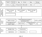
- FIG. 2 is a block diagram of a software structure of an electronic device 100 according to an embodiment of this application.
- software is divided into several layers, and each layer has a clear role and task.
- the layers communicate with each other through a software interface.
- the Android system is divided into four layers: an application layer, an application framework layer, an Android runtime (Android runtime) and system library, and a kernel layer from top to bottom.
- the application layer may include a series of application packages.
- the application packages may include applications such as "camera”, “gallery”, “calendar”, “calls”, “maps”, “navigation”, “WLAN”, “Bluetooth”, “music”, “videos”, and “messages”.
- the application framework layer provides an application programming interface (application programming interface, API) and a programming framework for an application at the application layer.
- the application framework layer includes some predefined functions.
- the application framework layer may include a display manager service (display manager service), an activity manager service (activity manager service), a window manager service (window manager service), and the like.
- display manager service display manager service
- activity manager service activity manager service
- window manager service window manager service
- the screen may be divided into a screen A and a screen B. It is assumed that the electronic device controls the screen A to be turned on to continue working, and the screen B is turned off for no work.
- the screen A may be turned on, and the user may perform a corresponding operation on the screen A.
- the screen B is turned off. Therefore, the user does not need to perform any operation on the screen B.
- the display management service is used to: after the electronic device detects an operation that the user triggers the screen A and the screen B to enter a cooperative working mode, adjust an actual display area of the screen to a size of the screen A and the screen B, so that another application interface can be displayed on the screen B.
- the activity management service is used to start the application interface on the screen B when the screen A and the screen B enter the cooperative working mode.
- the window management service is used to adjust positions of the application interfaces on the screen A and the screen B on the unfolded screen when the screen A and the screen B enter the cooperative working mode.
- the Android runtime includes a kernel library and a virtual machine.
- the Android runtime is responsible for scheduling and management of the Android system.
- the kernel library includes two parts: a function that needs to be invoked in java language and a kernel library of Android.
- the application layer and the application framework layer run on the virtual machine.
- the virtual machine executes java files at the application layer and the application framework layer as binary files.
- the virtual machine is configured to perform functions such as object lifecycle management, stack management, thread management, security and exception management, and garbage collection.
- the system library may include a plurality of function modules, for example, a surface manager (surface manager), a media library (media libraries), a three-dimensional graphics processing library (for example, OpenGL ES), and a 2D graphics engine (for example, SGL).
- a surface manager surface manager
- media libraries media libraries
- a three-dimensional graphics processing library for example, OpenGL ES
- 2D graphics engine for example, SGL
- the surface manager is configured to manage a display subsystem and provide fusion of 2D and 3D image layers for a plurality of applications.
- the media library supports playback and recording of a plurality of commonly used audio and video formats, static image files, and the like.
- the media library may support a plurality of audio and video coding formats such as MPEG-4, H.264, MP3, AAC, AMR, JPG, and PNG.
- the three-dimensional graphics processing library is configured to implement three-dimensional graphics drawing, image rendering, composition, layer processing, and the like.
- the 2D graphics engine is a drawing engine for 2D drawing.
- the kernel layer is a layer between hardware and software.
- the kernel layer includes at least a display driver, a camera driver, an audio driver, and a sensor driver.
- physical components related to the electronic device 100 mainly include hardware components such as a sensor, a decision support system (decision support systems, DSS) display chip, and a touchscreen, and application framework layer functions such as a display manager service, an activity manager service, and a window manager service.
- hardware components such as a sensor, a decision support system (decision support systems, DSS) display chip, and a touchscreen
- application framework layer functions such as a display manager service, an activity manager service, and a window manager service.
- the screen display control method provided in the embodiments of this application is mainly implemented by cooperation between a touch panel (touch panel, TP) module, one or more of the foregoing physical components, and layers of a software architecture layer of the electronic device 100.
- a touch panel touch panel, TP
- TP touch panel
- the foldable electronic device may include a primary screen, a side screen, and a sub screen.
- the primary screen and the sub screen may be folded by using the side screen as an axis.
- the folded state may be that the primary screen and the sub screen are folded in opposite directions, if the electronic device is in a non-lock screen state, the electronic device controls the primary screen to be turned on, and controls the sub screen to be turned off for no play.
- a total resolution of the foldable electronic device may be 2480*2200.
- the electronic device may be divided into the primary screen and the sub screen in a folded form.
- a resolution of the primary screen may be 2480*1144 (19.5:9).
- a resolution of the sub screen may be 2480*892 (25:9).
- a resolution of the side screen may be 2480*160.
- the display manager service may notify the LCD module of an area (for example, 2480*2200) that currently needs to be turned on, and the LCD module controls the entire touchscreen to be turned on.
- an area for example, 2480*2200
- the display manager service may notify the LCD module of an area (for example, 2480*1144) that currently needs to be turned on, and the LCD module controls the primary screen to be turned on, and controls the sub screen to be turned off and not to work.
- an area for example, 2480*1144
- the TP module may receive a tap operation of a user on the primary screen, and transfer the tap operation of the user to the display manager service at the application framework layer.
- the display manager service may notify the LCD module of an area that needs to be turned on, and the LCD module adjusts an actual display area of the touchscreen to a size of the entire touchscreen, so that an application interface may also be displayed on the sub screen.
- the activity manager service starts the application interface on the sub screen.
- the window manager service adjusts display locations of the application interface on the primary screen and the sub screen on the same unfolded touchscreen. Therefore, the primary screen and the sub screen enter a cooperative work mode.
- FIG. 1 and FIG. 2 the electronic device having the structures shown in FIG. 1 and FIG. 2 is used as an example to describe in detail the screen display control method provided in the embodiments of this application with reference to the accompanying drawings and application scenarios.
- a touchscreen of an electronic device is becoming larger.
- different screen display technologies are correspondingly developed.
- a user can simultaneously process a plurality of applications on the same touchscreen.
- flexible screens start to be widely used in electronic devices.
- a flexible screen has features of strong flexibility and bendability, can provide a user with a new interaction manner based on the bendability feature, and can meet more requirements of the user for an electronic device.
- the touchscreen on the electronic device may be switched between a small screen in a folded form and a large screen in an unfolded form at any time. Therefore, the user also uses a screen splitting function on the electronic device configured with the touchscreen more frequently.
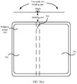
- FIG. 3(a) to FIG. 3(d) is a schematic diagram of an example of a foldable electronic device according to this application.
- FIG. 4 is a schematic diagram of division of a physical form of an example of a foldable electronic device according to an embodiment of this application. A touchscreen of the electronic device is first described with reference to FIG. 3(a) to FIG. 3(d) and FIG. 4 .
- a display area of the touchscreen 300 in a folded form may be divided into three areas: a first area 301, a second area 302, and a third area 303.
- FIG. 3(a) to FIG. 3(d) show at least three physical forms that may be included in the touchscreen 300 of the electronic device: the folded form, a half-folded form in which the touchscreen 300 is folded at a particular angle, and an unfolded form. As shown in FIG.
- a middle bending part shown by dotted line boundaries of the touchscreen 300 is the third area 303 described above, and with the third area 303 (or also referred to as a folded side screen) being used as an axis, the touchscreen 300 may be divided into the first area 301 (for example, an area on the right of the area 303 in FIG. 3(a) to FIG. 3(d) ) and the second area 302 (for example, an area on the left of the area 303 in FIG. 3(a) to FIG. 3(d) ).
- an angle between the first area 301 and the second area 302 may be a first angle ⁇ , where 0° ⁇ a 1 , and a 1 is less than or equal to 90 degrees and greater than or equal to 0 degrees.
- a 1 may be 25 degrees.
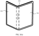
- FIG. 3(c) When the touchscreen 300 of the electronic device 100 is in a half-folded form in which the touchscreen 300 is folded at a particular angle, the touchscreen 300 may be shown in FIG. 3(c) .
- an angle between the first area 301 and the second area 302 is a second angle ⁇ , where a 1 ⁇ a 4 , a 1 is less than or equal to 90 degrees and greater than or equal to 0 degrees, and a 4 is greater than or equal to 90 degrees and less than 180 degrees.
- a 1 may be 25 degrees
- a 4 may be 155 degrees.
- the half-folded form of the touchscreen 300 may further include an unstable support state and a stable support state.
- an angle between the first area 301 and the second area 302 is a second angle ⁇
- a range of the second angle ⁇ is a 2 ⁇ a 3 , where a 2 is less than or equal to 90 degrees, and a 3 is greater than or equal to 90 degrees and less than 180 degrees.
- a form other than the stable support state is the unstable support state of the electronic device 100. It should be understood that division of physical forms of the touchscreen 300 and definitions of the physical forms are not limited in this application.
- the touchscreen 300 When the touchscreen 300 of the electronic device is in the unfolded form, the touchscreen 300 may be shown in FIG. 3(a) or FIG. 3(b) .
- an angle between the first area 301 and the second area 302 is a third angle ⁇ , where a 4 ⁇ 180 degrees, and a 4 is greater than or equal to 90 degrees and less than 180 degrees.
- a 4 may be 90 degrees.
- FIG. 3(a) shows a form when the third angle ⁇ is 180 degrees
- FIG. 3(b) shows a form in which the third angle ⁇ is greater than a 4 and less than 180 degrees.
- the foregoing provides only an example of classifying the electronic device into an unfolded form, a half-folded state, and a folded form.
- the entire touchscreen of the electronic device is working in a turned-on state.
- the display manager service may indicate the LCD module to turn on only the primary screen.
- a manner in which the electronic device determines that the electronic device is in the folded form is not limited in this embodiment of this application, and alternatively, the electronic device may determine, in another manner, that the electronic device is in the folded form.
- bending parts may alternatively be horizontally distributed in FIG. 3(a) , and the foldable screen may be folded up or down.
- the first area 301 and the second area 302 of the touchscreen may correspond to an upper end and a lower end of the middle bending part.
- This application is described by using the first area 301 and the second area 302 that are distributed left and right and that are shown in FIG. 3(a) as an example.
- the screen display control method provided in this application is also applicable to a manner in which the touchscreen is folded up or down. This is not limited in this application.
- the display mode herein may be understood as a display method of the foldable screen 300, for example, full screen display, a method in which display is performed in the first area 301 while the second area 302 is turned off, a method in which display is performed in the second area 302 while the first area 301 is turned off, or a method in which different interfaces are displayed in the first area 301 and the second area 302 simultaneously, or a plurality of other display modes.
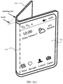
- FIG. 5(a) to FIG. 5(d) are schematic diagrams of a group of graphical user interfaces (graphical user interface, GUI) according to an embodiment of this application.
- a desktop of the electronic device may be displayed in the first area 301, and the second area 302 is turned off for no display.
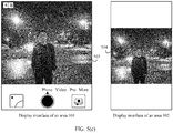
- the electronic device After detecting, in the first area 301, an operation of tapping an icon 501 of a camera by a user, the electronic device displays a GUI shown in FIG. 5(b) .
- the mobile phone may start the camera application, the GUI displayed in the first area 301 shown in FIG. 5(b) may be referred to as a photographing interface (or a camera interface).
- the photographing interface may include a preview window 503. In a preview state, an image captured by a camera may be displayed in the preview window 503 in real time.
- the electronic device displays the photographing interface in the first area 301, and the second area 302 is turned off for no display.
- the electronic device displays a GUI shown in FIG. 5(c) .
- the electronic device displays the photographing interface in the first area 301, displays a preview window 504 in the second area 302, and may also display, in the preview window 504, an image captured by the camera in real time for preview. This can help a photographed person adjust a posture of the photographed person in real time based on the image in the preview window 504 in the second area 302.
- the electronic device may further display the preview window 504 in the second area 302 after detecting a touch and hold operation of the user in the preview window 503 in the photographing interface.
- the electronic device displays the preview window 504 in the second area 302.
- the electronic device displays the photographing interface
- the electronic device detects a voice indication of the user
- the electronic device displays the preview window 504 in the second area 302.
- the electronic device may remind the user by using text in the photographing interface that reads "The primary screen and the sub screen simultaneously display the preview window", turn on the second area 302, and display the preview window 504 in the second area 302.
- the electronic device may remind the user by using text in the photographing interface that reads "Do you want the primary screen and the sub screen to simultaneously display the preview window?", and display a control 505 and a control 506.
- the electronic device After the electronic device detects an operation of tapping the control 505 by the user, the electronic device turns on the second area 302, and displays the preview window 504 in the second area 302.
- the electronic device enters a collaborative mode during photographing, that is, photographing preview windows may be displayed on a plurality of screens, thereby helping improve screen utilization.
- this can help a photographed object adjust a photographing posture in time, thereby helping improve user experience.
- the electronic device when detecting, in the photographing interface (or the camera interface), that the user taps a "video" control, the electronic device may enter a video photographing interface.
- the video photographing interface may include a preview window and a photographing control.
- the second area 302 is turned off for no display.
- the electronic device After detecting an operation of tapping the control 502 by the user, the electronic device may display the video photographing interface in the first area, and display the preview window of the video photographing interface in the second area.
- the electronic device when the electronic device is in the folded state, the electronic device may turn on the first area 301, and display the desktop of the electronic device in the first area 301, and the second area 302 is turned off for no display. After detecting, in the first area 301, an operation of tapping the camera icon 501 by the user, the electronic device may directly display the photographing interface in the first area 301, and display the preview window in the second area 302.
- the electronic device when entering the camera application in the folded form, may simultaneously display the photographing interface in the first area, and display the preview window in the second area. This helps improve screen utilization, and does not require a manual operation by a user, thereby helping improve user experience.
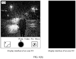
- the electronic device when the electronic device is in the folded form, displays the camera interface in the first area 301, and the second area 302 is turned off for no display. After detecting, in the first area 301, an operation of tapping the control 502 by the user, the electronic device may display the camera interface in the first area, and play an animation in the second area. In this way, during photographing of a child, attention of the child may be drawn, so that a photograph or a video that is satisfactory to the user is photographed.
- a user may tap the control 502 in the first area 301.
- the electronic device displays the GUI shown in FIG. 6(b) .
- the electronic device displays the photographing interface in the first area 301, and the second area 302 is turned off for no display.
- FIG. 7(a) to FIG. 7(c) show a group of GUIs in another scenario according to an embodiment of this application.
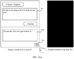
- a translation interface of a translation app is displayed in the first area 301, and a user may enter to-be-translated Chinese in an input box 701 in the first area 301.
- the user enters "Da rao yi xia, qing wen Ajiu dian zen me zou?” in the input box 701.
- a mobile phone detects that the user taps a "Translate” control
- a corresponding translation in English for example, "Excuse me, how can I get to hotel A?”
- the second area 302 is turned off for no display.
- the electronic device After detecting an operation of tapping a control 703 by the user, the electronic device displays a GUI shown in FIG. 7(b) .
- the translation interface continues to be displayed in the first area 301, and a corresponding translation in English may be displayed in the second area 302.
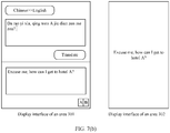
- the translation interface of the translation app may further include a control 704.
- a user may tap the control 704, and then modify the translation result in the output box 703.
- the electronic device may display a corresponding translation in English (for example, a translation result of the translation app is "Do you know the new wireless technology") in the output box 702.
- the "xin wu xian ji shu" is a technical term in the fifth generation mobile communications technology (5G), and should be translated as "new radio”.
- the user may modify the translation result.
- the electronic device may display the translation result considered to be accurate by the user in the second area. For example, "Do you know new radio?" may be displayed in the second area 302.
- the collaborative mode is entered, and translated content may be displayed in the second area, thereby helping improve screen utilization.
- this can improve efficiency of communication in a foreign language by the user, thereby improving user experience.
- FIG. 8(a) and FIG. 8(b) show another group of GUIs according to an embodiment of this application.
- the electronic device displays, in the first area 301, a bar code and a two-dimensional code that are used to pay a merchant, and the second area 302 is turned off for no display.
- the electronic device may display a GUI shown in FIG. 8(b) .
- the electronic device may display the barcode and the two-dimensional code in both the first area 301 and the second area 302.
- the barcode or the two-dimensional code may be displayed in the second area, thereby helping improve screen utilization.
- the user does not need to flip the electronic device, thereby facilitating scanning by a merchant, and helping improve user experience.
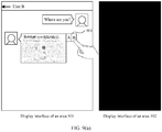
- FIG. 9(a) and FIG. 9(b) show another group of GUIs according to an embodiment of this application.
- the electronic device displays, in the first area 301, a chat interface of a user A and a user B, and the second area 302 is turned off for no display.
- the user A sends a message "Where are you?" to the user B, and the electronic device receives location information sent by the user B.
- the electronic device may display a GUI shown in FIG. 9(b) .
- the electronic device may display a chat interface of the user and another user in the first area 301, and open a map app in the second area 302 to display the location information.
- a user may further navigate in the map app displayed in the second area 302, so that the user can chat with another user on the chat app displayed in the first area 301, and view a route from a current location to a destination location on the map app displayed in the second area 302.
- a touchscreen When the foldable electronic device in a folded state, a touchscreen may include a primary screen, a side screen, and a sub screen, and a screen resolution of the primary screen may be greater than or equal to a screen resolution of the sub screen.
- FIG. 10(a) and FIG. 10(b) are a schematic diagram of a primary screen and a sub screen of an electronic device in an unfolded state and a folded state.
- FIG. 10(a) is a schematic diagram of the primary screen and the sub screen of the electronic device in the unfolded state.
- FIG. 10(b) is a schematic diagram of the primary screen and the sub screen of the electronic device in the folded state.
- FIG. 11(a) and FIG. 11(b) are a schematic diagram of display on a primary screen and a sub screen of an electronic device in a folded state.
- FIG. 11(a) shows that an application A may be displayed on the primary screen in the folded state, and the sub screen is turned off for no display.
- FIG. 11(b) is a schematic diagram of display on the primary screen and the sub screen that are viewed from an unfolded angle of the electronic device in the folded state.
- the application A is displayed on the primary screen.
- an available area of the screen is a size occupied by the primary screen.
- the sub screen is turned off for no display.
- the electronic device When the electronic device actively enters a collaborative mode by invoking an API provided by a system, or when the electronic device detects that a user taps a control in an interface of the application A on the primary screen, the electronic device performs, in response to the tap operation, the collaborative mode and displays an application B on the sub screen.
- FIG. 12(a) and FIG. 12(b) are another schematic diagram of display on a primary screen and a sub screen of an electronic device in a folded state.
- FIG. 12(a) is a schematic diagram of display on the primary screen and the sub screen that are viewed from an unfolded angle of the electronic device in the folded state.
- an application A is displayed on the primary screen
- an application B is displayed on the sub screen.
- an available area of a screen is a size of the screen that is unfolded.
- the electronic device needs to adjust a location of the application A to a location on a right side of the screen in an unfolded state, and the newly started application B is displayed at a location on a screen other than the primary screen and a side screen.
- the display service management module may notify the LCD module of an area that needs to be turned on, and an actual display area of the touchscreen is the entire touchscreen.
- the display management module may notify the LCD module of the area that needs to be turned on, and the LCD module adjusts the actual display area of the touchscreen to a size of the primary screen.
- the display management module may notify the LCD module of the area that needs to be turned on, and the LCD module adjusts the actual display area of the touchscreen to a size of the entire touchscreen.
- the side screen may be working but not displayed.
- a method for controlling, by the electronic device, the side screen to work but not to be displayed includes but is not limited to: covering, by the window manager service, the side screen by using a black background.
- a control (or a shortcut or the like) may be set on the side screen. After detecting an operation of tapping a control by the user in the third area, the electronic device turns on the third area (or the side screen).
- an available area of the screen of the electronic device is a screen B.
- a size of an available screen of the electronic device is a size of the entire screen unfolded.
- the window manager service may adjust a display location of the screen B on the same unfolded screen.
- coordinates of an upper left corner of the screen B in the entire screen may be (0, 0).
- the coordinates of the upper left corner of screen B in the entire screen may be (k, 0), where k may be a width of the screen A.
- horizontal coordinates of all points on the screen B are increased by k.
- FIG. 12(b) is a schematic diagram of display on the screen A and the screen B that are viewed from an unfolded angle of the electronic device in the folded state.
- the application B may be removed from the sub screen, and the sub screen is turned off for no display.
- screen utilization can be improved in the folded state, more content can be displayed, and additional interface content can be displayed without covering current screen content, thereby helping improve user experience.
- GUIs for cooperative work between the first area and the second area of the electronic device in the folded form are described.
- one gyroscope sensor may be deployed in each of the first area and the second area.
- the electronic device may obtain the angle between the first area and the second area through measurement by using the gyroscope sensors deployed in the first area and the second area.
- FIG. 13 is a schematic diagram of another example of a foldable electronic device according to an embodiment of this application.
- the electronic device detects that a user folds the electronic device towards a direction in which a screen A and a screen B face each other.
- Directions of the screen A and the screen B are respectively z 1 and z 2
- an angle ⁇ at which the foldable electronic device is folded is an angle between z 1 and z 2 .
- the direction of z1 may be determined by using a gyroscope sensor deployed on the screen A, and the direction of z2 may be determined by using a gyroscope sensor deployed on the screen B, to finally obtain an angle ⁇ between z1 and z2.
- a coordinate system of the gyroscope sensor is a geographic coordinate system: The gyroscope sensor is used as an origin, a direction due east is an x-axis direction, a direction due north is a y-axis direction, and a direction opposite to an earth plumb line is a z-axis direction.
- FIG. 14 is a schematic diagram of another example of a foldable electronic device according to an embodiment of this application.
- Coordinate systems of gyroscope sensors on a screen A and a screen B are respectively Xi-Yi-Zi and X 2 -Y 2 -Z 2 .
- origins of the gyroscope sensors in the screen A and the screen B do not overlap, X, Y, and Z axes of the two coordinate systems may be considered parallel. Therefore, the gyroscope coordinate systems in the screen A and the screen B may be considered parallel.
- the angle ⁇ at which the foldable electronic device is folded may be determined as follows:
- Step 1 Obtain vector data of directions of the screen A and the screen B, where a direction of the screen A is represented by using a vector z 1 , and a direction of the screen B may be represented by using a vector z 2 .
- data of the vector z 1 is (0, 0, a)
- data of the vector z 2 is (0, b, c).
- the data of the vector z 1 and the data of the vector z 2 may be obtained by the gyroscope sensors.
- Step 2 Calculate an angle ⁇ between the directions of the screen A and the screen B.
- the angle formed between z 1 and z 2 is ⁇ .
- one acceleration sensor and one gravity sensor may be deployed in the first area, and one acceleration sensor and one gravity sensor may be deployed in the second area.
- the electronic device may determine, by using the acceleration sensors and the gravity sensors deployed in the first area and the second area, whether the first area and the second area are folded opposite to each other or facing each other, and may obtain the angle between the first area and the second area through measurement.
- the electronic device may be folded only in a method in which the first area and the second area are opposite to each other, or may be folded in either a method in which the first area and the second area are opposite to each other or a direction in which the first area and the second area face each other.
- an angle sensor may be deployed in a third area (side screen).
- a direction in which the electronic device is folded may be detected by using the angle sensor.
- an embodiment of this application provides a screen display control method.
- the method may be implemented in the electronic device (for example, a mobile phone or a tablet computer) having a foldable touchscreen shown in FIG. 1 and FIG. 2 .
- the method may include the following steps.
- S1501 The electronic device displays a first interface in the first area.
- the electronic device displays a photographing interface (or a camera interface) in the area 301.
- the electronic device displays a translation interface in the area 301.
- the electronic device displays a payment interface in the area 301.
- the electronic device displays, in the area 301, a chat interface with a user B.
- S1502 The electronic device detects a first operation in the first interface.
- the first operation may be that the electronic device detects, in the camera interface, an operation of tapping the control 502 by a user.
- the first operation may be that the electronic device detects, in the translation interface, an operation of tapping the control 703 by a user.
- the first operation may be that the electronic device detects, in the payment interface, an operation of tapping the control 801 by a user.
- the first operation may be that the electronic device detects, in the chat interface, an operation of tapping the control 901 by a user.
- the first operation may further be a touch and hold operation, a pressing operation, a voice indication operation, or the like detected by the electronic device in the foregoing interfaces.
- S1503 Display a second interface in the second area in response to the first operation, where the second interface is associated with content displayed in the first interface.
- the electronic device may display the preview window 504 in the second area 302.
- Content displayed in the preview window 504 may be the same as image information displayed in the preview window 503 in the first area 503.
- a part of image information in the preview window 503 may be displayed in the preview window 504.
- an aspect ratio displayed on the preview window 503 is 4:3.
- An aspect ratio displayed in the preview window 504 is 4:3, or an aspect ratio displayed in the preview window 504 is 3:3.
- the electronic device may display, in the area 302, a translation result of to-be-translated content in the area 301.
- the electronic device may display, in the area 302, a payment code in the area 301.
- the payment code may include a bar code and/or a two-dimensional code.
- the electronic device may display, in the area 302, a map display interface of a map app, and the map display interface may display detailed location information in the area 301.
- that the electronic device displays a first interface in the first area includes:
- the electronic device determines that the electronic device is in a folded form.
- the electronic device displays the first area in the first area in response to being in the folded form, and the electronic device turns off the second area.
- the electronic device when the electronic device is in the folded form, the electronic device displays the camera interface in the area 301, and the area 302 is turned off for no display.
- the electronic device when the electronic device is in the folded form, the electronic device displays the translation interface in the area 301, and the area 302 is turned off for no display.
- the electronic device when the electronic device is in the folded form, the electronic device displays the payment interface in the area 301, and the area 302 is turned off for no display.
- the electronic device when the electronic device is in the folded form, the electronic device displays the chat interface in the area 301, and the area 302 is turned off for no display.
- the method further includes:
- the electronic device detects a second operation in the first interface.
- the electronic device turns off the second area in response to the second operation.
- the second operation may be an operation of tapping the control 502 by the user that is detected by the electronic device.
- the electronic device turns off the area 302.
- the electronic device includes corresponding hardware and/or software modules for performing the functions.
- Algorithm steps in the examples described with reference to the embodiments disclosed in this specification can be implemented by hardware or a combination of hardware and computer software in this application. Whether a function is performed by hardware or by computer software driving hardware depends on specific applications and design constraints of the technical solution. A person skilled in the art may use different methods to implement the described functions for each specific application with reference to the embodiments, but it should not be considered that such implementation goes beyond the scope of this application.
- the electronic device may be divided into function modules based on the foregoing method examples.
- each function module may be obtained through division corresponding to each function, or two or more functions may be integrated into one processing module.
- the integrated module may be implemented in a form of hardware. It should be noted that, division into modules in this embodiment is an example, and is merely logical function division. In actual implementation, there may be another division manner.
- FIG. 16 is a possible schematic composition diagram of the electronic device 1600 in the foregoing embodiment.
- the electronic device 1600 may include a display unit 1601 and a detection unit 1602.
- the display unit 1601 may be configured to support the electronic device 1600 in performing step 1501, step 1503, and the like, and/or is configured to perform another process of the technology described in this specification.
- the detection unit 1602 may be configured to support the electronic device 1600 in performing the foregoing step 1502 and the like, and/or is configured to perform another process of the technology described in this specification.
- the electronic device provided in this embodiment is configured to execute the foregoing screen display control method, and therefore can achieve a same effect as the foregoing implementation method.
- the electronic device may include a processing module, a storage module, and a communications module.
- the processing module may be configured to control and manage an action of the electronic device, for example, may be configured to support the electronic device in performing steps performed by the display unit 1601 and the detection unit 1603.
- the storage module may be configured to support the electronic device in executing storage program code, data, and the like.
- the communications module may be configured to support communication between the electronic device and another device.
- the processing module may be a processor or a controller.
- the apparatus may implement or execute various example logical blocks, modules, and circuits described with reference to content disclosed in this application.
- the processor may also be a combination of implementing a computing function, for example, a combination of one or more microprocessors (digital signal processing DSP) and a microprocessor.
- the storage module may be a memory.
- the communications module may be specifically a device that interacts with another electronic device, such as a radio frequency circuit, a Bluetooth chip, or a Wi-Fi chip.
- the electronic device in this embodiment may be a device having a structure shown in FIG. 1 .
- This embodiment further provides a computer storage medium.
- the computer storage medium stores computer instructions.
- the computer instruction runs on an electronic device, the electronic device is enabled to perform the foregoing related method steps to implement the screen display control method in the foregoing embodiment.
- This embodiment further provides a computer program product.
- the computer program product When the computer program product is run on a computer, the computer is enabled to perform the foregoing related steps, so as to implement the screen display control method in the foregoing embodiment.
- an embodiment of this application further provides an apparatus.
- the apparatus may be specifically a chip, a component, or a module, and the apparatus may include a processor and a memory that are connected.
- the memory is configured to store computer-executable instructions.
- the processor may execute the computer-executable instructions stored in the memory, so that the chip performs the screen display control method in the foregoing method embodiments.
- the electronic device, the computer storage medium, the computer program product, or the chip provided in the embodiments are all configured to perform the corresponding method provided above. Therefore, for beneficial effects that can be achieved by the electronic device, the computer storage medium, the computer program product, or the chip, refer to beneficial effects in the corresponding method provided above. Details are not described herein again.
- the disclosed apparatus and method may be implemented in other manners.
- the described apparatus embodiment is merely an example.
- the division into modules or units is merely logical function division and may be other division in actual implementation.
- a plurality of units or components may be combined or integrated into another apparatus, or some features may be ignored or not performed.
- the displayed or discussed mutual couplings or direct couplings or communication connections may be implemented by using some interfaces, and the indirect couplings or communication connections between the apparatuses or units may be implemented in electrical, mechanical, or other forms.
- the units described as separate parts may or may not be physically separate, and parts displayed as units may be one or more physical units, that is, may be located in one place, or may be distributed in a plurality of different places. Some or all of the units may be selected according to actual requirements to achieve the objectives of the solutions of the embodiments.
- functional units in the embodiments of this application may be integrated into one processing unit, or each of the units may exist alone physically, or two or more units may be integrated into one unit.
- the integrated unit may be implemented in a form of hardware, or may be implemented in a form of a software functional unit.
- the integrated unit When an integrated unit is implemented in a form of a software functional unit and sold or used as an independent product, the integrated unit may be stored in a readable storage medium.
- the technical solutions in the embodiments of this application may be essentially, a part that contributes to the prior art, or all or part of the technical solutions may be embodied in a form of a software product.
- the software product is stored in a storage medium, and includes several instructions to enable a device (which may be a single-chip microcomputer, a chip, or the like). or a processor (processor) performs all or some steps of the methods in the embodiments of this application.
- the foregoing storage medium includes any medium that can store program code, such as a USB flash drive, a removable hard disk, a read only memory (read only memory, ROM), a random access memory (random access memory, RAM), a magnetic disk, or an optical disc.
- program code such as a USB flash drive, a removable hard disk, a read only memory (read only memory, ROM), a random access memory (random access memory, RAM), a magnetic disk, or an optical disc.
Landscapes
- Engineering & Computer Science (AREA)
- Theoretical Computer Science (AREA)
- General Engineering & Computer Science (AREA)
- Physics & Mathematics (AREA)
- General Physics & Mathematics (AREA)
- Human Computer Interaction (AREA)
- Computer Hardware Design (AREA)
- Business, Economics & Management (AREA)
- Accounting & Taxation (AREA)
- Strategic Management (AREA)
- General Business, Economics & Management (AREA)
- Health & Medical Sciences (AREA)
- Artificial Intelligence (AREA)
- Audiology, Speech & Language Pathology (AREA)
- Computational Linguistics (AREA)
- General Health & Medical Sciences (AREA)
- Finance (AREA)
- Computer Networks & Wireless Communication (AREA)
- Development Economics (AREA)
- Economics (AREA)
- Signal Processing (AREA)
- Mathematical Physics (AREA)
- Computing Systems (AREA)
- User Interface Of Digital Computer (AREA)
- Controls And Circuits For Display Device (AREA)
Applications Claiming Priority (2)
| Application Number | Priority Date | Filing Date | Title |
|---|---|---|---|
| CN201910134248.XA CN109917956B (zh) | 2019-02-22 | 2019-02-22 | 一种控制屏幕显示的方法和电子设备 |
| PCT/CN2020/075034 WO2020168970A1 (fr) | 2019-02-22 | 2020-02-13 | Procédé de commande d'affichage d'écran et dispositif électronique |
Publications (2)
| Publication Number | Publication Date |
|---|---|
| EP3920008A1 true EP3920008A1 (fr) | 2021-12-08 |
| EP3920008A4 EP3920008A4 (fr) | 2022-04-27 |
Family
ID=66962124
Family Applications (1)
| Application Number | Title | Priority Date | Filing Date |
|---|---|---|---|
| EP20759539.8A Ceased EP3920008A4 (fr) | 2019-02-22 | 2020-02-13 | Procédé de commande d'affichage d'écran et dispositif électronique |
Country Status (6)
| Country | Link |
|---|---|
| US (2) | US11630577B2 (fr) |
| EP (1) | EP3920008A4 (fr) |
| KR (1) | KR102576844B1 (fr) |
| CN (4) | CN109917956B (fr) |
| BR (1) | BR112021016461A2 (fr) |
| WO (1) | WO2020168970A1 (fr) |
Cited By (2)
| Publication number | Priority date | Publication date | Assignee | Title |
|---|---|---|---|---|
| EP4506931A4 (fr) * | 2023-06-12 | 2025-08-13 | Samsung Electronics Co Ltd | Dispositif électronique pour détecter un dysfonctionnement à l'aide d'un capteur d'éclairage, et procédé de commande associé |
| EP4661414A4 (fr) * | 2023-07-12 | 2026-01-07 | Honor Device Co Ltd | Procédé de photographie et dispositif électronique |
Families Citing this family (61)
| Publication number | Priority date | Publication date | Assignee | Title |
|---|---|---|---|---|
| CN109917956B (zh) | 2019-02-22 | 2021-08-03 | 华为技术有限公司 | 一种控制屏幕显示的方法和电子设备 |
| KR102839990B1 (ko) * | 2019-04-17 | 2025-07-29 | 삼성전자 주식회사 | 화면의 빠른 전환을 수행하는 전자 장치 및 전자 장치의 동작 방법 |
| CN110401766B (zh) | 2019-05-22 | 2021-12-21 | 华为技术有限公司 | 一种拍摄方法及终端 |
| CN110456951B (zh) * | 2019-06-26 | 2021-10-26 | 华为技术有限公司 | 一种应用显示方法及电子设备 |
| JP7238642B2 (ja) * | 2019-06-28 | 2023-03-14 | セイコーエプソン株式会社 | 表示装置および表示制御プログラム |
| CN110399086B (zh) * | 2019-07-24 | 2021-09-24 | 网易(杭州)网络有限公司 | 游戏画面的显示控制方法、装置、存储介质和电子设备 |
| CN114816620A (zh) | 2019-07-29 | 2022-07-29 | 华为技术有限公司 | 一种显示方法及电子设备 |
| CN110381282B (zh) | 2019-07-30 | 2021-06-29 | 华为技术有限公司 | 一种应用于电子设备的视频通话的显示方法及相关装置 |
| CN110602273B (zh) * | 2019-08-05 | 2021-06-08 | 华为技术有限公司 | 一种消息显示方法、电子设备及计算机可读存储介质 |
| CN110661917B (zh) * | 2019-08-07 | 2022-04-12 | 华为技术有限公司 | 一种显示方法及电子设备 |
| CN110597510B (zh) * | 2019-08-09 | 2021-08-20 | 华为技术有限公司 | 一种界面的动态布局方法及设备 |
| CN110620833B (zh) * | 2019-08-16 | 2021-05-11 | 华为技术有限公司 | 一种可折叠的电子设备的显示方法及电子设备 |
| CN114006625B (zh) * | 2019-08-26 | 2023-03-28 | 华为技术有限公司 | 一种分屏显示方法与电子设备 |
| CN115297199B (zh) * | 2019-08-30 | 2025-02-14 | 华为技术有限公司 | 一种具有折叠屏的设备的触控方法与折叠屏设备 |
| CN110830645B (zh) * | 2019-09-24 | 2021-05-18 | 华为技术有限公司 | 一种操作方法和电子设备及计算机存储介质 |
| CN112583957A (zh) * | 2019-09-30 | 2021-03-30 | 华为技术有限公司 | 电子设备的显示方法、电子设备与计算机可读存储介质 |
| CN112671976B (zh) | 2019-09-30 | 2023-01-13 | 华为技术有限公司 | 电子设备的控制方法、装置及电子设备、存储介质 |
| CN112671969B (zh) * | 2019-10-16 | 2022-06-10 | 珠海金山办公软件有限公司 | 一种终端显示调节方法、装置和终端 |
| CN112698684B (zh) * | 2019-10-22 | 2024-05-28 | 北京小米移动软件有限公司 | 屏幕显示装置、屏幕显示控制方法、屏幕显示控制装置及存储介质 |
| CN110769153B (zh) * | 2019-10-29 | 2021-04-06 | 维沃移动通信有限公司 | 一种图像处理方法及电子设备 |
| CN110825474B (zh) * | 2019-10-31 | 2023-03-31 | 维沃移动通信有限公司 | 界面显示方法、装置和电子设备 |
| CN111124561B (zh) * | 2019-11-08 | 2021-02-12 | 华为技术有限公司 | 应用于具有折叠屏的电子设备的显示方法及电子设备 |
| CN111176539A (zh) * | 2019-11-11 | 2020-05-19 | 广东小天才科技有限公司 | 一种分屏显示方法及终端设备 |
| CN110888616B (zh) * | 2019-11-18 | 2024-01-26 | 中国联合网络通信集团有限公司 | 信息显示方法、装置和存储介质 |
| CN111049973B (zh) * | 2019-11-22 | 2021-06-01 | 维沃移动通信有限公司 | 一种屏幕显示的控制方法、电子设备及计算机可读存储介质 |
| CN111190563A (zh) * | 2019-12-31 | 2020-05-22 | 华为技术有限公司 | 界面显示方法及相关装置 |
| CN111064896A (zh) * | 2019-12-31 | 2020-04-24 | 维沃移动通信有限公司 | 设备控制方法及电子设备 |
| CN111262975B (zh) * | 2020-01-08 | 2021-06-08 | 华为技术有限公司 | 亮屏控制方法、电子设备、计算机可读存储介质和程序产品 |
| CN111475077A (zh) * | 2020-02-04 | 2020-07-31 | 华为技术有限公司 | 显示控制方法及电子设备 |
| CN111885285B (zh) * | 2020-06-29 | 2021-11-23 | 维沃移动通信(杭州)有限公司 | 图像拍摄方法及电子设备 |
| CN112698896B (zh) * | 2020-12-25 | 2024-05-31 | 维沃移动通信有限公司 | 文本显示方法和电子设备 |
| US11720312B2 (en) * | 2021-03-22 | 2023-08-08 | Motorola Mobility Llc | Manage quickview content for a multi-display device |
| CN113342293B (zh) * | 2021-05-21 | 2022-07-08 | 亿咖通(湖北)技术有限公司 | 信息显示方法与装置 |
| CN113741781B (zh) | 2021-06-15 | 2022-06-28 | 荣耀终端有限公司 | 通知显示方法和电子设备 |
| CN115826902A (zh) * | 2021-07-12 | 2023-03-21 | 荣耀终端有限公司 | 显示方法、介质、程序产品、芯片装置和电子设备 |
| CN116346976B (zh) * | 2021-12-22 | 2026-01-09 | 华为技术有限公司 | 一种多屏的解锁方法和电子设备 |
| CN116339881A (zh) * | 2021-12-22 | 2023-06-27 | 华为技术有限公司 | 内容显示方法、电子设备及计算机可读存储介质 |
| CN116339568B (zh) | 2021-12-25 | 2024-11-08 | 荣耀终端有限公司 | 屏幕显示方法和电子设备 |
| WO2023124129A1 (fr) | 2021-12-28 | 2023-07-06 | 荣耀终端有限公司 | Procédé d'affichage de code bidimensionnel et dispositif électronique |
| CN116415951B (zh) * | 2021-12-28 | 2024-06-07 | 荣耀终端有限公司 | 显示二维码的方法和电子设备 |
| CN116437194B (zh) * | 2021-12-31 | 2024-04-05 | 荣耀终端有限公司 | 显示预览图像的方法、装置及可读存储介质 |
| CN114398016B (zh) * | 2022-01-12 | 2024-06-11 | 金华鸿正科技有限公司 | 界面显示方法和装置 |
| CN114531610B (zh) * | 2022-02-25 | 2023-03-24 | 深圳沃顿科技有限公司 | 用于显示屏的拼接显示方法、装置、设备及存储介质 |
| CN114598815B (zh) * | 2022-03-02 | 2024-01-05 | 北京字跳网络技术有限公司 | 一种拍摄方法、装置、电子设备和存储介质 |
| CN114401373B (zh) * | 2022-03-24 | 2022-09-02 | 荣耀终端有限公司 | 双屏同显的方法、电子设备及可读存储介质 |
| EP4496300A4 (fr) | 2022-04-19 | 2025-06-18 | Samsung Electronics Co., Ltd | Dispositif électronique comprenant un dispositif d'affichage flexible, et procédé de fonctionnement associé |
| CN114741042A (zh) * | 2022-04-27 | 2022-07-12 | 维沃移动通信有限公司 | 内容显示方法及装置 |
| CN115079983A (zh) * | 2022-06-30 | 2022-09-20 | 深圳传音控股股份有限公司 | 显示方法、智能终端及存储介质 |
| CN115079982A (zh) * | 2022-06-30 | 2022-09-20 | 深圳传音控股股份有限公司 | 控制方法、智能终端及存储介质 |
| CN115202788A (zh) * | 2022-07-18 | 2022-10-18 | 深圳高通半导体有限公司 | 多界面显示设备及其显示控制方法 |
| KR20240021045A (ko) * | 2022-08-09 | 2024-02-16 | 삼성전자주식회사 | 복수의 디스플레이들을 통해 화면을 표시하기 위한 전자 장치 및 방법 |
| CN116048686B (zh) * | 2022-08-29 | 2023-11-24 | 荣耀终端有限公司 | 显示方法及折叠屏设备 |
| CN115509479A (zh) * | 2022-09-26 | 2022-12-23 | 联想(北京)有限公司 | 一种显示控制方法及装置 |
| CN118276724A (zh) * | 2022-12-29 | 2024-07-02 | 华为技术有限公司 | 一种显示方法以及电子设备 |
| CN117119276B (zh) * | 2023-04-21 | 2024-08-09 | 荣耀终端有限公司 | 一种水下拍摄方法及电子设备 |
| WO2025005678A1 (fr) * | 2023-06-27 | 2025-01-02 | 삼성전자 주식회사 | Dispositif électronique et procédé de paiement par gestes l'utilisant |
| CN119225567A (zh) * | 2023-06-30 | 2024-12-31 | 华为技术有限公司 | 一种界面显示方法和电子设备 |
| CN119271027A (zh) * | 2023-07-05 | 2025-01-07 | 华为技术有限公司 | 一种控制方法、控制电路和电子设备 |
| CN117615055B (zh) * | 2023-09-19 | 2024-11-01 | 荣耀终端有限公司 | 一种显示控制方法、电子设备及存储介质 |
| WO2025059881A1 (fr) * | 2023-09-19 | 2025-03-27 | 荣耀终端股份有限公司 | Procédé d'affichage et dispositif électronique |
| CN119718229B (zh) * | 2023-09-19 | 2026-04-24 | 荣耀终端股份有限公司 | 壁纸切屏显示方法、设备及存储介质 |
Family Cites Families (32)
| Publication number | Priority date | Publication date | Assignee | Title |
|---|---|---|---|---|
| US7782274B2 (en) | 2006-06-09 | 2010-08-24 | Cfph, Llc | Folding multimedia display device |
| RU84613U1 (ru) | 2009-03-04 | 2009-07-10 | Юрий Константинович Низиенко | Складной дисплей |
| KR101560718B1 (ko) * | 2009-05-29 | 2015-10-15 | 엘지전자 주식회사 | 이동 단말기 및 이동 단말기에서의 정보 표시 방법 |
| KR101727894B1 (ko) * | 2010-05-06 | 2017-04-18 | 엘지전자 주식회사 | 휴대 단말기 및 그 동작 제어방법 |
| US9606723B2 (en) * | 2011-07-21 | 2017-03-28 | Z124 | Second view |
| KR101990036B1 (ko) * | 2012-10-31 | 2019-06-17 | 엘지전자 주식회사 | 이동 단말기 및 그것의 제어 방법 |
| KR102097361B1 (ko) * | 2013-02-01 | 2020-04-07 | 삼성디스플레이 주식회사 | 가요성 디스플레이 장치를 구비한 모바일 기기 및 이의 동작 방법 |
| KR101526046B1 (ko) * | 2013-04-05 | 2015-06-05 | 문중식 | 바코드를 제공하는 전자 디바이스 및 바코드 제공 방법 |
| KR20150014807A (ko) * | 2013-07-30 | 2015-02-09 | 엘지전자 주식회사 | 이동 단말기 및 이동 단말기의 제어 방법 |
| US10089346B2 (en) * | 2014-04-25 | 2018-10-02 | Dropbox, Inc. | Techniques for collapsing views of content items in a graphical user interface |
| KR101632008B1 (ko) * | 2014-04-30 | 2016-07-01 | 엘지전자 주식회사 | 이동단말기 및 그 제어방법 |
| KR101609184B1 (ko) * | 2014-05-27 | 2016-04-06 | 네이버 주식회사 | 사전 기능을 제공하는 방법과 시스템, 그리고 기록 매체 및 파일 배포 시스템 |
| CN104571857A (zh) * | 2014-12-18 | 2015-04-29 | 惠州Tcl移动通信有限公司 | 一种自定义触摸的定制方法、响应方法及移动终端 |
| US10254863B2 (en) * | 2014-12-19 | 2019-04-09 | Lg Electronics Inc. | Mobile terminal |
| CN105224273B (zh) | 2015-09-25 | 2018-08-31 | 联想(北京)有限公司 | 显示处理方法、显示处理装置和电子设备 |
| US10061346B2 (en) * | 2015-10-22 | 2018-08-28 | Dell Products L.P. | Folded continuous multielement touch display |
| KR20170056841A (ko) * | 2015-11-16 | 2017-05-24 | 엘지전자 주식회사 | 이동 단말기 및 이동 단말기의 제어 방법 |
| KR102578982B1 (ko) * | 2015-11-30 | 2023-09-18 | 삼성전자주식회사 | 번역 서비스를 제공하는 방법 및 이를 위한 전자 장치 |
| JP2017211925A (ja) * | 2016-05-27 | 2017-11-30 | レノボ・シンガポール・プライベート・リミテッド | 情報処理装置及び画像表示方法 |
| KR102701604B1 (ko) * | 2017-02-23 | 2024-09-03 | 삼성전자주식회사 | 아웃 폴딩(out-foldable) 가능한 전자 장치 및 아웃 폴딩 가능한 전자 장치의 제어방법 |
| CN110462556B (zh) | 2017-04-20 | 2022-06-10 | 华为技术有限公司 | 显示控制方法及装置 |
| CN107645611A (zh) * | 2017-10-17 | 2018-01-30 | 维沃移动通信有限公司 | 一种支付方法及移动终端 |
| CN107766114A (zh) * | 2017-10-19 | 2018-03-06 | 广东欧珀移动通信有限公司 | 显示商品信息的方法和装置 |
| CN108008889A (zh) * | 2017-11-30 | 2018-05-08 | 努比亚技术有限公司 | 柔性屏的拍照方法、移动终端及计算机可读存储介质 |
| CN108076292A (zh) * | 2017-12-28 | 2018-05-25 | 努比亚技术有限公司 | 拍摄方法、移动终端及存储介质 |
| CN108227996B (zh) * | 2018-01-24 | 2020-10-16 | 维沃移动通信有限公司 | 一种显示控制方法及移动终端 |
| CN108566458A (zh) * | 2018-03-28 | 2018-09-21 | 京东方科技集团股份有限公司 | 一种折叠式显示装置及其控制方法 |
| CN108234891B (zh) | 2018-04-04 | 2019-11-05 | 维沃移动通信有限公司 | 一种拍照方法及移动终端 |
| CN109144351A (zh) * | 2018-07-05 | 2019-01-04 | Oppo(重庆)智能科技有限公司 | 终端设备及其控制方法、控制组件和可读存储介质 |
| CN109101149A (zh) * | 2018-07-17 | 2018-12-28 | 维沃移动通信有限公司 | 一种应用图标管理方法及终端 |
| CN109246360B (zh) * | 2018-11-23 | 2021-01-26 | 维沃移动通信(杭州)有限公司 | 一种提示方法及移动终端 |
| CN109917956B (zh) | 2019-02-22 | 2021-08-03 | 华为技术有限公司 | 一种控制屏幕显示的方法和电子设备 |
-
2019
- 2019-02-22 CN CN201910134248.XA patent/CN109917956B/zh active Active
-
2020
- 2020-02-13 EP EP20759539.8A patent/EP3920008A4/fr not_active Ceased
- 2020-02-13 CN CN202111122176.0A patent/CN114115587A/zh active Pending
- 2020-02-13 KR KR1020217029925A patent/KR102576844B1/ko active Active
- 2020-02-13 CN CN202411563479.XA patent/CN119806345A/zh active Pending
- 2020-02-13 WO PCT/CN2020/075034 patent/WO2020168970A1/fr not_active Ceased
- 2020-02-13 BR BR112021016461-8A patent/BR112021016461A2/pt unknown
- 2020-02-13 CN CN202080015660.0A patent/CN113518967B/zh active Active
-
2021
- 2021-08-23 US US17/409,604 patent/US11630577B2/en active Active
-
2023
- 2023-03-16 US US18/184,861 patent/US11829599B2/en active Active
Cited By (2)
| Publication number | Priority date | Publication date | Assignee | Title |
|---|---|---|---|---|
| EP4506931A4 (fr) * | 2023-06-12 | 2025-08-13 | Samsung Electronics Co Ltd | Dispositif électronique pour détecter un dysfonctionnement à l'aide d'un capteur d'éclairage, et procédé de commande associé |
| EP4661414A4 (fr) * | 2023-07-12 | 2026-01-07 | Honor Device Co Ltd | Procédé de photographie et dispositif électronique |
Also Published As
| Publication number | Publication date |
|---|---|
| KR20210130185A (ko) | 2021-10-29 |
| US11630577B2 (en) | 2023-04-18 |
| CN113518967B (zh) | 2024-11-22 |
| BR112021016461A2 (pt) | 2021-10-13 |
| CN119806345A (zh) | 2025-04-11 |
| EP3920008A4 (fr) | 2022-04-27 |
| US20230221861A1 (en) | 2023-07-13 |
| KR102576844B1 (ko) | 2023-09-08 |
| CN109917956A (zh) | 2019-06-21 |
| WO2020168970A1 (fr) | 2020-08-27 |
| CN113518967A (zh) | 2021-10-19 |
| US20210389873A1 (en) | 2021-12-16 |
| CN109917956B (zh) | 2021-08-03 |
| CN114115587A (zh) | 2022-03-01 |
| US11829599B2 (en) | 2023-11-28 |
Similar Documents
| Publication | Publication Date | Title |
|---|---|---|
| US11829599B2 (en) | Screen display control method and electronic device | |
| US12335601B2 (en) | Image capture method, graphic user interface, and electronic device | |
| US12254174B2 (en) | Method and device for displaying two application interfaces in folded and unfolded states of the device | |
| US12333202B2 (en) | Foldable screen display method and electronic device | |
| EP4181494B1 (fr) | Méthode d'affichage, appareil associé et support de stockage lisible par ordinateur | |
| US12449960B2 (en) | Interface display method and device | |
| US20250272119A1 (en) | User interface layout method and electronic device | |
| CN112714901B (zh) | 系统导航栏的显示控制方法、图形用户界面及电子设备 | |
| US12511006B2 (en) | Method for sharing input device, electronic device, and system | |
| US12106007B2 (en) | Collaborative display method, terminal device, and computer-readable storage medium | |
| CN116048350B (zh) | 一种截屏方法及电子设备 | |
| CN114661190B (zh) | 终端窗口显示方法、终端和存储介质 | |
| US20240143262A1 (en) | Splicing Display Method, Electronic Device, and System | |
| RU2781566C1 (ru) | Способ управления отображением на экране и электронное устройство |
Legal Events
| Date | Code | Title | Description |
|---|---|---|---|
| STAA | Information on the status of an ep patent application or granted ep patent |
Free format text: STATUS: THE INTERNATIONAL PUBLICATION HAS BEEN MADE |
|
| PUAI | Public reference made under article 153(3) epc to a published international application that has entered the european phase |
Free format text: ORIGINAL CODE: 0009012 |
|
| STAA | Information on the status of an ep patent application or granted ep patent |
Free format text: STATUS: REQUEST FOR EXAMINATION WAS MADE |
|
| 17P | Request for examination filed |
Effective date: 20210903 |
|
| AK | Designated contracting states |
Kind code of ref document: A1 Designated state(s): AL AT BE BG CH CY CZ DE DK EE ES FI FR GB GR HR HU IE IS IT LI LT LU LV MC MK MT NL NO PL PT RO RS SE SI SK SM TR |
|
| REG | Reference to a national code |
Ref country code: DE Ref legal event code: R079 Free format text: PREVIOUS MAIN CLASS: G06F0003041000 Ipc: G06F0003048800 |
|
| A4 | Supplementary search report drawn up and despatched |
Effective date: 20220324 |
|
| RIC1 | Information provided on ipc code assigned before grant |
Ipc: G06F 1/16 20060101ALN20220319BHEP Ipc: G06F 3/0487 20130101ALI20220319BHEP Ipc: G06F 3/0488 20130101AFI20220319BHEP |
|
| DAV | Request for validation of the european patent (deleted) | ||
| DAX | Request for extension of the european patent (deleted) | ||
| STAA | Information on the status of an ep patent application or granted ep patent |
Free format text: STATUS: EXAMINATION IS IN PROGRESS |
|
| 17Q | First examination report despatched |
Effective date: 20230111 |
|
| APBK | Appeal reference recorded |
Free format text: ORIGINAL CODE: EPIDOSNREFNE |
|
| APBN | Date of receipt of notice of appeal recorded |
Free format text: ORIGINAL CODE: EPIDOSNNOA2E |
|
| APBR | Date of receipt of statement of grounds of appeal recorded |
Free format text: ORIGINAL CODE: EPIDOSNNOA3E |
|
| APAF | Appeal reference modified |
Free format text: ORIGINAL CODE: EPIDOSCREFNE |
|
| REG | Reference to a national code |
Ref country code: DE Ref legal event code: R003 |
|
| APBT | Appeal procedure closed |
Free format text: ORIGINAL CODE: EPIDOSNNOA9E |
|
| STAA | Information on the status of an ep patent application or granted ep patent |
Free format text: STATUS: THE APPLICATION HAS BEEN REFUSED |
|
| 18R | Application refused |
Effective date: 20251013 |