EP3920165A1 - Dispositif de capteur et procédé de chiffrement - Google Patents
Dispositif de capteur et procédé de chiffrement Download PDFInfo
- Publication number
- EP3920165A1 EP3920165A1 EP20749773.6A EP20749773A EP3920165A1 EP 3920165 A1 EP3920165 A1 EP 3920165A1 EP 20749773 A EP20749773 A EP 20749773A EP 3920165 A1 EP3920165 A1 EP 3920165A1
- Authority
- EP
- European Patent Office
- Prior art keywords
- encryption
- image
- sensor device
- unit
- encryption key
- Prior art date
- Legal status (The legal status is an assumption and is not a legal conclusion. Google has not performed a legal analysis and makes no representation as to the accuracy of the status listed.)
- Granted
Links
Images







Classifications
-
- G—PHYSICS
- G09—EDUCATION; CRYPTOGRAPHY; DISPLAY; ADVERTISING; SEALS
- G09C—CIPHERING OR DECIPHERING APPARATUS FOR CRYPTOGRAPHIC OR OTHER PURPOSES INVOLVING THE NEED FOR SECRECY
- G09C1/00—Apparatus or methods whereby a given sequence of signs, e.g. an intelligible text, is transformed into an unintelligible sequence of signs by transposing the signs or groups of signs or by replacing them by others according to a predetermined system
- G09C1/06—Apparatus or methods whereby a given sequence of signs, e.g. an intelligible text, is transformed into an unintelligible sequence of signs by transposing the signs or groups of signs or by replacing them by others according to a predetermined system wherein elements corresponding to the signs making up the clear text are operatively connected with elements corresponding to the signs making up the ciphered text, the connections, during operation of the apparatus, being automatically and continuously permuted by a coding or key member
-
- G—PHYSICS
- G06—COMPUTING OR CALCULATING; COUNTING
- G06F—ELECTRIC DIGITAL DATA PROCESSING
- G06F21/00—Security arrangements for protecting computers, components thereof, programs or data against unauthorised activity
- G06F21/60—Protecting data
- G06F21/62—Protecting access to data via a platform, e.g. using keys or access control rules
- G06F21/6209—Protecting access to data via a platform, e.g. using keys or access control rules to a single file or object, e.g. in a secure envelope, encrypted and accessed using a key, or with access control rules appended to the object itself
-
- G—PHYSICS
- G09—EDUCATION; CRYPTOGRAPHY; DISPLAY; ADVERTISING; SEALS
- G09C—CIPHERING OR DECIPHERING APPARATUS FOR CRYPTOGRAPHIC OR OTHER PURPOSES INVOLVING THE NEED FOR SECRECY
- G09C1/00—Apparatus or methods whereby a given sequence of signs, e.g. an intelligible text, is transformed into an unintelligible sequence of signs by transposing the signs or groups of signs or by replacing them by others according to a predetermined system
-
- H—ELECTRICITY
- H04—ELECTRIC COMMUNICATION TECHNIQUE
- H04K—SECRET COMMUNICATION; JAMMING OF COMMUNICATION
- H04K1/00—Secret communication
-
- H—ELECTRICITY
- H04—ELECTRIC COMMUNICATION TECHNIQUE
- H04L—TRANSMISSION OF DIGITAL INFORMATION, e.g. TELEGRAPHIC COMMUNICATION
- H04L9/00—Cryptographic mechanisms or cryptographic arrangements for secret or secure communications; Network security protocols
- H04L9/08—Key distribution or management, e.g. generation, sharing or updating, of cryptographic keys or passwords
- H04L9/0816—Key establishment, i.e. cryptographic processes or cryptographic protocols whereby a shared secret becomes available to two or more parties, for subsequent use
- H04L9/0819—Key transport or distribution, i.e. key establishment techniques where one party creates or otherwise obtains a secret value, and securely transfers it to the other(s)
- H04L9/0825—Key transport or distribution, i.e. key establishment techniques where one party creates or otherwise obtains a secret value, and securely transfers it to the other(s) using asymmetric-key encryption or public key infrastructure [PKI], e.g. key signature or public key certificates
-
- H—ELECTRICITY
- H04—ELECTRIC COMMUNICATION TECHNIQUE
- H04L—TRANSMISSION OF DIGITAL INFORMATION, e.g. TELEGRAPHIC COMMUNICATION
- H04L9/00—Cryptographic mechanisms or cryptographic arrangements for secret or secure communications; Network security protocols
- H04L9/08—Key distribution or management, e.g. generation, sharing or updating, of cryptographic keys or passwords
- H04L9/0861—Generation of secret information including derivation or calculation of cryptographic keys or passwords
- H04L9/0869—Generation of secret information including derivation or calculation of cryptographic keys or passwords involving random numbers or seeds
Definitions
- the present invention relates to a sensor device and an encryption method and, in particular, to the technical field related to encryption of an image signal obtained from an array sensor.
- Image signals obtained through imaging by array sensors (image sensors) in which a plurality of light-receiving elements are arrayed are encrypted in some cases. For example, for image signals obtained through imaging by monitoring cameras, encrypting the image signals so that individual people are not specified as subjects is considered.
- PTL 1 discloses that captured images can be encrypted.
- the present technology has been devised in view of such circumstances and an objective of the present technology is to achieve an improvement in security in encryption of an image signal obtained through imaging by an array sensor.
- a sensor device includes: an array sensor in which a plurality of pixels including light-receiving elements for visible light or invisible light are arrayed 1-dimensionally or 2-dimensionally; and an encryption unit configured to encrypt a read signal from the pixels of the array sensor.
- the encryption unit includes a first amplitude control unit that performs amplitude control of the read signal using an analog signal and the first amplitude control unit performs the amplitude control in accordance with an encryption key to encrypt the read signal.
- the encryption unit includes a second amplitude control unit that performs amplitude control of the read signal converted into a digital signal by an A/D converter and the second amplitude control unit performs the amplitude control in accordance with an encryption key to encrypt the read signal.
- the encryption is performed through amplitude control on the digital signal, and it is possible to achieve a further improvement in accuracy of the encryption process than in a case where the amplitude control is performed on an analog signal.
- the array sensor and the encryption unit are configured in one package.
- the encryption unit generates an encryption key based on a photoelectric random number which is a random number obtained based on photoelectric conversion by the array sensor and encrypts the read signal based on the generated encryption key.
- the encryption unit generates the encryption key based on the photoelectric random number obtained during a frame period different from a frame period of the read signal which is an encryption target.
- the encryption unit re-acquires the photoelectric random number in response to detection of unauthorized access from outside of the sensor device.
- the encryption based on the re-acquired photoelectric random number can be performed.
- the encryption unit erases the previous generated encryption key from a memory in response to the re-acquisition of the photoelectric random number.
- the encryption unit erases an image signal which is an origin of the photoelectric random number from a memory in response to generation of the encryption key.
- an encryption method includes: encrypting a read signal from pixels of an array sensor, the plurality of pixels including light-receiving elements for visible light or invisible light and being arrayed 1-dimensionally or 2-dimensionally.
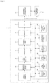
- FIG. 1 A configuration example of the sensor device 1 is illustrated in Fig. 1 .
- an external processor 11 and an external sensor 12 are also illustrated as external devices that perform data communication with the sensor device 1.
- the external processor 11 is assumed to be a general-purpose processor connected for communication with the sensor device 1.
- the sensor device 1 includes units configured as an image sensor device, a memory device such as a dynamic random access memory (DRAM), and an artificial intelligence (AI) function processor as hardware.
- a memory device such as a dynamic random access memory (DRAM)
- AI artificial intelligence
- the three units have a 3-layer stacked structure, have a so-called 1-layer flat configuration, or have a 2-layer stacked structure (for example, the memory device and the AI function processor are in the same layer).
- the sensor device 1 includes an array sensor 2, an amplitude control circuit 10, an analog-to-digital converter (ADC)/pixel selector 3, a buffer 4, a logical unit 5, a memory 6, an interface unit 7, and a calculation unit 8.
- ADC analog-to-digital converter
- the array sensor 2 is configured such that detection elements are light-receiving elements for visible light or invisible light and a plurality of pixels including the light-receiving elements are arrayed 1-dimensionally or 2-dimensionally. For example, many pixels are arrayed 2-dimensionally in the row and column directions and 2-dimensional image signals are output through photoelectric conversion in the light-receiving elements of the pixels.
- the array sensor 2 is assumed to be an image sensor that outputs a 2-dimensional image signal.
- the array sensor 2 in the sensor device 1 can also be configured as a sensor array module in which acoustic wave detection elements are arrayed, a sensor array module in which tactile information detection elements are arrayed, or the like.
- the amplitude control circuit 10 performs amplitude control of an electrical signal (an analog signal) photoelectrically converted by the array sensor 2.
- the amplitude control circuit 10 is configured to be able to change an amplitude ratio based on an instruction from the calculation unit 8, and this point will be described later.
- the electrical signal photoelectrically converted by the array sensor 2 is input to the ADC/pixel selector 3 via the amplitude control circuit 10.
- the ADC/pixel selector 3 converts the electrical signal which is the input analog signal into digital data and outputs an image signal as the digital data.
- the ADC/pixel selector 3 has a pixel selection function for pixels (image sensor) of the array sensor 2.
- a photoelectrically converted signal can be acquired for only a selected pixel in the array sensor 2, can be converted into digital data, and can be output. That is, the ADC/pixel selector 3 normally converts photoelectrically converted signals for all the effective pixels forming an image of one frame into digital data and outputs the digital data, but can also convert photoelectrically converted signals for only selected pixels into digital data and output the digital data.
- the ADC/pixel selector 3 acquires the image signal in units of frames.
- the image signal of each frame is temporarily stored in the buffer 4, is read at an appropriate timing, and is supplied for a process of the logical unit 5.
- the logical unit 5 performs various kinds of necessary signal processing (image processing) on each of the input frame image signals.
- the logical unit 5 is assumed to adjust image quality through processes such as color correction, gamma correction, color gradation processing, gain processing, and a contour enhancement process.
- the logical unit 5 is also assumed to perform a process of changing a data size, such as a data compression process, resolution conversion, or frame rate conversion.
- a parameter used for each process is set. For example, there are setting values such as a gain value, a compression ratio, a frame rate, and a correction coefficient of color or luminance.
- the logical unit 5 performs a necessary process using the parameter set for each process.
- the parameters are set by the calculation unit 8 in some cases.
- An image signal processed by the logical unit 5 is stored in the memory 6 configured as, for example, a DRAM.
- a DRAM a static random access memory (SRAM), a magnetoresistive random access memory (MRAM), or the like is assumed.
- the MRAM is a memory that stores data by magnetism and it is known that a tunneling magnetoresistive (TMR) element is used instead of a magnetic core.
- TMR tunneling magnetoresistive
- a very thin layer of an insulating material corresponding to several atoms is interposed by magnetic substances so that electrical resistance varies in accordance with a direction of magnetization of the layers of the magnetic substances.
- a direction of magnetization of the TMR element does not vary even when power is cut off, and thus a nonvolatile memory is realized.
- a larger write current is necessary with further micronization. Therefore, a spin torque transfer (STT)-MRAM in which, in order to realize micronization of a memory cell, STT is used to flow and write electrons of which spin is complete without using a magnetic field is known.
- STT spin torque transfer
- another storage element may be used as a specific example of the memory 6.
- An image signal stored in the memory 6 is transmitted and output at a necessary timing to the external processor 11 or the like by the interface unit 7.
- the external processor 11 performs image analysis and an image recognition process on an image signal transmitted from the sensor device 1 to perform necessary object detection or the like.
- the external processor 11 can also refer to detection information of the external sensor 12.
- the external processor 11 is connected to the sensor device 1 in a wired or wireless manner.
- An imaging device that includes the sensor device 1 has a network communication function and is also configured to be able to transmit an image signal obtained by the sensor device 1 (a captured image signal) to an external computer device (for example, a cloud server or the like) of the imaging device via a network such as the Internet or a local area network (LAN).
- the external processor 11 is considered to be, for example, a processor in a cloud computing system in some cases.
- the calculation unit 8 is configured as, for example, a single AI processor.
- the calculation unit 8 includes a key frame selection unit 81, an object region recognition unit 82, a class identification unit 83, a parameter selection unit 84, an encryption control unit 85, and an unauthorized access detection unit 86, as illustrated, as executable calculation functions. These calculation functions may be configured by a plurality of processors.
- the key frame selection unit 81 performs a process of selecting a key frame from frames of an image signal serving as a moving image in response to a predetermined algorithm or an instruction.
- the object region recognition unit 82 detects a region of an object which is a detection candidate in the frame of the image signal photoelectrically converted by the array sensor 2 and acquired by the ADC/pixel selector 3 or performs a recognition process of a region (a bounding box) surrounding a detection target object in an image (a frame) of this object.
- the object detected from the image signal is an object which is a detection target for the purpose of recognition from an image.
- a detection target object differs in accordance with a detection purpose, a processing capability, a kind of application, or the like of the sensor device 1 or the external processor 11. However, there is a possibility of all objects being detection target objects mentioned herein.
- the object region recognition unit 82 performs a process of calculating a region of interest (ROI) which is region information indicating a processing target region (a region of interest) based on the bounding box.
- ROI region of interest
- the class identification unit 83 sorts a class of an object detected by the object region recognition unit 82.
- the class is information indicating a category of an object. For example, objects to be detected are classified into “people,” “automobiles,” “airplanes,” “ships,” “trucks,” “birds,” “cats,” “dogs,” “deer,” “frogs,” “horses,” etc.
- the parameter selection unit 84 stores parameters for signal processing in accordance with each class and selects a corresponding single parameter or a plurality of corresponding parameters using a class of a detected object identified by the class identification unit 83, the bounding box, or the like.
- the single parameter or the plurality of parameters are set in the logical unit 5.
- processes of various functions by the foregoing calculation unit 8 are processes not normally performed in the image sensor.
- object detection, class recognition, and control based on the object detection and the class recognition are performed inside the image sensor.
- an image signal to be supplied to the external processor 11 can be set to be appropriate in accordance with a detection purpose, or an amount of data can be appropriately reduced so that the detection capability does not deteriorate.
- the encryption control unit 85 performs control such that the image signal obtained through imaging in the array sensor 2 is encrypted. A specific example of a process performed by the encryption control unit 85 to encrypt the image signal will be described again.
- the unauthorized access detection unit 86 detects unauthorized access from the outside of the sensor device 1. Specifically, the unauthorized access detection unit 86 in this example detects unauthorized access to data stored in the memory 6 from the outside. When the unauthorized access detection unit 86 detects unauthorized access, log information (for example, information or the like indicating a detection date and time or a kind of unauthorized access) is recorded in a predetermined region of the memory 6.
- log information for example, information or the like indicating a detection date and time or a kind of unauthorized access
- the sensor device 1 encrypts the image signal.
- pseudorandom numbers generated by software are used as random numbers used for encryption in many cases.
- a pseudorandom number is generated by an algorithm for calculating a numerical value, and a true random number cannot be generated. Therefore, there is a risk of deciphering and replicating an encryption key.
- the photoelectric random number is a random number obtained based on photoelectric conversion by the array sensor 2. Specifically, in this example, a value of an electrical signal of each pixel obtained through the photoelectric conversion of the array sensor 2 is acquired as a photoelectric random number to generate an encryption key.
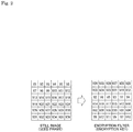
- Fig. 2 illustrates an example of a scheme of generating an encryption filter (an encryption key) based on a photoelectric random number.
- values of electrical signals of pixels obtained through the photoelectric conversion of the array sensor 2 are exemplified on the left side of the drawing.
- each pixel value (luminance value) of an image (a still image) obtained through imaging in the array sensor 2 is used as a photoelectric random number.
- a frame image captured to obtain a photoelectric random number in other words, a frame image which is an origin of the photoelectric random number, is referred to as a "seed frame" here.
- the values of the electrical signals of the pixels are not used as an encryption key, but an encryption key is generated in a format in which at least some of the values of the electrical signals of the pixels are assigned to pixel positions different from pixel positions at which the values of the electrical signals are obtained, as exemplified on the right side of the drawing.
- the encryption key is generated by shuffling the pixel positions with respect to the values of the electrical signals of the pixels obtained as the photoelectric random numbers.
- the values of the electric signals of the pixels can also be modulated and used by a predetermined algorithm.
- a value obtained by multiplying the value of the electric signal of each pixel by a predetermined coefficient is exemplified as a random number of that pixel.
- the value of the electrical signal of each pixel contains a value after a decimal point, it is possible to adopt a scheme of setting a value obtained as an integer of the value after the decimal point as a random number at that pixel position.
- an image signal read from the array sensor 2 is temporarily stored in a plain text state in the memory and the stored image signal is encrypted.
- an image signal is not stored in plain text in the memory because signals read from the pixels of the array sensor 2 are encrypted.
- the amplitude control circuit 10 illustrated in Fig. 1 performs amplitude control on the signal read from the pixels of the array sensor 2 with the coefficient in accordance with the encryption key illustrated in Fig. 2 , and thus the encryption of the read signal is realized.
- Fig. 3 is a diagram illustrating an image of encryption of a read signal by the amplitude control circuit 10.
- the signal read from each pixel in the array sensor 2 (in this case, a charge signal) is multiplied by the coefficient in accordance with the encryption key by an amplifier included in the amplitude control circuit 10.
- the amplitude of the read signal of each pixel is controlled in an analog signal stage in this way, and the read signal is subjected to A/D conversion by the ADC/pixel selector 3 and is stored in the memory 6 via the buffer 4 and the logical unit 5.
- the encryption control unit 85 encrypts the signal read from each pixel in the array sensor 2 by setting the coefficient in accordance with the encryption key in the amplifier.
- Fig. 3 is merely an image diagram and it is not essential to provide the amplifier at each pixel in the amplitude control circuit 10.
- the amplifier included in the amplitude control circuit 10 is one amplifier common to each pixel in some cases. In this case, the amplitude control of each pixel is performed in a time division manner.
- a read signal of an individual pixel can be said to be a signal that forms an image signal. That is, the read signal of the individual pixel belongs to the image signal in the sense that the read signal is a signal that forms a part of the image signal.
- the read signal is encrypted in accordance with an analog signal
- the read signal can also be encrypted in accordance with a digital signal after A/D conversion.
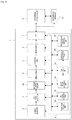
- Fig. 4 is a diagram illustrating a configuration example of the sensor device 1 when the read signal is encrypted using a digital signal.
- the sensor device 1 includes an amplitude control circuit 10A that performs amplitude control on a read signal converted into a digital signal by the ADC/pixel selector 3 instead of the amplitude control circuit 10.
- a process by the encryption control unit 85 is the same except that a coefficient setting target of each pixel in accordance with the encryption key is changed from the amplitude control circuit 10 to the amplitude control circuit 10A. Therefore, repeated description will be avoided.
- the analog read signal is encrypted, there is concern of reproduction of an image deteriorating with regard to an image obtained by decoding an encrypted image.
- the target can be detected or analyzed as reproducibility of the image and it is considered that a practical problem does not occur.
- the foregoing encryption performed on the read signal is a kind of encryption in accordance with a stream encryption scheme.
- the stream encryption scheme is an encryption method of encrypting plain text in a predetermined data unit such as a bit unit or a byte unit.
- a predetermined data unit such as a bit unit or a byte unit.
- the sensor device 1 achieves tamper resistance in terms of hardware.
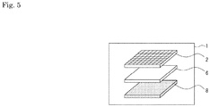
- chips of the array sensor 2, the memory 6, and the calculation unit 8 are packaged as one.
- a chip serving as the memory 6 is stacked on a chip serving as the calculation unit 8 and a chip serving as the array sensor 2 is further stacked on the chip serving as the memory 6.
- an encryption unit that encrypts a read signal is formed, for example, inside the chip serving as the array sensor 2.
- the encryption control unit 85 that generates an encryption key based on the photoelectric random number and causes the encryption unit to perform encryption based on the encryption key is included in the chip serving as the calculation unit 8.
- Fig. 6 is a diagram illustrating another example of the structure of the sensor device 1.
- a difference from Fig. 5 is reversion of a hierarchical relation between the calculation unit 8 and the memory 6.
- Fig. 7 is a diagram illustrating still another example of the sensor device 1.
- a difference from Fig. 5 is that a plurality of chips serving as the memory 6 are stacked (two layers in the illustrated example).
- the memory 6 can be formed in the same layer as the calculation unit 8 as a structure of two layers or the array sensor 2, the memory 6, and the calculation unit 8 can also be formed in the same layer as a structure of one layer.
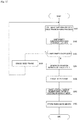
- the calculation unit 8 starts the process illustrated in Fig. 8 in response to activation and detection of an unauthorized access by the unauthorized access detection unit 86.
- the process illustrated in Fig. 8 By starting the process illustrated in Fig. 8 in response to the detection of the unauthorized access, acquisition of the photoelectric random number (S101) or generation of the encryption key (S105) is performed in response to the detection of the unauthorized access. That is, the photoelectric random number is re-acquired in response to the detection of the unauthorized access and the encryption key is re-generated based on the re-acquired photoelectric random number.
- the process illustrated in Fig. 8 can also be started based on another condition. For example, the process can be started in response to an instruction (for example, an instruction in accordance with an operation input) from the outside or every given interval.
- the calculation unit 8 performs a still image capturing process of in step S101.
- the still image capturing process is a process of capturing still images which are an origin of generation of the encryption key.
- the calculation unit 8 controls the array sensor 2 such that images corresponding to one frame are captured (charges of each pixel are read).
- images (still images) corresponding to one frame which are an origin of the generation of the encryption key are referred to as a "seed frame" here.
- image data is stored as the seed frame in the memory 6.
- step S102 subsequent to step S101 the calculation unit 8 performs a uniformity checking process for pixel values.
- the uniformity checking process is a process of checking uniformity of luminance values of the pixels in the seed frame. Specifically, the calculation unit 8 counts the number of pixels of which luminance values are zero or a satirized value (a maximum value).
- a uniformity checking process for the pixel values a uniformity checking process in which a value of a read signal is a target can also be performed.
- step S103 the calculation unit 8 determines whether the uniformity is excessive. Specifically, it is determined in step S102 whether the number of counted pixels is equal to or greater than a predetermined threshold (for example, a value corresponding to 30% to 50% of the number of effective pixels). When it is determined in step S102 the number of counted pixels is equal to or greater than the predetermined threshold and the uniformity is excessive, the process proceeds to step S104 and the calculation unit 8 performs a process of erasing the seed frame, that is, a process of erasing the image data which is the seed frame stored in the memory 6. Then, the process returns to step S101.
- a predetermined threshold for example, a value corresponding to 30% to 50% of the number of effective pixels.
- the seed frame can be imaged again to correspond to a case where randomness of the pixel values of the seed frame is low. That is, the photoelectric random number can be acquired again to correspond to a case where the randomness of the photoelectric random number is low. Accordingly, it is possible to prevent encryption with the encryption key based on the random number with low randomness and it is possible to achieve an improvement in security.
- step S103 when it is determined in step S103 that the number of counted pixels is not equal to or greater than the threshold and the uniformity is not excessive, the process proceeds to step S105 and the calculation unit 8 generates the encryption key. Specifically, in this example, based on a luminance value of each pixel in the seed frame, the encryption key indicating a coefficient to be set in each amplifier in the amplitude control circuit 10 (or 10A) is generated.
- the encryption key in the format in which the luminance values of the pixels are assigned to the pixel position at which the luminance values are obtained is not generated, but the encryption key in the format in which at least some of the luminance values of the pixels are assigned to pixel positions different from the pixel positions at which the luminance values are obtained is generated.
- the encryption key in the format in which at least some of the luminance values of the pixels are assigned to pixel positions different from the pixel positions at which the luminance values are obtained is generated.
- step S106 the calculation unit 8 performs a process of erasing the seed frame, that is, the process of erasing the image data which is the seed frame stored in the memory 6 through the imaging process of step S101.
- a process of erasing the seed frame By performing the process of erasing the seed frame, it is possible to prevent the photelectric random number from being estimated due to leaking of the image which is an origin of the photoelectric random number. For example, when the processing capability of the calculation unit 8 is high or the image size of the seed frame is small, it is not essential to temporarily store the seed frame in the memory 6.
- the calculation unit 8 receives the photoelectric random number from, for example, the amplitude control circuit 10 (or 10A) and generates the encryption key in step S105 via the processes of steps S102 and S103.
- the erasing process of step S106 is unnecessary (of course, the erasing process of step S104 is also unnecessary).
- step S107 there is an existing key, the calculation unit 8 erases the existing key.
- the encryption key is stored in the memory 6 through the previously performed process of step S108.
- the process of step S107 is the process of erasing the encryption key when the existing encryption key is stored in the memory 6 in this way.
- step S108 the calculation unit 8 performs a process of storing the encryption key. That is, the process of storing the encryption key generated in step S105 in the memory 6 is performed.
- the calculation unit 8 ends the series of processes illustrated in Fig. 8 .
- the image signal obtained through the imaging in the array sensor 2 is set to a target to perform encryption using the encryption key stored in step S108.
- the calculation unit 8 (the encryption control unit 85) ends the process illustrated in Fig. 8
- the coefficient of each pixel based on the stored encryption key is set in each amplifier in the amplitude control circuit 10 (or 10A) and the encryption based on the encryption key stored in the image signal obtained through the imaging in the array sensor 2 is performed.
- the array sensor 2 performs imaging a moving image, and each frame image that forms a moving image is encrypted by the amplitude control circuit 10 (or 10A).
- the image signal is encrypted based on the photoelectric random number obtained during the frame period different from that of an encryption target image signal.
- it is possible to increase difficulty in estimating the encryption key from the encrypted image, and thus it is possible to achieve an improvement in security. It is also possible to encrypt the image signal based on the photoelectric random number obtained during the same frame period as that of the encryption target image signal.
- the calculation unit 8 analyzes an attribute or an operation of a target object, specifically, an object of a target class among the above-described classes. For example, when images obtained through imaging in the array sensor 2 are monitored images in stores, attributes such as the number of target customers (people), sex, ages, heights, and weights of the customers, presence or absence of glasses, or prevention or non-prevention can be analyzed, or actions of customers such as changes in postures or movement trajectories (traffic lines) of the customers in the store can be analyzed by analyzing the images.
- attributes such as the number of target customers (people), sex, ages, heights, and weights of the customers, presence or absence of glasses, or prevention or non-prevention can be analyzed, or actions of customers such as changes in postures or movement trajectories (traffic lines) of the customers in the store can be analyzed by analyzing the images.
- images obtained through imaging in the array sensor 2 are monitored images of vehicles traveling on roads, attributes such as models or colors of target vehicles, the number of passengers, and sex of the passengers can be analyzed or actions such as traffic lines and vehicle speeds on roads can be analyzed.
- a configuration in which moving-image data subjected to encryption in the above-described embodiment (in the drawing, "encrypted moving-image data”) and data indicating a result of the analysis (in the drawing, "analyzed result data”) are output to the external processor 11 can be adopted in the sensor device 1.
- the interface unit 7 can output the analyzed result data as metadata of the encrypted moving-image data.
- the analyzed result data can be output independently from the encrypted moving-image data.
- the side of the external processor 11 gives an instruction of necessary information to the interface unit 7 and the interface unit 7 outputs information in accordance with the information.
- the encryption is performed at the time of the read signal. Therefore, for the calculation unit 8 to perform the object detection or analysis, it is necessary to decode the encrypted image signal.
- the calculation unit 8 performs the object detection or analysis process while decoding the encrypted image data stored in the memory 6 in the on-the-fly scheme.
- the on-the-fly scheme is a scheme of processing encrypted data while decoding the encrypted data in a byte unit or a word unit.
- the scheme is a scheme of delivering a common key using encryption of a public key.
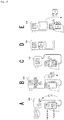
- the image receiver side generates a public key and a private key and delivers the public key to a camera device 100 including the sensor device 1 (see Fig. 10A ).
- the side of the camera device 100 acquiring the public key sets an encryption key generated based on the above-described photoelectric random number as a common key, encrypts the common key with the public key, and transmits the encrypted common key to the image receiver side (see Fig. 10B ). Then, the image receiver side decodes the transmitted common key (a decoded key) using the private key generated in Fig. 10A (see Fig. 10C ). Thus, thereafter, the image receiver side can decode the encrypted moving-image data received from the camera device 100 using the decoded common key at a high speed.
- Fig. 10D schematically illustrates a situation in which an image is encrypted using the common key on the side of the camera device 100.
- Fig. 10E schematically illustrates a situation in which the image data encrypted with the common key is decoded using the common key on the image receiver side.
- encryption of a target region in an image signal is performed. Specifically, in the second embodiment, encryption based on an encryption key different between an entire image and a target region is performed. By performing encryption based on an encryption key different between a region of a specific portion and the other region of the target region, a concealing level of information is changed step by step separately in accordance with a decoding key retained on the image receiver side.
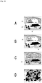
- Figs. 11 and 12 are diagrams illustrating images of stepwise encryption according to the second embodiment.
- Fig. 11 illustrates an image of stepwise encryption when a target class is a person.
- Fig. 11A illustrates an image before encryption.
- a target region AT is an entire region of a portion in which a person is shown in the image.
- a specific region AS which is a region of a specific part is a region of the face of the person.
- Fig. 11B illustrates an image in which only the specific region AS is encrypted
- Fig. 11C illustrates an image in which only the target region AT including the specific region AS is encrypted
- Fig. 11D illustrates an image in which the entire region of the image is encrypted.
- Fig. 12 is a diagram illustrating an image of stepwise encryption when a target class is a vehicle.
- Fig. 12A illustrates an image before encryption.
- a target region AT is an entire region of a portion in which a vehicle is shown in the image and specific regions AS are regions of passengers of the vehicle and a number plate.
- Fig. 12B illustrates an image in which only the specific region AS is encrypted
- Fig. 12C illustrates an image in which only the target region AT including the specific regions AS is encrypted
- Fig. 12D illustrates an image in which the entire region of the image is encrypted.
- the image before encryption illustrated in Fig. 12A is personal information in which individuals can be specified since both the passengers and the number plate are shown. Therefore, it is not appropriate to use the image for marketing data or the like.
- the images in which only the specific region AS illustrated in Fig. 12B is encrypted for example, the models or the number of vehicles can be determined for the purpose of marketing of vehicle markers without acquiring information such as the passengers including a driver or the number plate in which individuals can be specified.
- the image in which only the target region AT illustrated in Fig. 12C is encrypted only information regarding the number of vehicles and movements can be acquired without acquiring individual information or model information. For example, a congested situation can be determined.
- At least three kinds of encryption keys are generated as the encryption keys.
- Fig. 13 is a diagram illustrating an example of a specific scheme for stepwise encryption.
- the target image is encrypted based on a combined key in which the plurality of encryption keys are combined.
- the third encryption key for encrypting the specific region AT, the second encryption key for encrypting the entire region of the target region AT, and the first encryption key for encrypting the entire region of the image are each prepared.
- three kinds of encryption keys are generated, three kinds of photoelectric random numbers may be obtained (that is, three kinds of seed frames may be imaged).
- the three kinds of encryption keys are generated from a common photoelectric random number to shorten a time necessary to generate the encryption keys.
- three kinds of random numbers (referred to as first, second, and third random numbers) in which disposition of a numeral value of each pixel is different in the common photoelectric random number are generated.
- the third encryption key is generated as an encryption key in which a numerical value of each pixel of the specific region AS is extracted among numeral values of the third random number.
- the second encryption key is generated as an encryption key in which a numerical value of each pixel of the target region AT is extracted among numerical values of the second random number.
- the first encryption key is generated as an encryption key in which the first random is applied as it is.
- the encryption key in which the first, second, and third encryption keys are combined is generated as the combined key.
- the target image is encrypted based on the combined key.
- Fig. 14 is a diagram illustrating a change example of a concealing level.
- level 0 means that there is no key
- level 1 means that only the first encryption key is retained
- level 2 means that a combined key of the first and second encryption keys
- level 3 means that a combined key of the first, second, and third encryption keys is retained.
- an image of which the entire region is encrypted can be obtained without decoding an encrypted image.
- a region other than the target region AT can be decoded using the first encryption key. Accordingly, an image in which only the target region AT is encrypted is obtained.
- level 2 on the image receiver side, a region other than the specific region AS can be decoded using the combined key of the first and second encryption keys, and thus an image in which only the specific region AS in a target is encrypted is obtained.
- level 3 on the image receiver side, the entire region of the image can be decoded using the combined key of the first, second, and third encryption keys. In this case, an image with no concealed information can be obtained.
- the encryption target image is a moving image
- an object which is a target shown in the image is likely to be displaced in the image over time. Therefore, when the foregoing target region AT which is a target is encrypted, it is necessary to track the target.
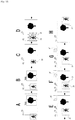
- Fig. 15 the class of a target is a "person.”
- a specific region AC and the other region are not distinguished in the target region AT, and only the target region AT in the image and the other region are encrypted and separated.
- a frame F1 illustrated in Fig. 15A indicates a state in which the person which is the target class is not framed in.
- an example is given in which an object which is a "tree" and is not a target class is identified in the image.
- the entire region of the image is encrypted irrespective of whether there is a target. That is, in this example, an image of each frame F is encrypted in the amplitude control circuit 10 (or 10A) based on the first encryption key corresponding to the entire region of the image, and subsequently is stored in the memory 6.
- a colored key mark indicates that the entire region of the image which is a target is encrypted as an output image.
- the calculation unit 8 performs region detection or class identification of a region of an object in the image (the processes of the above-described object region recognition unit 82 and class identification unit 83). To perform such processes, the calculation unit 8 decodes the frame image which has been encrypted and stored. That is, the calculation unit 8 performs a process of tracking a target while decoding the frame image encrypted based on the first encryption key. The calculation unit 8 performs the decoding at that time in accordance with the on-the-fly scheme. Thus, it is possible to reduce a possibility of an image signal in a plain text state leaking when the target is tracked, and thus it is possible to achieve an improvement in security.
- a frame F2 illustrated in Fig. 15B indicates a state in which the "person” who is the target class. In this state, the "person” who is the target class is identified along with the "tree" which has already been identified.
- the calculation unit 8 calculates a bounding box 20 at accurate position coordinates surrounding an area of the object. For example, an example of the bounding box 20 of an image of the person who is the target class is illustrated in Fig. 15C . That is, the bounding box 20 is calculated as a more accurate region of the object corresponding to the target class. Further, the calculation unit 8 (the object region recognition unit 82) calculates an ROI 21 which is a region of interest based on the bounding box 20.
- Fig. 15D illustrates the ROI 21 and the bounding box 20.
- the ROI 21 is calculated, for example, by expanding an aspect ratio (x ⁇ y) of the bounding box 20 (ax ⁇ by).
- An expansion scale a and b can be set separately horizontally or vertically.
- An expansion ratio may be fixed, but can also be considered to be designated from the outside (for example, the external processor 11 or the like) of the sensor device 1.
- the ROI 21 is encrypted as the target region AT using an encryption key different from that of the entire region of the image.
- the frame F2 is a frame in which the target class is newly identified in the image and can be restated as a target-class-found frame.
- the target-class-found frame cannot be encrypted based on the second encryption key with regard to the ROI 21.
- the target-class-found frame is already encrypted based on only the first encryption key and is stored in the memory 6.
- the image region of the ROI 21 is not concealed and is disclosed to a retainer of only the first encryption key.
- Fig. 15E illustrates a frame F3 which is a frame subsequent to the frame F2.
- the ROI 21 is encrypted as a target based on the second encryption key.
- the ROI 21 is the ROI 21 calculated at the time point of the frame F2 which is the target-class-found frame.
- the person who is the target class is moving, the person is moving to a movement direction side from the frame F2 in the frame F3.
- the ROI 21 is in a range greater than the bounding box 20
- the person who is the target class enters the ROI 21 in the frame F3. That is, the person who is the target class enters a target range of the encryption based on the second encryption key.
- the bounding box 20 and the ROI 21 are similarly calculated with regard to the target class.
- the target class is tracked (see Fig. 15F ).
- the ROI 21 calculated in the immediately previous frame F is encrypted as the target based on the second encryption key (see Fig. 15G ).
- Fig. 15H illustrates a frame Fn after the "person" who is the target class is framed out.
- the ROI 21 is not calculated. Therefore, an image of the frame Fn is encrypted based on only the first encryption key.
- the ROI 21 is not limited to the rectangular region.
- the ROI 21 may be calculated from the area of the object of the target class using semantic segmentation, that is, object area detection at a pixel level.
- Fig. 16 is a diagram illustrating a modification example of an ROI 21 based on semantic segmentation.
- a pixel region of an object for example, a person
- a nonrectangular ROI 21 is set.
- a truck with a protrusion, a person riding a bicycle, or the like is not partially contained or is too large to be contained in the rectangular ROI 21 in some cases.
- a concealing region related to a target can be appropriately set without being excessive or deficient.
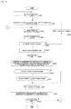
- Fig. 17 is a flowchart illustrating a countermeasure process from imaging of a seed frame to storing of a random number which is an origin of an encryption key.
- the same step numbers are given to processes similar to the processes described above in Fig. 8 , and description thereof will be omitted.
- the process illustrated in Fig. 17 is started in response to activation and detection of an unauthorized access by the unauthorized access detection unit 86.
- the process can also be started based on another condition. For example, the process can be started every given interval.
- At least some of the processes described in Figs. 17 and 18 can also be realized as processes by hardware.
- step S103 when the uniformity is determined in step S103 to be excessive, the process proceeds to step S201 and the calculation unit 8 generates a random number of each level.
- the specific region AS is not distinguished in the target region AT, two kinds of random numbers, the above-described first and second random numbers described as random numbers, are generated.
- the scheme of generating various kinds of random numbers based on the photoelectric random number of the seed frame has already been described. Therefore, repeated description thereof will be avoided.
- the calculation unit 8 performs the process of erasing the seed frame in step S106 in response to the random number generating process performed in step S201. Then, the calculation unit 8 performs a process of erasing an existing random number when there is the existing random number in step S202 in response to the erasing process performed in step S106. That is, the process is a process of erasing random numbers when there are the random numbers of the levels (the first and second random numbers) stored in the memory 6 in the previous performed process of step S203. In step S203 subsequent to step S202, the calculation unit 8 performs a process of storing the random number of each level generated in step S201 in the memory 6. Then, the series of processes illustrated in Fig. 17 ends.
- Fig. 18 is a flowchart illustrating a process of encrypting a target image based on a generated encryption key.
- the calculation unit 8 waits for a start of imaging of an encryption target image in step S301.
- the calculation unit 8 performs an encryption process with the first encryption key in step S302. That is, the coefficient of each pixel based on the first encryption key is instructed to the amplitude control circuit 10 (or 10A) to encrypt the read signal of the array sensor 2.
- the first encryption key is an encryption key in which the first random number is applied as it is.
- step S303 subsequent to step S302, the calculation unit 8 performs an object region recognition process. Further, subsequently, in step S304, the calculation unit 8 performs a class identification process.
- the object region recognition process of step S303 is a process of the above-described object region recognition unit 82. A process of detecting candidate objects from an image of a current frame and regions of the objects is performed.
- the class identification process of step S304 is a process of the above-described class identification unit 83.
- the class of the object detected in the object region recognition process is identified. When a plurality of objects or a plurality of kinds of objects are detected, the classes of the objects are identified and the objects are sorted into classes. For example, in the above case of Fig.
- the class identification and sorting are performed in such a manner that the number of objects of the class "tree” is one and the number of objects of the class "person” is one.
- the calculation unit 8 performs the processes of steps S303 and S304 while decoding the frame image encrypted in step S302 or step S313 to be described below in the on-the-fly scheme.
- step S305 subsequent to step S304 the calculation unit 8 determines whether there is a target class. That is, it is determined whether there is the target class among the classes identified in step S304.
- the calculation unit 8 waits for a next frame (waits for arrival of a next frame period) in step S306, and then the process returns to step S302. That is, until the target class is detected, the encryption process for the entire region of the image in step S302, the object region recognition process in step S303, and the class identification process in step S304 are repeatedly performed for each frame.
- step S305 When it is determined in step S305 that there is the target class, the process proceeds to step S307 and the calculation unit 8 calculates the bounding box 20. Subsequently, in step S308, the ROI 21 is calculated. Further, subsequently, in step S309, the calculation unit 8 generates a combined key obtained by combining the first encryption key and the second encryption key in which the numerical value of the second random number is applied to only the ROI 21.
- the calculation unit 8 determines in step S310 whether a current frame is the target-class-found frame.
- the calculation unit 8 performs a process of erasing the target-class-found frame in step S311.
- the target-class-found frame it is possible to prevent an image portion of a target from not being concealed irrespective of whether a key retention level is level 1.
- the calculation unit 8 passes the erasing process of step S311 and performs a process of waiting for a next frame in step S312.
- the calculation unit 8 performs the process of waiting for the next frame in step S312.
- the calculation unit 8 performs the encryption process with the combined key generated in the immediately previous frame in step S313. That is, the coefficient of each pixel based on the combined key is instructed to the amplitude control circuit 10 (or 10A) to encrypt the read signal of the array sensor 2.
- step S314 subsequent to step S313, the calculation unit 8 determines whether the imaging ends, that is, determines whether the imaging of the encryption target image enters an ending state, for example, by giving an instruction to end the imaging from the outside. When the imaging does not end, the calculation unit 8 returns the process to step S303. In this way, until the imaging ends, the above-described processes are repeated. That is, when there is continuously a target class, the calculation of the ROI with regard to the class target, the generation of the combined key based on the calculated ROI, and the encryption process based on the combined key generated in the previously previous frame are performed. When there is no target class, the encryption process is performed with the first encryption key without performing the encryption process with the combined key.
- the calculation unit 8 ends the series of processes illustrated in Fig. 18 .
- an expansion scale a and b in expansion (ax ⁇ by) of the aspect ratio (x ⁇ y) can also be considered to correspond to a frame rate. For example, when the frame rate is low, a time of a frame interval is lengthened and a movement amount of an object such as a person increases. Therefore, it is considered that the ROI 21 is greater than in a case where the frame rate is high.
- the bounding box 20 and the ROI 21 are calculated for the specific portion in a scheme similar to the above-described scheme and the third encryption key in which the numerical value of the third random number is applied to the calculated ROI 21 is generated. Moreover, a combined key obtained by combining the first, second, and third encryption keys may be generated and used to encrypt an image of a next frame.
- the sensor device 1 can be configured to output the analyzed result data along with the encrypted moving-image data to the outside (see Fig. 9 ).
- the target region AT is encrypted as the target.
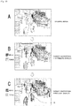
- the analyzed result data is not limited to data of text and can also be, for example, data displayed as an image, as exemplified in Fig. 19 .
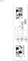
- Fig. 19A illustrates an original image before encryption.
- sex information of the target is displayed separately with a color added to a target region in an encrypted state.
- Fig. 19C illustrates an example in which posture information Ib obtained through the target analysis process is further superimposed on the target region in the encrypted state.
- an array sensor that includes color filters in, for example, a Bayer array or the like can be used as the array sensor 2. Even when a color image is obtained a captured image, the present technology can be appropriately applied.
- an encryption key to which random number values are assigned in units of color units can also be generated as an encryption key for image encryption.
- Fig. 20 is a diagram illustrating a generation example of an encryption key to which a random number is assigned in a color unit.
- a luminance value of one pixel in a color unit is assigned as a random number value of each pixel in the unit.
- a luminance value of the top left pixel is assigned as a random number value of each pixel in the unit.
- a value calculated through predetermined calculation using luminance values of pixels in the unit is assigned as a random number value of each pixel.
- an encryption target signal is set as an image signal in the encryption in which the photoelectric random number is used has been given above, but the encryption target signal is not limited to the image signal.
- the photoelectric random number is used for encryption with regard to the scheme of encrypting the signals read from the pixels of the array sensor 2 and the scheme of encrypting the target region as a target have been described above, but the random number used for encryption is not limited to the photoelectric random number with regard to these schemes.
- a pseudorandom number can also be used.
- a true random number a scheme in which a natural phenomenon of which prediction or reproduction is not substantially possible, such as a change in heat or sound, is detected by a corresponding sensor and random numbers are generated based on the values can be exemplified.
- the encryption device (the sensor device 1) according to an embodiment includes an encryption key generation unit (the encryption control unit 85) that generates an encryption key based on a photoelectric random number which is a random number obtained based on photoelectric conversion by an array sensor (the array sensor 2) in which a plurality of pixels including light-receiving elements for visible light or invisible light are arrayed 1-dimensionally or 2-dimensionally; and an encryption unit (the amplitude control circuit 10 or 10A) configured to encrypt a target signal based on the encryption key generated by the encryption key generation unit.
- an encryption key generation unit the encryption control unit 85
- the encryption control unit 85 that generates an encryption key based on a photoelectric random number which is a random number obtained based on photoelectric conversion by an array sensor (the array sensor 2) in which a plurality of pixels including light-receiving elements for visible light or invisible light are arrayed 1-dimensionally or 2-dimensionally
- an encryption unit (the amplitude control circuit 10 or 10A) configured to encrypt a target signal based on the
- the encryption key generation unit acquires a value of an electrical signal of each pixel obtained through the photoelectric conversion as the photoelectric random number and generates an encryption key.
- the encryption unit encrypts an image signal obtained through imaging in the array sensor based on the encryption key.
- the encryption key generation unit generates the encryption key in a format in which at least some of the values of the electrical signals of the pixels are assigned to pixel positions different from pixel positions at which the values of the electrical signals are obtained.
- the encryption key generation unit generates the encryption key based on the photoelectric random number obtained a frame period different from a frame period of an image signal which is an encryption target of the encryption unit.
- the encryption key generation unit re-acquirees the photoelectric random number when uniformity of values of the electrical signals in at least some of the pixels is acknowledged.
- the encryption key generation unit, the encryption unit, and the array sensor are configured in one package.
- the encryption key generation unit re-acquires the photoelectric random number in response to detection of an unauthorized access from outside of the encryption device.
- the encryption based on the re-acquired photoelectric random number can be performed. Accordingly, it is possible to achieve an improvement in security.
- the encryption key generation unit erases the previous generated encryption key from a memory in response to the re-acquisition of the photoelectric random number.
- the encryption key generation unit erases an image signal which is an origin of the photoelectric random number from a memory in response to generation of the encryption key.
- the encryption unit encrypts a target signal in accordance with a stream encryption scheme.
- An encryption method is an encryption method of generating an encryption key based on a photoelectric random number which is a random number obtained based on photoelectric conversion by an array sensor in which a plurality of pixels including light-receiving elements for visible light or invisible light are arrayed 1-dimensionally or 2-dimensionally; and encrypting a target signal based on the generated encryption key.
- the encryption method it is possible to obtain the same operational and advantageous effects as those of the encryption device according to the foregoing embodiment.
- a sensor device includes: an array sensor (the array sensor 2) in which a plurality of pixels including light-receiving elements for visible light or invisible light are arrayed 1-dimensionally or 2-dimensionally; and an encryption unit (the amplitude control circuit 10 or 10A and the encryption control unit 85) configured to encrypt a read signal from the pixels of the array sensor.
- the encryption unit includes a first amplitude control unit (the amplitude control circuit 10) that performs amplitude control of the read signal using an analog signal and the first amplitude control unit performs the amplitude control in accordance with an encryption key to encrypt the read signal.
- a first amplitude control unit the amplitude control circuit 10
- the encryption unit includes a second amplitude control unit (the amplitude control circuit 10A) that performs amplitude control of the read signal converted into a digital signal by an A/D converter and the second amplitude control unit performs the amplitude control in accordance with an encryption key to encrypt the read signal.
- a second amplitude control unit the amplitude control circuit 10A
- the encryption is performed through amplitude control on the digital signal, and it is possible to achieve a further improvement in accuracy of the encryption process than in a case where the amplitude control is performed on an analog signal. Accordingly, it is possible to improve reproducibility of image content when an encrypted image is decoded.
- the array sensor and the encryption unit are configured in one package.
- the encryption unit generates an encryption key based on a photoelectric random number which is a random number obtained based on photoelectric conversion by the array sensor and encrypts the read signal based on the generated encryption key.
- the encryption unit generates the encryption key based on the photoelectric random number obtained during a frame period different from a frame period of the read signal which is an encryption target.
- the encryption unit re-acquires the photoelectric random number in response to detection of an unauthorized access from outside of the sensor device.
- the encryption based on the re-acquired photoelectric random number can be performed. Accordingly, it is possible to achieve an improvement in security.
- the encryption unit erases the previous generated encryption key from a memory in response to the re-acquisition of the photoelectric random number.
- the encryption unit erases an image signal which is an origin of the photoelectric random number from a memory in response to generation of the encryption key.
- Another encryption method is an encryption method of encrypting a read signal from pixels of an array sensor, the plurality of pixels including light-receiving elements for visible light or invisible light and being arrayed 1-dimensionally or 2-dimensionally. According to the encryption method, it is possible to obtain the same operational and advantageous effects as those of the sensor device according to the foregoing embodiment.
- another encryption device (the sensor device 1) according to an embodiment includes an array sensor (the array sensor 2) in which a plurality of pixels including light-receiving elements for visible light or invisible light are arrayed 1-dimensionally or 2-dimensionally; a detection unit (the calculation unit 8: in particular, the object region recognition unit 82 and the class identification unit 83) that detects a region of a target shown in an image based on an image signal obtained through imaging in the array sensor; and an encryption unit (the amplitude control circuit 10 or 10A and the encryption control unit 85) that encrypts a target region in the image signal as a target based on information regarding the target region detected by the detection unit.
- an array sensor the array sensor 2 in which a plurality of pixels including light-receiving elements for visible light or invisible light are arrayed 1-dimensionally or 2-dimensionally
- a detection unit the calculation unit 8: in particular, the object region recognition unit 82 and the class identification unit 83
- an encryption unit (the amplitude control circuit 10 or 10A and the encryption control
- the encryption unit encrypts the entire image based on a first encryption key as encryption of an image signal and encrypts a target region based on the first encryption key and a second encryption key different from the first encryption key.
- a portion which can be decoded in an image is distinguished separately in accordance with a decoding key retained by the image receiver side. Specifically, when only a decoding key corresponding to the first encryption key is retained, only a region other than the target region in the image can be decoded. When decoding keys corresponding to the first and second encryption keys are retained, the entire image including the target region can be decoded. Accordingly, it is possible to realize a useful encryption method in which a concealing level of information can be changed step by step separately in accordance with the decoding keys retained on the image receiver side.
- the detection unit performs a process of recognizing a specific portion of a target and the encryption unit encrypts a region of the specific region and the other region in the target region based on different encryption keys.
- the sensor device includes an analysis unit (the calculation unit 8) that analyzes an attribute or an action of the target and an output unit (the interface unit 7) that outputs information indicating a result of the analysis by the analysis unit.
- an analysis unit the calculation unit 8 that analyzes an attribute or an action of the target
- an output unit the interface unit 7 that outputs information indicating a result of the analysis by the analysis unit.
- the detection unit decodes an image signal encrypted based on the first encryption key in accordance with an on-the-fly scheme and detects the target.
- the encryption unit encrypts the image signal based on a combined key obtained by combining a plurality of encryption keys.
- the encryption unit encrypts the target region as a target while tracking the target.
- an encryption target image is a moving image
- the encryption unit encrypts an image signal in accordance with a stream encryption scheme.
- preprocessing of the encryption of the image signal is not necessary. Accordingly, it is possible to speed up the encryption process.
- the array sensor and the encryption unit are configured in one package.
- the encryption unit generates an encryption key based on a photoelectric random number which is a random number obtained based on photoelectric conversion by the array sensor and encrypts the image signal based on the generated encryption key.
- the encryption unit encrypts a signal read from the pixel of the array sensor.
- a still another encryption method is an encryption method of detecting a region of a target shown in an image as a target region based on an image signal obtained through imaging in an array sensor in which a plurality of pixels including light-receiving elements for visible light or invisible light are arrayed 1-dimensionally or 2-dimensionally; and encrypting the target region in the image signal as a target based on information regarding the detected target region.
- the encryption method it is possible to obtain the same operational and advantageous effects as those of the sensor device according to the foregoing embodiment.
- the present technology can be configured as follows.
Landscapes
- Engineering & Computer Science (AREA)
- Signal Processing (AREA)
- Computer Networks & Wireless Communication (AREA)
- Theoretical Computer Science (AREA)
- Computer Security & Cryptography (AREA)
- Physics & Mathematics (AREA)
- General Physics & Mathematics (AREA)
- Health & Medical Sciences (AREA)
- Bioethics (AREA)
- General Health & Medical Sciences (AREA)
- Computer Hardware Design (AREA)
- Software Systems (AREA)
- General Engineering & Computer Science (AREA)
- Studio Devices (AREA)
- Image Input (AREA)
Applications Claiming Priority (2)
| Application Number | Priority Date | Filing Date | Title |
|---|---|---|---|
| JP2019013968 | 2019-01-30 | ||
| PCT/JP2020/002121 WO2020158540A1 (fr) | 2019-01-30 | 2020-01-22 | Dispositif de capteur et procédé de chiffrement |
Publications (3)
| Publication Number | Publication Date |
|---|---|
| EP3920165A1 true EP3920165A1 (fr) | 2021-12-08 |
| EP3920165A4 EP3920165A4 (fr) | 2022-02-23 |
| EP3920165B1 EP3920165B1 (fr) | 2024-09-11 |
Family
ID=71840941
Family Applications (1)
| Application Number | Title | Priority Date | Filing Date |
|---|---|---|---|
| EP20749773.6A Active EP3920165B1 (fr) | 2019-01-30 | 2020-01-22 | Dispositif de capteur et procédé de chiffrement |
Country Status (6)
| Country | Link |
|---|---|
| US (2) | US11955032B2 (fr) |
| EP (1) | EP3920165B1 (fr) |
| KR (1) | KR20210121025A (fr) |
| CN (1) | CN113330499B (fr) |
| TW (1) | TW202040989A (fr) |
| WO (1) | WO2020158540A1 (fr) |
Families Citing this family (8)
| Publication number | Priority date | Publication date | Assignee | Title |
|---|---|---|---|---|
| US11362825B2 (en) * | 2020-03-30 | 2022-06-14 | Citrix Systems, Inc. | Extended reality authentication |
| GB2607980A (en) * | 2020-03-30 | 2022-12-21 | Citrix Systems Inc | Extended reality authentication |
| US11558183B2 (en) * | 2020-05-15 | 2023-01-17 | Bank Of America Corporation | System for exchanging symmetric cryptographic keys using computer network port knocking |
| US11928187B1 (en) * | 2021-02-17 | 2024-03-12 | Bank Of America Corporation | Media hosting system employing a secured video stream |
| CN113031491B (zh) * | 2021-04-02 | 2025-05-23 | 贵州创新轻金属工艺装备工程技术研究中心有限公司 | 一种具有加密功能的4-20毫安模拟信号传感器和方法 |
| US20240202865A1 (en) * | 2022-12-19 | 2024-06-20 | Palantir Technologies Inc. | Image obfuscation |
| CN116634390B (zh) * | 2023-05-15 | 2023-11-10 | 南京晓庄学院 | 一种基于分布式无线传感器的数据传输管理系统 |
| CN118470647B (zh) * | 2024-07-09 | 2024-11-15 | 宁波永耀电力投资集团有限公司 | 一种基于数字孪生技术的电力监控方法及系统 |
Family Cites Families (26)
| Publication number | Priority date | Publication date | Assignee | Title |
|---|---|---|---|---|
| US5598472A (en) | 1994-12-22 | 1997-01-28 | Stanford Telecommunications, Inc. | Charge-coupled-device based all-analog wave form scrambling with applications in audio, video, video-on-demand, and TV systems |
| JP3610642B2 (ja) | 1995-09-25 | 2005-01-19 | 富士通株式会社 | 書画の暗号化及び復号化装置 |
| JPH118842A (ja) | 1997-06-18 | 1999-01-12 | Nippon Telegr & Teleph Corp <Ntt> | 画像スクランブル装置および画像スクランブル解除装置 |
| JP4320543B2 (ja) * | 2002-12-16 | 2009-08-26 | ソニー株式会社 | 映像信号処理システム、映像信号処理装置および方法、記録媒体、並びにプログラム |
| US7240208B1 (en) * | 2003-04-23 | 2007-07-03 | The United States Of America As Represented By The Administrator Of The National Aeronautics And Space Administration | Encrypting digital camera with automatic encryption key deletion |
| WO2006101645A1 (fr) | 2005-03-21 | 2006-09-28 | Dow Corning Corporation | Generation de nombres aleatoires a l'aide d'un guide d'ondes de diffusion |
| JP2007026051A (ja) * | 2005-07-15 | 2007-02-01 | Matsushita Electric Ind Co Ltd | 情報処理装置および情報処理システム |
| KR20070018360A (ko) | 2005-08-09 | 2007-02-14 | 삼성전자주식회사 | 디지털 카메라의 영상을 암호화하는 cmos 이미지 센서. |
| US20100226495A1 (en) | 2007-10-29 | 2010-09-09 | Michael Kelly | Digital readout method and apparatus |
| JP4348381B2 (ja) * | 2007-05-30 | 2009-10-21 | 富士通株式会社 | 画像暗号化/復号化装置、方法およびプログラム |
| KR101074951B1 (ko) * | 2007-05-30 | 2011-10-18 | 후지쯔 가부시끼가이샤 | 화상 암호화 장치, 화상 복호 장치, 방법, 및 기록 매체 |
| WO2008146391A1 (fr) * | 2007-05-31 | 2008-12-04 | Pfu Limited | Système de cryptage de données électroniques, système de cryptage, programme et procédé associé |
| JP4416017B2 (ja) | 2007-07-18 | 2010-02-17 | ソニー株式会社 | 撮像システム |
| JP2010226506A (ja) | 2009-03-24 | 2010-10-07 | Chugoku Electric Power Co Inc:The | デジタルカメラ、記憶装置、デジタルカメラの制御方法およびプログラム |
| CN102063694B (zh) * | 2010-11-17 | 2013-04-24 | 安徽工业大学 | 一种基于折纸变换的数字图像加密方法 |
| KR101758090B1 (ko) * | 2010-12-06 | 2017-07-17 | 삼성전자주식회사 | 이미지 센서 및 이미지 센서를 포함하는 카메라 시스템 |
| CN102572314B (zh) * | 2011-12-22 | 2015-01-14 | 格科微电子(上海)有限公司 | 图像传感器以及支付认证方法 |
| CN103248854B (zh) * | 2013-04-27 | 2016-04-20 | 东北大学 | 基于均匀置乱和混沌映射的医学图像加密方法 |
| CN103458316B (zh) * | 2013-07-22 | 2016-05-04 | 太原理工大学 | 一种图像加密方法 |
| US20150104002A1 (en) * | 2013-10-10 | 2015-04-16 | Elwha Llc | Methods, systems, and devices for handling image data from captured images |
| US9830467B1 (en) * | 2014-04-14 | 2017-11-28 | Michael Harold | System, method and apparatus for securely storing data on public networks |
| US9871658B2 (en) | 2015-03-24 | 2018-01-16 | Semiconductor Components Industries, Llc | Imaging systems with data encryption and embedding capabalities |
| CN107852471B (zh) | 2015-04-16 | 2020-09-18 | 普里露尼库斯股份有限公司 | 固体摄像装置、固体摄像装置的驱动方法以及电子设备 |
| CN106156654B (zh) * | 2016-08-30 | 2019-06-11 | 成都百润百成科技股份有限公司 | 文档加密装置与方法 |
| GB2560716B (en) * | 2017-03-20 | 2022-05-25 | Blueskytec Ltd | Electronic anti-tamper device |
| CN106972934A (zh) | 2017-04-28 | 2017-07-21 | 山东大学 | 一种基于puf的照相机图像存储系统 |
-
2020
- 2020-01-22 EP EP20749773.6A patent/EP3920165B1/fr active Active
- 2020-01-22 WO PCT/JP2020/002121 patent/WO2020158540A1/fr not_active Ceased
- 2020-01-22 KR KR1020217023363A patent/KR20210121025A/ko active Pending
- 2020-01-22 CN CN202080010527.6A patent/CN113330499B/zh active Active
- 2020-01-22 US US17/312,242 patent/US11955032B2/en active Active
- 2020-01-30 TW TW109102931A patent/TW202040989A/zh unknown
-
2023
- 2023-12-01 US US18/526,662 patent/US12603019B2/en active Active
Also Published As
| Publication number | Publication date |
|---|---|
| US20240119867A1 (en) | 2024-04-11 |
| WO2020158540A1 (fr) | 2020-08-06 |
| US11955032B2 (en) | 2024-04-09 |
| TW202040989A (zh) | 2020-11-01 |
| US20220028302A1 (en) | 2022-01-27 |
| CN113330499A (zh) | 2021-08-31 |
| EP3920165A4 (fr) | 2022-02-23 |
| CN113330499B (zh) | 2024-05-24 |
| EP3920165B1 (fr) | 2024-09-11 |
| US12603019B2 (en) | 2026-04-14 |
| KR20210121025A (ko) | 2021-10-07 |
Similar Documents
| Publication | Publication Date | Title |
|---|---|---|
| US12603019B2 (en) | Sensor device and encryption method | |
| US12549334B2 (en) | Sensor device and encryption method | |
| CN111160379B (zh) | 图像检测模型的训练方法及装置、目标检测方法及装置 | |
| CN111950424B (zh) | 一种视频数据处理方法、装置、计算机及可读存储介质 | |
| US8488061B2 (en) | Deriving video signatures that are insensitive to picture modification and frame-rate conversion | |
| US12177342B2 (en) | Cipher key generation apparatus and cipher key generation method | |
| US12087033B2 (en) | Information processing system, information processing method, image-capturing apparatus, and information processing apparatus | |
| EP3920463B1 (fr) | Dispositif de chiffrement et procédé de chiffrement | |
| US20240161443A1 (en) | Information processing system and learning model generation method | |
| EP3933776B1 (fr) | Procédé et dispositif de traitement d'images pour anonymiser une image en couleur numérique | |
| US12346481B2 (en) | Systems and methods for image encryption | |
| US11232314B2 (en) | Computer vision based approach to image injection detection | |
| Dubey et al. | An Enhanced Video Forgery Detection Using BiLSTM With HOG and LBP Features | |
| CN119625483A (zh) | 配电房智能巡检方法及系统 |
Legal Events
| Date | Code | Title | Description |
|---|---|---|---|
| STAA | Information on the status of an ep patent application or granted ep patent |
Free format text: STATUS: THE INTERNATIONAL PUBLICATION HAS BEEN MADE |
|
| PUAI | Public reference made under article 153(3) epc to a published international application that has entered the european phase |
Free format text: ORIGINAL CODE: 0009012 |
|
| STAA | Information on the status of an ep patent application or granted ep patent |
Free format text: STATUS: REQUEST FOR EXAMINATION WAS MADE |
|
| 17P | Request for examination filed |
Effective date: 20210616 |
|
| AK | Designated contracting states |
Kind code of ref document: A1 Designated state(s): AL AT BE BG CH CY CZ DE DK EE ES FI FR GB GR HR HU IE IS IT LI LT LU LV MC MK MT NL NO PL PT RO RS SE SI SK SM TR |
|
| A4 | Supplementary search report drawn up and despatched |
Effective date: 20220125 |
|
| RIC1 | Information provided on ipc code assigned before grant |
Ipc: H04K 1/00 20060101ALI20220119BHEP Ipc: G09C 1/00 20060101ALI20220119BHEP Ipc: G06F 21/62 20130101AFI20220119BHEP |
|
| DAV | Request for validation of the european patent (deleted) | ||
| DAX | Request for extension of the european patent (deleted) | ||
| REG | Reference to a national code |
Ref country code: DE Ref legal event code: R079 Free format text: PREVIOUS MAIN CLASS: G09C0001000000 Ipc: G06F0021620000 Ref country code: DE Ref legal event code: R079 Ref document number: 602020037574 Country of ref document: DE Free format text: PREVIOUS MAIN CLASS: G09C0001000000 Ipc: G06F0021620000 |
|
| GRAP | Despatch of communication of intention to grant a patent |
Free format text: ORIGINAL CODE: EPIDOSNIGR1 |
|
| STAA | Information on the status of an ep patent application or granted ep patent |
Free format text: STATUS: GRANT OF PATENT IS INTENDED |
|
| RIC1 | Information provided on ipc code assigned before grant |
Ipc: H04L 9/08 20060101ALI20240312BHEP Ipc: H04K 1/00 20060101ALI20240312BHEP Ipc: G06F 21/62 20130101AFI20240312BHEP |
|
| INTG | Intention to grant announced |
Effective date: 20240404 |
|
| GRAS | Grant fee paid |
Free format text: ORIGINAL CODE: EPIDOSNIGR3 |
|
| P01 | Opt-out of the competence of the unified patent court (upc) registered |
Free format text: CASE NUMBER: APP_39569/2024 Effective date: 20240703 |
|
| GRAA | (expected) grant |
Free format text: ORIGINAL CODE: 0009210 |
|
| STAA | Information on the status of an ep patent application or granted ep patent |
Free format text: STATUS: THE PATENT HAS BEEN GRANTED |
|
| AK | Designated contracting states |
Kind code of ref document: B1 Designated state(s): AL AT BE BG CH CY CZ DE DK EE ES FI FR GB GR HR HU IE IS IT LI LT LU LV MC MK MT NL NO PL PT RO RS SE SI SK SM TR |
|
| REG | Reference to a national code |
Ref country code: GB Ref legal event code: FG4D |
|
| REG | Reference to a national code |
Ref country code: CH Ref legal event code: EP |
|
| REG | Reference to a national code |
Ref country code: DE Ref legal event code: R096 Ref document number: 602020037574 Country of ref document: DE |
|
| REG | Reference to a national code |
Ref country code: IE Ref legal event code: FG4D |
|
| REG | Reference to a national code |
Ref country code: LT Ref legal event code: MG9D |
|
| PG25 | Lapsed in a contracting state [announced via postgrant information from national office to epo] |
Ref country code: NO Free format text: LAPSE BECAUSE OF FAILURE TO SUBMIT A TRANSLATION OF THE DESCRIPTION OR TO PAY THE FEE WITHIN THE PRESCRIBED TIME-LIMIT Effective date: 20241211 |
|
| REG | Reference to a national code |
Ref country code: NL Ref legal event code: MP Effective date: 20240911 |
|
| PG25 | Lapsed in a contracting state [announced via postgrant information from national office to epo] |
Ref country code: GR Free format text: LAPSE BECAUSE OF FAILURE TO SUBMIT A TRANSLATION OF THE DESCRIPTION OR TO PAY THE FEE WITHIN THE PRESCRIBED TIME-LIMIT Effective date: 20241212 Ref country code: FI Free format text: LAPSE BECAUSE OF FAILURE TO SUBMIT A TRANSLATION OF THE DESCRIPTION OR TO PAY THE FEE WITHIN THE PRESCRIBED TIME-LIMIT Effective date: 20240911 |
|
| PG25 | Lapsed in a contracting state [announced via postgrant information from national office to epo] |
Ref country code: BG Free format text: LAPSE BECAUSE OF FAILURE TO SUBMIT A TRANSLATION OF THE DESCRIPTION OR TO PAY THE FEE WITHIN THE PRESCRIBED TIME-LIMIT Effective date: 20240911 |
|
| PG25 | Lapsed in a contracting state [announced via postgrant information from national office to epo] |
Ref country code: LV Free format text: LAPSE BECAUSE OF FAILURE TO SUBMIT A TRANSLATION OF THE DESCRIPTION OR TO PAY THE FEE WITHIN THE PRESCRIBED TIME-LIMIT Effective date: 20240911 |
|
| PG25 | Lapsed in a contracting state [announced via postgrant information from national office to epo] |
Ref country code: HR Free format text: LAPSE BECAUSE OF FAILURE TO SUBMIT A TRANSLATION OF THE DESCRIPTION OR TO PAY THE FEE WITHIN THE PRESCRIBED TIME-LIMIT Effective date: 20240911 |
|
| PG25 | Lapsed in a contracting state [announced via postgrant information from national office to epo] |
Ref country code: ES Free format text: LAPSE BECAUSE OF FAILURE TO SUBMIT A TRANSLATION OF THE DESCRIPTION OR TO PAY THE FEE WITHIN THE PRESCRIBED TIME-LIMIT Effective date: 20240911 Ref country code: RS Free format text: LAPSE BECAUSE OF FAILURE TO SUBMIT A TRANSLATION OF THE DESCRIPTION OR TO PAY THE FEE WITHIN THE PRESCRIBED TIME-LIMIT Effective date: 20241211 |
|
| PG25 | Lapsed in a contracting state [announced via postgrant information from national office to epo] |
Ref country code: RS Free format text: LAPSE BECAUSE OF FAILURE TO SUBMIT A TRANSLATION OF THE DESCRIPTION OR TO PAY THE FEE WITHIN THE PRESCRIBED TIME-LIMIT Effective date: 20241211 Ref country code: NO Free format text: LAPSE BECAUSE OF FAILURE TO SUBMIT A TRANSLATION OF THE DESCRIPTION OR TO PAY THE FEE WITHIN THE PRESCRIBED TIME-LIMIT Effective date: 20241211 Ref country code: LV Free format text: LAPSE BECAUSE OF FAILURE TO SUBMIT A TRANSLATION OF THE DESCRIPTION OR TO PAY THE FEE WITHIN THE PRESCRIBED TIME-LIMIT Effective date: 20240911 Ref country code: HR Free format text: LAPSE BECAUSE OF FAILURE TO SUBMIT A TRANSLATION OF THE DESCRIPTION OR TO PAY THE FEE WITHIN THE PRESCRIBED TIME-LIMIT Effective date: 20240911 Ref country code: GR Free format text: LAPSE BECAUSE OF FAILURE TO SUBMIT A TRANSLATION OF THE DESCRIPTION OR TO PAY THE FEE WITHIN THE PRESCRIBED TIME-LIMIT Effective date: 20241212 Ref country code: FI Free format text: LAPSE BECAUSE OF FAILURE TO SUBMIT A TRANSLATION OF THE DESCRIPTION OR TO PAY THE FEE WITHIN THE PRESCRIBED TIME-LIMIT Effective date: 20240911 Ref country code: ES Free format text: LAPSE BECAUSE OF FAILURE TO SUBMIT A TRANSLATION OF THE DESCRIPTION OR TO PAY THE FEE WITHIN THE PRESCRIBED TIME-LIMIT Effective date: 20240911 Ref country code: BG Free format text: LAPSE BECAUSE OF FAILURE TO SUBMIT A TRANSLATION OF THE DESCRIPTION OR TO PAY THE FEE WITHIN THE PRESCRIBED TIME-LIMIT Effective date: 20240911 |
|
| REG | Reference to a national code |
Ref country code: AT Ref legal event code: MK05 Ref document number: 1723331 Country of ref document: AT Kind code of ref document: T Effective date: 20240911 |
|
| PG25 | Lapsed in a contracting state [announced via postgrant information from national office to epo] |
Ref country code: NL Free format text: LAPSE BECAUSE OF FAILURE TO SUBMIT A TRANSLATION OF THE DESCRIPTION OR TO PAY THE FEE WITHIN THE PRESCRIBED TIME-LIMIT Effective date: 20240911 |
|
| PG25 | Lapsed in a contracting state [announced via postgrant information from national office to epo] |
Ref country code: IS Free format text: LAPSE BECAUSE OF FAILURE TO SUBMIT A TRANSLATION OF THE DESCRIPTION OR TO PAY THE FEE WITHIN THE PRESCRIBED TIME-LIMIT Effective date: 20250111 Ref country code: PT Free format text: LAPSE BECAUSE OF FAILURE TO SUBMIT A TRANSLATION OF THE DESCRIPTION OR TO PAY THE FEE WITHIN THE PRESCRIBED TIME-LIMIT Effective date: 20250113 |
|
| PG25 | Lapsed in a contracting state [announced via postgrant information from national office to epo] |
Ref country code: SM Free format text: LAPSE BECAUSE OF FAILURE TO SUBMIT A TRANSLATION OF THE DESCRIPTION OR TO PAY THE FEE WITHIN THE PRESCRIBED TIME-LIMIT Effective date: 20240911 Ref country code: RO Free format text: LAPSE BECAUSE OF FAILURE TO SUBMIT A TRANSLATION OF THE DESCRIPTION OR TO PAY THE FEE WITHIN THE PRESCRIBED TIME-LIMIT Effective date: 20240911 |
|
| PG25 | Lapsed in a contracting state [announced via postgrant information from national office to epo] |
Ref country code: EE Free format text: LAPSE BECAUSE OF FAILURE TO SUBMIT A TRANSLATION OF THE DESCRIPTION OR TO PAY THE FEE WITHIN THE PRESCRIBED TIME-LIMIT Effective date: 20240911 Ref country code: AT Free format text: LAPSE BECAUSE OF FAILURE TO SUBMIT A TRANSLATION OF THE DESCRIPTION OR TO PAY THE FEE WITHIN THE PRESCRIBED TIME-LIMIT Effective date: 20240911 |
|
| PG25 | Lapsed in a contracting state [announced via postgrant information from national office to epo] |
Ref country code: CZ Free format text: LAPSE BECAUSE OF FAILURE TO SUBMIT A TRANSLATION OF THE DESCRIPTION OR TO PAY THE FEE WITHIN THE PRESCRIBED TIME-LIMIT Effective date: 20240911 Ref country code: PL Free format text: LAPSE BECAUSE OF FAILURE TO SUBMIT A TRANSLATION OF THE DESCRIPTION OR TO PAY THE FEE WITHIN THE PRESCRIBED TIME-LIMIT Effective date: 20240911 |
|
| PG25 | Lapsed in a contracting state [announced via postgrant information from national office to epo] |
Ref country code: SK Free format text: LAPSE BECAUSE OF FAILURE TO SUBMIT A TRANSLATION OF THE DESCRIPTION OR TO PAY THE FEE WITHIN THE PRESCRIBED TIME-LIMIT Effective date: 20240911 Ref country code: IT Free format text: LAPSE BECAUSE OF FAILURE TO SUBMIT A TRANSLATION OF THE DESCRIPTION OR TO PAY THE FEE WITHIN THE PRESCRIBED TIME-LIMIT Effective date: 20240911 |
|
| REG | Reference to a national code |
Ref country code: DE Ref legal event code: R097 Ref document number: 602020037574 Country of ref document: DE |
|
| PG25 | Lapsed in a contracting state [announced via postgrant information from national office to epo] |
Ref country code: DK Free format text: LAPSE BECAUSE OF FAILURE TO SUBMIT A TRANSLATION OF THE DESCRIPTION OR TO PAY THE FEE WITHIN THE PRESCRIBED TIME-LIMIT Effective date: 20240911 |
|
| PLBE | No opposition filed within time limit |
Free format text: ORIGINAL CODE: 0009261 |
|
| STAA | Information on the status of an ep patent application or granted ep patent |
Free format text: STATUS: NO OPPOSITION FILED WITHIN TIME LIMIT |
|
| 26N | No opposition filed |
Effective date: 20250612 |
|
| REG | Reference to a national code |
Ref country code: CH Ref legal event code: PL |
|
| PG25 | Lapsed in a contracting state [announced via postgrant information from national office to epo] |
Ref country code: SE Free format text: LAPSE BECAUSE OF FAILURE TO SUBMIT A TRANSLATION OF THE DESCRIPTION OR TO PAY THE FEE WITHIN THE PRESCRIBED TIME-LIMIT Effective date: 20240911 |
|
| PG25 | Lapsed in a contracting state [announced via postgrant information from national office to epo] |
Ref country code: MC Free format text: LAPSE BECAUSE OF FAILURE TO SUBMIT A TRANSLATION OF THE DESCRIPTION OR TO PAY THE FEE WITHIN THE PRESCRIBED TIME-LIMIT Effective date: 20240911 Ref country code: LU Free format text: LAPSE BECAUSE OF NON-PAYMENT OF DUE FEES Effective date: 20250122 |
|
| GBPC | Gb: european patent ceased through non-payment of renewal fee |
Effective date: 20250122 |
|
| PG25 | Lapsed in a contracting state [announced via postgrant information from national office to epo] |
Ref country code: GB Free format text: LAPSE BECAUSE OF NON-PAYMENT OF DUE FEES Effective date: 20250122 Ref country code: BE Free format text: LAPSE BECAUSE OF NON-PAYMENT OF DUE FEES Effective date: 20250131 |
|
| PG25 | Lapsed in a contracting state [announced via postgrant information from national office to epo] |
Ref country code: FR Free format text: LAPSE BECAUSE OF NON-PAYMENT OF DUE FEES Effective date: 20250131 |
|
| PG25 | Lapsed in a contracting state [announced via postgrant information from national office to epo] |
Ref country code: CH Free format text: LAPSE BECAUSE OF NON-PAYMENT OF DUE FEES Effective date: 20250131 |
|
| REG | Reference to a national code |
Ref country code: BE Ref legal event code: MM Effective date: 20250131 |
|
| PG25 | Lapsed in a contracting state [announced via postgrant information from national office to epo] |
Ref country code: IE Free format text: LAPSE BECAUSE OF NON-PAYMENT OF DUE FEES Effective date: 20250122 |
|
| PGFP | Annual fee paid to national office [announced via postgrant information from national office to epo] |
Ref country code: DE Payment date: 20251217 Year of fee payment: 7 |