EP3920632B1 - Procédé d'envoi d'informations, procédé de détection d'informations, dispositif de terminal et dispositif de réseau - Google Patents
Procédé d'envoi d'informations, procédé de détection d'informations, dispositif de terminal et dispositif de réseau Download PDFInfo
- Publication number
- EP3920632B1 EP3920632B1 EP20748554.1A EP20748554A EP3920632B1 EP 3920632 B1 EP3920632 B1 EP 3920632B1 EP 20748554 A EP20748554 A EP 20748554A EP 3920632 B1 EP3920632 B1 EP 3920632B1
- Authority
- EP
- European Patent Office
- Prior art keywords
- random access
- dci
- terminal device
- access type
- network device
- Prior art date
- Legal status (The legal status is an assumption and is not a legal conclusion. Google has not performed a legal analysis and makes no representation as to the accuracy of the status listed.)
- Active
Links
Images


Classifications
-
- H—ELECTRICITY
- H04—ELECTRIC COMMUNICATION TECHNIQUE
- H04W—WIRELESS COMMUNICATION NETWORKS
- H04W74/00—Wireless channel access
- H04W74/08—Non-scheduled access, e.g. ALOHA
- H04W74/0833—Random access procedures, e.g. with 4-step access
- H04W74/0841—Random access procedures, e.g. with 4-step access with collision treatment
- H04W74/0858—Random access procedures, e.g. with 4-step access with collision treatment collision detection
-
- H—ELECTRICITY
- H04—ELECTRIC COMMUNICATION TECHNIQUE
- H04W—WIRELESS COMMUNICATION NETWORKS
- H04W72/00—Local resource management
- H04W72/20—Control channels or signalling for resource management
- H04W72/23—Control channels or signalling for resource management in the downlink direction of a wireless link, i.e. towards a terminal
-
- H—ELECTRICITY
- H04—ELECTRIC COMMUNICATION TECHNIQUE
- H04W—WIRELESS COMMUNICATION NETWORKS
- H04W72/00—Local resource management
- H04W72/20—Control channels or signalling for resource management
- H04W72/23—Control channels or signalling for resource management in the downlink direction of a wireless link, i.e. towards a terminal
- H04W72/232—Control channels or signalling for resource management in the downlink direction of a wireless link, i.e. towards a terminal the control data signalling from the physical layer, e.g. DCI signalling
-
- H—ELECTRICITY
- H04—ELECTRIC COMMUNICATION TECHNIQUE
- H04W—WIRELESS COMMUNICATION NETWORKS
- H04W72/00—Local resource management
- H04W72/04—Wireless resource allocation
- H04W72/044—Wireless resource allocation based on the type of the allocated resource
- H04W72/0446—Resources in time domain, e.g. slots or frames
-
- H—ELECTRICITY
- H04—ELECTRIC COMMUNICATION TECHNIQUE
- H04W—WIRELESS COMMUNICATION NETWORKS
- H04W72/00—Local resource management
- H04W72/04—Wireless resource allocation
- H04W72/044—Wireless resource allocation based on the type of the allocated resource
- H04W72/0453—Resources in frequency domain, e.g. a carrier in FDMA
-
- H—ELECTRICITY
- H04—ELECTRIC COMMUNICATION TECHNIQUE
- H04W—WIRELESS COMMUNICATION NETWORKS
- H04W72/00—Local resource management
- H04W72/20—Control channels or signalling for resource management
-
- H—ELECTRICITY
- H04—ELECTRIC COMMUNICATION TECHNIQUE
- H04W—WIRELESS COMMUNICATION NETWORKS
- H04W74/00—Wireless channel access
- H04W74/002—Transmission of channel access control information
- H04W74/006—Transmission of channel access control information in the downlink, i.e. towards the terminal
-
- H—ELECTRICITY
- H04—ELECTRIC COMMUNICATION TECHNIQUE
- H04W—WIRELESS COMMUNICATION NETWORKS
- H04W74/00—Wireless channel access
- H04W74/08—Non-scheduled access, e.g. ALOHA
-
- H—ELECTRICITY
- H04—ELECTRIC COMMUNICATION TECHNIQUE
- H04W—WIRELESS COMMUNICATION NETWORKS
- H04W74/00—Wireless channel access
- H04W74/08—Non-scheduled access, e.g. ALOHA
- H04W74/0833—Random access procedures, e.g. with 4-step access
-
- H—ELECTRICITY
- H04—ELECTRIC COMMUNICATION TECHNIQUE
- H04W—WIRELESS COMMUNICATION NETWORKS
- H04W74/00—Wireless channel access
- H04W74/08—Non-scheduled access, e.g. ALOHA
- H04W74/0833—Random access procedures, e.g. with 4-step access
- H04W74/0836—Random access procedures, e.g. with 4-step access with 2-step access
Definitions
- This disclosure relates to the field of communications technologies, and in particular, to an information transmission method, an information detection method, a terminal device, a network device, and a computer-readable storage medium.
- an R15 terminal device User Equipment, UE
- an R16 UE possibly coexist in a cell.
- a random access response message transmitted by a network device to UE may be a Msg2 message (corresponding to the 4-step random access procedure), or a MsgB message (corresponding to the 2-step random access procedure).
- Msg2 message corresponding to the 4-step random access procedure
- MsgB message corresponding to the 2-step random access procedure
- WO2017/052199A1 provides a method for receiving DCI, which includes: receiving a common search space configuration for a common search space; receiving a first PDCCH scheduling a random access response; and receiving a second PDCCH carrying the DCI for the UE.
- the UE can monitor first PDCCH candidates of the common search space according to the common search space configuration in order to receive the first PDCCH.
- the UE can monitor second PDCCH candidates of a UE-specific search space in order to receive the second PDCCH.
- WO2016/182391A1 provides a method for receiving a downlink message.
- a UE receives scheduling information for a downlink message via a dedicated common search space (D-CSS) in a first narrowband, and receives the downlink message in the second narrowband.
- the D-CSS may schedule resources for RAR/Msg4 and initial configuration of UE-specific configurations before UE-specific narrowband (NB) is configured.
- CSS in UE-specific NB may schedule resources for RAR/Msg4/paging and reconfiguration of UE-specific configurations after UE-specific NB is configured.
- US2017/0215207A1 provides a method for performing a random access procedure, the method including: transmitting a random access preamble on a physical random access channel (PRACH) resource in a radio frame; calculating a random access-radio network temporary identifier (RA-RNTI) by considering time-frequency resource associated with the PRACH resource and an index of a first radio frame of the PRACH resource; and monitoring a physical downlink control channel identified by the calculated RA-RNTI for RAR reception during a RAR window.
- PRACH physical random access channel
- RA-RNTI random access-radio network temporary identifier
- Embodiments of this disclosure provide an information transmission method, an information detection method, a terminal device, a network device and a computer-readable storage medium, to resolve a problem that terminal devices cannot receive random access response messages corresponding to their current random access types with differentiation in a case that there are at least two types of random access procedures.
- an embodiment of this disclosure provides an information transmission method, applied to a network device, including:
- an embodiment of this disclosure provides an information detection method, applied to a terminal device, including:
- an embodiment of this disclosure provides a network device, including:
- an embodiment of this disclosure provides a network device, including a memory, a processor, and a computer program stored in the memory and capable of running on the processor, where when the computer program is executed by the processor, the steps of the foregoing information transmission method can be implemented.
- an embodiment of this disclosure provides a computer-readable storage medium that stores a computer program, where when the computer program is executed by a processor, the steps of the information transmission method or the steps of the information detection method can be implemented.
- a network device transmits DCI to a terminal device based on a current random access type, where the DCI is used to schedule a random access response message corresponding to the current random access type, so that the network device and the terminal device can have consistent understanding in a random access procedure. This ensures that the terminal device can receive corresponding random access response messages with differentiation in a case that at least two types of random access procedures are supported, thereby ensuring subsequent correct data parsing and successful completion of the random access procedures.
- a wireless communications system in the embodiments of this disclosure includes a terminal device and a network device.
- the terminal device may also be referred to as a terminal or user equipment (User Equipment, UE).
- the terminal may be a terminal-side device such as a mobile phone, a tablet personal computer (Tablet Personal Computer), a laptop computer (Laptop Computer), a personal digital assistant (Personal Digital Assistant, PDA), a mobile Internet device (Mobile Internet Device, MID), a wearable device (Wearable Device), or an in-vehicle device.
- a specific type of the terminal is not limited in the embodiments of this disclosure.
- the network device may be a base station or a core network.
- the base station may be a base station of 5G or a later release (for example, gNB or 5G NR NB), or a base station in other communications systems (for example, an eNB, a WLAN access point, or other access points).
- the base station may be referred to as a NodeB, an evolved NodeB, an access point, a base transceiver station (Base Transceiver Station, BTS), a radio base station, a radio transceiver, a basic service set (Basic Service Set, BSS), an extended service set (Extended Service Set, ESS), a NodeB, an evolved NodeB (eNB), a home NodeB, a home evolved NodeB, a WLAN access point, a Wi-Fi node, or some other appropriate terms in the art.
- the base station is not limited to a specific technical term, providing that a same technical effect is achieved.
- FIG. 1 is a flowchart of an information transmission method according to an embodiment of this disclosure. The method is applied to a network device. As shown in FIG. 1 , the method includes the following step:
- Step 101 Transmit DCI to a terminal device based on a current random access type.
- the downlink control information (Downlink Control Information, DCI) is used to schedule a random access response message corresponding to the current random access type. For example, if the current random access type is 4-step RACH, the DCI is used to schedule a Msg2 message; or if the current random access type is 2-step RACH, the DCI is used to schedule a MsgB message.
- DCI Downlink Control Information
- the DCI may be carried on a physical downlink control channel (Physical Downlink Control Channel, PDCCH), and transmitted in a target search space within a specified window of time.
- PDCCH Physical Downlink Control Channel
- the network device may detect the current random access type to learn a type of a random access procedure initiated by the terminal device, for example, 4-step RACH or 2-step RACH.
- the network device in a case that resources required for at least two types of random access are configured in one cell, for example, in a case that resources required for both contention-based 4-step random access procedures and contention-based 2-step random access procedures are configured, the network device can use different manners to enable the terminal device to receive Msg2 messages or MsgB messages with differentiation, so as to avoid inconsistent understanding between the network device and the terminal device.
- the terminal device may first blindly detect DCI, then parse indication information in the blindly detected DCI, and finally judge whether a random access response message scheduled by the blindly detected DCI corresponds to the current random access type. If yes, the terminal device determines that the blindly detected DCI is the target DCI required; or if no, determines that the blindly detected DCI is not the target DCI required, and skips receiving data scheduled by the blindly detected DCI, thereby receiving corresponding random access response messages with differentiation.
- the value of the indicator variable is 0, it indicates that the corresponding DCI schedules a MsgB message, or if the value of the indicator variable is 1, it indicates that the corresponding DCI schedules a Msg2 message.
- the network device may configure different search spaces (Search Space) for DCI (PDCCH) that schedules different types of random access response messages.
- Search Space DCI
- PDCCH DCI
- any one of the following combinations may be configured:
- the method may further include:
- the PDCCH configuration information may include two types of search space configuration information, of which one is configured for DCI that schedules MsgB, and the other is configured for DCI that schedules Msg2.
- the PDCCH configuration information may be broadcast through a system message.
- the system message may include at least one of the following: search space parameter, control-resource set information, blind detection periodicity, and the like.
- the PDCCH configuration information may be transmitted through RRC signaling.
- the terminal device can learn a relevant configuration, thereby effectively performing PDCCH detection.
- the DCI is transmitted in the target search space, enabling the terminal device to detect the target DCI in the target search space, thereby ensuring reception of random access response messages with differentiation.
- a variable associated with random access type may be added to a formula for calculating a random access radio network temporary identity (Random Access Radio Network Temporary Identity, RA-RNTI) for scrambling DCI, so that the terminal device uses the same RA-RNTI to perform cyclic redundancy check (Cyclic Redundancy Check, CRC) check. If the CRC check succeeds, a TB received on a corresponding PDSCH within a threshold window is delivered to a higher layer.
- RA-RNTI Random Access Radio Network Temporary Identity
- CRC Cyclic Redundancy Check
- the DCI transmitted by the network device in step 101 is scrambled by an RA-RNTI, where the RA-RNTI is associated with the current random access type.
- RA ⁇ RNTI 1 + n 1 ⁇ s _ id + n 2 ⁇ 14 ⁇ t _ id + n 3 ⁇ 14 ⁇ A ⁇ f _ id + n 4 ⁇ 14 ⁇ A ⁇ B ⁇ ul _ carrier _ id + n 5 ⁇ E _ id ,
- E_id is optionally a binary variable.
- E_id is equal to 0 or 1, where 0 means 4-step RACH, and 1 means 2-step RACH; or 0 means 2-step RACH, and 1 means 4-step RACH.
- detection for target DCI is performed based on a current random access type, so that a network device and a terminal device can have consistent understanding in a random access procedure. This ensures that terminal device can receive corresponding random access response messages with differentiation in a case that at least two random access types are supported, thereby ensuring subsequent correct data parsing and successful completion of the random access procedures.
- step 201 may include:
- the method may further include:
- the method may further include:
- step 201 may include:
- Step 201 includes:
- the network device in this embodiment of this disclosure transmits DCI to a terminal device based on a current random access type, where the DCI is used to schedule a random access response message corresponding to the current random access type, so that the network device and the terminal device can have consistent understanding in a random access procedure. This ensures that the terminal device can receive corresponding random access response messages with differentiation in a case that at least two random access types are supported, thereby ensuring subsequent correct data parsing and successful completion of the random access procedures.
- the DCI includes indication information, and the indication information is used to indicate a random access type corresponding to the random access response message scheduled by the DCI.
- the network device further includes:
- the first transmission module is specifically configured to: transmit the DCI to the terminal device in a target search space, where the target search space corresponds to the current random access type.
- the DCI is scrambled by an RA-RNTI, and the RA-RNTI is associated with the current random access type.
- the terminal device in this embodiment of this disclosure performs detection for target DCI based on a current random access type, so that a network device and the terminal device can have consistent understanding in a random access procedure. This ensures that the terminal device can receive corresponding random access response messages with differentiation in a case that at least two random access types are supported, thereby ensuring subsequent correct data parsing and successful completion of the random access procedures.
- the detection module 41 includes:
- the terminal device further includes:
- An embodiment of this disclosure further provides a terminal device, including a processor, a memory, and a computer program stored in the memory and capable of running on the processor.
- a terminal device including a processor, a memory, and a computer program stored in the memory and capable of running on the processor.
- the computer program is executed by the processor, the processes of the foregoing information detection method embodiment are implemented, with the same technical effects achieved. To avoid repetition, details are not described herein again.
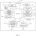
- FIG. 5 is a schematic diagram of a hardware structure of a terminal device for implementing the embodiments of this disclosure.
- the terminal device 500 includes but is not limited to components such as a radio frequency unit 501, a network module 502, an audio output unit 503, an input unit 504, a sensor 505, a display unit 506, a user input unit 507, an interface unit 508, a memory 509, a processor 510, and a power supply 511.
- a radio frequency unit 501 such as a radio frequency unit 501, a network module 502, an audio output unit 503, an input unit 504, a sensor 505, a display unit 506, a user input unit 507, an interface unit 508, a memory 509, a processor 510, and a power supply 511.
- a person skilled in the art can understand that the terminal device is not limited to the terminal device structure shown in FIG. 5 .
- the terminal device may include more or fewer components than those shown in the figure, or combine some of the components, or arrange the components differently.
- a network device and the terminal device can have consistent understanding in a random access procedure, ensuring that the terminal device can receive corresponding random access response messages with differentiation in a case that at least two random access types are supported, thereby ensuring subsequent correct data parsing and successful completion of the random access procedures.
- the radio frequency unit 501 may be configured to receive and transmit information, or to receive and transmit a signal in a call process, and specifically, after receiving downlink data from a base station, transmit the downlink data to the processor 510 for processing; and also transmit uplink data to the base station.
- the radio frequency unit 501 includes but is not limited to an antenna, at least one amplifier, a transceiver, a coupler, a low noise amplifier, a duplexer, and the like.
- the radio frequency unit 501 may further communicate with a network and other devices through a wireless communications system.
- the terminal device 500 further includes at least one sensor 505, for example, an optical sensor, a motion sensor, and other sensors.
- the optical sensor includes an ambient light sensor and a proximity sensor.
- the ambient light sensor may adjust brightness of a display panel 5061 based on intensity of ambient light.
- the proximity sensor may disable the display panel 5061 and/or backlight.
- an accelerometer sensor can detect magnitudes of accelerations in all directions (usually three axes), can detect the magnitude and direction of gravity when the mobile phone is in a static state, and can be applied to terminal device posture recognition (such as screen switching between portrait and landscape, related games, and magnetometer posture calibration), functions related to vibration recognition (such as pedometer and tapping), and the like.
- the sensor 505 may further include a fingerprint sensor, a pressure sensor, an iris sensor, a molecular sensor, a gyroscope, a barometer, a hygrometer, a thermometer, an infrared sensor, and the like. Details are not described herein.
- the user input unit 507 may be configured to receive input digit or character information, and generate key signal input that is related to user setting and function control of the terminal device.
- the user input unit 507 includes a touch panel 5071 and other input devices 5072.
- the touch panel 5071 is also referred to as a touchscreen, and may collect a touch operation of the user on or near the touch panel (for example, an operation performed on or near the touch panel 5071 by the user by using any appropriate object or accessory such as a finger or a stylus).
- the touch panel 5071 may include two parts: a touch detection apparatus and a touch controller.
- the touch detection apparatus detects a touch orientation of the user, and detects a signal brought by the touch operation, and transmits the signal to the touch controller.
- the touch controller receives touch information from the touch detection apparatus, converts the touch information into touch point coordinates, sends the touch point coordinates to the processor 510, and receives and executes a command sent by the processor 510.
- the touch panel 5071 may be implemented in a plurality of types, for example, as a resistive, capacitive, infrared, or surface acoustic wave touch panel.
- the user input unit 507 may further include the other input devices 5072.
- the other input devices 5072 may include but are not limited to a physical keyboard, a function key (for example, a volume control key or a power on/off key), a track ball, a mouse, and a joystick. Details are not described herein.
- the processor 510 is a control center of the terminal device, uses various interfaces and lines to connect all parts of the entire terminal device, and performs various functions and data processing of the terminal device by running or executing the software program and/or module stored in the memory 509 and invoking data stored in the memory 509, thereby performing overall monitoring on the terminal device.
- the processor 510 may include one or more processing units.
- the processor 510 may integrate an application processor and a modem processor.
- the application processor mainly processes an operating system, a user interface, an application program, and the like.
- the modem processor mainly processes wireless communication. It can be understood that the modem processor may alternatively not be integrated into the processor 510.
- the terminal device 500 may further include a power supply 511 (for example, a battery) that supplies power to the components.
- a power supply 511 for example, a battery
- the power supply 511 may be logically connected to the processor 510 by using a power management system, so as to implement functions such as charging management, discharging management, and power consumption management by using the power management system.
- terminal device 500 may further include some functional modules that are not shown. Details are not described herein.
- FIG. 6 is a schematic diagram of a hardware structure of a network device for implementing the embodiments of this disclosure.
- the network device 60 includes but is not limited to a bus 61, a transceiver 62, an antenna 63, a bus interface 64, a processor 65, and a memory 66.
- the network device 60 further includes a computer program stored in the memory 66 and capable of running on the processor 65.
- the computer program is executed by the processor 65, the following step is implemented: transmitting DCI to a terminal device based on a current random access type, where the DCI is used to schedule a random access response message corresponding to the current random access type.
- the transceiver 62 is configured to transmit and receive data under control of the processor 65.
- the bus 61 may include any quantity of interconnected buses and bridges, and the bus 61 connects various circuits that include one or more processors represented by the processor 65 and a memory represented by the memory 66.
- the bus 61 may further connect various other circuits, such as a peripheral device, a voltage regulator, and a power management circuit. These are common sense in the art, and therefore are not further described in this specification.
- the bus interface 64 provides an interface between the bus 61 and the transceiver 62.
- the transceiver 62 may be one element, or may be a plurality of elements, for example, a plurality of receivers and transmitters, and provides a unit for communicating with various other apparatuses on a transmission medium.
- Data processed by the processor 65 is transmitted on a wireless medium through the antenna 63. Further, the antenna 63 receives data and transmits the data to the processor 65.
- the processor 65 is responsible for managing the bus 61 and general processing, and may further provide various functions, including timing, a peripheral interface, voltage regulation, power management, and other control functions.
- the memory 66 may be used to store data for use by the processor 65 when the processor 65 performs an operation.
- An embodiment of this disclosure further provides a computer-readable storage medium, where the computer-readable storage medium stores a computer program, and when the computer program is executed by the processor, the processes of the foregoing information transmission method embodiment or the foregoing information detection method embodiment can be implemented, with the same technical effects achieved. To avoid repetition, details are not described herein again.
- the computer-readable storage medium is a read-only memory (Read-Only Memory, ROM), a random access memory (Random Access Memory, RAM), a magnetic disk, or an optical disc.
Landscapes
- Engineering & Computer Science (AREA)
- Computer Networks & Wireless Communication (AREA)
- Signal Processing (AREA)
- Mobile Radio Communication Systems (AREA)
- Communication Control (AREA)
Claims (15)
- Procédé de transmission d'informations, appliqué à un dispositif de réseau, comprenant : la transmission (101) d'informations de commande de liaison descendante, DCI, à un dispositif terminal sur la base d'un type d'accès aléatoire en cours, dans lequelles DCI sont utilisées pour planifier un message de réponse d'accès aléatoire correspondant au type d'accès aléatoire en cours ;caractérisé en ce queles DCI sont brouillées par une identité temporaire de réseau radio à accès aléatoire, RA-RNTI, et la RA-RNTI est associée au type d'accès aléatoire en cours ;la RA-RNTI est calculée à l'aide de la formule suivante :
 s_id est un indice de symbole de multiplexage par répartition orthogonale de la fréquence (OFDM) d'une ressource du domaine temporel du premier symbole d'un canal physique d'accès aléatoire (PRACH), t_id est un indice de créneau du premier créneau de la ressource du domaine temporel du PRACH, et f_id est un indice du domaine fréquentiel d'une occasion de PRACH, RO, sur la ressource du domaine temporel du PRACH ;A est l'une des valeurs numériques suivantes : un nombre naturel configuré par le dispositif de réseau, une valeur prédéfinie, une valeur numérique indiquée par le dispositif terminal et le nombre de créneaux dans une fenêtre temporelle prédéfinie ;B est l'une des valeurs numériques suivantes : un nombre naturel configuré par le dispositif de réseau, une valeur prédéfinie, une valeur numérique indiquée par le dispositif terminal et le nombre de RO pour le multiplexage par répartition en fréquence, FDM, sur la ressource du domaine temporel du PRACH ;ul_carrier_id est l'une des valeurs numériques suivantes : un nombre naturel configuré par le dispositif de réseau, une valeur prédéfinie et une valeur numérique indiquée par le dispositif terminal ;n1, n2, n3, n4 et n5 sont des coefficients prédéfinis ; etE_id est une variable associée au type d'accès aléatoire.
 - Procédé selon la revendication 1, dans lequel les DCI comprennent des informations d'indication, et les informations d'indication sont utilisées pour indiquer un type d'accès aléatoire correspondant au message de réponse d'accès aléatoire planifié par les DCI.
- Procédé selon la revendication 1, dans lequel, avant la transmission (101) d'informations de commande de liaison descendante, DCI, à un dispositif terminal sur la base d'un type d'accès aléatoire en cours, le procédé comprend en outre :transmettre au dispositif terminal des informations de configuration du canal de commande de liaison descendante physique (PDCCH), dans lequelles informations de configuration du PDCCH comprennent au moins deux types d'informations de configuration de l'espace de recherche, et chaque type d'informations de configuration de l'espace de recherche est configuré pour les DCI qui planifient des messages de réponse correspondant à un type d'accès aléatoire.
- Procédé selon la revendication 3, dans lequel la transmission (101) d'informations de commande de liaison descendante, DCI, à un dispositif terminal sur la base d'un type d'accès aléatoire en cours comprend :transmettre les DCI au dispositif terminal dans un espace de recherche cible, dans lequell'espace de recherche cible correspond au type d'accès aléatoire en cours.
- Procédé de détection d'informations, appliqué à un dispositif terminal, comprenant :effectuer (201) la détection des DCI cibles sur la base d'un type d'accès aléatoire en cours, dans lequelles DCI cibles sont utilisées pour programmer un message de réponse d'accès aléatoire correspondant au type d'accès aléatoire en cours ;caractérisé en ce quel'exécution (201) de la détection des DCI cibles sur la base d'un type d'accès aléatoire en cours comprend : l'exécution, sur la base du type d'accès aléatoire en cours, de la détection des DCI cibles brouillées par une RA-RNTI, la RA-RNTI étant associée au type d'accès aléatoire en cours ;la RA-RNTI est calculée à l'aide de la formule suivante :
 s_id est un indice de symbole d'OFDM d'une ressource du domaine temporel du premier symbole d'un PRACH, t_id est un indice de créneau du premier créneau de la ressource du domaine temporel du PRACH, et f_id est un indice du domaine fréquentiel d'une RO, sur la ressource du domaine temporel du PRACH ;A est l'une des valeurs numériques suivantes : un nombre naturel configuré par le dispositif de réseau, une valeur prédéfinie, une valeur numérique indiquée par le dispositif terminal et le nombre de créneaux dans une fenêtre temporelle prédéfinie ;B est l'une des valeurs numériques suivantes : un nombre naturel configuré par le dispositif de réseau, une valeur prédéfinie, une valeur numérique indiquée par le dispositif terminal et le nombre de RO pour FDM sur la ressource du domaine temporel du PRACH;ul_carrier_id est l'une des valeurs numériques suivantes : un nombre naturel configuré par le dispositif de réseau, une valeur prédéfinie et une valeur numérique indiquée par le dispositif terminal ;n1, n2, n3, n4 et n5 sont des coefficients prédéfinis ; etE_id est une variable associée au type d'accès aléatoire.
 - Procédé selon la revendication 5, dans lequel l'exécution (201) de la détection des DCI cibles sur la base d'un type d'accès aléatoire en cours comprend :exécuter une détection en aveugle des DCI ;juger, sur la base des informations d'indication comprises dans les DCI détectées en aveugle, si un message de réponse d'accès aléatoire planifié par les DCI détectées en aveugle correspond au type d'accès aléatoire en cours ; etdans le cas où le message de réponse à l'accès aléatoire planifié par les DCI détectées en aveugle correspond au type d'accès aléatoire en cours, déterminer que les DCI détectées en aveugle sont les DCI cibles ; dans lequelles informations d'indication sont utilisées pour indiquer un type d'accès aléatoire correspondant au message de réponse d'accès aléatoire programmé par les DCI détectées en aveugle.
- Procédé selon la revendication 5, dans lequel, avant d'effectuer (201) la détection des DCI cibles sur la base d'un type d'accès aléatoire en cours, le procédé comprend en outre :recevoir des informations de configuration de PDCCH d'un dispositif de réseau, dans lequelles informations de configuration du PDCCH comprennent au moins deux types d'informations de configuration de l'espace de recherche, et chaque type d'informations de configuration de l'espace de recherche est configuré pour les DCI qui planifient des messages de réponse correspondant à un type d'accès aléatoire.
- Dispositif de réseau (30), comprenant :un premier module de transmission (31), configuré pour transmettre les DCI à un dispositif terminal sur la base d'un type d'accès aléatoire en cours, dans lequelles DCI sont utilisées pour planifier un message de réponse d'accès aléatoire correspondant au type d'accès aléatoire en cours ;caractérisé en ce queles DCI sont brouillées par une RA-RNTI, et la RA-RNTI est associée au type d'accès aléatoire en cours ;la RA-RNTI est calculée à l'aide de la formule suivante :
 s_id est un indice de symbole d'OFDM d'une ressource du domaine temporel du premier symbole d'un PRACH, t_id est un indice de créneau du premier créneau de la ressource du domaine temporel du PRACH, et f_id est un indice du domaine fréquentiel d'une RO, sur la ressource du domaine temporel du PRACH ;A est l'une des valeurs numériques suivantes : un nombre naturel configuré par le dispositif de réseau, une valeur prédéfinie, une valeur numérique indiquée par le dispositif terminal et le nombre de créneaux dans une fenêtre temporelle prédéfinie ;B est l'une des valeurs numériques suivantes : un nombre naturel configuré par le dispositif de réseau, une valeur prédéfinie, une valeur numérique indiquée par le dispositif terminal et le nombre de RO pour FDM sur la ressource du domaine temporel du PRACH;ul_carrier_id est l'une des valeurs numériques suivantes : un nombre naturel configuré par le dispositif de réseau, une valeur prédéfinie et une valeur numérique indiquée par le dispositif terminal ;n1, n2, n3, n4 et n5 sont des coefficients prédéfinis ; etE_id est une variable associée au type d'accès aléatoire.
 - Dispositif de réseau (30) selon la revendication 8, dans lequel les DCI comprennent des informations d'indication, et les informations d'indication sont utilisées pour indiquer un type d'accès aléatoire correspondant au message de réponse d'accès aléatoire planifié par les DCI.
- Dispositif de réseau (30) selon la revendication 8, comprenant en outre :un second module de transmission, configuré pour transmettre des informations de configuration du PDCCH au dispositif terminal, dans lequelles informations de configuration du PDCCH comprennent au moins deux types d'informations de configuration de l'espace de recherche, et chaque type d'informations de configuration de l'espace de recherche est configuré pour les DCI qui planifient des messages de réponse correspondant à un type d'accès aléatoire.
- Dispositif de réseau (30) selon la revendication 10, dans lequel le premier module de transmission (31) est spécifiquement configuré pour :transmettre les DCI au dispositif terminal dans un espace de recherche cible, dans lequell'espace de recherche cible correspond au type d'accès aléatoire en cours.
- Dispositif terminal (40), comprenant :un module de détection (41), configuré pour effectuer la détection de DCI cibles sur la base d'un type d'accès aléatoire en cours, dans lequelles DCI cibles sont utilisées pour programmer un message de réponse d'accès aléatoire correspondant au type d'accès aléatoire en cours ;caractérisé en ce quele module de détection (41) est spécifiquement configuré pour : effectuer, sur la base du type d'accès aléatoire en cours, la détection des DCI cibles brouillées par une RA-RNTI, la RA-RNTI étant associée au type d'accès aléatoire en cours ;la RA-RNTI est calculée à l'aide de la formule suivante :
 s_id est un indice de symbole d'OFDM d'une ressource du domaine temporel du premier symbole d'un PRACH, t_id est un indice de créneau du premier créneau de la ressource du domaine temporel du PRACH, et f_id est un indice du domaine fréquentiel d'une RO, sur la ressource du domaine temporel du PRACH ;A est l'une des valeurs numériques suivantes : un nombre naturel configuré par le dispositif de réseau, une valeur prédéfinie, une valeur numérique indiquée par le dispositif terminal et le nombre de créneaux dans une fenêtre temporelle prédéfinie ;B est l'une des valeurs numériques suivantes : un nombre naturel configuré par le dispositif de réseau, une valeur prédéfinie, une valeur numérique indiquée par le dispositif terminal et le nombre de RO pour FDM sur la ressource du domaine temporel du PRACH;ul_carrier_id est l'une des valeurs numériques suivantes : un nombre naturel configuré par le dispositif de réseau, une valeur prédéfinie et une valeur numérique indiquée par le dispositif terminal ;n1, n2, n3, n4 et n5 sont des coefficients prédéfinis ; etE_id est une variable associée au type d'accès aléatoire.
 - Dispositif terminal (40) selon la revendication 12, dans lequel le module de détection (41) comprend :une unité de détection, configurée pour exécuter une détection aveugle des DCI ;une unité de jugement, configurée pour juger, sur la base des informations d'indication comprises dans les DCI détectées en aveugle, si un message de réponse d'accès aléatoire planifié par les DCI détectées en aveugle correspond au type d'accès aléatoire en cours ; etune unité de détermination configurée pour : dans le cas où le message de réponse à l'accès aléatoire planifié par les DCI détectées en aveugle correspond au type d'accès aléatoire en cours, déterminer que les DCI détectées en aveugle sont les DCI cibles ; dans lequelles informations d'indication sont utilisées pour indiquer un type d'accès aléatoire correspondant au message de réponse d'accès aléatoire programmé par les DCI détectées en aveugle.
- Dispositif terminal (40) selon la revendication 12, comprenant en outre :un module de réception, configuré pour recevoir des informations de configuration de PDCCH d'un dispositif de réseau, dans lequelles informations de configuration du PDCCH comprennent au moins deux types d'informations de configuration de l'espace de recherche, et chaque type d'informations de configuration de l'espace de recherche est configuré pour les DCI qui planifient des messages de réponse correspondant à un type d'accès aléatoire.
- Support de stockage lisible par ordinateur, dans lequel le support de stockage lisible par ordinateur stocke un programme informatique, et lorsque le programme informatique est exécuté par un processeur, les étapes du procédé de transmission d'informations selon l'une quelconque des revendications 1 à 4 ou les étapes du procédé de détection d'informations selon l'une quelconque des revendications 5 et 7 sont mises en oeuvre.
Applications Claiming Priority (2)
| Application Number | Priority Date | Filing Date | Title |
|---|---|---|---|
| CN201910093607.1A CN111278149B (zh) | 2019-01-30 | 2019-01-30 | 信息发送方法、信息检测方法、终端设备及网络设备 |
| PCT/CN2020/073780 WO2020156428A1 (fr) | 2019-01-30 | 2020-01-22 | Procédé d'envoi d'informations, procédé de détection d'informations, dispositif de terminal et dispositif de réseau |
Publications (3)
| Publication Number | Publication Date |
|---|---|
| EP3920632A1 EP3920632A1 (fr) | 2021-12-08 |
| EP3920632A4 EP3920632A4 (fr) | 2022-03-30 |
| EP3920632B1 true EP3920632B1 (fr) | 2023-12-20 |
Family
ID=70998564
Family Applications (1)
| Application Number | Title | Priority Date | Filing Date |
|---|---|---|---|
| EP20748554.1A Active EP3920632B1 (fr) | 2019-01-30 | 2020-01-22 | Procédé d'envoi d'informations, procédé de détection d'informations, dispositif de terminal et dispositif de réseau |
Country Status (14)
| Country | Link |
|---|---|
| US (1) | US11985712B2 (fr) |
| EP (1) | EP3920632B1 (fr) |
| JP (1) | JP2022523509A (fr) |
| KR (1) | KR102768165B1 (fr) |
| CN (1) | CN111278149B (fr) |
| AU (1) | AU2020214490B2 (fr) |
| BR (1) | BR112021014975A2 (fr) |
| CA (1) | CA3128281C (fr) |
| ES (1) | ES2968814T3 (fr) |
| HU (1) | HUE065192T2 (fr) |
| PH (1) | PH12021551835A1 (fr) |
| PT (1) | PT3920632T (fr) |
| SG (1) | SG11202108370QA (fr) |
| WO (1) | WO2020156428A1 (fr) |
Families Citing this family (10)
| Publication number | Priority date | Publication date | Assignee | Title |
|---|---|---|---|---|
| EP3949606B1 (fr) * | 2019-03-27 | 2024-11-20 | Telefonaktiebolaget LM Ericsson (publ) | Procédé et appareil de surveillance de pdcch dans une procédure d'accès aléatoire |
| CN111867130B (zh) * | 2019-04-30 | 2023-07-18 | 华为技术有限公司 | 一种随机接入方法、装置及存储介质 |
| BR112022026375A2 (pt) * | 2020-06-24 | 2023-03-14 | Beijing Xiaomi Mobile Software Co Ltd | Método e aparelho de transmissão de informações, dispositivo de comunicação, e, meio de armazenamento |
| JP7507242B2 (ja) * | 2020-08-25 | 2024-06-27 | 中興通訊股▲ふん▼有限公司 | 無線ネットワーク一時識別子に関連する方法および装置 |
| US12301488B2 (en) * | 2020-10-02 | 2025-05-13 | Samsung Electronics Co., Ltd. | Methods and apparatus for random access procedures with spatial settings |
| CN116602040A (zh) * | 2021-01-14 | 2023-08-15 | 华为技术有限公司 | 一种通信方法及装置 |
| CN115150967A (zh) * | 2021-03-31 | 2022-10-04 | 华为技术有限公司 | 一种随机接入方法及装置 |
| CN115515249B (zh) * | 2021-06-22 | 2025-05-27 | 华为技术有限公司 | 一种随机接入方法及装置 |
| CN115996477A (zh) * | 2021-10-20 | 2023-04-21 | 华为技术有限公司 | 一种通信方法及装置 |
| CN120239096A (zh) * | 2023-12-28 | 2025-07-01 | 维沃移动通信有限公司 | 资源类型确定方法、装置及相关产品 |
Family Cites Families (12)
| Publication number | Priority date | Publication date | Assignee | Title |
|---|---|---|---|---|
| IN2014CN03078A (fr) * | 2011-11-04 | 2015-07-03 | Intel Corp | |
| KR102252583B1 (ko) | 2014-11-07 | 2021-05-14 | 후아웨이 테크놀러지 컴퍼니 리미티드 | 물리 하향링크 제어채널 전송 방법, 기지국 장치, 및 사용자 장비 |
| US10536895B2 (en) * | 2015-05-13 | 2020-01-14 | Lg Electronics Inc. | Method and apparatus for performing initial access procedure for low cost user equipment in wireless communication system |
| EP3172856B1 (fr) * | 2015-09-25 | 2021-06-02 | LG Electronics Inc. | Procédé et équipement utilisateur permettant la réception d'informations de commande de liaison descendante, et procédé et station de base permettant l'émission d'informations de commande de liaison descendante |
| US10172162B2 (en) * | 2016-01-26 | 2019-01-01 | Lg Electronics Inc. | Method for performing a random access procedure in wireless communication system and a device therefor |
| CN107453840B (zh) * | 2016-05-30 | 2021-08-10 | 北京三星通信技术研究有限公司 | 一种资源的调度方法和设备 |
| CN107820318A (zh) * | 2016-09-10 | 2018-03-20 | 北京信威通信技术股份有限公司 | 一种发送信息的方法及装置 |
| CN108282901B (zh) | 2017-01-06 | 2019-08-09 | 电信科学技术研究院 | 一种随机接入响应方法和装置 |
| US10397958B2 (en) | 2017-03-17 | 2019-08-27 | Asustek Computer Inc. | Method and apparatus for backoff mechanism applied for random access procedure in a wireless communication system |
| WO2018174595A1 (fr) * | 2017-03-23 | 2018-09-27 | 엘지전자 주식회사 | Procédé de réalisation d'une procédure d'accès aléatoire et appareil associé |
| EP3596993B1 (fr) * | 2017-06-07 | 2021-08-25 | Samsung Electronics Co., Ltd. | Système et procédé d'identification d'une réponse d'accès aléatoire |
| WO2020146726A1 (fr) * | 2019-01-10 | 2020-07-16 | Apple Inc. | Procédure de repli pour rach en 2 étapes |
-
2019
- 2019-01-30 CN CN201910093607.1A patent/CN111278149B/zh active Active
-
2020
- 2020-01-22 SG SG11202108370QA patent/SG11202108370QA/en unknown
- 2020-01-22 AU AU2020214490A patent/AU2020214490B2/en active Active
- 2020-01-22 PH PH1/2021/551835A patent/PH12021551835A1/en unknown
- 2020-01-22 WO PCT/CN2020/073780 patent/WO2020156428A1/fr not_active Ceased
- 2020-01-22 HU HUE20748554A patent/HUE065192T2/hu unknown
- 2020-01-22 PT PT207485541T patent/PT3920632T/pt unknown
- 2020-01-22 BR BR112021014975-9A patent/BR112021014975A2/pt unknown
- 2020-01-22 CA CA3128281A patent/CA3128281C/fr active Active
- 2020-01-22 ES ES20748554T patent/ES2968814T3/es active Active
- 2020-01-22 JP JP2021544409A patent/JP2022523509A/ja active Pending
- 2020-01-22 KR KR1020217026700A patent/KR102768165B1/ko active Active
- 2020-01-22 EP EP20748554.1A patent/EP3920632B1/fr active Active
-
2021
- 2021-07-30 US US17/390,452 patent/US11985712B2/en active Active
Also Published As
| Publication number | Publication date |
|---|---|
| SG11202108370QA (en) | 2021-08-30 |
| AU2020214490A1 (en) | 2021-09-23 |
| WO2020156428A1 (fr) | 2020-08-06 |
| EP3920632A4 (fr) | 2022-03-30 |
| CA3128281A1 (fr) | 2020-08-06 |
| CA3128281C (fr) | 2023-10-31 |
| AU2020214490B2 (en) | 2022-11-24 |
| US20210360711A1 (en) | 2021-11-18 |
| KR20210119470A (ko) | 2021-10-05 |
| CN111278149B (zh) | 2022-02-08 |
| KR102768165B1 (ko) | 2025-02-13 |
| CN111278149A (zh) | 2020-06-12 |
| PH12021551835A1 (en) | 2022-03-21 |
| EP3920632A1 (fr) | 2021-12-08 |
| JP2022523509A (ja) | 2022-04-25 |
| ES2968814T3 (es) | 2024-05-14 |
| HUE065192T2 (hu) | 2024-05-28 |
| PT3920632T (pt) | 2024-01-11 |
| US11985712B2 (en) | 2024-05-14 |
| BR112021014975A2 (pt) | 2021-10-05 |
Similar Documents
| Publication | Publication Date | Title |
|---|---|---|
| EP3920632B1 (fr) | Procédé d'envoi d'informations, procédé de détection d'informations, dispositif de terminal et dispositif de réseau | |
| US12177781B2 (en) | Channel monitoring method, terminal, and network device | |
| US12035242B2 (en) | PDCCH monitoring method and terminal | |
| US12245059B2 (en) | Transmission method and communication device | |
| EP3876645B1 (fr) | Procédé de transmission de liaison montante, équipement utilisateur et dispositif côté réseau | |
| EP3952180A1 (fr) | Appareil et procédé de configuration d'espace de recherche, et dispositif de communication | |
| US12302348B2 (en) | Timing determination method and communication device | |
| EP3952552A1 (fr) | Procédé de transmission, dispositif terminal et dispositif côté réseau | |
| WO2020192547A1 (fr) | Procédé de transmission et de réception d'informations, terminal et dispositif côté réseau | |
| US12232106B2 (en) | Resource determining method, resource configuration method, terminal, and network device | |
| KR20200106178A (ko) | 검색 공간의 청취 정보 확정 방법 및 장치 | |
| EP3934146A1 (fr) | Procédé d'indication de ressource de transmission, procédé de transmission, dispositif réseau et terminal | |
| US20220279439A1 (en) | Method for secondary cell dormancy indication and communication device | |
| EP3809776B1 (fr) | Procédé d'attribution de ressources dans le domaine temporel pdsch, terminal et support d'informations lisible par ordinateur | |
| RU2783045C1 (ru) | Способ передачи информации, способ обнаружения информации, оконечное устройство и сетевое устройство | |
| US12133264B2 (en) | Method for selecting random access request resource, terminal, and network device | |
| CN110768764A (zh) | 信息传输方法及终端 | |
| HK40063757A (en) | Pdcch monitoring method and terminal | |
| HK40067214A (en) | Method for selecting random access request resource, terminal, and network device | |
| HK40072815B (en) | Resource determination method, resource configuration method, terminal, and network device | |
| HK40061137A (en) | Channel monitoring method, terminal and network device | |
| HK40061990A (en) | Transmission method, terminal device, and network-side device |
Legal Events
| Date | Code | Title | Description |
|---|---|---|---|
| STAA | Information on the status of an ep patent application or granted ep patent |
Free format text: STATUS: THE INTERNATIONAL PUBLICATION HAS BEEN MADE |
|
| PUAI | Public reference made under article 153(3) epc to a published international application that has entered the european phase |
Free format text: ORIGINAL CODE: 0009012 |
|
| STAA | Information on the status of an ep patent application or granted ep patent |
Free format text: STATUS: REQUEST FOR EXAMINATION WAS MADE |
|
| 17P | Request for examination filed |
Effective date: 20210823 |
|
| AK | Designated contracting states |
Kind code of ref document: A1 Designated state(s): AL AT BE BG CH CY CZ DE DK EE ES FI FR GB GR HR HU IE IS IT LI LT LU LV MC MK MT NL NO PL PT RO RS SE SI SK SM TR |
|
| A4 | Supplementary search report drawn up and despatched |
Effective date: 20220225 |
|
| RIC1 | Information provided on ipc code assigned before grant |
Ipc: H04W 74/00 20090101ALI20220221BHEP Ipc: H04W 74/08 20090101ALI20220221BHEP Ipc: H04W 72/12 20090101AFI20220221BHEP |
|
| DAV | Request for validation of the european patent (deleted) | ||
| DAX | Request for extension of the european patent (deleted) | ||
| GRAP | Despatch of communication of intention to grant a patent |
Free format text: ORIGINAL CODE: EPIDOSNIGR1 |
|
| STAA | Information on the status of an ep patent application or granted ep patent |
Free format text: STATUS: GRANT OF PATENT IS INTENDED |
|
| INTG | Intention to grant announced |
Effective date: 20231013 |
|
| GRAS | Grant fee paid |
Free format text: ORIGINAL CODE: EPIDOSNIGR3 |
|
| GRAA | (expected) grant |
Free format text: ORIGINAL CODE: 0009210 |
|
| STAA | Information on the status of an ep patent application or granted ep patent |
Free format text: STATUS: THE PATENT HAS BEEN GRANTED |
|
| AK | Designated contracting states |
Kind code of ref document: B1 Designated state(s): AL AT BE BG CH CY CZ DE DK EE ES FI FR GB GR HR HU IE IS IT LI LT LU LV MC MK MT NL NO PL PT RO RS SE SI SK SM TR |
|
| REG | Reference to a national code |
Ref country code: GB Ref legal event code: FG4D |
|
| REG | Reference to a national code |
Ref country code: CH Ref legal event code: EP |
|
| REG | Reference to a national code |
Ref country code: DE Ref legal event code: R096 Ref document number: 602020023104 Country of ref document: DE |
|
| REG | Reference to a national code |
Ref country code: PT Ref legal event code: SC4A Ref document number: 3920632 Country of ref document: PT Date of ref document: 20240111 Kind code of ref document: T Free format text: AVAILABILITY OF NATIONAL TRANSLATION Effective date: 20240108 |
|
| REG | Reference to a national code |
Ref country code: IE Ref legal event code: FG4D |
|
| REG | Reference to a national code |
Ref country code: NL Ref legal event code: FP |
|
| REG | Reference to a national code |
Ref country code: SK Ref legal event code: T3 Ref document number: E 43270 Country of ref document: SK |
|
| PG25 | Lapsed in a contracting state [announced via postgrant information from national office to epo] |
Ref country code: GR Free format text: LAPSE BECAUSE OF FAILURE TO SUBMIT A TRANSLATION OF THE DESCRIPTION OR TO PAY THE FEE WITHIN THE PRESCRIBED TIME-LIMIT Effective date: 20240321 |
|
| REG | Reference to a national code |
Ref country code: LT Ref legal event code: MG9D |
|
| PG25 | Lapsed in a contracting state [announced via postgrant information from national office to epo] |
Ref country code: LT Free format text: LAPSE BECAUSE OF FAILURE TO SUBMIT A TRANSLATION OF THE DESCRIPTION OR TO PAY THE FEE WITHIN THE PRESCRIBED TIME-LIMIT Effective date: 20231220 |
|
| PG25 | Lapsed in a contracting state [announced via postgrant information from national office to epo] |
Ref country code: LT Free format text: LAPSE BECAUSE OF FAILURE TO SUBMIT A TRANSLATION OF THE DESCRIPTION OR TO PAY THE FEE WITHIN THE PRESCRIBED TIME-LIMIT Effective date: 20231220 Ref country code: GR Free format text: LAPSE BECAUSE OF FAILURE TO SUBMIT A TRANSLATION OF THE DESCRIPTION OR TO PAY THE FEE WITHIN THE PRESCRIBED TIME-LIMIT Effective date: 20240321 Ref country code: FI Free format text: LAPSE BECAUSE OF FAILURE TO SUBMIT A TRANSLATION OF THE DESCRIPTION OR TO PAY THE FEE WITHIN THE PRESCRIBED TIME-LIMIT Effective date: 20231220 Ref country code: BG Free format text: LAPSE BECAUSE OF FAILURE TO SUBMIT A TRANSLATION OF THE DESCRIPTION OR TO PAY THE FEE WITHIN THE PRESCRIBED TIME-LIMIT Effective date: 20240320 |
|
| REG | Reference to a national code |
Ref country code: ES Ref legal event code: FG2A Ref document number: 2968814 Country of ref document: ES Kind code of ref document: T3 Effective date: 20240514 |
|
| REG | Reference to a national code |
Ref country code: AT Ref legal event code: MK05 Ref document number: 1643563 Country of ref document: AT Kind code of ref document: T Effective date: 20231220 |
|
| REG | Reference to a national code |
Ref country code: HU Ref legal event code: AG4A Ref document number: E065192 Country of ref document: HU |
|
| PG25 | Lapsed in a contracting state [announced via postgrant information from national office to epo] |
Ref country code: SE Free format text: LAPSE BECAUSE OF FAILURE TO SUBMIT A TRANSLATION OF THE DESCRIPTION OR TO PAY THE FEE WITHIN THE PRESCRIBED TIME-LIMIT Effective date: 20231220 Ref country code: RS Free format text: LAPSE BECAUSE OF FAILURE TO SUBMIT A TRANSLATION OF THE DESCRIPTION OR TO PAY THE FEE WITHIN THE PRESCRIBED TIME-LIMIT Effective date: 20231220 Ref country code: NO Free format text: LAPSE BECAUSE OF FAILURE TO SUBMIT A TRANSLATION OF THE DESCRIPTION OR TO PAY THE FEE WITHIN THE PRESCRIBED TIME-LIMIT Effective date: 20240320 Ref country code: LV Free format text: LAPSE BECAUSE OF FAILURE TO SUBMIT A TRANSLATION OF THE DESCRIPTION OR TO PAY THE FEE WITHIN THE PRESCRIBED TIME-LIMIT Effective date: 20231220 Ref country code: HR Free format text: LAPSE BECAUSE OF FAILURE TO SUBMIT A TRANSLATION OF THE DESCRIPTION OR TO PAY THE FEE WITHIN THE PRESCRIBED TIME-LIMIT Effective date: 20231220 |
|
| PG25 | Lapsed in a contracting state [announced via postgrant information from national office to epo] |
Ref country code: IS Free format text: LAPSE BECAUSE OF FAILURE TO SUBMIT A TRANSLATION OF THE DESCRIPTION OR TO PAY THE FEE WITHIN THE PRESCRIBED TIME-LIMIT Effective date: 20240420 |
|
| PG25 | Lapsed in a contracting state [announced via postgrant information from national office to epo] |
Ref country code: CZ Free format text: LAPSE BECAUSE OF FAILURE TO SUBMIT A TRANSLATION OF THE DESCRIPTION OR TO PAY THE FEE WITHIN THE PRESCRIBED TIME-LIMIT Effective date: 20231220 Ref country code: AT Free format text: LAPSE BECAUSE OF FAILURE TO SUBMIT A TRANSLATION OF THE DESCRIPTION OR TO PAY THE FEE WITHIN THE PRESCRIBED TIME-LIMIT Effective date: 20231220 |
|
| PG25 | Lapsed in a contracting state [announced via postgrant information from national office to epo] |
Ref country code: SM Free format text: LAPSE BECAUSE OF FAILURE TO SUBMIT A TRANSLATION OF THE DESCRIPTION OR TO PAY THE FEE WITHIN THE PRESCRIBED TIME-LIMIT Effective date: 20231220 Ref country code: RO Free format text: LAPSE BECAUSE OF FAILURE TO SUBMIT A TRANSLATION OF THE DESCRIPTION OR TO PAY THE FEE WITHIN THE PRESCRIBED TIME-LIMIT Effective date: 20231220 Ref country code: IS Free format text: LAPSE BECAUSE OF FAILURE TO SUBMIT A TRANSLATION OF THE DESCRIPTION OR TO PAY THE FEE WITHIN THE PRESCRIBED TIME-LIMIT Effective date: 20240420 Ref country code: EE Free format text: LAPSE BECAUSE OF FAILURE TO SUBMIT A TRANSLATION OF THE DESCRIPTION OR TO PAY THE FEE WITHIN THE PRESCRIBED TIME-LIMIT Effective date: 20231220 Ref country code: CZ Free format text: LAPSE BECAUSE OF FAILURE TO SUBMIT A TRANSLATION OF THE DESCRIPTION OR TO PAY THE FEE WITHIN THE PRESCRIBED TIME-LIMIT Effective date: 20231220 Ref country code: AT Free format text: LAPSE BECAUSE OF FAILURE TO SUBMIT A TRANSLATION OF THE DESCRIPTION OR TO PAY THE FEE WITHIN THE PRESCRIBED TIME-LIMIT Effective date: 20231220 |
|
| PG25 | Lapsed in a contracting state [announced via postgrant information from national office to epo] |
Ref country code: PL Free format text: LAPSE BECAUSE OF FAILURE TO SUBMIT A TRANSLATION OF THE DESCRIPTION OR TO PAY THE FEE WITHIN THE PRESCRIBED TIME-LIMIT Effective date: 20231220 |
|
| PG25 | Lapsed in a contracting state [announced via postgrant information from national office to epo] |
Ref country code: PL Free format text: LAPSE BECAUSE OF FAILURE TO SUBMIT A TRANSLATION OF THE DESCRIPTION OR TO PAY THE FEE WITHIN THE PRESCRIBED TIME-LIMIT Effective date: 20231220 |
|
| REG | Reference to a national code |
Ref country code: CH Ref legal event code: PL |
|
| PG25 | Lapsed in a contracting state [announced via postgrant information from national office to epo] |
Ref country code: LU Free format text: LAPSE BECAUSE OF NON-PAYMENT OF DUE FEES Effective date: 20240122 |
|
| REG | Reference to a national code |
Ref country code: DE Ref legal event code: R097 Ref document number: 602020023104 Country of ref document: DE |
|
| PG25 | Lapsed in a contracting state [announced via postgrant information from national office to epo] |
Ref country code: LU Free format text: LAPSE BECAUSE OF NON-PAYMENT OF DUE FEES Effective date: 20240122 Ref country code: MC Free format text: LAPSE BECAUSE OF FAILURE TO SUBMIT A TRANSLATION OF THE DESCRIPTION OR TO PAY THE FEE WITHIN THE PRESCRIBED TIME-LIMIT Effective date: 20231220 |
|
| PG25 | Lapsed in a contracting state [announced via postgrant information from national office to epo] |
Ref country code: DK Free format text: LAPSE BECAUSE OF FAILURE TO SUBMIT A TRANSLATION OF THE DESCRIPTION OR TO PAY THE FEE WITHIN THE PRESCRIBED TIME-LIMIT Effective date: 20231220 |
|
| PG25 | Lapsed in a contracting state [announced via postgrant information from national office to epo] |
Ref country code: BE Free format text: LAPSE BECAUSE OF NON-PAYMENT OF DUE FEES Effective date: 20240131 |
|
| PG25 | Lapsed in a contracting state [announced via postgrant information from national office to epo] |
Ref country code: CH Free format text: LAPSE BECAUSE OF NON-PAYMENT OF DUE FEES Effective date: 20240131 |
|
| PLBE | No opposition filed within time limit |
Free format text: ORIGINAL CODE: 0009261 |
|
| STAA | Information on the status of an ep patent application or granted ep patent |
Free format text: STATUS: NO OPPOSITION FILED WITHIN TIME LIMIT |
|
| PG25 | Lapsed in a contracting state [announced via postgrant information from national office to epo] |
Ref country code: SI Free format text: LAPSE BECAUSE OF FAILURE TO SUBMIT A TRANSLATION OF THE DESCRIPTION OR TO PAY THE FEE WITHIN THE PRESCRIBED TIME-LIMIT Effective date: 20231220 |
|
| PG25 | Lapsed in a contracting state [announced via postgrant information from national office to epo] |
Ref country code: SI Free format text: LAPSE BECAUSE OF FAILURE TO SUBMIT A TRANSLATION OF THE DESCRIPTION OR TO PAY THE FEE WITHIN THE PRESCRIBED TIME-LIMIT Effective date: 20231220 Ref country code: DK Free format text: LAPSE BECAUSE OF FAILURE TO SUBMIT A TRANSLATION OF THE DESCRIPTION OR TO PAY THE FEE WITHIN THE PRESCRIBED TIME-LIMIT Effective date: 20231220 Ref country code: CH Free format text: LAPSE BECAUSE OF NON-PAYMENT OF DUE FEES Effective date: 20240131 Ref country code: BE Free format text: LAPSE BECAUSE OF NON-PAYMENT OF DUE FEES Effective date: 20240131 |
|
| REG | Reference to a national code |
Ref country code: BE Ref legal event code: MM Effective date: 20240131 |
|
| 26N | No opposition filed |
Effective date: 20240923 |
|
| PG25 | Lapsed in a contracting state [announced via postgrant information from national office to epo] |
Ref country code: IE Free format text: LAPSE BECAUSE OF NON-PAYMENT OF DUE FEES Effective date: 20240122 |
|
| PG25 | Lapsed in a contracting state [announced via postgrant information from national office to epo] |
Ref country code: IE Free format text: LAPSE BECAUSE OF NON-PAYMENT OF DUE FEES Effective date: 20240122 |
|
| PG25 | Lapsed in a contracting state [announced via postgrant information from national office to epo] |
Ref country code: CY Free format text: LAPSE BECAUSE OF FAILURE TO SUBMIT A TRANSLATION OF THE DESCRIPTION OR TO PAY THE FEE WITHIN THE PRESCRIBED TIME-LIMIT; INVALID AB INITIO Effective date: 20200122 |
|
| PG25 | Lapsed in a contracting state [announced via postgrant information from national office to epo] |
Ref country code: TR Free format text: LAPSE BECAUSE OF FAILURE TO SUBMIT A TRANSLATION OF THE DESCRIPTION OR TO PAY THE FEE WITHIN THE PRESCRIBED TIME-LIMIT Effective date: 20231220 |
|
| PGFP | Annual fee paid to national office [announced via postgrant information from national office to epo] |
Ref country code: GB Payment date: 20251204 Year of fee payment: 7 |
|
| PGFP | Annual fee paid to national office [announced via postgrant information from national office to epo] |
Ref country code: FR Payment date: 20251128 Year of fee payment: 7 Ref country code: NL Payment date: 20251215 Year of fee payment: 7 |
|
| PGFP | Annual fee paid to national office [announced via postgrant information from national office to epo] |
Ref country code: SK Payment date: 20251212 Year of fee payment: 7 |
|
| PGFP | Annual fee paid to national office [announced via postgrant information from national office to epo] |
Ref country code: HU Payment date: 20260112 Year of fee payment: 7 |
|
| PGFP | Annual fee paid to national office [announced via postgrant information from national office to epo] |
Ref country code: ES Payment date: 20260212 Year of fee payment: 7 |
|
| PGFP | Annual fee paid to national office [announced via postgrant information from national office to epo] |
Ref country code: DE Payment date: 20251203 Year of fee payment: 7 |
|
| PGFP | Annual fee paid to national office [announced via postgrant information from national office to epo] |
Ref country code: IT Payment date: 20251219 Year of fee payment: 7 |
|
| PGFP | Annual fee paid to national office [announced via postgrant information from national office to epo] |
Ref country code: PT Payment date: 20260116 Year of fee payment: 7 |