EP3920681B1 - Conveyor device for agricultural machinery and agricultural machinery comprising said device - Google Patents
Conveyor device for agricultural machinery and agricultural machinery comprising said device Download PDFInfo
- Publication number
- EP3920681B1 EP3920681B1 EP21711360.4A EP21711360A EP3920681B1 EP 3920681 B1 EP3920681 B1 EP 3920681B1 EP 21711360 A EP21711360 A EP 21711360A EP 3920681 B1 EP3920681 B1 EP 3920681B1
- Authority
- EP
- European Patent Office
- Prior art keywords
- pulleys
- conveyor device
- pulley
- conveyor
- lateral
- Prior art date
- Legal status (The legal status is an assumption and is not a legal conclusion. Google has not performed a legal analysis and makes no representation as to the accuracy of the status listed.)
- Active
Links
Images


Classifications
-
- B—PERFORMING OPERATIONS; TRANSPORTING
- B65—CONVEYING; PACKING; STORING; HANDLING THIN OR FILAMENTARY MATERIAL
- B65G—TRANSPORT OR STORAGE DEVICES, e.g. CONVEYORS FOR LOADING OR TIPPING, SHOP CONVEYOR SYSTEMS OR PNEUMATIC TUBE CONVEYORS
- B65G15/00—Conveyors having endless load-conveying surfaces, i.e. belts and like continuous members, to which tractive effort is transmitted by means other than endless driving elements of similar configuration
- B65G15/30—Belts or like endless load-carriers
- B65G15/32—Belts or like endless load-carriers made of rubber or plastics
- B65G15/42—Belts or like endless load-carriers made of rubber or plastics having ribs, ridges, or other surface projections
-
- B—PERFORMING OPERATIONS; TRANSPORTING
- B65—CONVEYING; PACKING; STORING; HANDLING THIN OR FILAMENTARY MATERIAL
- B65G—TRANSPORT OR STORAGE DEVICES, e.g. CONVEYORS FOR LOADING OR TIPPING, SHOP CONVEYOR SYSTEMS OR PNEUMATIC TUBE CONVEYORS
- B65G15/00—Conveyors having endless load-conveying surfaces, i.e. belts and like continuous members, to which tractive effort is transmitted by means other than endless driving elements of similar configuration
- B65G15/30—Belts or like endless load-carriers
- B65G15/50—Endless load-carriers consisting of a series of parallel ropes or belt strips
- B65G15/52—Endless load-carriers consisting of a series of parallel ropes or belt strips interconnected by transverse slats
-
- A—HUMAN NECESSITIES
- A01—AGRICULTURE; FORESTRY; ANIMAL HUSBANDRY; HUNTING; TRAPPING; FISHING
- A01D—HARVESTING; MOWING
- A01D61/00—Elevators or conveyors for binders or combines
- A01D61/02—Endless belts
-
- B—PERFORMING OPERATIONS; TRANSPORTING
- B65—CONVEYING; PACKING; STORING; HANDLING THIN OR FILAMENTARY MATERIAL
- B65G—TRANSPORT OR STORAGE DEVICES, e.g. CONVEYORS FOR LOADING OR TIPPING, SHOP CONVEYOR SYSTEMS OR PNEUMATIC TUBE CONVEYORS
- B65G15/00—Conveyors having endless load-conveying surfaces, i.e. belts and like continuous members, to which tractive effort is transmitted by means other than endless driving elements of similar configuration
- B65G15/30—Belts or like endless load-carriers
- B65G15/32—Belts or like endless load-carriers made of rubber or plastics
- B65G15/42—Belts or like endless load-carriers made of rubber or plastics having ribs, ridges, or other surface projections
- B65G15/44—Belts or like endless load-carriers made of rubber or plastics having ribs, ridges, or other surface projections for impelling the loads
-
- B—PERFORMING OPERATIONS; TRANSPORTING
- B65—CONVEYING; PACKING; STORING; HANDLING THIN OR FILAMENTARY MATERIAL
- B65G—TRANSPORT OR STORAGE DEVICES, e.g. CONVEYORS FOR LOADING OR TIPPING, SHOP CONVEYOR SYSTEMS OR PNEUMATIC TUBE CONVEYORS
- B65G23/00—Driving gear for endless conveyors; Belt- or chain-tensioning arrangements
- B65G23/44—Belt or chain tensioning arrangements
-
- B—PERFORMING OPERATIONS; TRANSPORTING
- B65—CONVEYING; PACKING; STORING; HANDLING THIN OR FILAMENTARY MATERIAL
- B65G—TRANSPORT OR STORAGE DEVICES, e.g. CONVEYORS FOR LOADING OR TIPPING, SHOP CONVEYOR SYSTEMS OR PNEUMATIC TUBE CONVEYORS
- B65G23/00—Driving gear for endless conveyors; Belt- or chain-tensioning arrangements
- B65G23/02—Belt- or chain-engaging elements
- B65G23/04—Drums, rollers, or wheels
- B65G23/06—Drums, rollers, or wheels with projections engaging abutments on belts or chains, e.g. sprocket wheels
Definitions
- the present invention relates to a conveyor device and to agricultural machinery comprising said device.
- the present invention finds its main application in the moving/handling sector, and in particular in the production of handling systems for agricultural machinery.
- product handling systems are often used to convey freshly harvested agricultural products into specific machinery or to unload them in predetermined areas where they must then be collected or processed again.
- swathers that is agricultural machinery that collects already cut/mowed agricultural products from the field and arranges them in orderly rows, called swaths, in order to favour drying and facilitate collection thereof.
- this machinery is equipped with both pick-up members and conveyor devices operatively arranged downstream of the collection members and generally oriented so as to move the products transversely to the direction of movement and collection.
- Conveyor devices are usually of two types, i.e., belt or screw conveyors.
- belt conveyor devices are more widely used for their flexibility and lightness, which facilitate their positioning in the machinery.
- the belt is of the modular type and has a plurality of cross bars which are partly used to constrain the modules together.
- roller handling system entails some technical drawbacks, especially in terms of adherence, guiding and cleaning, which in the agricultural sector is often a critical factor for the functionality and reliability of the machinery.
- the object of the present invention is therefore to provide a conveyor device and agricultural machinery, which overcome the above-mentioned drawbacks of the prior art.
- Another object of the present invention is also to provide agricultural machinery equipped with a highly efficient and inexpensive handling/unloading system.
- the conveyor device comprises a conveyor belt continuously movable between two rotation axes.
- a first axis is preferably provided with at least two first pulleys rotating coaxially around a first rotation axis.
- Said first pulleys are spaced apart along said first rotation axis by a first distance (preferably equal to a width of the belt).
- a second axis is preferably provided with at least two second pulleys rotating coaxially around a second rotation axis.
- Said second pulleys are spaced apart along said second rotation axis by a second distance.
- the first and second distances are equal to each other.
- Each first pulley is aligned with a corresponding second pulley along a direction of movement of the conveyor device.
- the conveyor device further comprises a conveyor belt extending between said first and second axes and wrapped at least around said first and second pulleys.
- the conveyor belt is therefore moved by the pulleys along a direction of movement determined by the direction of rotation of the same.
- the conveyor belt is continuously movable between a transport section, upper in use, and a return section, lower in use.
- the conveyor belt comprises a substantially flat base body preferably made of rubberised cloth and having a first face, inner in use, and a second face, outer in use.
- This base body extends longitudinally along the direction of movement (wrapped around the first and second axes) and is provided with two lateral sides.
- the lateral sides delimit the base body transversely, preferably orthogonally to the direction of movement.
- the base body comprises a support central zone extending along the direction of movement and interposed between two traction lateral zones.
- the lateral zones are therefore adjacent to (and delimited by) lateral sides.
- the central zone has a smaller thickness than the two lateral zones.
- At least one lateral zone comprises at least one traction body projecting from said first face and couplable to a first pulley and to the respective second pulley for moving the conveyor belt.
- both lateral zones comprise a respective traction body.
- the traction body is made in one piece with (preferably vulcanized to) the respective lateral zone.
- the entire section of the conveyor belt is made in one piece, with the lateral zones engaging the pulleys, subjected to traction and guided therein by the traction body, and the central zone solely assigned to support the material.
- the traction body of at least one lateral zone is defined by a plurality of teeth made in one piece with the base body.
- Said teeth project from said first (inner) face and are arranged in succession along the direction of movement in order to engage at least a first pulley and the respective second pulley.
- the traction body preferably defines a toothed belt made in one piece with (preferably vulcanized to) the base body.
- the traction body of the other lateral zone also comprises a plurality of teeth arranged in succession along both lateral sides, so as to engage both the first pulleys and the respective second pulleys.
- the plurality of teeth preferably defines two lateral belts vulcanized to the respective lateral zone and provided with respective rows/successions of teeth projecting from the first face and aligned with respective grooves of the pulleys.
- the base body could comprise a single toothed belt at one lateral zone, with the other lateral zone moved solely by friction by the respective pulleys.
- the conveyor belt comprises a plurality of cross bars extending transversely to said direction of movement between the lateral zones (in particular from one to the other).
- the cross bars project from the second face of the base body.
- the conveyor belt also integrates the teeth that allow the use of a pulley handling system inside the same base body yet at the same time being reliable and light.
- first and second pulleys have respective diameters (preferably equal to each other) and said cross bars are spaced apart along the direction of movement by a predetermined distance "p".
- the distance "p" is quantitatively less than or equal to 2/3 ⁇ (d/2), wherein “d” corresponds to the smaller diameter of the first and second pulleys.
- the conveyor device comprises at least one longitudinal guide extending along said movement direction and facing the first face of the base body at said first section.
- the guide provides longitudinal support to the belt during movement in the transport section.
- the device comprises at least two longitudinal guides facing the first face of the base body at said lateral zones.
- each lateral zone preferably has an external resistant band (i.e., adjacent to the lateral side) where the traction body is located, and a sliding band, which is internal and is slidingly joined to the respective longitudinal guide when in the transport section.
- the numeral 1 indicates a conveyor device according to the present invention.
- the conveyor device 1 is therefore a belt-type product handling device configured to move the products on its own upper (i.e., exposed) surface by translation of the belt, which is controlled by a handling unit.
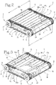
- the conveyor device 1 comprises a first 2 and a second rotating axis 3 around which a conveyor belt 4 is wrapped.
- the first axis 2 is provided with at least two first pulleys 5 rotating coaxially around a first rotation axis "A".
- Said first pulleys 5 are spaced apart along said first rotation axis "A" by a first distance "D1".
- the second axis 3 is provided with at least two second pulleys 6 rotating coaxially around a second rotation axis "B".
- Said second pulleys 6 are spaced apart along said second rotation axis "B" by a second distance "D2".
- the first "D1" and the second distance “D2" are equal to each other and substantially correspond to a width of the conveyor belt 4.
- each first pulley 5 is aligned with a corresponding second pulley 6 along a direction of movement "M" of the conveyor device 1.
- the first rotation axis "A" is, in use, at the same height (i.e., the height with respect to a supporting surface) as the second rotation axis "B".
- the conveyor belt 4 has a substantially horizontal direction of movement "M".
- each first 2 or second axis 3 could also be more than two, depending on the type and size of the conveyor device 1.
- the conveyor belt 4 extends between the first “A” and the second axis "B” and is (partially) wrapped around said first 5 and second pulleys 6.
- the conveyor belt 4 comprises a substantially flat base body 7 extending between the two axes 2, 3, and movable back and forth around them.
- the conveyor belt 4 in use, has an upper transport section 11a and a lower return section 11b.
- the base body 7 is made of rubberised cloth and has a first face 7a, inner in use, and a second face 7b, outer in use.
- rubberised cloth is used herein to define an element consisting essentially of a cloth or fabric coated, on one or both faces, with a rubber layer.
- the base body has a core made of mesh fabric, preferably of a material suitable for supporting heavy loads such as, for example, nylon, polyester, polyamide fibres, or other material.
- the coating is made, preferably but not necessarily on both faces, of a rubber, preferably a styrene-butadiene copolymer (or SBR rubber).
- the coating is asymmetrical, i.e., greater (thicker) at the second (outer) face 7b, whereas on the first face 7a it is thinner (if present), enough to leave the fabric mesh visible and sensitive to the touch.
- the base body 7 extends along the (longitudinal) movement direction and is transversely delimited by two lateral sides 7c.
- the distance between the two lateral sides 7c corresponds to a width of the conveyor belt 4.
- the base body 7 comprises a support central zone 10a extending along the direction of movement "M" and interposed between two traction lateral zones 10b.
- the two lateral zones 10b are therefore adjacent to (and externally delimited by) the lateral sides 7c of the base body 7.
- the central 10a and lateral zones 10b are made in one piece (i.e., in a single piece).
- the conveyor belt 4 (in particular the base body 7) is of the modular type and comprises a plurality of modules 8 arranged in series and joined at respective end edges 8a.
- this allows the length of the conveyor belt 4 to be changed at will by modifying the number of modules 8.
- Each module 8 therefore extends in a planar manner and is peripherally delimited by the two end edges 8a and by two lateral edges 8b, defining respective portions of the lateral sides 7c of the base body 7.
- the modules 8 are connected to each other through suitable joints.
- the conveyor belt 4 (in particular the base body 7) could be substantially monolithic, i.e., defined by a single band of material extending between two ends joined together to define the annular (or closed) path of the belt.
- At least one lateral zone 10b comprises at least one traction body 19, which is made in one piece with the respective lateral zone 10b, projects from said first face 7a and can be coupled to a first pulley 5 and to the respective second pulley 6 for moving the conveyor belt 4.
- both lateral zones 10b comprise a respective traction body 19.
- the traction body 19 of at least one lateral zone 10a comprises a plurality of teeth 9 made in one piece with the lateral zone 10a.
- said teeth 9 are vulcanized to the base body 7.
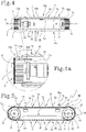
- the traction body 19 of at least one lateral zone 10b is preferably defined by a succession of teeth 9 projecting from the first face 7a and arranged along the respective lateral side 7c, so as to engage a first pulley 5 and the respective second pulley 6.
- the traction body 19 of the other lateral zone 10b is also defined by a succession of teeth 9 projecting from the first face 7a and arranged along the respective lateral side 7c, so as to engage the other first pulley 5 and the respective second pulley 6.
- this increases the traction and makes the system more reliable.
- the base body 7 (or the conveyor belt 4) could comprise a succession of teeth 9 at one lateral zone 10b without any further traction body projecting from the other; in this case, the "second" lateral zone 10b would be moved by friction by a pair of non-grooved pulleys.
- Each row has an orderly succession of teeth 9 spaced by a constant distance.
- each tooth 9 in one row is aligned, orthogonally to the direction of movement, with one tooth 9 in the other row.
- this allows the pulleys 5, 6 to keep a balanced traction on the conveyor belt 4.
- first 5 and/or second pulleys 6 in turn, have a plurality of teeth (or grooves) shaped to receive the teeth 9 of the conveyor belt 4 and to exert traction thereon.
- the first pulleys 5 are toothed so as to engage the traction body 9 of the conveyor belt 4.
- the second pulleys 6 are grooved, provided with a circumferential groove 6a in which the teeth 9 of the conveyor belt 4 are housed.
- the distance "pt" existing between two successive teeth 9 is comprised between 20 and 60 mm, more preferably between 25 and 35 mm. In the illustrated embodiment, this distance is approximately 31 mm.
- the teeth preferably have a height less than the width, where "height” refers to the dimension of the tooth 9 calculated moving away from the first face 7a of the base body 7, and “width” refers to the dimension of the tooth 9 calculated parallel to the rotation axes "A", "B” of the first 2 and the second axis 3.
- the shear stress given by the traction is well distributed and the bending moment generated at the base of the tooth is reduced.
- the depth of the tooth 9, i.e., the dimension thereof calculated along the direction of movement, is also greater than the height, although smaller than the width, so as not to adversely affect the flexibility of the belt.
- the ratio between the height and the width of the tooth 9 is comprised between 1/20 and 1/5, more preferably approximately 1/12, where the term "approximately” is understood herein as a tolerance of ⁇ 15%.
- the ratio between the height and the depth of the tooth 9 is comprised between 1 and 0.2, more preferably approximately 0.5, where the term "approximately” is understood herein as a tolerance of ⁇ 15%.
- the central zone 10a of the base body 7 has a reduced thickness with respect to the lateral zones 10b.
- the central zone 10a has a first thickness "s1" and the lateral zones 10b have a second thickness "s2", which is greater than the first thickness "s1".
- the central zone 10a could also be made solely of rubber, to the full advantage of the manufacturing costs of the conveyor belt 4.
- both the lateral zones 10b and the central zone 10a are made of rubberised cloth.
- the lateral zones 10b have a layer of polyurethane (or rubber) coating that is thicker, albeit slightly, than the central zone 10a, therefore being thicker than the central zone 10a by a quantity less than or equal to 15%.
- the traction body is made in one piece, preferably by vulcanization, with the respective lateral zone 10b, so as to ensure maximum tensile strength.
- the central zone 10a is lighter, therefore less expensive and stressful for the structure.
- the lateral zones 10b are subjected to a tensile preload (i.e., along the movement direction "M"), preferably equal to or greater than 450N, more preferably equal to or greater than 950N, even more preferably equal to the working tension (in the embodiment approximately 1000N).
- M tensile preload
- Each lateral zone 10b therefore has a width equal to or greater than that of the teeth 9 (or the traction body) projecting therefrom.
- the lateral zones 10b have a width greater than the traction body 19 (in particular than the teeth 9), extending further with respect thereto towards a longitudinal center line (parallel to the direction of movement "M") of the base body 7.
- the traction body 19 shares with the respective lateral zone 10b an outer lateral edge (corresponding to the lateral side 7c) but has an inner lateral edge distal from the longitudinal center line with respect to the inner lateral edge of the lateral zone 10b.
- the lateral zone 10b has a width at least 1.5 times that of the respective traction body 19, greater than or equal to about 2 times its width.
- the conveyor device 1 comprises at least one longitudinal guide 12 extending along the movement direction "M" and designed to support the transport section 11a of the conveyor belt 4 during movement.
- the conveyor device 1 comprises at least two longitudinal guides 12 extending along the movement direction "M" and designed to support the transport section 11a of the conveyor belt 4 during movement.
- the longitudinal guides 11 therefore face the first face 7a of the base body 7, at the lateral zones 10b when they are in the transport section 11a.
- each lateral zone 10b is partly slidably joined to a respective longitudinal guide 12.
- each lateral zone preferably has a resistant (or traction) band 13a proximal to the lateral side 7c and where the traction body 19 is located, and a sliding (or tensioning) band 13b distal from the lateral side 7c and slidingly joined to the respective longitudinal guide 12 (when it is in the transport section 11a).
- a single lateral zone 10b is used for both its peculiarities, that is to provide greater tensile strength (resistant band 13a) and greater wear resistance (sliding band 13b) compared to the central zone 10a of the base body 7.
- At least the first pulleys 5 have a transversal extension, i.e., a width, greater than the resistant band 13a.
- each first pulley 5 has a plurality of teeth 5a having a width greater than that of the resistant band 13a, so as to also contact the sliding band 13b and ensure tensioning.
- the second pulleys 6 are instead of the grooved type, i.e., they have the circumferential groove 6a described above and located at the resistant band 13a of the belt 4.
- said second pulleys 6 also have a tensioning portion 6b having a diameter larger than the groove 6a and placed in contact with a respective sliding band 13b, so as to further increase the tensioning.
- each sliding band has:
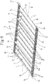
- the conveyor belt 4 further comprises a plurality of cross bars 14.
- Said cross bars 14 extend transversely to said movement direction "M” between the lateral zones 10b (i.e., between the lateral sides 7c).
- the cross bars 14 are orthogonal to the movement direction "M” and parallel to the rotation axes "A", "B" of the first 2 and the second axis 3.
- the presence of cross bars makes it possible to stiffen the conveyor belt 4, allowing the traction body 19 to remain guided within the pulleys 5, 6.
- cross bars 14 are spaced apart along the movement direction "M" by a predetermined (and constant) distance "p".
- this distance "p" is less than or equal to 2/3 ⁇ (d/2), wherein "d” corresponds to the smaller diameter of the first 5 and second pulleys 6, which however is preferably the same.
- At least two cross bars 14 are arranged along the arc of the pulley 5, 6 in contact with the conveyor belt 4.
- the cross bars are placed at a distance "p" comprised between 60 and 130 mm, preferably between 80 and 100 mm. It should also be noted that the cross bars 14 have a transversal extension which is less than or equal to the base body 7, i.e., less than the distance between the two lateral sides 7c.
- the cross bars 14 have a transversal extension at least equal to the distance between the lateral zones 10b.
- the cross bars 14 project (or rise) from the second face 7b of the base body 7, i.e., from the outer face of the conveyor belt 4.
- the plurality of cross bars 14 comprises a plurality of stiffening bars 15 and a plurality of transport bars 16.
- the stiffening bars 15 have a lesser thickness than the transport bars 16, where "thickness", in this case too, indicates the dimension calculated moving away from the second face 7b of the base body 7.
- the thickness of the transport bars 16 is at least twice that of the stiffening bars 15, more preferably about three times the thickness.
- the thickness of the stiffening bars 15 is preferably between 10 and 15mm.
- the thickness of the transport bars 16, on the other hand, is between 30 and 40mm.
- the stiffening bars 15 are greater in number than the transport bars 16.
- the ratio between the number of stiffening bars 15 and the number of transport bars 16 is at least 2, more preferably at least 4.
- the distribution of the cross bars 14 provides one transport bar 16 each four stiffening bars 15, all of which are spaced apart by the distance "p" described above.
- the transport bars 16 have a free end edge 16a (distal from the second face 7b), sawtooth shaped or notched.
- said free end edge 16a has a sawtooth profile; this profile is divided into two half-parts having opposite orientation, moving away from each other.
- the material arriving transversely to the belt is "invited” to surmount the conveyor belt 4 in the first half-part, on the contrary, it is retained on the belt in the second half-part.
- the cross bars 14 are made in one piece with the base body 7, preferably vulcanized thereto.
- the cross bars 14 (at least the stiffening bars 15) comprise a reinforcement core (not shown) embedded in a vulcanized rubber coating on the second face 7b of the base body 7 of the conveyor belt 4.
- the core is therefore made of a material capable of giving transversal stiffness to the bar, for example, a metal material (such as steel, or the like) or, preferably, a composite material such as, for example, glass fibre.
- a metal material such as steel, or the like
- a composite material such as, for example, glass fibre.
- transverse ribs 17a, 17b arranged in longitudinal succession, preferably at a constant distance.
- said ribs comprise first ribs 17a and second ribs 17b alternating with each other along the movement direction "M", wherein each first rib 17a is arranged at a tooth 9 and protrudes from the opposite face of the base body 7.
- Each second rib 17b is interposed between two first ribs 17a, equidistant therefrom.
- the first ribs 17a have a thickness equal to that of the second ribs 17b, but a greater depth (equal to that of the teeth 9).
- the ribs 17a, 17b are less thick than the cross bars 14.
- the ribs are less thick than the cross bars, and more preferably also than the teeth 9.
- the device comprises an idler unit 18 associated with the return section 11b of the conveyor belt 4.
- This idler unit 18 is configured to divert the path of the return section 11b close to the pulleys 5, 6, in order to reduce the distance between the return section 11b and the transport section 11a to a value lower than the diameter of the pulleys 5, 6.
- the idler unit 18 comprises a plurality of rollers/idlers around which the second face 7b of the base body 7 is wound, in particular at the lateral zones 10b.
- rollers/idlers are located at a distance from the transport section 11a smaller than the diameter of the pulleys, so as to reduce the overall dimensions of the conveyor device 1 inside the machinery 100.
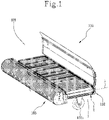
- the conveyor device 1 object of the invention has its preferred (and main) application within a handling and/or unloading system 101 of agricultural machinery 100, area in which the technical advantages related to the invention find their maximum realization.
- the agricultural machinery 100 preferably of the type for harvesting agricultural products, comprises a frame 102 with which the handling and/or unloading system 101 equipped with the conveyor device 1 is associated.
- the frame of the agricultural machinery 100 comprises rolling (or sliding) movement means configured to allow the frame 1 to be driven along a direction of travel.
- Collection means 103 are also provided at the front of the frame 101, which are configured to collect agricultural products from the ground, preferably by means of tines or tongs distributed orthogonally to the direction of travel and rotating continuously.
- the handling and/or unloading system 101 is operatively positioned downstream of the collection means 103 and comprises the conveyor device 1 and a member for actuating the same (not shown).
- the conveyor belt 4 extends horizontally and orthogonally to the direction of travel, substantially along the entire transversal extension of the collection means 103, so as to receive the collected agricultural products and transfer them to a suitable unloading area located near the first 2 or second axis 3.
- the invention achieves the intended objects and attains important advantages.
- cross bars distributed at a suitable distance and having a reinforcement core allows the strength of the belt to be maximized without adversely affecting either the assembly or the weight thereof.
Landscapes
- Engineering & Computer Science (AREA)
- Mechanical Engineering (AREA)
- Life Sciences & Earth Sciences (AREA)
- Environmental Sciences (AREA)
- Belt Conveyors (AREA)
- Structure Of Belt Conveyors (AREA)
- Soil Working Implements (AREA)
- Harvester Elements (AREA)
- Harvesting Machines For Root Crops (AREA)
Priority Applications (1)
| Application Number | Priority Date | Filing Date | Title |
|---|---|---|---|
| SI202130009T SI3920681T1 (sl) | 2020-02-05 | 2021-02-05 | Transportna naprava za kmetijski stroj in kmetijski stroj, ki obsega omenjeno napravo |
Applications Claiming Priority (2)
| Application Number | Priority Date | Filing Date | Title |
|---|---|---|---|
| IT102020000002242A IT202000002242A1 (it) | 2020-02-05 | 2020-02-05 | Dispositivo convogliatore per una macchina agricola e macchina agricola comprendente detto dispositivo |
| PCT/IB2021/050933 WO2021156800A1 (en) | 2020-02-05 | 2021-02-05 | Conveyor device for agricultural machinery and agricultural machinery comprising said device |
Publications (2)
| Publication Number | Publication Date |
|---|---|
| EP3920681A1 EP3920681A1 (en) | 2021-12-15 |
| EP3920681B1 true EP3920681B1 (en) | 2022-07-13 |
Family
ID=70480535
Family Applications (1)
| Application Number | Title | Priority Date | Filing Date |
|---|---|---|---|
| EP21711360.4A Active EP3920681B1 (en) | 2020-02-05 | 2021-02-05 | Conveyor device for agricultural machinery and agricultural machinery comprising said device |
Country Status (9)
| Country | Link |
|---|---|
| US (1) | US12195278B2 (da) |
| EP (1) | EP3920681B1 (da) |
| CA (1) | CA3170112A1 (da) |
| DK (1) | DK3920681T3 (da) |
| ES (1) | ES2928241T3 (da) |
| IT (1) | IT202000002242A1 (da) |
| PL (1) | PL3920681T3 (da) |
| SI (1) | SI3920681T1 (da) |
| WO (1) | WO2021156800A1 (da) |
Families Citing this family (6)
| Publication number | Priority date | Publication date | Assignee | Title |
|---|---|---|---|---|
| DE102021123990B4 (de) * | 2021-09-16 | 2023-04-06 | HHLA Sky GmbH | Landeplattform |
| CN114313792A (zh) * | 2021-12-22 | 2022-04-12 | 昆明泰光机电设备有限公司 | 一种输送带 |
| WO2023168623A1 (zh) * | 2022-03-09 | 2023-09-14 | 深圳市大疆创新科技有限公司 | 无人机基站及无人机系统 |
| US12545447B1 (en) * | 2024-06-07 | 2026-02-10 | Amazon Technologies, Inc. | Aerial vehicle landing pad with sensors |
| US20260048877A1 (en) * | 2024-08-15 | 2026-02-19 | Skydio, Inc. | Base Station For An Unmanned Aerial Vehicle Including A Rotatable Roof Assembly |
| US20260048865A1 (en) * | 2024-08-15 | 2026-02-19 | Skydio, Inc. | Method of docking an unmanned aerial vehicle with a base station |
Family Cites Families (11)
| Publication number | Priority date | Publication date | Assignee | Title |
|---|---|---|---|---|
| US4371580A (en) | 1982-01-26 | 1983-02-01 | Morrison Company, Inc. | Three-ply belting material |
| US4553663A (en) * | 1984-05-10 | 1985-11-19 | The Goodyear Tire & Rubber Company | Conveyor for a crop harvester |
| US6935488B2 (en) * | 2003-03-31 | 2005-08-30 | Oxbo International Corporation | Blade pulley |
| WO2007090149A2 (en) * | 2006-01-31 | 2007-08-09 | Thermodrive Llc | Low friction, direct drive pin conveyor belt |
| WO2007092776A2 (en) * | 2006-02-02 | 2007-08-16 | Thermodrive Llc | Conveyor with multiple belts driven by a single shaft |
| CA2564777C (en) | 2006-10-20 | 2010-08-03 | Macdon Industries Ltd. | Crop header with draper canvas and a seal with an element of the cutter bar |
| DE102009036104B4 (de) * | 2009-07-27 | 2012-02-09 | Artemis Kautschuk- Und Kunststoff-Technik Gmbh | Schrägförderer für Mähdrescher |
| DE102010004799A1 (de) * | 2010-01-16 | 2011-07-21 | ARTEMIS Kautschuk- und Kunststoff-Technik GmbH, 30559 | Förderband für Landmaschinen, insbesondere für Schwader |
| ITRN20130031A1 (it) * | 2013-08-08 | 2015-02-09 | Roc S R L | Organo rotante per la pulizia di dispositivi di raccolta per prodotti agricoli di forma esile e longilinea, dispositivo di raccolta comprendente detto organo e metodo di perfezionamento di tale dispositivo di raccolta. |
| DE102015118143A1 (de) * | 2015-10-23 | 2017-04-27 | Arnold Jäger Holding GmbH | Nockenriemen, insbesondere für landwirtschaftliche Maschinen |
| EP3278656A1 (en) * | 2016-08-01 | 2018-02-07 | I.G. S.R.L. | Rake assembly |
-
2020
- 2020-02-05 IT IT102020000002242A patent/IT202000002242A1/it unknown
-
2021
- 2021-02-05 US US17/797,420 patent/US12195278B2/en active Active
- 2021-02-05 SI SI202130009T patent/SI3920681T1/sl unknown
- 2021-02-05 PL PL21711360.4T patent/PL3920681T3/pl unknown
- 2021-02-05 EP EP21711360.4A patent/EP3920681B1/en active Active
- 2021-02-05 CA CA3170112A patent/CA3170112A1/en active Pending
- 2021-02-05 WO PCT/IB2021/050933 patent/WO2021156800A1/en not_active Ceased
- 2021-02-05 DK DK21711360.4T patent/DK3920681T3/da active
- 2021-02-05 ES ES21711360T patent/ES2928241T3/es active Active
Also Published As
| Publication number | Publication date |
|---|---|
| IT202000002242A1 (it) | 2021-08-05 |
| EP3920681A1 (en) | 2021-12-15 |
| US20230096139A1 (en) | 2023-03-30 |
| DK3920681T3 (da) | 2022-10-24 |
| WO2021156800A1 (en) | 2021-08-12 |
| SI3920681T1 (sl) | 2022-11-30 |
| CA3170112A1 (en) | 2021-08-12 |
| PL3920681T3 (pl) | 2022-11-21 |
| ES2928241T3 (es) | 2022-11-16 |
| US12195278B2 (en) | 2025-01-14 |
Similar Documents
| Publication | Publication Date | Title |
|---|---|---|
| EP3920681B1 (en) | Conveyor device for agricultural machinery and agricultural machinery comprising said device | |
| EP2200913B1 (en) | Flat wire conveyor belt system | |
| US8561790B2 (en) | Belt drive conveyor with power tap off | |
| US7832549B2 (en) | Curved conveyor with guide for preventing radial belt migration | |
| AU2013334571B2 (en) | Positively-driven, low tension transfer conveyor | |
| EA025671B1 (ru) | Конвейерная установка и опорное устройство | |
| JP2013126920A (ja) | トラフ形の低摩擦ポジティブドライブベルトを備えるコンベヤ | |
| EP1060111B1 (en) | Curved conveyor | |
| US5176248A (en) | Belted chain | |
| SE456736B (sv) | Anordning vid bandtransportoerer | |
| US8997974B2 (en) | Transversely deformable endless conveyor belt for a conveyor device | |
| US6484871B2 (en) | Segmented belt turn conveyor belt | |
| RU2258658C1 (ru) | Конвейер с подвесной лентой | |
| WO2007090149A2 (en) | Low friction, direct drive pin conveyor belt | |
| US11926479B2 (en) | Rod belt for agricultural machines | |
| US20030234162A1 (en) | Boost drive for a modular plastic conveyor belt | |
| GB2371280A (en) | Drive assembly | |
| MXPA00006829A (en) | Curved conveyor |
Legal Events
| Date | Code | Title | Description |
|---|---|---|---|
| STAA | Information on the status of an ep patent application or granted ep patent |
Free format text: STATUS: UNKNOWN |
|
| STAA | Information on the status of an ep patent application or granted ep patent |
Free format text: STATUS: THE INTERNATIONAL PUBLICATION HAS BEEN MADE |
|
| PUAI | Public reference made under article 153(3) epc to a published international application that has entered the european phase |
Free format text: ORIGINAL CODE: 0009012 |
|
| STAA | Information on the status of an ep patent application or granted ep patent |
Free format text: STATUS: REQUEST FOR EXAMINATION WAS MADE |
|
| 17P | Request for examination filed |
Effective date: 20210909 |
|
| AK | Designated contracting states |
Kind code of ref document: A1 Designated state(s): AL AT BE BG CH CY CZ DE DK EE ES FI FR GB GR HR HU IE IS IT LI LT LU LV MC MK MT NL NO PL PT RO RS SE SI SK SM TR |
|
| GRAP | Despatch of communication of intention to grant a patent |
Free format text: ORIGINAL CODE: EPIDOSNIGR1 |
|
| STAA | Information on the status of an ep patent application or granted ep patent |
Free format text: STATUS: GRANT OF PATENT IS INTENDED |
|
| DAV | Request for validation of the european patent (deleted) | ||
| DAX | Request for extension of the european patent (deleted) | ||
| INTG | Intention to grant announced |
Effective date: 20220209 |
|
| RAP3 | Party data changed (applicant data changed or rights of an application transferred) |
Owner name: ROC S.R.L |
|
| GRAS | Grant fee paid |
Free format text: ORIGINAL CODE: EPIDOSNIGR3 |
|
| GRAA | (expected) grant |
Free format text: ORIGINAL CODE: 0009210 |
|
| STAA | Information on the status of an ep patent application or granted ep patent |
Free format text: STATUS: THE PATENT HAS BEEN GRANTED |
|
| AK | Designated contracting states |
Kind code of ref document: B1 Designated state(s): AL AT BE BG CH CY CZ DE DK EE ES FI FR GB GR HR HU IE IS IT LI LT LU LV MC MK MT NL NO PL PT RO RS SE SI SK SM TR |
|
| REG | Reference to a national code |
Ref country code: CH Ref legal event code: EP |
|
| REG | Reference to a national code |
Ref country code: DE Ref legal event code: R096 Ref document number: 602021000210 Country of ref document: DE |
|
| REG | Reference to a national code |
Ref country code: AT Ref legal event code: REF Ref document number: 1503815 Country of ref document: AT Kind code of ref document: T Effective date: 20220815 |
|
| REG | Reference to a national code |
Ref country code: IE Ref legal event code: FG4D |
|
| REG | Reference to a national code |
Ref country code: FI Ref legal event code: FGE |
|
| REG | Reference to a national code |
Ref country code: DK Ref legal event code: T3 Effective date: 20221018 |
|
| REG | Reference to a national code |
Ref country code: NL Ref legal event code: FP |
|
| REG | Reference to a national code |
Ref country code: LT Ref legal event code: MG9D |
|
| REG | Reference to a national code |
Ref country code: ES Ref legal event code: FG2A Ref document number: 2928241 Country of ref document: ES Kind code of ref document: T3 Effective date: 20221116 |
|
| PG25 | Lapsed in a contracting state [announced via postgrant information from national office to epo] |
Ref country code: SE Free format text: LAPSE BECAUSE OF FAILURE TO SUBMIT A TRANSLATION OF THE DESCRIPTION OR TO PAY THE FEE WITHIN THE PRESCRIBED TIME-LIMIT Effective date: 20220713 Ref country code: RS Free format text: LAPSE BECAUSE OF FAILURE TO SUBMIT A TRANSLATION OF THE DESCRIPTION OR TO PAY THE FEE WITHIN THE PRESCRIBED TIME-LIMIT Effective date: 20220713 Ref country code: PT Free format text: LAPSE BECAUSE OF FAILURE TO SUBMIT A TRANSLATION OF THE DESCRIPTION OR TO PAY THE FEE WITHIN THE PRESCRIBED TIME-LIMIT Effective date: 20221114 Ref country code: NO Free format text: LAPSE BECAUSE OF FAILURE TO SUBMIT A TRANSLATION OF THE DESCRIPTION OR TO PAY THE FEE WITHIN THE PRESCRIBED TIME-LIMIT Effective date: 20221013 Ref country code: LV Free format text: LAPSE BECAUSE OF FAILURE TO SUBMIT A TRANSLATION OF THE DESCRIPTION OR TO PAY THE FEE WITHIN THE PRESCRIBED TIME-LIMIT Effective date: 20220713 Ref country code: LT Free format text: LAPSE BECAUSE OF FAILURE TO SUBMIT A TRANSLATION OF THE DESCRIPTION OR TO PAY THE FEE WITHIN THE PRESCRIBED TIME-LIMIT Effective date: 20220713 |
|
| PG25 | Lapsed in a contracting state [announced via postgrant information from national office to epo] |
Ref country code: IS Free format text: LAPSE BECAUSE OF FAILURE TO SUBMIT A TRANSLATION OF THE DESCRIPTION OR TO PAY THE FEE WITHIN THE PRESCRIBED TIME-LIMIT Effective date: 20221113 Ref country code: HR Free format text: LAPSE BECAUSE OF FAILURE TO SUBMIT A TRANSLATION OF THE DESCRIPTION OR TO PAY THE FEE WITHIN THE PRESCRIBED TIME-LIMIT Effective date: 20220713 Ref country code: GR Free format text: LAPSE BECAUSE OF FAILURE TO SUBMIT A TRANSLATION OF THE DESCRIPTION OR TO PAY THE FEE WITHIN THE PRESCRIBED TIME-LIMIT Effective date: 20221014 |
|
| REG | Reference to a national code |
Ref country code: DE Ref legal event code: R097 Ref document number: 602021000210 Country of ref document: DE |
|
| PG25 | Lapsed in a contracting state [announced via postgrant information from national office to epo] |
Ref country code: SM Free format text: LAPSE BECAUSE OF FAILURE TO SUBMIT A TRANSLATION OF THE DESCRIPTION OR TO PAY THE FEE WITHIN THE PRESCRIBED TIME-LIMIT Effective date: 20220713 Ref country code: RO Free format text: LAPSE BECAUSE OF FAILURE TO SUBMIT A TRANSLATION OF THE DESCRIPTION OR TO PAY THE FEE WITHIN THE PRESCRIBED TIME-LIMIT Effective date: 20220713 |
|
| PLBE | No opposition filed within time limit |
Free format text: ORIGINAL CODE: 0009261 |
|
| STAA | Information on the status of an ep patent application or granted ep patent |
Free format text: STATUS: NO OPPOSITION FILED WITHIN TIME LIMIT |
|
| PG25 | Lapsed in a contracting state [announced via postgrant information from national office to epo] |
Ref country code: SK Free format text: LAPSE BECAUSE OF FAILURE TO SUBMIT A TRANSLATION OF THE DESCRIPTION OR TO PAY THE FEE WITHIN THE PRESCRIBED TIME-LIMIT Effective date: 20220713 Ref country code: EE Free format text: LAPSE BECAUSE OF FAILURE TO SUBMIT A TRANSLATION OF THE DESCRIPTION OR TO PAY THE FEE WITHIN THE PRESCRIBED TIME-LIMIT Effective date: 20220713 |
|
| 26N | No opposition filed |
Effective date: 20230414 |
|
| PG25 | Lapsed in a contracting state [announced via postgrant information from national office to epo] |
Ref country code: AL Free format text: LAPSE BECAUSE OF FAILURE TO SUBMIT A TRANSLATION OF THE DESCRIPTION OR TO PAY THE FEE WITHIN THE PRESCRIBED TIME-LIMIT Effective date: 20220713 |
|
| P01 | Opt-out of the competence of the unified patent court (upc) registered |
Effective date: 20230525 |
|
| REG | Reference to a national code |
Ref country code: AT Ref legal event code: UEP Ref document number: 1503815 Country of ref document: AT Kind code of ref document: T Effective date: 20220713 |
|
| PG25 | Lapsed in a contracting state [announced via postgrant information from national office to epo] |
Ref country code: MC Free format text: LAPSE BECAUSE OF FAILURE TO SUBMIT A TRANSLATION OF THE DESCRIPTION OR TO PAY THE FEE WITHIN THE PRESCRIBED TIME-LIMIT Effective date: 20220713 |
|
| REG | Reference to a national code |
Ref country code: BE Ref legal event code: MM Effective date: 20230228 |
|
| PG25 | Lapsed in a contracting state [announced via postgrant information from national office to epo] |
Ref country code: LU Free format text: LAPSE BECAUSE OF NON-PAYMENT OF DUE FEES Effective date: 20230205 |
|
| REG | Reference to a national code |
Ref country code: IE Ref legal event code: MM4A |
|
| PG25 | Lapsed in a contracting state [announced via postgrant information from national office to epo] |
Ref country code: IE Free format text: LAPSE BECAUSE OF NON-PAYMENT OF DUE FEES Effective date: 20230205 |
|
| PG25 | Lapsed in a contracting state [announced via postgrant information from national office to epo] |
Ref country code: BE Free format text: LAPSE BECAUSE OF NON-PAYMENT OF DUE FEES Effective date: 20230228 |
|
| PG25 | Lapsed in a contracting state [announced via postgrant information from national office to epo] |
Ref country code: BG Free format text: LAPSE BECAUSE OF FAILURE TO SUBMIT A TRANSLATION OF THE DESCRIPTION OR TO PAY THE FEE WITHIN THE PRESCRIBED TIME-LIMIT Effective date: 20220713 |
|
| PG25 | Lapsed in a contracting state [announced via postgrant information from national office to epo] |
Ref country code: BG Free format text: LAPSE BECAUSE OF FAILURE TO SUBMIT A TRANSLATION OF THE DESCRIPTION OR TO PAY THE FEE WITHIN THE PRESCRIBED TIME-LIMIT Effective date: 20220713 |
|
| PGFP | Annual fee paid to national office [announced via postgrant information from national office to epo] |
Ref country code: SI Payment date: 20250123 Year of fee payment: 5 |
|
| PGFP | Annual fee paid to national office [announced via postgrant information from national office to epo] |
Ref country code: ES Payment date: 20250331 Year of fee payment: 5 |
|
| PG25 | Lapsed in a contracting state [announced via postgrant information from national office to epo] |
Ref country code: CY Free format text: LAPSE BECAUSE OF FAILURE TO SUBMIT A TRANSLATION OF THE DESCRIPTION OR TO PAY THE FEE WITHIN THE PRESCRIBED TIME-LIMIT; INVALID AB INITIO Effective date: 20210205 |
|
| PG25 | Lapsed in a contracting state [announced via postgrant information from national office to epo] |
Ref country code: HU Free format text: LAPSE BECAUSE OF FAILURE TO SUBMIT A TRANSLATION OF THE DESCRIPTION OR TO PAY THE FEE WITHIN THE PRESCRIBED TIME-LIMIT; INVALID AB INITIO Effective date: 20210205 |
|
| PG25 | Lapsed in a contracting state [announced via postgrant information from national office to epo] |
Ref country code: TR Free format text: LAPSE BECAUSE OF FAILURE TO SUBMIT A TRANSLATION OF THE DESCRIPTION OR TO PAY THE FEE WITHIN THE PRESCRIBED TIME-LIMIT Effective date: 20220713 |
|
| REG | Reference to a national code |
Ref country code: CH Ref legal event code: U11 Free format text: ST27 STATUS EVENT CODE: U-0-0-U10-U11 (AS PROVIDED BY THE NATIONAL OFFICE) Effective date: 20260301 |
|
| PGFP | Annual fee paid to national office [announced via postgrant information from national office to epo] |
Ref country code: NL Payment date: 20260218 Year of fee payment: 6 |
|
| PGFP | Annual fee paid to national office [announced via postgrant information from national office to epo] |
Ref country code: GB Payment date: 20260220 Year of fee payment: 6 |
|
| PGFP | Annual fee paid to national office [announced via postgrant information from national office to epo] |
Ref country code: DK Payment date: 20260220 Year of fee payment: 6 Ref country code: DE Payment date: 20260218 Year of fee payment: 6 |
|
| PGFP | Annual fee paid to national office [announced via postgrant information from national office to epo] |
Ref country code: AT Payment date: 20260219 Year of fee payment: 6 |
|
| PGFP | Annual fee paid to national office [announced via postgrant information from national office to epo] |
Ref country code: FI Payment date: 20260226 Year of fee payment: 6 Ref country code: IT Payment date: 20260224 Year of fee payment: 6 |
|
| PGFP | Annual fee paid to national office [announced via postgrant information from national office to epo] |
Ref country code: FR Payment date: 20260219 Year of fee payment: 6 |
|
| PGFP | Annual fee paid to national office [announced via postgrant information from national office to epo] |
Ref country code: CZ Payment date: 20260127 Year of fee payment: 6 Ref country code: CH Payment date: 20260301 Year of fee payment: 6 |
|
| PGFP | Annual fee paid to national office [announced via postgrant information from national office to epo] |
Ref country code: PL Payment date: 20260123 Year of fee payment: 6 |