EP3922075B1 - Partage de temps d'occupation de canal (cot) initié par un équipement utilisateur entre de multiples équipements utilisateurs - Google Patents
Partage de temps d'occupation de canal (cot) initié par un équipement utilisateur entre de multiples équipements utilisateurs Download PDFInfo
- Publication number
- EP3922075B1 EP3922075B1 EP19827854.1A EP19827854A EP3922075B1 EP 3922075 B1 EP3922075 B1 EP 3922075B1 EP 19827854 A EP19827854 A EP 19827854A EP 3922075 B1 EP3922075 B1 EP 3922075B1
- Authority
- EP
- European Patent Office
- Prior art keywords
- cot
- information
- wireless devices
- wireless device
- shared
- Prior art date
- Legal status (The legal status is an assumption and is not a legal conclusion. Google has not performed a legal analysis and makes no representation as to the accuracy of the status listed.)
- Active
Links
Images







Classifications
-
- H—ELECTRICITY
- H04—ELECTRIC COMMUNICATION TECHNIQUE
- H04W—WIRELESS COMMUNICATION NETWORKS
- H04W74/00—Wireless channel access
- H04W74/08—Non-scheduled access, e.g. ALOHA
-
- H—ELECTRICITY
- H04—ELECTRIC COMMUNICATION TECHNIQUE
- H04W—WIRELESS COMMUNICATION NETWORKS
- H04W74/00—Wireless channel access
- H04W74/08—Non-scheduled access, e.g. ALOHA
- H04W74/0808—Non-scheduled access, e.g. ALOHA using carrier sensing, e.g. carrier sense multiple access [CSMA]
-
- H—ELECTRICITY
- H04—ELECTRIC COMMUNICATION TECHNIQUE
- H04W—WIRELESS COMMUNICATION NETWORKS
- H04W16/00—Network planning, e.g. coverage or traffic planning tools; Network deployment, e.g. resource partitioning or cells structures
- H04W16/14—Spectrum sharing arrangements between different networks
-
- H—ELECTRICITY
- H04—ELECTRIC COMMUNICATION TECHNIQUE
- H04W—WIRELESS COMMUNICATION NETWORKS
- H04W76/00—Connection management
- H04W76/20—Manipulation of established connections
- H04W76/28—Discontinuous transmission [DTX]; Discontinuous reception [DRX]
Definitions
- the present disclosure relates to a wireless system operating in unlicensed spectrum and more specifically relates to Channel Occupancy Time (COT) sharing in a wireless system operating in unlicensed spectrum.
- COT Channel Occupancy Time
- Next generation systems are expected to support a wide range of use cases with varying requirements ranging from fully mobile devices to stationary Internet of Things (IoT) or fixed wireless broadband devices.
- the traffic pattern associated with many use cases is expected to consist of short or long bursts of data traffic with varying lengths of waiting periods in between, where a User Equipment (UE) is said to be in an "inactive state" during these waiting periods.
- 3GPP Third Generation Partnership Project
- NR New Radio
- LAA License Assisted Access
- LAA License Assisted Access
- LAA License Assisted Access
- LAA License Assisted Access
- LAA License Assisted Access
- LAA License Assisted Access
- LAA License Assisted Access
- LAA License Assisted Access
- LAA License Assisted Access
- SR Scheduling Request
- NR is considered for both licensed and unlicensed spectrum.
- 3GPP has defined a study item on NR-based Access to Unlicensed Spectrum, which was approved at RAN-77.
- LTE Long Term Evolution
- NR-U also needs to support Dual-Connectivity (DC) and standalone scenarios, where the Medium Access Control (MAC) procedures including the Random Access Channel (RACH) procedure and scheduling procedure on unlicensed spectrum are subject to LBT failures.
- MAC Medium Access Control
- RACH Random Access Channel
- DRS Discovery Reference Signal
- PSS Primary Synchronization Signal
- SSS Secondary Synchronization Signal
- PBCH Physical Broadcast Channel
- CSI-RS Channel State Information Reference Signal
- control channel transmission such as Physical Uplink Control Channel (PUCCH) / Physical Downlink Control Channel (PDCCH), physical data channel such as Physical Uplink Shared Channel (PUSCH) / Physical Downlink Shared Channel (PDSCH), and uplink sounding reference signal such as Sounding Reference Signal (SRS) transmission
- PUCCH Physical Uplink Control Channel
- PDCCH Physical Downlink Control Channel
- PUSCH Physical Uplink Shared Channel
- PDSCH Physical Downlink Shared Channel
- SRS Sounding Reference Signal
- RRM Radio Resource Management
- eLAA enhanced LAA
- feLAA further enhanced LAA
- RRM measurements and reporting will include a special configuration procedure(s) with respect to the channel sensing and channel availability.
- LAA channel access/selection for LAA was one of the important aspects for co-existence with other RATs, such as WiFi.
- LAA has aimed to use carriers that are congested with WiFi.
- the UE measures Reference Signal Received Power (RSRP) and Reference Signal Received Quality (RSRQ) of the downlink radio channel, and provides the measurement reports to its serving enhanced or evolved Node B (eNB) in LTE or to its serving Next Generation Node B (gNB) in NR.
- RSRP Reference Signal Received Power
- RSRQ Reference Signal Received Quality
- eNB enhanced or evolved Node B
- gNB Next Generation Node B
- RSSI Received Signal Strength Indicator
- RSSI Received Signal Strength Indicator
- the measurements in terms of RSSI are very useful.
- the RSSI measurements together with the time information concerning when and how long that UEs have made the measurements can assist the gNB/eNB to detect a hidden node. Additionally, the gNB/eNB can measure the load situation of the carrier which is useful for the network to prioritize some channels for load balance and channel access failure avoidance purposes.
- LTE LAA has been defined to support measurements of averaged RSSI and channel occupancy for measurement reports.
- the channel occupancy is defined as percentage of time that RSSI was measured above a configured threshold.
- an RSSI Measurement Timing Configuration includes a measurement duration (e.g., 1-5 milliseconds (ms)) and a period between measurements (e.g., ⁇ 40, 80, 160, 320, 640 ⁇ ms).
- LBT is designed for unlicensed spectrum co-existence with other RATs.
- a radio device applies a Clear Channel Assessment (CCA) check (i.e., channel sensing) before any transmission.
- CCA Clear Channel Assessment
- the transmitter uses Energy Detection (ED) over a time period compared to a certain threshold (ED threshold) to determine if a channel is idle. In case the channel is determined to be occupied, the transmitter performs a random back-off within a contention window before next CCA attempt.
- ACK Acknowledgement
- the transmitter must defer a period after each busy CCA slot prior to resuming back-off.
- MCOT Maximum Channel Occupancy Time
- QoS Quality of Service
- CWSs Contention Window Sizes
- MCOT MCOT between services
- the SR is used for requesting Uplink Shared Channel (UL-SCH) resources for a new transmission.
- the MAC entity may be configured with zero, one, or more SR configurations.
- An SR configuration consists of a set of PUCCH resources for SR transmission across different Bandwidth Parts (BWPs) and cells. For a logical channel, at most one PUCCH resource for SR is configured per BWP.
- BWPs Bandwidth Parts
- Each SR configuration corresponds to one or more Logical Channels (LCHs).
- LCH Logical Channels
- Each LCH may be mapped to zero or one SR configuration, which is configured by Radio Resource Control (RRC).
- RRC Radio Resource Control
- BSR Buffer Status Report
- the corresponding SR configuration for the triggered SR is that of the highest priority LCH, if such a configuration exists, that has data available for transmission at the time the BSR is triggered.
- a typical scheduling procedure is illustrated in Figure 1 .
- the UE or the gNB has to perform a channel sensing or LBT prior to any transmission in this procedure.
- new data arrives at the UE for transmission, and a BSR and SR is triggered.
- the UE sends the SR to the gNB.
- the gNB typically sends a small uplink grant to the UE to let the UE transmit the BSR.
- the UE uses the grant, the UE transmits the BSR and possibly additional data.
- the gNB may provide a second uplink grant for the rest of the data.
- COT Channel Occupancy Time
- a node e.g., NR-U gNB/UE, LTE-LAA eNB/UE, or WiFi Access Point (AP) / Station (STA)
- AP WiFi Access Point
- STA Station
- This procedure typically includes sensing the medium to be idle for a number of time intervals. Sensing the medium to be idle can be done in different ways, e.g. using energy detection, preamble detection, or using virtual carrier sensing. The latter implies that the node reads control information from other transmitting nodes informing when a transmission ends.
- TXOP Transmission Opportunity
- the length of the TXOP depends on regulation and type of CCA that has been performed, but typically ranges from 1 ms to 10 ms. This duration is often referred to as a COT.
- SIFS Short Interframe Spacing
- aSIFSTime aRxPHYDelay + aMACProcessingDelay + aRxTxTurnaroundTime
- Figure 2 illustrates TXOPs both with and without COT sharing where CCA is performed by the initiating node (gNB).
- CCA is performed by the initiating node (gNB).
- the gap between downlink and uplink transmission is less than 16 ⁇ s.
- 3GPP contribution R1-1900789 discloses that the COT sharing information may be conveyed to the gNB within UCI.
- Radio Node As used herein, a "radio node” is either a radio access node or a wireless device.
- Radio Access Node As used herein, a "radio access node” or “radio network node” is any node in a radio access network of a cellular communications network that operates to wirelessly transmit and/or receive signals.
- a radio access node include, but are not limited to, a base station (e.g., a next generation base station (gNB) in a Third Generation Partnership Project (3GPP) Fifth Generation (5G) New Radio (NR) network or an enhanced or evolved Node B (eNB) in a 3GPP Long Term Evolution (LTE) network), a high-power or macro base station, a low-power base station (e.g., a micro base station, a pico base station, a home eNB, or the like), and a relay node.
- a base station e.g., a next generation base station (gNB) in a Third Generation Partnership Project (3GPP) Fifth Generation (5G) New Radio (NR) network or an enhanced or evolved Node B (eNB) in a
- a "core network node” is any type of node in a core network.
- Some examples of a core network node include, e.g., a Mobility Management Entity (MME), a Packet Data Network Gateway (P-GW), a Service Capability Exposure Function (SCEF), or the like.
- MME Mobility Management Entity
- P-GW Packet Data Network Gateway
- SCEF Service Capability Exposure Function
- a “wireless device” is any type of device that has access to (i.e., is served by) a cellular communications network by wirelessly transmitting and/or receiving signals to a radio access node(s).
- a wireless device include, but are not limited to, a User Equipment (UE) in a 3GPP network and a Machine Type Communication (MTC) device.
- UE User Equipment
- MTC Machine Type Communication
- an uplink burst for a UE consisting of one or more of Physical Uplink Shared Channel (PUSCH), Physical Uplink Control Channel (PUCCH), Physical Random Access Channel (PRACH), and Sounding Reference Signal (SRS) follows the channel access schemes in Table 7.2.1.3.1-3, which is reproduced below.
- PUSCH Physical Uplink Shared Channel
- PUCCH Physical Uplink Control Channel
- PRACH Physical Random Access Channel
- SRS Sounding Reference Signal
- Table 7.2.1.3.1-3 Channel access schemes for a UL burst within a gNB-initiated COT as LBE device Cat 1 Immediate transmission Cat 2 LBT Cat 4 LBT When the gap from the end of the DL transmission to the beginning of the UL burst is not more than 16 ⁇ sec. Note: Maximum limits of the duration of the UL burst other than those already derived from MCOT duration limits should be further discussed when specifications are developed.
- N/A When the gap between any two successive scheduled/granted transmissions in the COT is not greater than 25 ⁇ sec •
- An UL burst is defined as a set of transmissions from a given UE having no gaps or gaps of no more than 16 ⁇ s. Transmissions from a UE having a gap of more than 16 ⁇ s are considered as separate UL bursts.
- the number of LBT attempts within a COT should be determined when specifications are developed.
- NR Unlicensed NR-U
- LBT Listen-Before-Talk
- RAN1 It has been proposed in RAN1 (see, e.g., R1-1900996) to use Group Common Physical Downlink Control Channel (PDCCH) (GC-PDCCH) with a potential update to indicate both a downlink burst and the COT structure (e.g., the COT duration and/or the end-of-COT).
- PDCCH Group Common Physical Downlink Control Channel
- GC-PDCCH Group Common Physical Downlink Control Channel
- this information may be used by a UE to control when the UE switches from performing Cat2 LBT (within a shared COT) to CAT4 LBT (outside the COT).
- the base station decides which UEs are to share the UE initiated COT.
- COT information related to the shared COT is signaled to UEs (e.g., all UEs) in the cell/carrier/BWP/channel/subband.
- UEs e.g., all UEs
- the UEs that are assigned to the shared COT can organize transmissions based on grants assigned by the base station (e.g., gNB).
- a Discontinuous Reception (DRX) configuration of a UE and/or PDCCH monitoring of the UE are adapted (e.g., by the UE) based on the received COT information signaling. For example, a UE that is not assigned to a COT can switch to a DRX configuration with less often/shorter activation periods such that energy consumption is reduced.
- DRX Discontinuous Reception
- Certain embodiments may provide one or more of the following technical advantage(s). With proposed mechanisms:
- Figure 3 illustrates one example of a cellular communications network 300 in which embodiments of the present disclosure may be implemented.
- the cellular communications network 300 is a 5G NR network or NR-U network; however the present disclosure is not limited thereto.
- the cellular communications network 300 includes base stations 302-1 and 302-2, which in 5G NR are referred to as gNBs, controlling corresponding macro cells 304-1 and 304-2.
- the base stations 302-1 and 302-2 are generally referred to herein collectively as base stations 302 and individually as base station 302.
- the macro cells 304-1 and 304-2 are generally referred to herein collectively as macro cells 304 and individually as macro cell 304.
- the cellular communications network 300 may also include a number of low power nodes 306-1 through 306-4 controlling corresponding small cells 308-1 through 308-4.
- the low power nodes 306-1 through 306-4 can be small base stations (such as pico or femto base stations) or Remote Radio Heads (RRHs), or the like.
- RRHs Remote Radio Heads
- one or more of the small cells 308-1 through 308-4 may alternatively be provided by the base stations 302.
- the low power nodes 306-1 through 306-4 are generally referred to herein collectively as low power nodes 306 and individually as low power node 306.
- the small cells 308-1 through 308-4 are generally referred to herein collectively as small cells 308 and individually as small cell 308.
- the base stations 302 (and optionally the low power nodes 306) are connected to a core network 310.
- the base stations 302 and the low power nodes 306 provide service to wireless devices 312-1 through 312-5 in the corresponding cells 304 and 308.
- the wireless devices 312-1 through 312-5 are generally referred to herein collectively as wireless devices 312 and individually as wireless device 312.
- the wireless devices 312 are also sometimes referred to herein as UEs.
- At least some of the cells 304 and/or at least some of the cells 308 are NR-U cells (i.e., NR cells operating in unlicensed spectrum).
- LAA License Assisted Access
- eLAA enhanced LAA
- feLAA further enhanced LAA
- NR-U uses configurable LBT schemes, which comprise at least one of the LBT categories listed below (also referred to as Type 1 or Type 2 channel access in the 3GPP specifications, e.g., Technical Specification (TS) 36.213-f00), but not limited to below examples;
- LBT categories listed below also referred to as Type 1 or Type 2 channel access in the 3GPP specifications, e.g., Technical Specification (TS) 36.213-f00
- TS Technical Specification
- Category 4 LBT in order to provide differentiation to channel access priorities based on the type of traffic served (e.g., Voice over Internet Protocol (VoIP), video, best effort, or background), four LBT priority classes are defined with different Contention Window Sizes (CWSs) and Maximum Channel Occupancy Times (MCOTs). Note that after the transmitter has gained access to the channel, the transmitter is only allowed to transmit for a limited duration, referred to as the MCOT.
- Table 1 summarizes the MCOT and CWS for the downlink channel access priority classes, while Table 2 summarizes the MCOT and CWS for the uplink channel access priority classes. Both tables are abstracted from the Table 15.1.1-1 and the Table 15.2.1-1 in 3GPP TS 36.213 V15.1.0.
- COT structure information (also referred to herein as "COT information") is signaled by the gNB in the respective cell, carrier, BWP, channel, or subband.
- COT structure information may contain/indicate information such as any combination of one or more of the following information:
- DRS Reference Signal
- a shared COT is initiated by at least one transmitting UE via at least one of below alternatives:
- the UEs that are assigned to the shared COT are scheduled based on an improved scheduling strategy, such that the scheduling decision for UEs in the shared COT may be valid for the whole COT period. In other words, the other UEs will not be scheduled during this COT period. While in an ordinary scheduling procedure, a scheduling decision for a UE is typically valid for just one scheduling period (e.g., Transmission Time Interval (TTI) or slot). For each COT based scheduling occasion, the UEs in the cell may be requested by the gNB to transmit SRS and PHR before a COT scheduling decision is made.
- TTI Transmission Time Interval
- the UEs then adapt their PDCCH monitoring to increase PDCCH monitoring. For example, those UEs may switch from a first PDCCH monitoring pattern (e.g., an infrequent PDCCH monitoring pattern) to second PDCCH monitoring pattern (e.g., a more frequent PDCCH monitoring pattern) that results in increased PDCCH monitoring.
- a grant either a dynamic grant or a configured grant
- the UE prepares a Medium Access Control (MAC) Protocol Data Unit (PDU) and triggers a transmission accordingly.
- MAC Medium Access Control
- PDU Protocol Data Unit
- both the gNB and the UEs joining the shared COT period schedule or organize transmissions within the shared COT considering the following aspects:
- UEs that are not assigned to the shared COT by the gNB wait to be scheduled after the current on-going shared COT.
- these UEs can switch to an infrequent PDCCH monitoring pattern until the current COT period has expired, e.g., for power saving purposes. After expiration of the current on-going COT, these UEs can switch to a more frequent PDCCH monitoring pattern to prepare for reception of downlink signaling related to the next COT, which may be intended to them. If those UEs are again not assigned to the next shared COT, the UEs can switch back to an infrequent PDCCH monitoring pattern again.
- the UEs are assigned to the next shared COT, then those UEs continue using the more frequent PDCCH monitoring pattern or may even switch to an even more frequent PDCCH monitoring pattern to prepare for the data transmission.
- For each COT there may be a gap period at the beginning or at the end of the COT period, where the gap is reserved for UEs to transmit SR, BSR, and/or UCI to request resources, and/or for the gNB to transmit downlink signaling such as a Downlink Control Information (DCI) signaling to start a new COT (either for downlink transmission or a uplink shared COT for multiple UEs).
- DCI Downlink Control Information
- the COT information for sharing between multiple UEs may be signaled by a gNB via any one of the following example alternatives:
- the COT information is preferably signaled in the cell, carrier, BWP, channel, or subband such that all UEs can read the signaling to determine whether there is a shared COT scheduled in the cell, carrier, BWP, channel, subband, or group.
- the gNB signals each UE to indicate to the UE whether the UE is assigned to the shared COT.
- the COT information includes information that indicates the UEs that are assigned to the shared COT (e.g., the COT information signaling includes the UE IDs of the UEs assigned to the shared COT).
- each UE decides if it is assigned to the shared COT via a second signaling.
- the second signaling may be a dedicated DCI.
- a UE first detects if there is a shared COT indicated by the gNB via the COT information. After that, the UE can further decide if it is assigned to the shared COT via the reception of a second signaling (e.g., reception of DCI including an uplink grant for the UE during the shared COT).
- a second signaling e.g., reception of DCI including an uplink grant for the UE during the shared COT.
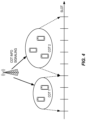
- FIG. 4 illustrates one example of COT sharing.
- a first COT (COT1) is shared by two UEs and spans three slots in time
- a second COT (COT2) is shared by three other UEs and spans five slots in time.
- each COT period may comprise a gap period at the beginning of the COT or the end of the COT, where this gap allows for the gNB or some UEs to perform LBT operation for any potential downlink or uplink signaling.
- a UE adapts its DRX activity (also referred to herein as its DRX configuration) based on received COT signaling.
- a UE applies a first DRX configuration (e.g., a DRX configuration with less often and/or shorter active periods) during the time periods when the UE is not assigned to a shared COT, while the UE applies a second DRX configuration (e.g., a DRX configuration with more often and/or longer active periods) during the time periods when the UE is assigned to a shared COT.
- reception of a COT assignment signaling would trigger the UE to switch or adapt its DRX configuration.
- the DRX configuration is reconfigured for a UE every time with an RRC reconfiguration message.
- multiple DRX configurations are pre-configured for the UE, and the UE chooses a suitable DRX configuration depending on whether the UE is assigned to a shared COT or not assigned to a shared COT.
- the DRX configuration chosen by the UE may be indicated to the gNB, and the gNB can decide whether to accept or decline the chosen DRX configuration. In case the gNB declines a DRX configuration chosen by a UE, the gNB may indicate another DRX configuration to the UE.
- the proposed COT sharing function can be configured per service, LCH, LCG, or Channel Access Priority Class (CAPC) so that the function may be only applicable to services with critical QoS requirements.
- the configuration may be signaled via system information, dedicated RRC signaling, a MAC CE, or a DCI.
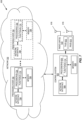
- Figure 5 illustrates the operation of a base station (e.g., base station 302 such as, e.g., a gNB) and UEs (e.g., wireless devices 312) to provide COT sharing by multiple UEs in accordance with at least some aspects of at least some of the embodiments described above.
- Optional steps are represented by dashed lines.
- Figure 5A is similar to Figure 5 , but used specifically to illustrate some optional or implicit actions referred to below in the description of Figure 5 .
- UE1 there are five UEs, denoted as UE1 through UE5.
- an uplink transmission is triggered at UE1 (step 500).
- UE1 then performs an LBT procedure (step 502).
- the LBT procedure is successful.
- UE1 transmits a message(s) to initiate or request a shared COT (step 504).
- the message(s) may include a message(s) in accordance with any one of the following example alternatives:
- the base station decides which UEs are to be assigned to a shared COT to be shared by the UE and one or more additional UEs for uplink transmission (step 505), generates COT information for the shared COT, and signals the COT information to all of the UEs, which in this example are UE1, UE2, UE3, UE4, and UE5 (step 506).
- the base station may use any appropriate scheme for deciding which UEs to assign to the shared COT. For example, the base station may select the UEs to be assigned to the shared COT based on ordinary scheduling procedures. Those UEs may have similar traffic patterns, so they may send SRs/BSRs in a burst period.
- UE1 and UE2 are assigned to the shared COT, and UE3, UE4, and UE5 are not assigned to the shared COT.
- the shared COT is also referred to herein as a UE-initiated shared COT.
- the base station determines the UEs to be assigned to the shared COT prior to generating and signaling the COT information, the present disclosure is not limited thereto.
- the COT information is generally described herein as being signaled via a single signaling message, the present disclosure is not limited thereto.
- the COT information may be signaled via two or more messages.
- the different messages may be signaled at different points in the process.
- the base station may send a portion of the COT information including, e.g., information that defines the start time and/or end time of the shared COT in step 506, thereafter receive messages (e.g., SRs and/or BSRs) from UEs that desire to use the shared COT, and then determine which of those UEs to assign to the shared COT (e.g., based on any desired criteria such as, e.g., the amount of data available for transmission at the UEs, priorities assigned to the UEs, or the like).
- messages e.g., SRs and/or BSRs
- the COT information may include, e.g., information that indicates the time when the COT starts, information that indicates the time when the COT ends, information that indicates the COT category, i.e., gNB initiated COT or UE initiated COT, information that indicates the time when a uplink/downlink switch may occur, information that indicates a maximum number of switch events between uplink and downlink, information that indicates the UEs (e.g., UE IDs) that are allowed to share (i.e., use) the COT, information (e.g., indices) that indicates services, logical channels, logical channel groups, and/or channel access priority classes that are allowed to transmit within the COT, information that indicates what control signaling and/or data is allowed to transmit within the COT, information that indicates the type(s) of LBT operations that can be used in the COT, e.g., one or more of the categories of LBT operations defined above, uplink grants associated to the UEs who are allowed to use the COT (e.g.
- the base station may signal the COT information to the UEs using any appropriate signaling such as, e.g., DCI based signaling, MAC CE based signaling, RRC signaling, or DFI.
- the types of operations that can be used are LBT type 1 or LBT type 2 depending on the switch gap. For example, if the switching gap is less than 16 ⁇ s, the UE uses Type 1/Cat 1, meaning no LBT; if the gap is larger than 16 ⁇ s, however shorter than 25 ⁇ s, the UE uses type 2 LBT, i.e., 25 ⁇ s LBT operation.
- the type(s) of LBT operations that can be used in the COT information flexibility is provided on choice of LBT operation.
- UE1 and UE2 are assigned to the shared COT, and UE3, UE4, and UE5 are not assigned to the shared COT.
- Each of the UEs receives the COT information.
- the COT information includes information that indicates which UEs are assigned to the shared COT.
- each of the UEs reads the COT information, determines whether it is assigned to the shared COT (see Figure 5A , steps 507C-507G), and optionally adapts its PDCCH monitoring and/or its DRX configuration based on whether it is assigned to the shared COT (steps 508, 510, 512, 514, 516).
- additional signaling is used to indicate to each of the UEs whether it is assigned to the shared COT, as discussed above. For example, see Figure 5A , steps 507A and 507B and note that similar indications may be sent to UE3, UE4, and UE5 to indicate that they are not assigned to the shared COT.
- the base station and the UEs assigned to the shared COT cooperate to schedule or organize uplink transmissions from those UEs during the shared COT such that the UEs share the same cell, carrier, BWP, channel, subband, or group during the shared COT (step 518).
- the uplink transmissions from those UEs during the shared COT are preferably scheduled or organized such that the gap between any two consecutive transmissions is less than a configured time period (e.g., 16 ⁇ s or 25 ⁇ s), as discussed above. In this way, either Category 1 or Category 2 LBT can be chosen to avoid latency incurred by usage of Category 4 LBT operations.
- the base station schedules the UEs that are assigned to the shared COT for uplink transmissions within the shared COT using any appropriate scheduling scheme (e.g., a conventional scheduling scheme). For example, see Figure 5A , steps 518A-518D where uplink grants are sent from the base station to UE1 and UE2 and, in response, UE1 and UE2 transmit uplink transmissions during the shared COT in accordance with the respective uplink grants.
- a conventional scheduling scheme e.g., a conventional scheduling scheme
- the UEs send SRs to the base station and the base station sends respective uplink grants to the UEs during the shared COT.
- the base station may already have sufficient information on the buffer status of each of the UEs at the time that the shared COT is determined and schedule the UEs during the shared COT accordingly.
- FIG. 6 is a schematic block diagram of a radio access node 600 according to some embodiments of the present disclosure.
- the radio access node 600 may be, for example, a base station 302 or 306.
- the radio access node 600 includes a control system 602 that includes one or more processors 604 (e.g., Central Processing Units (CPUs), Application Specific Integrated Circuits (ASICs), Field Programmable Gate Arrays (FPGAs), and/or the like), memory 606, and a network interface 608.
- the one or more processors 604 are also referred to herein as processing circuitry.
- the radio access node 600 includes one or more radio units 610 that each includes one or more transmitters 612 and one or more receivers 614 coupled to one or more antennas 616.
- the radio units 610 may be referred to or be part of radio interface circuitry.
- the radio unit(s) 610 is external to the control system 602 and connected to the control system 602 via, e.g., a wired connection (e.g., an optical cable).
- the radio unit(s) 610 and potentially the antenna(s) 616 are integrated together with the control system 602.
- the one or more processors 604 operate to provide one or more functions of a radio access node 600 (e.g., one or more functions of a gNB) as described herein.
- the function(s) are implemented in software that is stored, e.g., in the memory 606 and executed by the one or more processors 604.
- Figure 7 is a schematic block diagram that illustrates a virtualized embodiment of the radio access node 600 according to some embodiments of the present disclosure. This discussion is equally applicable to other types of network nodes. Further, other types of network nodes may have similar virtualized architectures.
- a "virtualized" radio access node is an implementation of the radio access node 600 in which at least a portion of the functionality of the radio access node 600 is implemented as a virtual component(s) (e.g., via a virtual machine(s) executing on a physical processing node(s) in a network(s)).
- the radio access node 600 includes the control system 602 that includes the one or more processors 604 (e.g., CPUs, ASICs, FPGAs, and/or the like), the memory 606, and the network interface 608 and the one or more radio units 610 that each includes the one or more transmitters 612 and the one or more receivers 614 coupled to the one or more antennas 616, as described above.
- the control system 602 is connected to the radio unit(s) 610 via, for example, an optical cable or the like.
- the control system 602 is connected to one or more processing nodes 700 coupled to or included as part of a network(s) 702 via the network interface 608.
- Each processing node 700 includes one or more processors 704 (e.g., CPUs, ASICs, FPGAs, and/or the like), memory 706, and a network interface 708.
- functions 710 of the radio access node 600 are implemented at the one or more processing nodes 700 or distributed across the control system 602 and the one or more processing nodes 700 in any desired manner.
- some or all of the functions 710 of the radio access node 600 described herein are implemented as virtual components executed by one or more virtual machines implemented in a virtual environment(s) hosted by the processing node(s) 700.
- additional signaling or communication between the processing node(s) 700 and the control system 602 is used in order to carry out at least some of the desired functions 710.
- the control system 602 may not be included, in which case the radio unit(s) 610 communicate directly with the processing node(s) 700 via an appropriate network interface(s).
- a computer program including instructions which, when executed by at least one processor, causes the at least one processor to carry out the functionality of radio access node 600 (e.g., one or more functions of a gNB) or a node (e.g., a processing node 700) implementing one or more of the functions 710 of the radio access node 600 (e.g., one or more functions of a gNB) in a virtual environment according to any of the embodiments described herein is provided.
- a carrier comprising the aforementioned computer program product is provided.
- the carrier is one of an electronic signal, an optical signal, a radio signal, or a computer readable storage medium (e.g., a non-transitory computer readable medium such as memory).
- FIG 8 is a schematic block diagram of the radio access node 600 according to some other embodiments of the present disclosure.
- the radio access node 600 includes one or more modules 800, each of which is implemented in software.
- the module(s) 800 provide the functionality of the radio access node 600 (e.g., one or more functions of a gNB) described herein.
- This discussion is equally applicable to the processing node 700 of Figure 7 where the modules 800 may be implemented at one of the processing nodes 700 or distributed across multiple processing nodes 700 and/or distributed across the processing node(s) 700 and the control system 602.
- FIG. 9 is a schematic block diagram of a UE 900 according to some embodiments of the present disclosure.
- the UE 900 includes one or more processors 902 (e.g., CPUs, ASICs, FPGAs, and/or the like), memory 904, and one or more transceivers 906 each including one or more transmitters 908 and one or more receivers 910 coupled to one or more antennas 912.
- the transceiver(s) 906 includes radio-front end circuitry connected to the antenna(s) 912 that is configured to condition signals communicated between the antenna(s) 912 and the processor(s) 902, as will be appreciated by on of ordinary skill in the art.
- the processors 902 are also referred to herein as processing circuitry.
- the transceivers 906 are also referred to herein as radio circuitry.
- the functionality of the UE 900 described above may be fully or partially implemented in software that is, e.g., stored in the memory 904 and executed by the processor(s) 902.
- the UE 900 may include additional components not illustrated in Figure 9 such as, e.g., one or more user interface components (e.g., an input/output interface including a display, buttons, a touch screen, a microphone, a speaker(s), and/or the like and/or any other components for allowing input of information into the UE 900 and/or allowing output of information from the UE 900), a power supply (e.g., a battery and associated power circuitry), etc.
- a power supply e.g., a battery and associated power circuitry
- a computer program including instructions which, when executed by at least one processor, causes the at least one processor to carry out the functionality of the UE 900 according to any of the embodiments described herein is provided.
- a carrier comprising the aforementioned computer program product is provided.
- the carrier is one of an electronic signal, an optical signal, a radio signal, or a computer readable storage medium (e.g., a non-transitory computer readable medium such as memory).
- FIG 10 is a schematic block diagram of the UE 900 according to some other embodiments of the present disclosure.
- the UE 900 includes one or more modules 1000, each of which is implemented in software.
- the module(s) 1000 provide the functionality of the UE 900 described herein.
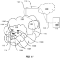
- a communication system includes a telecommunication network 1100, such as a 3GPP-type cellular network, which comprises an access network 1102, such as a RAN, and a core network 1104.
- the access network 1102 comprises a plurality of base stations 1106A, 1106B, 1106C, such as NBs, eNBs, gNBs, or other types of wireless APs, each defining a corresponding coverage area 1108A, 1108B, 1108C.
- Each base station 1106A, 1106B, 1106C is connectable to the core network 1104 over a wired or wireless connection 1110.
- a first UE 1112 located in coverage area 1108C is configured to wirelessly connect to, or be paged by, the corresponding base station 1106C.
- a second UE 1114 in coverage area 1108A is wirelessly connectable to the corresponding base station 1106A. While a plurality of UEs 1112, 1114 are illustrated in this example, the disclosed embodiments are equally applicable to a situation where a sole UE is in the coverage area or where a sole UE is connecting to the corresponding base station 1106.
- the telecommunication network 1100 is itself connected to a host computer 1116, which may be embodied in the hardware and/or software of a standalone server, a cloud-implemented server, a distributed server, or as processing resources in a server farm.
- the host computer 1116 may be under the ownership or control of a service provider, or may be operated by the service provider or on behalf of the service provider.
- Connections 1118 and 1120 between the telecommunication network 1100 and the host computer 1116 may extend directly from the core network 1104 to the host computer 1116 or may go via an optional intermediate network 1122.
- the intermediate network 1122 may be one of, or a combination of more than one of, a public, private, or hosted network; the intermediate network 1122, if any, may be a backbone network or the Internet; in particular, the intermediate network 1122 may comprise two or more sub-networks (not shown).
- the communication system of Figure 11 as a whole enables connectivity between the connected UEs 1112, 1114 and the host computer 1116.
- the connectivity may be described as an Over-the-Top (OTT) connection 1124.
- the host computer 1116 and the connected UEs 1112, 1114 are configured to communicate data and/or signaling via the OTT connection 1124, using the access network 1102, the core network 1104, any intermediate network 1122, and possible further infrastructure (not shown) as intermediaries.
- the OTT connection 1124 may be transparent in the sense that the participating communication devices through which the OTT connection 1124 passes are unaware of routing of uplink and downlink communications.
- the base station 1106 may not or need not be informed about the past routing of an incoming downlink communication with data originating from the host computer 1116 to be forwarded (e.g., handed over) to a connected UE 1112. Similarly, the base station 1106 need not be aware of the future routing of an outgoing uplink communication originating from the UE 1112 towards the host computer 1116.
- a host computer 1202 comprises hardware 1204 including a communication interface 1206 configured to set up and maintain a wired or wireless connection with an interface of a different communication device of the communication system 1200.
- the host computer 1202 further comprises processing circuitry 1208, which may have storage and/or processing capabilities.
- the processing circuitry 1208 may comprise one or more programmable processors, ASICs, FPGAs, or combinations of these (not shown) adapted to execute instructions.
- the host computer 1202 further comprises software 1210, which is stored in or accessible by the host computer 1202 and executable by the processing circuitry 1208.
- the software 1210 includes a host application 1212.
- the host application 1212 may be operable to provide a service to a remote user, such as a UE 1214 connecting via an OTT connection 1216 terminating at the UE 1214 and the host computer 1202.
- the host application 1212 may provide user data which is transmitted using the OTT connection 1216.
- the communication system 1200 further includes a base station 1218 provided in a telecommunication system and comprising hardware 1220 enabling it to communicate with the host computer 1202 and with the UE 1214.
- the hardware 1220 may include a communication interface 1222 for setting up and maintaining a wired or wireless connection with an interface of a different communication device of the communication system 1200, as well as a radio interface 1224 for setting up and maintaining at least a wireless connection 1226 with the UE 1214 located in a coverage area (not shown in Figure 12 ) served by the base station 1218.
- the communication interface 1222 may be configured to facilitate a connection 1228 to the host computer 1202.
- connection 1228 may be direct or it may pass through a core network (not shown in Figure 12 ) of the telecommunication system and/or through one or more intermediate networks outside the telecommunication system.
- the hardware 1220 of the base station 1218 further includes processing circuitry 1230, which may comprise one or more programmable processors, ASICs, FPGAs, or combinations of these (not shown) adapted to execute instructions.
- the base station 1218 further has software 1232 stored internally or accessible via an external connection.
- the communication system 1200 further includes the UE 1214 already referred to.
- the UE's 1214 hardware 1234 may include a radio interface 1236 configured to set up and maintain a wireless connection 1226 with a base station serving a coverage area in which the UE 1214 is currently located.
- the hardware 1234 of the UE 1214 further includes processing circuitry 1238, which may comprise one or more programmable processors, ASICs, FPGAs, or combinations of these (not shown) adapted to execute instructions.
- the UE 1214 further comprises software 1240, which is stored in or accessible by the UE 1214 and executable by the processing circuitry 1238.
- the software 1240 includes a client application 1242.
- the client application 1242 may be operable to provide a service to a human or non-human user via the UE 1214, with the support of the host computer 1202.
- the executing host application 1212 may communicate with the executing client application 1242 via the OTT connection 1216 terminating at the UE 1214 and the host computer 1202.
- the client application 1242 may receive request data from the host application 1212 and provide user data in response to the request data.
- the OTT connection 1216 may transfer both the request data and the user data.
- the client application 1242 may interact with the user to generate the user data that it provides.
- the host computer 1202, the base station 1218, and the UE 1214 illustrated in Figure 12 may be similar or identical to the host computer 1116, one of the base stations 1106A, 1106B, 1106C, and one of the UEs 1112, 1114 of Figure 11 , respectively.
- the inner workings of these entities may be as shown in Figure 12 and independently, the surrounding network topology may be that of Figure 11 .
- the OTT connection 1216 has been drawn abstractly to illustrate the communication between the host computer 1202 and the UE 1214 via the base station 1218 without explicit reference to any intermediary devices and the precise routing of messages via these devices.
- the network infrastructure may determine the routing, which may be configured to hide from the UE 1214 or from the service provider operating the host computer 1202, or both. While the OTT connection 1216 is active, the network infrastructure may further take decisions by which it dynamically changes the routing (e.g., on the basis of load balancing consideration or reconfiguration of the network).
- the wireless connection 1226 between the UE 1214 and the base station 1218 is in accordance with the teachings of the embodiments described throughout this disclosure.
- One or more of the various embodiments improve the performance of OTT services provided to the UE 1214 using the OTT connection 1216, in which the wireless connection 1226 forms the last segment. More precisely, the teachings of these embodiments may improve data rate, latency, and/or power consumption and thereby provide benefits such as, e.g., reduced user waiting time, relaxed restriction on file size, better responsiveness, and/or extended battery lifetime.
- sensors may be deployed in or in association with communication devices through which the OTT connection 1216 passes; the sensors may participate in the measurement procedure by supplying values of the monitored quantities exemplified above, or supplying values of other physical quantities from which the software 1210, 1240 may compute or estimate the monitored quantities.
- the reconfiguring of the OTT connection 1216 may include message format, retransmission settings, preferred routing, etc.; the reconfiguring need not affect the base station 1218, and it may be unknown or imperceptible to the base station 1218. Such procedures and functionalities may be known and practiced in the art.
- measurements may involve proprietary UE signaling facilitating the host computer 1202's measurements of throughput, propagation times, latency, and the like. The measurements may be implemented in that the software 1210 and 1240 causes messages to be transmitted, in particular empty or 'dummy' messages, using the OTT connection 1216 while it monitors propagation times, errors, etc.
- FIG. 13 is a flowchart illustrating a method implemented in a communication system, in accordance with one embodiment.
- the communication system includes a host computer, a base station, and a UE which may be those described with reference to Figures 11 and 12 .
- the host computer provides user data.
- sub-step 1302 (which may be optional) of step 1300, the host computer provides the user data by executing a host application.
- the host computer initiates a transmission carrying the user data to the UE.
- step 1306 the base station transmits to the UE the user data which was carried in the transmission that the host computer initiated, in accordance with the teachings of the embodiments described throughout this disclosure.
- step 1308 the UE executes a client application associated with the host application executed by the host computer.
- FIG 14 is a flowchart illustrating a method implemented in a communication system, in accordance with one embodiment.
- the communication system includes a host computer, a base station, and a UE which may be those described with reference to Figures 11 and 12 .
- the host computer provides user data.
- the host computer provides the user data by executing a host application.
- the host computer initiates a transmission carrying the user data to the UE.
- the transmission may pass via the base station, in accordance with the teachings of the embodiments described throughout this disclosure.
- step 1404 (which may be optional), the UE receives the user data carried in the transmission.
- FIG. 15 is a flowchart illustrating a method implemented in a communication system, in accordance with one embodiment.
- the communication system includes a host computer, a base station, and a UE which may be those described with reference to Figures 11 and 12 .
- the UE receives input data provided by the host computer. Additionally or alternatively, in step 1502, the UE provides user data.
- sub-step 1504 (which may be optional) of step 1500, the UE provides the user data by executing a client application.
- sub-step 1506 (which may be optional) of step 1502
- the UE executes a client application which provides the user data in reaction to the received input data provided by the host computer.
- the executed client application may further consider user input received from the user.
- the UE initiates, in sub-step 1508 (which may be optional), transmission of the user data to the host computer.
- step 1510 of the method the host computer receives the user data transmitted from the UE, in accordance with the teachings of the embodiments described throughout this disclosure.
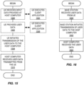
- FIG 16 is a flowchart illustrating a method implemented in a communication system, in accordance with one embodiment.
- the communication system includes a host computer, a base station, and a UE which may be those described with reference to Figures 11 and 12 .
- the base station receives user data from the UE.
- the base station initiates transmission of the received user data to the host computer.
- the host computer receives the user data carried in the transmission initiated by the base station.
- any appropriate steps, methods, features, functions, or benefits disclosed herein may be performed through one or more functional units or modules of one or more virtual apparatuses.
- Each virtual apparatus may comprise a number of these functional units.
- These functional units may be implemented via processing circuitry, which may include one or more microprocessor or microcontrollers, as well as other digital hardware, which may include Digital Signal Processor (DSPs), special-purpose digital logic, and the like.
- the processing circuitry may be configured to execute program code stored in memory, which may include one or several types of memory such as Read Only Memory (ROM), Random Access Memory (RAM), cache memory, flash memory devices, optical storage devices, etc.
- Program code stored in memory includes program instructions for executing one or more telecommunications and/or data communications protocols as well as instructions for carrying out one or more of the techniques described herein.
- the processing circuitry may be used to cause the respective functional unit to perform corresponding functions according one or more embodiments of the present disclosure.
Landscapes
- Engineering & Computer Science (AREA)
- Computer Networks & Wireless Communication (AREA)
- Signal Processing (AREA)
- Mobile Radio Communication Systems (AREA)
Claims (21)
- Procédé réalisé par un dispositif sans fil (312 ; UE1) pour un partage initié par dispositif sans fil d'un temps d'occupation de canal, COT, dans un système sans fil (300) fonctionnant dans un spectre sans licence, le procédé comprenant :la réalisation (502) d'une procédure Listen-Before-Talk, LBT, dont un résultat est un succès LBT ;la transmission (504), à une station de base (302), d'un ou plusieurs messages qui initient un partage COT entre le dispositif sans fil (312 ; UE1) et un ou plusieurs dispositifs sans fil supplémentaires, dans lequel les un ou plusieurs messages qui initient un partage COT comprennent :une demande de planification comprenant des informations qui indiquent : (a) un ou plusieurs services, un ou plusieurs canaux logiques, ou un ou plusieurs groupes de canaux logiques avec des données disponibles au niveau du dispositif sans fil (312 ; UE1) pour être transmises et (b) un statut de mémoire tampon des données disponibles au niveau du dispositif sans fil (312 ; UE1) pour être transmises ; oudes messages pour une procédure d'accès aléatoire à deux étapes comprenant un message qui comprend au moins un rapport de statut de mémoire tampon pour des données disponibles au niveau du dispositif sans fil (312 ; UE1) pour être transmises ; ouune demande de planification et un ou plusieurs rapports de statut de mémoire tampon suivants pour des données disponibles au niveau du dispositif sans fil (312 ; UE1) pour être transmises ; ouun ou plusieurs messages comprenant des informations de commande de liaison montante, les informations de commande de liaison montante comprenant un rapport de statut de mémoire tampon pour des données disponibles au niveau du dispositif sans fil (312 ; UE1) pour être transmises ;la réception (506) d'informations COT depuis la station de base (302), les informations COT étant des informations relatives à un COT partagé à utiliser par le dispositif sans fil (312 ; UE1) et un ou plusieurs dispositifs sans fil supplémentaires ; etla coopération (518) avec la station de base (302) pour utiliser le COT partagé.
- Procédé selon la revendication 1, dans lequel les informations COT comprennent :a) des informations qui indiquent un temps de début du COT partagé ; oub) des informations qui indiquent un temps de fin du COT partagé ; ouc) des informations qui indiquent une catégorie de COT du COT partagé ; oud) des informations qui indiquent un ou plusieurs temps auxquels une commutation de liaison montante/liaison descendante peut survenir au cours du COT partagé ; oue) des informations qui indiquent un nombre maximal d'événements de commutation entre une liaison montante et une liaison descendante au cours du COT partagé ; ouf) des informations qui indiquent un ensemble de dispositifs sans fil qui sont autorisés à partager le COT partagé, l'ensemble de dispositifs sans fil comprenant le dispositif sans fil (312 ; UE1) et un ou plusieurs dispositifs sans fil supplémentaire ; oug) des informations qui indiquent des services, des canaux logiques, des groupes de canaux logiques et/ou des classes de priorité d'accès de canal qui sont autorisés à transmettre à l'intérieur du COT partagé ; ouh) des informations qui indiquent une signalisation de commande et/ou des données qui sont autorisées à être transmises à l'intérieur du COT partagé ; oui) des informations qui indiquent un ou plusieurs types d'opérations Listen-Before-Talk, LBT, qui peuvent être utilisées dans le COT partagé ; ouj) des octrois de liaison montante associés à des dispositifs sans fil dans l'ensemble de dispositifs sans fil qui sont autorisés à partager le COT partagé ; ouk) des informations qui indiquent des positions de temps réservées pour des transmissions de signaux de référence de démodulation potentielles ; oul) toute combinaison d'au moins deux de (a) à (k).
- Procédé selon la revendication 1 ou 2, comprenant en outre :la détermination (507C) que le dispositif sans fil (312 ; UE1) est attribué au COT partagé ; etl'adaptation (508) d'une surveillance de canal de commande de liaison descendante physique par le dispositif sans fil (312 ; UE1) sur la base de la détermination que le dispositif sans fil (312 ; UE1) est attribué au COT partagé.
- Procédé selon la revendication 3, dans lequel la détermination (507C) que le dispositif sans fil (312 ; UE1) est attribué au COT partagé comprend la détermination (507C) que le dispositif sans fil (312 ; UE1) est attribué au COT partagé sur la base d'informations comprises dans le COT partagé qui indiquent que le dispositif sans fil (312 ; UE1) est l'un d'un ensemble de dispositifs sans fil autorisés à partager le COT partagé.
- Procédé selon la revendication 3, comprenant en outre :la réception (507A), depuis la station de base (302), d'une indication que le dispositif sans fil (312 ; UE1) est autorisé à partager le COT partagé ;dans lequel la détermination (507C) que le dispositif sans fil (312 ; UE1) est attribué au COT partagé comprend la détermination (507C) que le dispositif sans fil (312 ; UE1) est attribué au COT partagé sur la base de l'indication reçue.
- Procédé selon l'une quelconque des revendications 3 à 5, dans lequel l'adaptation (508) d'une surveillance de canal de commande de liaison descendante physique par le dispositif sans fil (312 ; UE1) sur la base de la détermination que le dispositif sans fil (312 ; UE1) est attribué au COT partagé comprend l'augmentation de la fréquence à laquelle le dispositif sans fil (312 ; UE1) surveille une transmission de canal de commande de liaison descendante physique depuis la station de base (302) au cours du COT partagé.
- Procédé selon la revendication 3, dans lequel l'adaptation (508) d'une surveillance de canal de commande de liaison descendante physique par le dispositif sans fil (312 ; UE1) sur la base de la détermination si le dispositif sans fil (312 ; UE1) est attribué au COT partagé comprend la commutation d'un motif de surveillance de canal de commande de liaison descendante physique d'un premier motif à un deuxième motif, dans lequel le deuxième motif présente des occasions de surveillance de canal de commande de liaison descendante physique différentes de celles du premier motif.
- Procédé selon l'une quelconque des revendications 1 à 7, dans lequel la réception (506) des informations COT depuis la station de base (302) comprend la réception (506) des informations COT depuis la station de base (302) par l'intermédiaire de l'un quelconque des types suivants de signalisation :• signalisation basée sur informations de commande de liaison descendante ; ou• signalisation basée sur élément de commande, CE, de commande d'accès au support, MAC ; ou• signalisation de couche supérieure ; ou• signalisation de rétroaction de liaison descendante.
- Dispositif sans fil (312 ; UE1) pour un partage initié par dispositif sans fil d'un temps d'occupation de canal, COT, dans un système sans fil (300) fonctionnant dans un spectre sans licence, le dispositif sans fil (312 ; UE1) étant adapté pour :réaliser (502) une procédure Listen-Before-Talk, LBT, dont un résultat est un succès LBT ;transmettre (504), à une station de base (302), un ou plusieurs messages qui initient un partage COT entre le dispositif sans fil (312 ; UE1) et un ou plusieurs dispositifs sans fil supplémentaires, dans lequel les un ou plusieurs messages qui initient un partage COT comprennent :une demande de planification comprenant des informations qui indiquent : (a) un ou plusieurs services, un ou plusieurs canaux logiques, ou un ou plusieurs groupes de canaux logiques avec des données disponibles au niveau du dispositif sans fil (312 ; UE1) pour être transmises et (b) un statut de mémoire tampon des données disponibles au niveau du dispositif sans fil (312 ; UE1) pour être transmises ; oudes messages pour une procédure d'accès aléatoire à deux étapes comprenant un message qui comprend au moins un rapport de statut de mémoire tampon pour des données disponibles au niveau du dispositif sans fil (312 ; UE1) pour être transmises ; ouune demande de planification et un ou plusieurs rapports de statut de mémoire tampon suivants pour des données disponibles au niveau du dispositif sans fil (312 ; UE1) pour être transmises ; ouun ou plusieurs messages comprenant des informations de commande de liaison montante, les informations de commande de liaison montante comprenant un rapport de statut de mémoire tampon pour des données disponibles au niveau du dispositif sans fil (312 ; UE1) pour être transmises ;recevoir (506) des informations COT depuis la station de base (302), les informations COT étant des informations relatives à un COT partagé à utiliser par le dispositif sans fil (312 ; UE1) et un ou plusieurs dispositifs sans fil supplémentaires ; etcoopérer (518) avec la station de base (302) pour utiliser le COT partagé.
- Dispositif sans fil (312 ; UE1) selon la revendication 9, dans lequel le dispositif sans fil (312 ; UE1) est en outre adapté pour réaliser le procédé selon l'une quelconque des revendications 2 à 8.
- Procédé réalisé par une station de base (302 ; BS) pour un partage initié par dispositif sans fil d'un temps d'occupation de canal, COT, dans un système sans fil (300) fonctionnant dans un spectre sans licence, le procédé comprenant :
la réception (504), depuis un dispositif sans fil (312 ; UE1), d'un ou plusieurs messages qui initient un partage COT entre le dispositif sans fil (312 ; UE1) et un ou plusieurs dispositifs sans fil supplémentaires, dans lequel les un ou plusieurs messages qui initient un partage COT comprennent :une demande de planification comprenant des informations qui indiquent : (a) un ou plusieurs services, un ou plusieurs canaux logiques, ou un ou plusieurs groupes de canaux logiques avec des données disponibles au niveau du dispositif sans fil (312 ; UE1) pour être transmises et (b) un statut de mémoire tampon des données disponibles au niveau du dispositif sans fil (312 ; UE1) pour être transmises ; ouun ou plusieurs messages pour une procédure d'accès aléatoire à deux étapes comprenant un message qui comprend au moins un rapport de statut de mémoire tampon pour des données disponibles au niveau du dispositif sans fil (312 ; UE1) pour être transmises ; ouune demande de planification et un ou plusieurs rapports de statut de mémoire tampon suivants pour des données disponibles au niveau du dispositif sans fil (312 ; UE1) pour être transmises ; ouun ou plusieurs messages comprenant des informations de commande de liaison montante, les informations de commande de liaison montante comprenant un rapport de statut de mémoire tampon pour des données disponibles au niveau du dispositif sans fil (312 ; UE1) pour être transmises ;la transmission (506) d'informations COT, les informations COT étant des informations relatives à un COT partagé à utiliser par un ensemble de dispositifs sans fil attribués au COT partagé, dans lequel l'ensemble de dispositifs sans fil attribués au COT partagé comprend le dispositif sans fil (312 ; UE1) et un ou plusieurs dispositifs sans fil (312 ; UE2) supplémentaires ; etla coopération (518) avec les dispositifs sans fil (312 ; UE1 et UE2) dans l'ensemble de dispositifs sans fil attribués pour utiliser le COT partagé pendant le COT partagé. - Procédé selon la revendication 11, dans lequel les informations COT comprennent :a) des informations qui indiquent un temps de début du COT partagé ;b) des informations qui indiquent un temps de fin du COT partagé ;c) des informations qui indiquent une catégorie de COT du COT partagé ;d) des informations qui indiquent un ou plusieurs temps auxquels une commutation de liaison montante/liaison descendante peut survenir au cours du COT partagé ;e) des informations qui indiquent un nombre maximal d'événements de commutation entre une liaison montante et une liaison descendante au cours du COT partagé ;f) des informations qui indiquent un ensemble de dispositifs sans fil qui sont autorisés à partager le COT partagé, l'ensemble de dispositifs sans fil comprenant le dispositif sans fil (312 ; UE1) et un ou plusieurs dispositifs sans fil (312 ; UE2) supplémentaire ;g) des informations qui indiquent des services, des canaux logiques, des groupes de canaux logiques et/ou des classes de priorité d'accès de canal qui sont autorisés à transmettre à l'intérieur du COT partagé ;h) des informations qui indiquent une signalisation de commande et/ou des données qui sont autorisées à être transmises à l'intérieur du COT partagé ;i) des informations qui indiquent un ou plusieurs types d'opérations Listen-Before-Talk, LBT, qui peuvent être utilisées dans le COT partagé ;j) des octrois de liaison montante associés à des dispositifs sans fil dans l'ensemble de dispositifs sans fil qui sont autorisés à partager le COT partagé ;k) des informations qui indiquent des positions de temps réservées pour des transmissions de signaux de référence de démodulation potentielles ; oul) toute combinaison d'au moins deux de (a) à (k).
- Procédé selon la revendication 11 ou 12, dans lequel la coopération (518) avec les dispositifs sans fil (312 ; UE1 et UE2) dans l'ensemble de dispositifs sans fil attribués au COT partagé pour utiliser le COT partagé comprend la coopération (518) avec les dispositifs sans fil (312 ; UE1 et UE2) dans l'ensemble de dispositifs sans fil attribués au COT partagé pour planifier et organiser des transmissions depuis les dispositifs sans fil (312 ; UE1 et UE2) au cours du COT partagé.
- Procédé selon la revendication 13, dans lequel la coopération (518) avec les dispositifs sans fil (312 ; UE1 et UE2) dans l'ensemble de dispositifs sans fil attribués au COT partagé pour planifier et organiser des transmissions depuis les dispositifs sans fil (312 ; UE1 et UE2) au cours du COT partagé comprend :la transmission (518A, 518B), aux dispositifs sans fil (312 ; UE1 et UE2) dans l'ensemble de dispositifs sans fil attribués au COT partagé, d'octrois de liaison montante respectifs pour des transmissions de liaison montante par les dispositifs sans fil (312 ; UE1 et UE2) au cours du COT partagé ; etla réception (518C, 518D) des transmissions de liaison montante depuis les dispositifs sans fil (312 ; UE1 et UE2) au cours du COT partagé en fonction des octrois de liaison montante.
- Procédé selon la revendication 13 ou 14, dans lequel la coopération (518) avec les dispositifs sans fil (312 ; UE1 et UE2) dans l'ensemble de dispositifs sans fil attribués au COT partagé pour planifier et organiser des transmissions depuis les dispositifs sans fil (312 ; UE1 et UE2) au cours du COT partagé comprend la coopération (518) avec les dispositifs sans fil (312 ; UE1 et UE2) de sorte que des transmissions de liaison montante par les dispositifs sans fil (312 ; UE1 et UE2) soient planifiées et organisées de telle manière que les dispositifs sans fil (312 ; UE1 et UE2) attribués au COT partagé partagent le COT partagé.
- Procédé selon la revendication 15, dans lequel la coopération (518) avec les dispositifs sans fil (312 ; UE1 et UE2) de sorte que des transmissions de liaison montante par les dispositifs sans fil (312 ; UE1 et UE2) soient planifiées et organisées de telle manière que les dispositifs sans fil (312 ; UE1 et UE2) attribués au COT partagé partagent le COT partagé comprend la coopération (518) avec les dispositifs sans fil (312 ; UE1 et UE2) de sorte qu'une transmission de liaison montante depuis l'un des dispositifs sans fil (312 ; UE1) au cours du COT partagé ne bloque pas une transmission de liaison montante depuis les autres dispositifs sans fil (312 ; UE2) au cours du COT partagé.
- Procédé selon la revendication 15, dans lequel la coopération (518) avec les dispositifs sans fil (312 ; UE1 et UE2) de sorte que des transmissions de liaison montante par les dispositifs sans fil (312 ; UE1 et UE2) soient planifiées et organisées de telle manière que les dispositifs sans fil (312 ; UE1 et UE2) attribués au COT partagé partagent le COT partagé comprend la coopération (518) avec les dispositifs sans fil (312 ; UE1 et UE2) de sorte qu'une transmission de liaison montante depuis l'un des dispositifs sans fil (312 ; UE1) au cours du COT partagé survienne en même temps qu'une transmission de liaison montante depuis les autres dispositifs sans fil (312 ; UE2) au cours du COT partagé, en utilisant des ressources différentes.
- Procédé selon l'une quelconque des revendications 11 à 17, dans lequel la coopération (518) avec les dispositifs sans fil (312 ; UE1 et UE2) dans l'ensemble de dispositifs sans fil attribués au COT partagé pour planifier et organiser des transmissions depuis les dispositifs sans fil (312 ; UE1 et UE2) au cours du COT partagé comprend la coopération (518) avec des dispositifs sans fil (312 ; UE1 et UE2) de sorte qu'un intervalle entre deux transmissions de liaison montante consécutives par les dispositifs sans fil (312 ; UE1 et UE2) attribués qui surviennent au cours du COT partagé soit inférieur à une période de temps configurée.
- Procédé selon la revendication 18, dans lequel la période de temps configurée est soit 16 microsecondes, ps, soit 25 ps.
- Station de base (302 ; BS) pour un partage initié par dispositif sans fil d'un temps d'occupation de canal, COT, dans un système sans fil (300) fonctionnant dans un spectre sans licence, la station de base (302 ; BS) étant adaptée pour :
recevoir (504), depuis un dispositif sans fil (312 ; UE1), un ou plusieurs messages qui initient un partage COT entre le dispositif sans fil (312 ; UE1) et un ou plusieurs dispositifs sans fil supplémentaires, dans laquelle les un ou plusieurs messages qui initient un partage COT comprennent :une demande de planification comprenant des informations qui indiquent : (a) un ou plusieurs services, un ou plusieurs canaux logiques, ou un ou plusieurs groupes de canaux logiques avec des données disponibles au niveau du dispositif sans fil (312 ; UE1) pour être transmises et (b) un statut de mémoire tampon des données disponibles au niveau du dispositif sans fil (312 ; UE1) pour être transmises ; ouun ou plusieurs messages pour une procédure d'accès aléatoire à deux étapes comprenant un message qui comprend au moins un rapport de statut de mémoire tampon pour des données disponibles au niveau du dispositif sans fil (312 ; UE1) pour être transmises ; ouune demande de planification et un ou plusieurs rapports de statut de mémoire tampon suivants pour des données disponibles au niveau du dispositif sans fil (312 ; UE1) pour être transmises ; ouun ou plusieurs messages comprenant des informations de commande de liaison montante, les informations de commande de liaison montante comprenant un rapport de statut de mémoire tampon pour des données disponibles au niveau du dispositif sans fil (312 ; UE1) pour être transmises ;transmettre (506) des informations COT, les informations COT étant des informations relatives à un COT partagé à utiliser par un ensemble de dispositifs sans fil attribués au COT partagé, dans laquelle l'ensemble de dispositifs sans fil attribués au COT partagé comprend le dispositif sans fil (312 ; UE1) et un ou plusieurs dispositifs sans fil (312 ; UE2) supplémentaires ; etcoopérer (518) avec les dispositifs sans fil (312 ; UE1 et UE2) dans l'ensemble de dispositifs sans fil attribués au COT partagé pour utiliser le COT partagé. - Station de base (302 ; BS) selon la revendication 20, dans laquelle la station de base (302 ; BS) est en outre adaptée pour réaliser le procédé selon l'une quelconque des revendications 12 à 19.
Applications Claiming Priority (2)
| Application Number | Priority Date | Filing Date | Title |
|---|---|---|---|
| US201962802422P | 2019-02-07 | 2019-02-07 | |
| PCT/SE2019/051237 WO2020162804A1 (fr) | 2019-02-07 | 2019-12-06 | Partage de temps d'occupation de canal (cot) initié par un équipement utilisateur entre de multiples équipements utilisateurs |
Publications (2)
| Publication Number | Publication Date |
|---|---|
| EP3922075A1 EP3922075A1 (fr) | 2021-12-15 |
| EP3922075B1 true EP3922075B1 (fr) | 2024-06-19 |
Family
ID=69005794
Family Applications (1)
| Application Number | Title | Priority Date | Filing Date |
|---|---|---|---|
| EP19827854.1A Active EP3922075B1 (fr) | 2019-02-07 | 2019-12-06 | Partage de temps d'occupation de canal (cot) initié par un équipement utilisateur entre de multiples équipements utilisateurs |
Country Status (3)
| Country | Link |
|---|---|
| US (1) | US12058733B2 (fr) |
| EP (1) | EP3922075B1 (fr) |
| WO (1) | WO2020162804A1 (fr) |
Families Citing this family (49)
| Publication number | Priority date | Publication date | Assignee | Title |
|---|---|---|---|---|
| EP3895497B1 (fr) * | 2019-02-12 | 2024-07-24 | Apple Inc. | Mode de fonctionnement d'équipement basé sur une trame pour des systèmes et réseaux sans licence new radio |
| EP4274287B1 (fr) * | 2019-02-13 | 2025-04-30 | Apple Inc. | Structure de temps d'occupation de canal (cot) dans des systèmes de nouvelle radio (nr) fonctionnant sur un spectre sans licence |
| EP3927023B1 (fr) * | 2019-02-13 | 2024-09-11 | Beijing Xiaomi Mobile Software Co., Ltd. | Procédé et appareil d'utilisation d'un mode de signalisation d'économie d'énergie et terminal |
| US12089253B2 (en) * | 2019-02-15 | 2024-09-10 | Apple Inc. | System and method for channel occupancy time (COT) sharing in an unlicensed spectrum |
| US20220183069A1 (en) * | 2019-03-27 | 2022-06-09 | Ntt Docomo, Inc. | User equipment |
| EP3949657A1 (fr) * | 2019-03-28 | 2022-02-09 | Apple Inc. | Conception et appareil pour le cadre fbe pour des systèmes nr fonctionnant sur un spectre sans licence |
| KR102954883B1 (ko) * | 2019-07-22 | 2026-04-17 | 삼성전자주식회사 | 무선 통신 시스템에서 상향링크 제어 정보 전송 방법 및 장치 |
| KR20250084249A (ko) * | 2019-07-25 | 2025-06-10 | 프라운호퍼 게젤샤프트 쭈르 푀르데룽 데어 안겐반텐 포르슝 에. 베. | 송신기 cot 내에서 구성된 승인 |
| JP7671735B2 (ja) * | 2019-08-13 | 2025-05-02 | インターデイジタル パテント ホールディングス インコーポレイテッド | 共有チャネル占有時間動作 |
| US12389451B2 (en) * | 2019-08-27 | 2025-08-12 | Lenovo (Beijing) Limited | PDCCH transmission in UE-initiated COT |
| US11672034B2 (en) * | 2019-09-25 | 2023-06-06 | Qualcomm Incorporated | Channel occupancy time (COT) sharing for sidelink |
| WO2021088055A1 (fr) * | 2019-11-08 | 2021-05-14 | Oppo广东移动通信有限公司 | Procédé et appareil de transmission de données sur un spectre sans licence, dispositif et support de stockage |
| US12376153B2 (en) * | 2019-12-24 | 2025-07-29 | Qualcomm Incorporated | Signaling for channel occupancy time sharing in frame based equipment mode |
| CN114946255B (zh) * | 2020-01-23 | 2025-01-14 | 高通股份有限公司 | 在基于帧的设备模式中作为发起设备的用户设备 |
| WO2021159370A1 (fr) * | 2020-02-13 | 2021-08-19 | Qualcomm Incorporated | Transmission de données de liaison montante au début d'une période de trame fixe dans un mode d'équipement basé sur une trame |
| KR20220139290A (ko) * | 2020-02-21 | 2022-10-14 | 지티이 코포레이션 | 비허가 대역의 데이터 송신의 방법 |
| US12452906B2 (en) * | 2020-03-27 | 2025-10-21 | Lenovo (Beijing) Ltd. | Method and apparatus for channel access |
| WO2021255673A1 (fr) * | 2020-06-17 | 2021-12-23 | Lenovo (Singapore) Pte. Ltd. | Partage de temps d'occupation de canal |
| CN113852964A (zh) * | 2020-06-28 | 2021-12-28 | 索尼公司 | 电子设备、无线通信方法和非暂态计算机可读存储介质 |
| JP7563801B2 (ja) | 2020-08-07 | 2024-10-08 | ウィルス インスティテュート オブ スタンダーズ アンド テクノロジー インコーポレイティド | 無線通信システムにおいて上りリンクチャネルを送信する方法及びそのための装置 |
| US20240032092A1 (en) * | 2020-08-18 | 2024-01-25 | Mediatek Singapore Pte. Ltd. | Uplink Enhancements For URLLC And IIoT In Unlicensed Band |
| US12501486B2 (en) | 2020-08-21 | 2025-12-16 | Lenovo (Beijing) Limited | Methods and apparatus for sharing channel occupancy time for sidelink transmission |
| US12200707B2 (en) * | 2020-10-05 | 2025-01-14 | Qualcomm Incorporated | Traffic aware regular buffer status reports |
| CN114946260A (zh) * | 2020-10-15 | 2022-08-26 | 北京小米移动软件有限公司 | 通信方法及装置、网络设备、用户设备及存储介质 |
| WO2022077331A1 (fr) * | 2020-10-15 | 2022-04-21 | Apple Inc. | Occupation de canal déclenchée par un dispositif sans fil dans un spectre sans licence |
| CN114374487B (zh) * | 2020-10-15 | 2023-05-26 | 维沃移动通信有限公司 | 信息处理方法、装置及通信设备 |
| US12250747B2 (en) * | 2020-10-16 | 2025-03-11 | Qualcomm Incorporated | Downlink/uplink (DL/UL) switching capability reporting for systems with high subcarrier spacing (SCS) |
| US12543215B2 (en) | 2020-10-22 | 2026-02-03 | Nokia Technologies Oy | Support for idle period communication in semi-static channel access |
| US20220132569A1 (en) * | 2020-10-22 | 2022-04-28 | Mediatek Singapore Pte. Ltd. | Methods For URLLC FBE UE-Initiated COT Enhancement In Mobile Communications |
| CN116508389A (zh) * | 2020-11-03 | 2023-07-28 | 联发科技(新加坡)私人有限公司 | 移动通信中发信号通知用户设备发起的信道占用时间的方法 |
| CN116097880B (zh) * | 2020-12-03 | 2025-07-18 | Oppo广东移动通信有限公司 | 随机接入的触发控制方法、装置、设备及存储介质 |
| CN113543358A (zh) * | 2020-12-21 | 2021-10-22 | 南方电网数字电网研究院有限公司 | 基于信道预分配的数据传输方法、装置、系统和存储介质 |
| US12402170B2 (en) | 2021-01-15 | 2025-08-26 | Qualcomm Incorporated | Receiver-side assistance information using multiple uplink transmit opportunities |
| CN121357699A (zh) * | 2021-03-12 | 2026-01-16 | 维沃移动通信有限公司 | Cot确定方法、上行传输方法和设备 |
| US12250721B2 (en) | 2021-04-02 | 2025-03-11 | Qualcomm Incorporated | Starting a channel occupancy time after a directional listen-before-talk |
| EP4094469B1 (fr) | 2021-04-06 | 2025-08-27 | Apple Inc. | Procédé de signalisation de puissance d'accès au canal libre dans le temps d'occupation de canal |
| US12490306B2 (en) * | 2021-06-03 | 2025-12-02 | Apple Inc. | Communications within a user equipment—initiated channel occupancy time |
| US20240306198A1 (en) | 2021-06-22 | 2024-09-12 | Nokia Technologies Oy | Mechanism for sharing channel occupancy time |
| CN115515234A (zh) * | 2021-06-22 | 2022-12-23 | 华为技术有限公司 | 通信方法及通信装置 |
| WO2023010231A1 (fr) * | 2021-07-31 | 2023-02-09 | Qualcomm Incorporated | Détermination de temps d'occupation de canal (cot) pour transmissions de liaison montante multiples utilisant des dci unique |
| US20240357652A1 (en) * | 2021-10-18 | 2024-10-24 | Qualcomm Incorporated | Channel occupancy time sharing for sidelink |
| CN118160397A (zh) * | 2021-11-15 | 2024-06-07 | Oppo广东移动通信有限公司 | 无线通信的方法和终端设备 |
| US20230300878A1 (en) * | 2022-03-18 | 2023-09-21 | Qualcomm Incorporated | Control mechanisms for uplink channel access types |
| US12177881B2 (en) * | 2022-03-24 | 2024-12-24 | Microsoft Technology Licensing, Llc | Scheduling time-critical data on a radio interface |
| US12557137B2 (en) * | 2022-08-01 | 2026-02-17 | Qualcomm Incorporated | Channel occupancy sharing conditions for beam-based channel access |
| US20260075647A1 (en) * | 2022-11-16 | 2026-03-12 | Interdigital Patent Holdings, Inc. | METHODS, ARCHITECTURES, APPARATUSES AND SYSTEMS DIRECTED TO CHANNEL ACCESS WITH CHANNEL OCCUPANCY TIME SHARING FOR SIDELINK (SL) MODE-1 WITH Uu-UNLICENSED and SL-UNLICENSED |
| WO2024173472A1 (fr) * | 2023-02-14 | 2024-08-22 | Interdigital Patent Holdings, Inc. | Un dispositif de tx détermine comment renvoyer un psfch |
| WO2024168551A1 (fr) * | 2023-02-14 | 2024-08-22 | 北京小米移动软件有限公司 | Procédé de détermination de temps d'activation drx, et appareil de communication |
| KR20260046398A (ko) * | 2023-08-10 | 2026-04-07 | 엘지전자 주식회사 | 무선 통신 시스템에서 통신을 수행하기 위한 방법 및 장치 |
Family Cites Families (3)
| Publication number | Priority date | Publication date | Assignee | Title |
|---|---|---|---|---|
| CN110784874A (zh) * | 2018-07-31 | 2020-02-11 | 索尼公司 | 用于无线通信的电子设备和方法、计算机可读存储介质 |
| CA3056971A1 (fr) * | 2018-09-27 | 2020-03-27 | Comcast Cable Communications, Llc | Controle de puissance pour les retransmissions |
| US11191103B2 (en) * | 2018-11-09 | 2021-11-30 | Qualcomm Incorporated | PRACH and SR transmissions for new radio in unlicensed spectrum |
-
2019
- 2019-12-06 EP EP19827854.1A patent/EP3922075B1/fr active Active
- 2019-12-06 US US17/425,989 patent/US12058733B2/en active Active
- 2019-12-06 WO PCT/SE2019/051237 patent/WO2020162804A1/fr not_active Ceased
Also Published As
| Publication number | Publication date |
|---|---|
| WO2020162804A1 (fr) | 2020-08-13 |
| US20220210827A1 (en) | 2022-06-30 |
| US12058733B2 (en) | 2024-08-06 |
| EP3922075A1 (fr) | 2021-12-15 |
Similar Documents
| Publication | Publication Date | Title |
|---|---|---|
| US12058733B2 (en) | User equipment initiated channel occupancy time (COT) sharing between multiple user equipments | |
| US12082253B2 (en) | Method and device operating in unlicensed spectrum | |
| US12193076B2 (en) | COT sharing indicator for message 3 in random access procedure | |
| TWI762839B (zh) | 用於共享通訊通道之方法及設備 | |
| US12302408B2 (en) | UE, network node and methods for handling 2-step and 4-step random access procedures | |
| US20240357639A1 (en) | Methods and devices for sidelink transmission on unlicensed band | |
| WO2020228665A1 (fr) | Procédés, dispositif terminal et nœud de réseau destinés à une transmission de données de liaison montante | |
| EP4055976B1 (fr) | Transmissions rach à deux étapes utilisant une bande de garde dans un spectre sans licence | |
| US20240430040A1 (en) | Terminal Devices, Network Devices, and Methods Thereof | |
| CN113424645B (zh) | Ue、无线电网络节点以及其中执行的用于处理通信的方法 | |
| US20220232480A1 (en) | Transmit Power Allocation Technique | |
| JP2023541291A (ja) | Nr sl補助情報メッセージのためのタイミングアスペクト | |
| US20250081233A1 (en) | Method and Apparatus for Sidelink Transmission | |
| US12634890B2 (en) | Timing aspects for NR SL assistance information messages | |
| HK40061168A (en) | Methods, terminal device and network node for uplink transmission |
Legal Events
| Date | Code | Title | Description |
|---|---|---|---|
| STAA | Information on the status of an ep patent application or granted ep patent |
Free format text: STATUS: UNKNOWN |
|
| STAA | Information on the status of an ep patent application or granted ep patent |
Free format text: STATUS: THE INTERNATIONAL PUBLICATION HAS BEEN MADE |
|
| PUAI | Public reference made under article 153(3) epc to a published international application that has entered the european phase |
Free format text: ORIGINAL CODE: 0009012 |
|
| STAA | Information on the status of an ep patent application or granted ep patent |
Free format text: STATUS: REQUEST FOR EXAMINATION WAS MADE |
|
| 17P | Request for examination filed |
Effective date: 20210607 |
|
| AK | Designated contracting states |
Kind code of ref document: A1 Designated state(s): AL AT BE BG CH CY CZ DE DK EE ES FI FR GB GR HR HU IE IS IT LI LT LU LV MC MK MT NL NO PL PT RO RS SE SI SK SM TR |
|
| DAV | Request for validation of the european patent (deleted) | ||
| DAX | Request for extension of the european patent (deleted) | ||
| STAA | Information on the status of an ep patent application or granted ep patent |
Free format text: STATUS: EXAMINATION IS IN PROGRESS |
|
| 17Q | First examination report despatched |
Effective date: 20220629 |
|
| GRAP | Despatch of communication of intention to grant a patent |
Free format text: ORIGINAL CODE: EPIDOSNIGR1 |
|
| STAA | Information on the status of an ep patent application or granted ep patent |
Free format text: STATUS: GRANT OF PATENT IS INTENDED |
|
| INTG | Intention to grant announced |
Effective date: 20240306 |
|
| GRAS | Grant fee paid |
Free format text: ORIGINAL CODE: EPIDOSNIGR3 |
|
| GRAA | (expected) grant |
Free format text: ORIGINAL CODE: 0009210 |
|
| STAA | Information on the status of an ep patent application or granted ep patent |
Free format text: STATUS: THE PATENT HAS BEEN GRANTED |
|
| AK | Designated contracting states |
Kind code of ref document: B1 Designated state(s): AL AT BE BG CH CY CZ DE DK EE ES FI FR GB GR HR HU IE IS IT LI LT LU LV MC MK MT NL NO PL PT RO RS SE SI SK SM TR |
|
| REG | Reference to a national code |
Ref country code: GB Ref legal event code: FG4D |
|
| REG | Reference to a national code |
Ref country code: CH Ref legal event code: EP |
|
| REG | Reference to a national code |
Ref country code: DE Ref legal event code: R096 Ref document number: 602019053960 Country of ref document: DE |
|
| PG25 | Lapsed in a contracting state [announced via postgrant information from national office to epo] |
Ref country code: BG Free format text: LAPSE BECAUSE OF FAILURE TO SUBMIT A TRANSLATION OF THE DESCRIPTION OR TO PAY THE FEE WITHIN THE PRESCRIBED TIME-LIMIT Effective date: 20240619 |
|
| PG25 | Lapsed in a contracting state [announced via postgrant information from national office to epo] |
Ref country code: HR Free format text: LAPSE BECAUSE OF FAILURE TO SUBMIT A TRANSLATION OF THE DESCRIPTION OR TO PAY THE FEE WITHIN THE PRESCRIBED TIME-LIMIT Effective date: 20240619 Ref country code: FI Free format text: LAPSE BECAUSE OF FAILURE TO SUBMIT A TRANSLATION OF THE DESCRIPTION OR TO PAY THE FEE WITHIN THE PRESCRIBED TIME-LIMIT Effective date: 20240619 |
|
| REG | Reference to a national code |
Ref country code: LT Ref legal event code: MG9D |
|
| PG25 | Lapsed in a contracting state [announced via postgrant information from national office to epo] |
Ref country code: GR Free format text: LAPSE BECAUSE OF FAILURE TO SUBMIT A TRANSLATION OF THE DESCRIPTION OR TO PAY THE FEE WITHIN THE PRESCRIBED TIME-LIMIT Effective date: 20240920 |
|
| REG | Reference to a national code |
Ref country code: NL Ref legal event code: MP Effective date: 20240619 |
|
| PG25 | Lapsed in a contracting state [announced via postgrant information from national office to epo] |
Ref country code: LV Free format text: LAPSE BECAUSE OF FAILURE TO SUBMIT A TRANSLATION OF THE DESCRIPTION OR TO PAY THE FEE WITHIN THE PRESCRIBED TIME-LIMIT Effective date: 20240619 |
|
| PG25 | Lapsed in a contracting state [announced via postgrant information from national office to epo] |
Ref country code: NO Free format text: LAPSE BECAUSE OF FAILURE TO SUBMIT A TRANSLATION OF THE DESCRIPTION OR TO PAY THE FEE WITHIN THE PRESCRIBED TIME-LIMIT Effective date: 20240919 Ref country code: LV Free format text: LAPSE BECAUSE OF FAILURE TO SUBMIT A TRANSLATION OF THE DESCRIPTION OR TO PAY THE FEE WITHIN THE PRESCRIBED TIME-LIMIT Effective date: 20240619 Ref country code: HR Free format text: LAPSE BECAUSE OF FAILURE TO SUBMIT A TRANSLATION OF THE DESCRIPTION OR TO PAY THE FEE WITHIN THE PRESCRIBED TIME-LIMIT Effective date: 20240619 Ref country code: GR Free format text: LAPSE BECAUSE OF FAILURE TO SUBMIT A TRANSLATION OF THE DESCRIPTION OR TO PAY THE FEE WITHIN THE PRESCRIBED TIME-LIMIT Effective date: 20240920 Ref country code: FI Free format text: LAPSE BECAUSE OF FAILURE TO SUBMIT A TRANSLATION OF THE DESCRIPTION OR TO PAY THE FEE WITHIN THE PRESCRIBED TIME-LIMIT Effective date: 20240619 Ref country code: BG Free format text: LAPSE BECAUSE OF FAILURE TO SUBMIT A TRANSLATION OF THE DESCRIPTION OR TO PAY THE FEE WITHIN THE PRESCRIBED TIME-LIMIT Effective date: 20240619 Ref country code: RS Free format text: LAPSE BECAUSE OF FAILURE TO SUBMIT A TRANSLATION OF THE DESCRIPTION OR TO PAY THE FEE WITHIN THE PRESCRIBED TIME-LIMIT Effective date: 20240919 |
|
| PG25 | Lapsed in a contracting state [announced via postgrant information from national office to epo] |
Ref country code: NL Free format text: LAPSE BECAUSE OF FAILURE TO SUBMIT A TRANSLATION OF THE DESCRIPTION OR TO PAY THE FEE WITHIN THE PRESCRIBED TIME-LIMIT Effective date: 20240619 |
|
| REG | Reference to a national code |
Ref country code: AT Ref legal event code: MK05 Ref document number: 1696816 Country of ref document: AT Kind code of ref document: T Effective date: 20240619 |
|
| PG25 | Lapsed in a contracting state [announced via postgrant information from national office to epo] |
Ref country code: NL Free format text: LAPSE BECAUSE OF FAILURE TO SUBMIT A TRANSLATION OF THE DESCRIPTION OR TO PAY THE FEE WITHIN THE PRESCRIBED TIME-LIMIT Effective date: 20240619 |
|
| PG25 | Lapsed in a contracting state [announced via postgrant information from national office to epo] |
Ref country code: PT Free format text: LAPSE BECAUSE OF FAILURE TO SUBMIT A TRANSLATION OF THE DESCRIPTION OR TO PAY THE FEE WITHIN THE PRESCRIBED TIME-LIMIT Effective date: 20241021 |
|
| PG25 | Lapsed in a contracting state [announced via postgrant information from national office to epo] |
Ref country code: PT Free format text: LAPSE BECAUSE OF FAILURE TO SUBMIT A TRANSLATION OF THE DESCRIPTION OR TO PAY THE FEE WITHIN THE PRESCRIBED TIME-LIMIT Effective date: 20241021 |
|
| PG25 | Lapsed in a contracting state [announced via postgrant information from national office to epo] |
Ref country code: PL Free format text: LAPSE BECAUSE OF FAILURE TO SUBMIT A TRANSLATION OF THE DESCRIPTION OR TO PAY THE FEE WITHIN THE PRESCRIBED TIME-LIMIT Effective date: 20240619 |
|
| PG25 | Lapsed in a contracting state [announced via postgrant information from national office to epo] |
Ref country code: EE Free format text: LAPSE BECAUSE OF FAILURE TO SUBMIT A TRANSLATION OF THE DESCRIPTION OR TO PAY THE FEE WITHIN THE PRESCRIBED TIME-LIMIT Effective date: 20240619 |
|
| PG25 | Lapsed in a contracting state [announced via postgrant information from national office to epo] |
Ref country code: AT Free format text: LAPSE BECAUSE OF FAILURE TO SUBMIT A TRANSLATION OF THE DESCRIPTION OR TO PAY THE FEE WITHIN THE PRESCRIBED TIME-LIMIT Effective date: 20240619 Ref country code: IS Free format text: LAPSE BECAUSE OF FAILURE TO SUBMIT A TRANSLATION OF THE DESCRIPTION OR TO PAY THE FEE WITHIN THE PRESCRIBED TIME-LIMIT Effective date: 20241019 |
|
| PG25 | Lapsed in a contracting state [announced via postgrant information from national office to epo] |
Ref country code: CZ Free format text: LAPSE BECAUSE OF FAILURE TO SUBMIT A TRANSLATION OF THE DESCRIPTION OR TO PAY THE FEE WITHIN THE PRESCRIBED TIME-LIMIT Effective date: 20240619 |
|
| PG25 | Lapsed in a contracting state [announced via postgrant information from national office to epo] |
Ref country code: RO Free format text: LAPSE BECAUSE OF FAILURE TO SUBMIT A TRANSLATION OF THE DESCRIPTION OR TO PAY THE FEE WITHIN THE PRESCRIBED TIME-LIMIT Effective date: 20240619 Ref country code: SK Free format text: LAPSE BECAUSE OF FAILURE TO SUBMIT A TRANSLATION OF THE DESCRIPTION OR TO PAY THE FEE WITHIN THE PRESCRIBED TIME-LIMIT Effective date: 20240619 |
|
| PG25 | Lapsed in a contracting state [announced via postgrant information from national office to epo] |
Ref country code: ES Free format text: LAPSE BECAUSE OF FAILURE TO SUBMIT A TRANSLATION OF THE DESCRIPTION OR TO PAY THE FEE WITHIN THE PRESCRIBED TIME-LIMIT Effective date: 20240619 Ref country code: SM Free format text: LAPSE BECAUSE OF FAILURE TO SUBMIT A TRANSLATION OF THE DESCRIPTION OR TO PAY THE FEE WITHIN THE PRESCRIBED TIME-LIMIT Effective date: 20240619 |
|
| PG25 | Lapsed in a contracting state [announced via postgrant information from national office to epo] |
Ref country code: SM Free format text: LAPSE BECAUSE OF FAILURE TO SUBMIT A TRANSLATION OF THE DESCRIPTION OR TO PAY THE FEE WITHIN THE PRESCRIBED TIME-LIMIT Effective date: 20240619 Ref country code: SK Free format text: LAPSE BECAUSE OF FAILURE TO SUBMIT A TRANSLATION OF THE DESCRIPTION OR TO PAY THE FEE WITHIN THE PRESCRIBED TIME-LIMIT Effective date: 20240619 Ref country code: RO Free format text: LAPSE BECAUSE OF FAILURE TO SUBMIT A TRANSLATION OF THE DESCRIPTION OR TO PAY THE FEE WITHIN THE PRESCRIBED TIME-LIMIT Effective date: 20240619 Ref country code: PL Free format text: LAPSE BECAUSE OF FAILURE TO SUBMIT A TRANSLATION OF THE DESCRIPTION OR TO PAY THE FEE WITHIN THE PRESCRIBED TIME-LIMIT Effective date: 20240619 Ref country code: IS Free format text: LAPSE BECAUSE OF FAILURE TO SUBMIT A TRANSLATION OF THE DESCRIPTION OR TO PAY THE FEE WITHIN THE PRESCRIBED TIME-LIMIT Effective date: 20241019 Ref country code: ES Free format text: LAPSE BECAUSE OF FAILURE TO SUBMIT A TRANSLATION OF THE DESCRIPTION OR TO PAY THE FEE WITHIN THE PRESCRIBED TIME-LIMIT Effective date: 20240619 Ref country code: EE Free format text: LAPSE BECAUSE OF FAILURE TO SUBMIT A TRANSLATION OF THE DESCRIPTION OR TO PAY THE FEE WITHIN THE PRESCRIBED TIME-LIMIT Effective date: 20240619 Ref country code: CZ Free format text: LAPSE BECAUSE OF FAILURE TO SUBMIT A TRANSLATION OF THE DESCRIPTION OR TO PAY THE FEE WITHIN THE PRESCRIBED TIME-LIMIT Effective date: 20240619 Ref country code: AT Free format text: LAPSE BECAUSE OF FAILURE TO SUBMIT A TRANSLATION OF THE DESCRIPTION OR TO PAY THE FEE WITHIN THE PRESCRIBED TIME-LIMIT Effective date: 20240619 |
|
| PG25 | Lapsed in a contracting state [announced via postgrant information from national office to epo] |
Ref country code: IT Free format text: LAPSE BECAUSE OF FAILURE TO SUBMIT A TRANSLATION OF THE DESCRIPTION OR TO PAY THE FEE WITHIN THE PRESCRIBED TIME-LIMIT Effective date: 20240619 |
|
| REG | Reference to a national code |
Ref country code: DE Ref legal event code: R097 Ref document number: 602019053960 Country of ref document: DE |
|
| PG25 | Lapsed in a contracting state [announced via postgrant information from national office to epo] |
Ref country code: DK Free format text: LAPSE BECAUSE OF FAILURE TO SUBMIT A TRANSLATION OF THE DESCRIPTION OR TO PAY THE FEE WITHIN THE PRESCRIBED TIME-LIMIT Effective date: 20240619 |
|
| PLBE | No opposition filed within time limit |
Free format text: ORIGINAL CODE: 0009261 |
|
| STAA | Information on the status of an ep patent application or granted ep patent |
Free format text: STATUS: NO OPPOSITION FILED WITHIN TIME LIMIT |
|
| 26N | No opposition filed |
Effective date: 20250320 |
|
| PG25 | Lapsed in a contracting state [announced via postgrant information from national office to epo] |
Ref country code: MC Free format text: LAPSE BECAUSE OF FAILURE TO SUBMIT A TRANSLATION OF THE DESCRIPTION OR TO PAY THE FEE WITHIN THE PRESCRIBED TIME-LIMIT Effective date: 20240619 |
|
| REG | Reference to a national code |
Ref country code: CH Ref legal event code: PL |
|
| PG25 | Lapsed in a contracting state [announced via postgrant information from national office to epo] |
Ref country code: LU Free format text: LAPSE BECAUSE OF NON-PAYMENT OF DUE FEES Effective date: 20241206 |
|
| PG25 | Lapsed in a contracting state [announced via postgrant information from national office to epo] |
Ref country code: SE Free format text: LAPSE BECAUSE OF FAILURE TO SUBMIT A TRANSLATION OF THE DESCRIPTION OR TO PAY THE FEE WITHIN THE PRESCRIBED TIME-LIMIT Effective date: 20240619 |
|
| REG | Reference to a national code |
Ref country code: BE Ref legal event code: MM Effective date: 20241231 |
|
| PG25 | Lapsed in a contracting state [announced via postgrant information from national office to epo] |
Ref country code: BE Free format text: LAPSE BECAUSE OF NON-PAYMENT OF DUE FEES Effective date: 20241231 |
|
| PG25 | Lapsed in a contracting state [announced via postgrant information from national office to epo] |
Ref country code: FR Free format text: LAPSE BECAUSE OF NON-PAYMENT OF DUE FEES Effective date: 20241231 |
|
| PG25 | Lapsed in a contracting state [announced via postgrant information from national office to epo] |
Ref country code: CH Free format text: LAPSE BECAUSE OF NON-PAYMENT OF DUE FEES Effective date: 20241231 |
|
| PG25 | Lapsed in a contracting state [announced via postgrant information from national office to epo] |
Ref country code: IE Free format text: LAPSE BECAUSE OF NON-PAYMENT OF DUE FEES Effective date: 20241206 |
|
| PGFP | Annual fee paid to national office [announced via postgrant information from national office to epo] |
Ref country code: GB Payment date: 20251229 Year of fee payment: 7 |
|
| PG25 | Lapsed in a contracting state [announced via postgrant information from national office to epo] |
Ref country code: CY Free format text: LAPSE BECAUSE OF FAILURE TO SUBMIT A TRANSLATION OF THE DESCRIPTION OR TO PAY THE FEE WITHIN THE PRESCRIBED TIME-LIMIT; INVALID AB INITIO Effective date: 20191206 |
|
| PGFP | Annual fee paid to national office [announced via postgrant information from national office to epo] |
Ref country code: DE Payment date: 20251229 Year of fee payment: 7 |