EP3922346B1 - Réacteur avec receptacles pour catalyseurs et procédé utilisant celui-ci - Google Patents
Réacteur avec receptacles pour catalyseurs et procédé utilisant celui-ci Download PDFInfo
- Publication number
- EP3922346B1 EP3922346B1 EP21189504.0A EP21189504A EP3922346B1 EP 3922346 B1 EP3922346 B1 EP 3922346B1 EP 21189504 A EP21189504 A EP 21189504A EP 3922346 B1 EP3922346 B1 EP 3922346B1
- Authority
- EP
- European Patent Office
- Prior art keywords
- catalyst
- receptacle
- reactor
- reaction
- container
- Prior art date
- Legal status (The legal status is an assumption and is not a legal conclusion. Google has not performed a legal analysis and makes no representation as to the accuracy of the status listed.)
- Active
Links
Images





Classifications
-
- C—CHEMISTRY; METALLURGY
- C01—INORGANIC CHEMISTRY
- C01B—NON-METALLIC ELEMENTS; COMPOUNDS THEREOF; METALLOIDS OR COMPOUNDS THEREOF NOT COVERED BY SUBCLASS C01C
- C01B17/00—Sulfur; Compounds thereof
- C01B17/69—Sulfur trioxide; Sulfuric acid
- C01B17/74—Preparation
-
- B—PERFORMING OPERATIONS; TRANSPORTING
- B01—PHYSICAL OR CHEMICAL PROCESSES OR APPARATUS IN GENERAL
- B01J—CHEMICAL OR PHYSICAL PROCESSES, e.g. CATALYSIS OR COLLOID CHEMISTRY; THEIR RELEVANT APPARATUS
- B01J19/00—Chemical, physical or physico-chemical processes in general; Their relevant apparatus
- B01J19/18—Stationary reactors having moving elements inside
- B01J19/1812—Tubular reactors
-
- B—PERFORMING OPERATIONS; TRANSPORTING
- B01—PHYSICAL OR CHEMICAL PROCESSES OR APPARATUS IN GENERAL
- B01J—CHEMICAL OR PHYSICAL PROCESSES, e.g. CATALYSIS OR COLLOID CHEMISTRY; THEIR RELEVANT APPARATUS
- B01J8/00—Chemical or physical processes in general, conducted in the presence of fluids and solid particles; Apparatus for such processes
- B01J8/02—Chemical or physical processes in general, conducted in the presence of fluids and solid particles; Apparatus for such processes with stationary particles, e.g. in fixed beds
- B01J8/06—Chemical or physical processes in general, conducted in the presence of fluids and solid particles; Apparatus for such processes with stationary particles, e.g. in fixed beds in tube reactors; the solid particles being arranged in tubes
-
- B—PERFORMING OPERATIONS; TRANSPORTING
- B01—PHYSICAL OR CHEMICAL PROCESSES OR APPARATUS IN GENERAL
- B01J—CHEMICAL OR PHYSICAL PROCESSES, e.g. CATALYSIS OR COLLOID CHEMISTRY; THEIR RELEVANT APPARATUS
- B01J19/00—Chemical, physical or physico-chemical processes in general; Their relevant apparatus
- B01J19/24—Stationary reactors without moving elements inside
- B01J19/2415—Tubular reactors
-
- B—PERFORMING OPERATIONS; TRANSPORTING
- B01—PHYSICAL OR CHEMICAL PROCESSES OR APPARATUS IN GENERAL
- B01J—CHEMICAL OR PHYSICAL PROCESSES, e.g. CATALYSIS OR COLLOID CHEMISTRY; THEIR RELEVANT APPARATUS
- B01J19/00—Chemical, physical or physico-chemical processes in general; Their relevant apparatus
- B01J19/24—Stationary reactors without moving elements inside
- B01J19/248—Reactors comprising multiple separated flow channels
- B01J19/2485—Monolithic reactors
-
- B—PERFORMING OPERATIONS; TRANSPORTING
- B01—PHYSICAL OR CHEMICAL PROCESSES OR APPARATUS IN GENERAL
- B01J—CHEMICAL OR PHYSICAL PROCESSES, e.g. CATALYSIS OR COLLOID CHEMISTRY; THEIR RELEVANT APPARATUS
- B01J8/00—Chemical or physical processes in general, conducted in the presence of fluids and solid particles; Apparatus for such processes
- B01J8/02—Chemical or physical processes in general, conducted in the presence of fluids and solid particles; Apparatus for such processes with stationary particles, e.g. in fixed beds
- B01J8/0242—Chemical or physical processes in general, conducted in the presence of fluids and solid particles; Apparatus for such processes with stationary particles, e.g. in fixed beds the fluid flow within the bed being predominantly vertical
- B01J8/025—Chemical or physical processes in general, conducted in the presence of fluids and solid particles; Apparatus for such processes with stationary particles, e.g. in fixed beds the fluid flow within the bed being predominantly vertical in a cylindrical shaped bed
-
- B—PERFORMING OPERATIONS; TRANSPORTING
- B01—PHYSICAL OR CHEMICAL PROCESSES OR APPARATUS IN GENERAL
- B01J—CHEMICAL OR PHYSICAL PROCESSES, e.g. CATALYSIS OR COLLOID CHEMISTRY; THEIR RELEVANT APPARATUS
- B01J8/00—Chemical or physical processes in general, conducted in the presence of fluids and solid particles; Apparatus for such processes
- B01J8/02—Chemical or physical processes in general, conducted in the presence of fluids and solid particles; Apparatus for such processes with stationary particles, e.g. in fixed beds
- B01J8/04—Chemical or physical processes in general, conducted in the presence of fluids and solid particles; Apparatus for such processes with stationary particles, e.g. in fixed beds the fluid passing successively through two or more beds
- B01J8/0446—Chemical or physical processes in general, conducted in the presence of fluids and solid particles; Apparatus for such processes with stationary particles, e.g. in fixed beds the fluid passing successively through two or more beds the flow within the beds being predominantly vertical
- B01J8/0461—Chemical or physical processes in general, conducted in the presence of fluids and solid particles; Apparatus for such processes with stationary particles, e.g. in fixed beds the fluid passing successively through two or more beds the flow within the beds being predominantly vertical in two or more cylindrical annular shaped beds
- B01J8/0469—Chemical or physical processes in general, conducted in the presence of fluids and solid particles; Apparatus for such processes with stationary particles, e.g. in fixed beds the fluid passing successively through two or more beds the flow within the beds being predominantly vertical in two or more cylindrical annular shaped beds the beds being superimposed one above the other
-
- B—PERFORMING OPERATIONS; TRANSPORTING
- B01—PHYSICAL OR CHEMICAL PROCESSES OR APPARATUS IN GENERAL
- B01J—CHEMICAL OR PHYSICAL PROCESSES, e.g. CATALYSIS OR COLLOID CHEMISTRY; THEIR RELEVANT APPARATUS
- B01J8/00—Chemical or physical processes in general, conducted in the presence of fluids and solid particles; Apparatus for such processes
- B01J8/02—Chemical or physical processes in general, conducted in the presence of fluids and solid particles; Apparatus for such processes with stationary particles, e.g. in fixed beds
- B01J8/06—Chemical or physical processes in general, conducted in the presence of fluids and solid particles; Apparatus for such processes with stationary particles, e.g. in fixed beds in tube reactors; the solid particles being arranged in tubes
- B01J8/067—Heating or cooling the reactor
-
- B—PERFORMING OPERATIONS; TRANSPORTING
- B01—PHYSICAL OR CHEMICAL PROCESSES OR APPARATUS IN GENERAL
- B01J—CHEMICAL OR PHYSICAL PROCESSES, e.g. CATALYSIS OR COLLOID CHEMISTRY; THEIR RELEVANT APPARATUS
- B01J2208/00—Processes carried out in the presence of solid particles; Reactors therefor
- B01J2208/00008—Controlling the process
- B01J2208/00017—Controlling the temperature
- B01J2208/00106—Controlling the temperature by indirect heat exchange
- B01J2208/00168—Controlling the temperature by indirect heat exchange with heat exchange elements outside the bed of solid particles
-
- B—PERFORMING OPERATIONS; TRANSPORTING
- B01—PHYSICAL OR CHEMICAL PROCESSES OR APPARATUS IN GENERAL
- B01J—CHEMICAL OR PHYSICAL PROCESSES, e.g. CATALYSIS OR COLLOID CHEMISTRY; THEIR RELEVANT APPARATUS
- B01J2208/00—Processes carried out in the presence of solid particles; Reactors therefor
- B01J2208/00008—Controlling the process
- B01J2208/00017—Controlling the temperature
- B01J2208/00106—Controlling the temperature by indirect heat exchange
- B01J2208/00168—Controlling the temperature by indirect heat exchange with heat exchange elements outside the bed of solid particles
- B01J2208/00212—Plates; Jackets; Cylinders
-
- B—PERFORMING OPERATIONS; TRANSPORTING
- B01—PHYSICAL OR CHEMICAL PROCESSES OR APPARATUS IN GENERAL
- B01J—CHEMICAL OR PHYSICAL PROCESSES, e.g. CATALYSIS OR COLLOID CHEMISTRY; THEIR RELEVANT APPARATUS
- B01J2208/00—Processes carried out in the presence of solid particles; Reactors therefor
- B01J2208/00796—Details of the reactor or of the particulate material
- B01J2208/00805—Details of the particulate material
- B01J2208/00814—Details of the particulate material the particulate material being provides in prefilled containers
-
- B—PERFORMING OPERATIONS; TRANSPORTING
- B01—PHYSICAL OR CHEMICAL PROCESSES OR APPARATUS IN GENERAL
- B01J—CHEMICAL OR PHYSICAL PROCESSES, e.g. CATALYSIS OR COLLOID CHEMISTRY; THEIR RELEVANT APPARATUS
- B01J2208/00—Processes carried out in the presence of solid particles; Reactors therefor
- B01J2208/02—Processes carried out in the presence of solid particles; Reactors therefor with stationary particles
- B01J2208/023—Details
- B01J2208/024—Particulate material
- B01J2208/025—Two or more types of catalyst
-
- B—PERFORMING OPERATIONS; TRANSPORTING
- B01—PHYSICAL OR CHEMICAL PROCESSES OR APPARATUS IN GENERAL
- B01J—CHEMICAL OR PHYSICAL PROCESSES, e.g. CATALYSIS OR COLLOID CHEMISTRY; THEIR RELEVANT APPARATUS
- B01J2219/00—Chemical, physical or physico-chemical processes in general; Their relevant apparatus
- B01J2219/00049—Controlling or regulating processes
- B01J2219/00051—Controlling the temperature
-
- B—PERFORMING OPERATIONS; TRANSPORTING
- B01—PHYSICAL OR CHEMICAL PROCESSES OR APPARATUS IN GENERAL
- B01J—CHEMICAL OR PHYSICAL PROCESSES, e.g. CATALYSIS OR COLLOID CHEMISTRY; THEIR RELEVANT APPARATUS
- B01J2219/00—Chemical, physical or physico-chemical processes in general; Their relevant apparatus
- B01J2219/00049—Controlling or regulating processes
- B01J2219/00051—Controlling the temperature
- B01J2219/00074—Controlling the temperature by indirect heating or cooling employing heat exchange fluids
- B01J2219/00087—Controlling the temperature by indirect heating or cooling employing heat exchange fluids with heat exchange elements outside the reactor
- B01J2219/00094—Jackets
-
- B—PERFORMING OPERATIONS; TRANSPORTING
- B01—PHYSICAL OR CHEMICAL PROCESSES OR APPARATUS IN GENERAL
- B01J—CHEMICAL OR PHYSICAL PROCESSES, e.g. CATALYSIS OR COLLOID CHEMISTRY; THEIR RELEVANT APPARATUS
- B01J2219/00—Chemical, physical or physico-chemical processes in general; Their relevant apparatus
- B01J2219/24—Stationary reactors without moving elements inside
- B01J2219/2401—Reactors comprising multiple separate flow channels
- B01J2219/2402—Monolithic-type reactors
- B01J2219/2409—Heat exchange aspects
- B01J2219/2411—The reactant being in indirect heat exchange with a non reacting heat exchange medium
-
- B—PERFORMING OPERATIONS; TRANSPORTING
- B01—PHYSICAL OR CHEMICAL PROCESSES OR APPARATUS IN GENERAL
- B01J—CHEMICAL OR PHYSICAL PROCESSES, e.g. CATALYSIS OR COLLOID CHEMISTRY; THEIR RELEVANT APPARATUS
- B01J2219/00—Chemical, physical or physico-chemical processes in general; Their relevant apparatus
- B01J2219/24—Stationary reactors without moving elements inside
- B01J2219/2401—Reactors comprising multiple separate flow channels
- B01J2219/2402—Monolithic-type reactors
- B01J2219/2425—Construction materials
- B01J2219/2427—Catalysts
- B01J2219/2432—Monoliths having catalytic activity on its own
-
- B—PERFORMING OPERATIONS; TRANSPORTING
- B01—PHYSICAL OR CHEMICAL PROCESSES OR APPARATUS IN GENERAL
- B01J—CHEMICAL OR PHYSICAL PROCESSES, e.g. CATALYSIS OR COLLOID CHEMISTRY; THEIR RELEVANT APPARATUS
- B01J2219/00—Chemical, physical or physico-chemical processes in general; Their relevant apparatus
- B01J2219/24—Stationary reactors without moving elements inside
- B01J2219/2401—Reactors comprising multiple separate flow channels
- B01J2219/2402—Monolithic-type reactors
- B01J2219/2441—Other constructional details
- B01J2219/2443—Assembling means of monolith modules
Definitions
- the present invention relates to a process for carrying out equilibrium limited reactions in the presence of a heterogeneous catalyst. More particularly, it relates to a process in which the temperature is controlled and the process is optimised. Still more particularly, it relates to a process for producing sulphur trioxide.
- the equilibrium constant temperature dependence is often depicted as a chart showing the amount of sulphur dioxide converted to sulphur trioxide versus temperature.
- An example of this chart is illustrated in Figure 1 .
- the conversion rate is defined as the percentage of sulphur dioxide oxidised to the desired product.
- a practical reaction pathway for a multistage adiabatic reaction can thus be derived from Figure 4.2 in Ullmann's Encyclopedia of Industrial Chemistry, Vol B4, 1992 by joining straight-line sections for the adiabatic reaction to vertical lines for the temperature reduction due to indirect intermediate cooling as illustrated in Figure 4.2A in Ullmann's Encyclopedia of Industrial Chemistry, Vol B4, 1992 .
- US 2012/277331 A1 discloses the use of catalyst receptacles in reaction tubes cooled by a heat transfer medium.
- US 2 310 907 A discloses a reactor tube comprising a plurality of catalyst receptacles containing catalysts of different configurations.
- a process for carrying out an equilibrium limited reaction comprising providing reactants to a reactor system, allowing reaction to occur and recovering product
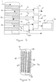
- the reactor system comprises a reactor having a shell comprising:one or more reactor tubes located within the shell, said reactor tube or tubes comprising a plurality of catalyst receptacles containing catalyst;means for providing a heat transfer fluid to the reactor shell such that the heat transfer fluid contacts the tube or tubes;an inlet for providing reactants to the reactor tubes; and an outlet for recovering products from the reactor tubes;
- the plurality of catalyst receptacles containing catalyst within a tube comprises catalyst receptacles containing catalyst of at least two configurations in that the catalyst receptacles containing catalyst differ in the type of catalyst within the receptacle, the amount of catalyst within the receptacle, the amount of heat removed from the receptacle or combinations of these;wherein the configurations of the catalyst receptacles are such that the temperature of the
- the manner in which the configuration of the receptacles differs is discussed in more detail below. However, the main ways in which they differ relate to the type of catalyst within the receptacle, the amount of catalyst within the receptacle, the amount of heat removed from the receptacle or combinations of these.
- the reaction can be optimised such that the catalyst temperature is maintained within a region where its performance is maximised and the reaction pathway plotted as conversion versus operating temperature most closely follows the locus of optimal reaction rate.
- the invention will allow the temperature of the reaction to be within 100°C of the optimum temperature at a given conversion level.
- each tube includes a series of adiabatic beds with intermediate cooling for an exothermic reaction, or heating where the reaction is endothermic.
- the reactor comprises a plurality of parallel systems each including a series of adiabatic beds.
- the number of catalyst receptacles located with the tube will depend on the reaction being carried out and the size of the reactor used. Thus there may be from about 10 to about 100 receptacles.
- each catalyst receptacle containing catalyst will be of a different configuration to each other within a respective tube.
- catalyst receptacles containing catalyst of the same configuration are grouped together such that there are sets of receptacles of the same configuration which may be repeated within the tube.
- reaction being carried out is the production of sulphur trioxide from sulphur dioxide
- any suitable catalyst receptacle may be used.
- the catalyst receptacle is that described in WO2011/048361 .
- the catalyst receptacle may be that disclosed in GB1417462.7 of 2nd October 2014 .
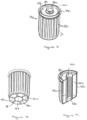
- the catalyst receptacle may comprise:
- the catalyst receptacle may comprise:
- the catalyst receptacle will generally be sized such that it is of a smaller dimension than the internal dimension of the reactor tube into which it is placed.
- the seal will be sized such that it interacts with the inner wall of the reactor tube when the catalyst receptacle of the present invention is in position within the reactor tube.
- reactant(s) In use in a vertical reactor with downflow, reactant(s) flow downwardly through the reactor tube and thus first contact the upper surface of the catalyst receptacle. Since the seal blocks the passage of the reactant(s) around the side of the receptacle, the top surface thereof directs them into the inner channel defined by the inner container wall. The reactant(s) then enters the annular container through the perforated inner container wall and then passes radially through the catalyst bed towards the perforated outer container wall. During the passage from the inner container wall to the outer container wall, the reactant(s) contact the catalyst and reaction occurs. Unreacted reactant and product then flow out of the container through the perforated outer container wall.
- the carrier outer wall then directs reactant and product upwardly between the inner surface of the carrier outer wall and the perforated outer container wall of the annular container until they reach the apertures in the carrier outer wall. They are then directed through the apertures located in the carrier outer wall and flow downwardly between the outer surface of the carrier outer wall and the inner surface of the reactor tube where heat transfer takes place. In the event that the reactor is operated such that the flow is reversed, the path will be reversed.
- the top surface of the container may be of any suitable size and configuration.
- the top surface will at least extend outwardly from the perforated outer container wall and will connect with the carrier outer wall.
- the top surface may extend from the perforated inner container wall to the carrier outer wall. It will be understood that the top surface may be an annulus which extends from a point between the location of the perforated inner container wall and the perforated outer container wall to the carrier outer wall.
- a cap may close the inner channel formed by the perforated inner container wall. This cap will include one or more apertures to allow for fluid flow into the inner channel.
- the size of the perforations in the inner container wall and the outer container wall will be selected such as to allow uniform flow of reactant(s) and product(s) through the catalyst while maintaining the catalyst within the container. It will therefore be understood that their size will depend on the size of the catalyst particles being used.
- the perforations may be sized such that they are larger but have a filter mesh covering the perforations to ensure catalyst is maintained within the annular container. This enables larger perforations to be used which will facilitate the free movement of reactants without a significant loss of pressure.
- perforations may be of any suitable configuration. Indeed where a wall is described as perforated all that is required is that there is means to allow the reactants and products to pass through the walls. These may be small apertures of any configuration, they may be slots, they may be formed by a wire screen, or by any other means of creating a porous or permeable surface.
- the top surface closing the container will generally be located at the upper edge of the inner container wall and/or the outer container wall, it may be desirable to locate the top surface below the upper edge such that a portion of the upper edge of the carrier outer wall extends above the top surface.
- the bottom surface may be located at the lower edge of the inner container wall and/or the outer container wall or it may be desirable to locate the bottom surface such that it is above the bottom edge of the outer container wall such that it extends below the bottom surface. Where the carrier outer wall extends above the top and/or the bottom surface, this may facilitate the stacking of containers against others. Additionally or alternatively, this configuration may be configured to facilitate connecting the catalyst receptacle to adjacent catalyst receptacles.
- the bottom surface of the annular container and the surface closing the bottom of the inner channel may be formed as a single unit or they may be two separate pieces connected together.
- the bottom surface of the annular container and the surface closing the bottom of the inner channel may be coplanar but in one arrangement, they are in different planes.
- the surface closing the bottom of the inner channel is in a lower plane than the bottom surface of the annular container. This may serve to assist in the location of one catalyst receptacle onto a catalyst receptacle arranged below it.
- the surface closing the bottom of the inner channel may be in a higher plane that the bottom surface of the annular container. This may assist in the location of one receptacle onto a receptacle arranged below it.
- the container is configured for holding a monolith catalyst.
- the monolith catalyst is a solid, in that there is substantially no space within the body of the monolith that is not occupied by catalyst.
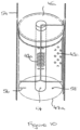
- the reactant(s) flow downwardly through the reactor tube, the reactant(s) first contacts the upper face of the monolith catalyst and flows therethrough in a direction parallel to the axis of the catalyst receptacle.
- the seal of the container prevents the reactant(s) from flowing around the monolith and assists the direction of the reactants into the catalyst. Reaction will then occur within the monolith catalyst.
- the product will then also flow down through the monolith in a direction parallel to the axis of the catalyst receptacle.
- the top surface will at least extend outwardly from the monolith catalyst and will connect with the carrier outer wall. It will be understood that the top surface may be an annulus which extends over at least a portion of the monolith catalyst to the carrier outer wall.
- the reactant(s) and product reach the bottom surface of the container they are directed towards the carrier outer wall.
- feet may be provided within the container on the upper face of the bottom surface such that, in use, the catalyst monolith is supported on the feet and there is a gap between the bottom of the catalyst monolith and the bottom surface of the container.
- the carrier outer wall directs the reactant(s) and product upwardly between the inner surface of the carrier outer wall and the outer surface of the monolith catalyst until they reach the underside of the top surface. They are then directed by the underside of the top surface, through the apertures in the carrier outer wall and they then flow downwardly between the outer surface of the carrier outer wall and the inner surface of the reactor tube where heat transfer takes place.
- the monolith catalyst has a channel extending longitudinally therethrough. Generally the channel will be located on the central axis of the monolith catalyst.
- the monolith catalyst of this arrangement will be of annular cross-section.
- reactant(s) flow downwardly through the reactor tube and thus first contacts the upper surface of the top surface of the container and are directed into the channel of the monolith.
- the reactant(s) then enters the annular monolith catalyst and passes radially through the catalyst towards the outer surface of the catalyst monolith. During the passage through the catalyst monolith reaction occurs. Unreacted reactant and product then flow out of the monolith catalyst though the outer surface thereof.
- the carrier outer wall then directs reactant and product upwardly between the inner surface of the carrier outer wall and the outer surface of the monolith catalyst until they reach the top surface. They are then directed, by the underside of the top surface, through the apertures in the carrier outer wall and flow downwardly between the outer surface of the carrier outer wall and the inner surface of the reactor tube where heat transfer takes place.
- the top surface may extend over the monolith catalyst but leave the channel uncovered. In another arrangement, the top surface may extend across the channel but will include apertures in this region to allow for fluid flow.
- the adiabatic temperature rise per catalyst receptacle will be related to the conversion performed per catalyst receptacle and the amount of conversion will be related to the amount of catalyst held in the catalyst receptacle.
- the reactor tubes are loaded with identical catalyst receptacles.
- the selection of the design of the receptacle has to be a compromise between ensuring sufficient reaction takes place to achieve the desired conversion whilst ensuring that the discharge temperature from the tubular reactor is sufficiently low to meet the equilibrium temperature that determines the overall conversion of SO 2 to SO 3 .
- the average deviation of the absolute values of the inlet/exit temperatures (on an absolute basis) from the optimum value relevant to the conversion at that point in the reactor is 90°C.
- the diagonal lines which show the operating temperature versus the conversion could be +/- 90°C. Again the maximum temperature for a given conversion will be limited by the equilibrium temperature and the difference between MRL and equilibrium temperature may be lower than 90°C, so depending on position in the reactor the temperature deviation may be +30°C/-120°C for example.
- Example 2 is similar to Comparative Example 1 except that the reactor contains several zones of catalyst receptacles, the design of receptacle in each zone is optimised to ensure that the temperature rise per catalyst bed and the temperature drop achieved during the heat transfer to the shell-side of the reactor are such that the catalyst volume required is optimised by ensuring that the catalyst operates as close to the optimum temperature as possible.
Landscapes
- Chemical & Material Sciences (AREA)
- Organic Chemistry (AREA)
- Chemical Kinetics & Catalysis (AREA)
- Inorganic Chemistry (AREA)
- Physics & Mathematics (AREA)
- Fluid Mechanics (AREA)
- Devices And Processes Conducted In The Presence Of Fluids And Solid Particles (AREA)
- Physical Or Chemical Processes And Apparatus (AREA)
Claims (13)
- Procédé permettant d'effectuer une réaction limitée par équilibre, le procédé comprenant la fourniture de réactifs à un système de réacteur, le fait de laisser la réaction se produire et la récupération d'un produit, dans lequel le système de réacteur comprend un réacteur ayant une enveloppe (30) comprenant :un ou plusieurs tubes de réacteur (33) localisés au sein de l'enveloppe (30), ledit tube ou lesdits tubes de réacteur (33) comprenant une pluralité de réceptacles à catalyseur (34, 34a) contenant un catalyseur ;un moyen permettant de fournir un fluide de transfert de chaleur (35) à l'enveloppe de réacteur (30) de telle sorte que le fluide de transfert de chaleur (35) vient en contact avec le tube ou les tubes (33) ;une entrée (31) permettant de fournir des réactifs aux tubes de réacteur (33) ; etune sortie (32) permettant de récupérer des produits dans les tubes de réacteur (33) ;dans lequel la pluralité de réceptacles à catalyseur (34, 34a) contenant un catalyseur au sein d'un tube (33) comprend des réceptacles à catalyseur (34, 34a) contenant un catalyseur d'au moins deux configurations en ce que les réceptacles à catalyseur (34, 34a) contenant un catalyseur diffèrent dans le type de catalyseur au sein du réceptacle, la quantité de catalyseur au sein du réceptacle, la quantité de chaleur retirée du réceptacle ou des combinaisons de celles-ci ;dans lequel les configurations des réceptacles à catalyseur (34, 34a) sont telles que la température de la réaction est à moins de 100 °C du lieu de vitesse maximale de la vitesse maximale de réaction par rapport au produit en fonction de la conversion.
- Procédé selon la revendication 1, dans lequel il y a trois, quatre, cinq, six, sept, huit, neuf ou dix configurations différentes de réceptacles à catalyseur (34, 34a) contenant un catalyseur.
- Procédé selon la revendication 1 ou la revendication 2 dans lequel le réceptacle à catalyseur (34, 34a) comprend :un récipient (41) comprenant un catalyseur, ledit récipient ayant une surface inférieure (47) fermant le récipient, et une surface supérieure (45) ;une paroi externe de support (53) s'étendant à partir de la surface inférieure (47) dudit récipient jusqu'à la surface supérieure (45) ;un joint d'étanchéité (49) s'étendant à partir du récipient (41) sur une distance qui s'étend au-delà de la paroi externe de support (53) ;ladite paroi externe de support (53) ayant des ouvertures (55) localisées en dessous du joint d'étanchéité (49).
- Procédé selon la revendication 1 ou la revendication 2 dans lequel le réceptacle à catalyseur (34, 34a) comprend :un récipient annulaire (41), ledit récipient ayant une paroi de récipient interne (42) perforée définissant un canal interne (44), une paroi de récipient externe (43) perforée, une surface supérieure (45) fermant le récipient annulaire (41) et une surface inférieure (47) fermant le récipient annulaire (41) ;une surface (48) fermant le fond dudit canal interne (44) formé par la paroi de récipient interne (42) du récipient annulaire (41).
- Procédé selon l'une quelconque des revendications 1 à 4 dans lequel les au moins deux configurations de réceptacles à catalyseur (34, 34a) contenant un catalyseur comprennent l'utilisation de catalyseurs différents.
- Procédé selon l'une quelconque des revendications 1 à 5 dans lequel les au moins deux configurations de réceptacles à catalyseur (34, 34a) comprennent un changement dans la quantité de catalyseur chargé dans le réceptacle à catalyseur.
- Procédé selon la revendication 6 dans lequel le changement dans la quantité de catalyseur chargé dans le support de catalyseur est obtenu en modifiant la quantité de catalyseur chargé dans le réceptacle à catalyseur (34, 34a) et en remplissant le réceptacle avec un matériau inerte.
- Procédé selon la revendication 6 dans lequel le changement dans la quantité de catalyseur chargé dans le réceptacle à catalyseur (34, 34a) est obtenu en modifiant la longueur du réceptacle.
- Procédé selon l'une quelconque des revendications 1 à 8 dans lequel les au moins deux configurations de réceptacles à catalyseur (34, 34a) comprennent une modification du diamètre du support de telle sorte que lorsqu'il est chargé dans un tube (33), l'espace annulaire entre le réceptacle à catalyseur (34, 34a) et le tube à réaction (33) dans lequel il doit être inséré est modifié.
- Procédé selon l'une quelconque des revendications 1 à 9 dans lequel le système de réacteur comprend en outre un ou plusieurs lits adiabatiques classiques utilisés en combinaison avec le réacteur.
- Procédé selon la revendication 10 dans lequel le système de réacteur est configuré de telle sorte qu'une réaction en masse peut être effectuée initialement dans un lit adiabatique classique avant d'être passée au réacteur.
- Procédé selon l'une quelconque des revendications 1 à 11 dans lequel le procédé est l'oxydation de dioxyde de soufre en trioxyde de soufre, la fabrication d'ammoniac, la synthèse de méthanol à partir de monoxyde de carbone et d'hydrogène, la réaction de conversion eau-gaz, la réaction inverse de conversion eau-gaz, la fabrication de styrène, la déshydratation d'éthylbenzène, la déshydrogénation d'alcanes, des réactions de méthanation, ou un reformage de méthane à la vapeur.
- Procédé selon l'une quelconque des revendications 1 à 12 dans lequel la réaction étant effectuée est l'oxydation de dioxyde de soufre pour produire du trioxyde de soufre, la pression de fonctionnement sera généralement appliquée à une pression d'entrée d'environ 1,4 bar (absolu), une conversion initiale ayant lieu à une température d'environ 600 °C à environ 700 °C et, à mesure que la conversion progresse, la température diminue à environ 380 °C à environ 420 °C.
Applications Claiming Priority (3)
| Application Number | Priority Date | Filing Date | Title |
|---|---|---|---|
| GBGB1506572.5A GB201506572D0 (en) | 2015-04-17 | 2015-04-17 | Process |
| EP16715037.4A EP3283210B1 (fr) | 2015-04-17 | 2016-03-24 | Procédé |
| PCT/GB2016/050858 WO2016166507A1 (fr) | 2015-04-17 | 2016-03-24 | Procédé |
Related Parent Applications (2)
| Application Number | Title | Priority Date | Filing Date |
|---|---|---|---|
| EP16715037.4A Division EP3283210B1 (fr) | 2015-04-17 | 2016-03-24 | Procédé |
| EP16715037.4A Division-Into EP3283210B1 (fr) | 2015-04-17 | 2016-03-24 | Procédé |
Publications (2)
| Publication Number | Publication Date |
|---|---|
| EP3922346A1 EP3922346A1 (fr) | 2021-12-15 |
| EP3922346B1 true EP3922346B1 (fr) | 2025-06-25 |
Family
ID=53298770
Family Applications (2)
| Application Number | Title | Priority Date | Filing Date |
|---|---|---|---|
| EP16715037.4A Active EP3283210B1 (fr) | 2015-04-17 | 2016-03-24 | Procédé |
| EP21189504.0A Active EP3922346B1 (fr) | 2015-04-17 | 2016-03-24 | Réacteur avec receptacles pour catalyseurs et procédé utilisant celui-ci |
Family Applications Before (1)
| Application Number | Title | Priority Date | Filing Date |
|---|---|---|---|
| EP16715037.4A Active EP3283210B1 (fr) | 2015-04-17 | 2016-03-24 | Procédé |
Country Status (16)
| Country | Link |
|---|---|
| US (3) | US10683206B2 (fr) |
| EP (2) | EP3283210B1 (fr) |
| KR (1) | KR102543016B1 (fr) |
| CN (2) | CN107666955B (fr) |
| BR (1) | BR112017022174B1 (fr) |
| CA (1) | CA2982688C (fr) |
| DK (2) | DK3283210T3 (fr) |
| EA (1) | EA036841B1 (fr) |
| ES (2) | ES2898859T3 (fr) |
| FI (1) | FI3922346T3 (fr) |
| GB (2) | GB201506572D0 (fr) |
| HU (2) | HUE057118T2 (fr) |
| PT (2) | PT3283210T (fr) |
| TW (1) | TWI698280B (fr) |
| WO (1) | WO2016166507A1 (fr) |
| ZA (1) | ZA201706799B (fr) |
Families Citing this family (11)
| Publication number | Priority date | Publication date | Assignee | Title |
|---|---|---|---|---|
| US9958211B2 (en) | 2015-03-12 | 2018-05-01 | Bayotech, Inc. | Nested-flow heat exchangers and chemical reactors |
| GB202015186D0 (en) * | 2020-09-25 | 2020-11-11 | Johnson Matthey Davy Technologies Ltd | Improvements in or relating to catalyst carriers for tubular reactors and associated methods |
| US11994061B2 (en) | 2021-05-14 | 2024-05-28 | Amogy Inc. | Methods for reforming ammonia |
| US11724245B2 (en) | 2021-08-13 | 2023-08-15 | Amogy Inc. | Integrated heat exchanger reactors for renewable fuel delivery systems |
| KR20240017375A (ko) * | 2021-06-03 | 2024-02-07 | 토프쉐 에이/에스 | 금속 더스팅이 감소된 열교환 반응기 |
| JP2024521417A (ja) | 2021-06-11 | 2024-05-31 | アモジー インコーポレイテッド | アンモニアを処理するためのシステムおよび方法 |
| US11539063B1 (en) | 2021-08-17 | 2022-12-27 | Amogy Inc. | Systems and methods for processing hydrogen |
| MA71239A (fr) * | 2022-06-24 | 2025-04-30 | Topsoe A/S | Production d'ammoniac à partir de gaz de synthèse se caractérisant par une grande variété de charges d'alimentation d'installation |
| US11834334B1 (en) | 2022-10-06 | 2023-12-05 | Amogy Inc. | Systems and methods of processing ammonia |
| US11866328B1 (en) | 2022-10-21 | 2024-01-09 | Amogy Inc. | Systems and methods for processing ammonia |
| US11795055B1 (en) | 2022-10-21 | 2023-10-24 | Amogy Inc. | Systems and methods for processing ammonia |
Family Cites Families (18)
| Publication number | Priority date | Publication date | Assignee | Title |
|---|---|---|---|---|
| US1945811A (en) * | 1930-02-20 | 1934-02-06 | Selden Co | Contact sulphuric acid process |
| US2331427A (en) * | 1939-06-28 | 1943-10-12 | Phillips Petroleum Co | Control of catalytic reactions |
| NL62754C (fr) * | 1941-01-27 | |||
| US2353509A (en) * | 1942-02-06 | 1944-07-11 | Phillips Petroleum Co | Process for hydrocarbon conversion |
| JPS5118955B2 (fr) | 1972-04-12 | 1976-06-14 | ||
| DE3880877T2 (de) * | 1987-02-26 | 1993-09-23 | Ammonia Casale Sa | System zur verbesserung der reaktorausbeute fuer exotherme synthese, insbesondere fuer die ammoniakreaktion. |
| JP2526404B2 (ja) * | 1993-10-15 | 1996-08-21 | 工業技術院長 | 触媒反応方法 |
| EP1080778B1 (fr) * | 1999-08-31 | 2003-07-23 | Ammonia Casale S.A. | Procédé de modernisation in-situ d'un réacteur pour des synthèses hétérogènes |
| GB0113078D0 (en) * | 2001-05-30 | 2001-07-18 | Kvaerner Process Tech Ltd | Process and plant |
| KR100553825B1 (ko) * | 2003-09-01 | 2006-02-21 | 주식회사 엘지화학 | 고정층 촉매 부분 산화 반응기에서 개선된 제열 시스템을통한 불포화알데히드 및 불포화산의 제조 방법 |
| TWI349001B (en) * | 2005-03-18 | 2011-09-21 | Lg Chemical Ltd | Method of producing unsaturated acid from olefin |
| DE102007006647A1 (de) | 2007-02-06 | 2008-08-07 | Basf Se | Verfahren zur Regenerierung eines im Rahmen einer heterogen katalysierten partiellen Dehydrierung eines Kohlenwasserstoffs deaktivierten Katalysatorbetts |
| GB0918246D0 (en) * | 2009-10-19 | 2009-12-02 | Davy Process Techn Ltd | Apparatus |
| GB201105691D0 (en) | 2011-04-04 | 2011-05-18 | Davy Process Techn Ltd | Apparatus |
| GB201107072D0 (en) * | 2011-04-27 | 2011-06-08 | Davy Process Techn Ltd | Process |
| GB201107070D0 (en) * | 2011-04-27 | 2011-06-08 | Davy Process Techn Ltd | FT process using can reactor |
| GB201401518D0 (en) | 2014-01-29 | 2014-03-12 | Johnson Matthey Davy Technologies Ltd | Apparatus & process |
| GB201403787D0 (en) | 2014-03-04 | 2014-04-16 | Johnson Matthey Plc | Steam reforming |
-
2015
- 2015-04-17 GB GBGB1506572.5A patent/GB201506572D0/en not_active Ceased
-
2016
- 2016-03-24 EP EP16715037.4A patent/EP3283210B1/fr active Active
- 2016-03-24 EP EP21189504.0A patent/EP3922346B1/fr active Active
- 2016-03-24 GB GB201605088A patent/GB2539991B/en active Active
- 2016-03-24 FI FIEP21189504.0T patent/FI3922346T3/fi active
- 2016-03-24 ES ES16715037T patent/ES2898859T3/es active Active
- 2016-03-24 CN CN201680030053.5A patent/CN107666955B/zh active Active
- 2016-03-24 PT PT167150374T patent/PT3283210T/pt unknown
- 2016-03-24 PT PT211895040T patent/PT3922346T/pt unknown
- 2016-03-24 BR BR112017022174-8A patent/BR112017022174B1/pt active IP Right Grant
- 2016-03-24 HU HUE16715037A patent/HUE057118T2/hu unknown
- 2016-03-24 DK DK16715037.4T patent/DK3283210T3/da active
- 2016-03-24 ES ES21189504T patent/ES3039672T3/es active Active
- 2016-03-24 CA CA2982688A patent/CA2982688C/fr active Active
- 2016-03-24 DK DK21189504.0T patent/DK3922346T3/da active
- 2016-03-24 KR KR1020177032892A patent/KR102543016B1/ko active Active
- 2016-03-24 EA EA201792299A patent/EA036841B1/ru not_active IP Right Cessation
- 2016-03-24 WO PCT/GB2016/050858 patent/WO2016166507A1/fr not_active Ceased
- 2016-03-24 HU HUE21189504A patent/HUE073408T2/hu unknown
- 2016-03-24 US US15/566,471 patent/US10683206B2/en active Active
- 2016-03-24 CN CN202210829690.6A patent/CN115282883B/zh active Active
- 2016-04-15 TW TW105111926A patent/TWI698280B/zh not_active IP Right Cessation
-
2017
- 2017-10-09 ZA ZA2017/06799A patent/ZA201706799B/en unknown
-
2020
- 2020-05-28 US US16/886,202 patent/US11161739B2/en active Active
-
2021
- 2021-10-14 US US17/501,322 patent/US11560309B2/en active Active
Also Published As
Similar Documents
| Publication | Publication Date | Title |
|---|---|---|
| US11560309B2 (en) | Process and reactor comprising a plurality of catalyst receptacles | |
| US10654018B2 (en) | Annular catalyst carrier container for use in a tubular reactor | |
| AU2012211334B2 (en) | Monolithic reactor | |
| US8722747B2 (en) | Vessel for containing catalyst in a tubular reactor | |
| CA1121987A (fr) | Appareil pour effectuer des reactions gazeuses exothermiques et endothermiques a haute pression, et methode pour ce faire | |
| EP2531290B1 (fr) | Procédé fischer-tropsch dans un réacteur radial | |
| Mazidi et al. | Optimization of Fischer‐Tropsch process in a fixed‐bed reactor using non‐uniform catalysts | |
| US8937190B2 (en) | Process for the production of anhydrides |
Legal Events
| Date | Code | Title | Description |
|---|---|---|---|
| PUAI | Public reference made under article 153(3) epc to a published international application that has entered the european phase |
Free format text: ORIGINAL CODE: 0009012 |
|
| STAA | Information on the status of an ep patent application or granted ep patent |
Free format text: STATUS: THE APPLICATION HAS BEEN PUBLISHED |
|
| AC | Divisional application: reference to earlier application |
Ref document number: 3283210 Country of ref document: EP Kind code of ref document: P |
|
| AK | Designated contracting states |
Kind code of ref document: A1 Designated state(s): AL AT BE BG CH CY CZ DE DK EE ES FI FR GB GR HR HU IE IS IT LI LT LU LV MC MK MT NL NO PL PT RO RS SE SI SK SM TR |
|
| B565 | Issuance of search results under rule 164(2) epc |
Effective date: 20211015 |
|
| STAA | Information on the status of an ep patent application or granted ep patent |
Free format text: STATUS: REQUEST FOR EXAMINATION WAS MADE |
|
| 17P | Request for examination filed |
Effective date: 20220614 |
|
| RBV | Designated contracting states (corrected) |
Designated state(s): AL AT BE BG CH CY CZ DE DK EE ES FI FR GB GR HR HU IE IS IT LI LT LU LV MC MK MT NL NO PL PT RO RS SE SI SK SM TR |
|
| P01 | Opt-out of the competence of the unified patent court (upc) registered |
Effective date: 20230526 |
|
| GRAP | Despatch of communication of intention to grant a patent |
Free format text: ORIGINAL CODE: EPIDOSNIGR1 |
|
| STAA | Information on the status of an ep patent application or granted ep patent |
Free format text: STATUS: GRANT OF PATENT IS INTENDED |
|
| RIC1 | Information provided on ipc code assigned before grant |
Ipc: C01B 17/74 20060101ALI20250121BHEP Ipc: B01J 8/04 20060101ALI20250121BHEP Ipc: B01J 8/02 20060101ALI20250121BHEP Ipc: B01J 19/24 20060101ALI20250121BHEP Ipc: B01J 8/06 20060101AFI20250121BHEP |
|
| INTG | Intention to grant announced |
Effective date: 20250207 |
|
| RAP3 | Party data changed (applicant data changed or rights of an application transferred) |
Owner name: JOHNSON MATTHEY DAVY TECHNOLOGIES LIMITED |
|
| GRAS | Grant fee paid |
Free format text: ORIGINAL CODE: EPIDOSNIGR3 |
|
| GRAA | (expected) grant |
Free format text: ORIGINAL CODE: 0009210 |
|
| STAA | Information on the status of an ep patent application or granted ep patent |
Free format text: STATUS: THE PATENT HAS BEEN GRANTED |
|
| AC | Divisional application: reference to earlier application |
Ref document number: 3283210 Country of ref document: EP Kind code of ref document: P |
|
| AK | Designated contracting states |
Kind code of ref document: B1 Designated state(s): AL AT BE BG CH CY CZ DE DK EE ES FI FR GB GR HR HU IE IS IT LI LT LU LV MC MK MT NL NO PL PT RO RS SE SI SK SM TR |
|
| REG | Reference to a national code |
Ref country code: GB Ref legal event code: FG4D |
|
| REG | Reference to a national code |
Ref country code: CH Ref legal event code: EP |
|
| REG | Reference to a national code |
Ref country code: CH Ref legal event code: EP |
|
| REG | Reference to a national code |
Ref country code: IE Ref legal event code: FG4D |
|
| REG | Reference to a national code |
Ref country code: DE Ref legal event code: R096 Ref document number: 602016092716 Country of ref document: DE |
|
| REG | Reference to a national code |
Ref country code: FI Ref legal event code: FGE |
|
| REG | Reference to a national code |
Ref country code: DK Ref legal event code: T3 Effective date: 20250808 |
|
| REG | Reference to a national code |
Ref country code: SE Ref legal event code: TRGR |
|
| REG | Reference to a national code |
Ref country code: NL Ref legal event code: FP |
|
| REG | Reference to a national code |
Ref country code: PT Ref legal event code: SC4A Ref document number: 3922346 Country of ref document: PT Date of ref document: 20250908 Kind code of ref document: T Free format text: AVAILABILITY OF NATIONAL TRANSLATION Effective date: 20250901 |
|
| REG | Reference to a national code |
Ref country code: LT Ref legal event code: MG9D |
|
| PG25 | Lapsed in a contracting state [announced via postgrant information from national office to epo] |
Ref country code: GR Free format text: LAPSE BECAUSE OF FAILURE TO SUBMIT A TRANSLATION OF THE DESCRIPTION OR TO PAY THE FEE WITHIN THE PRESCRIBED TIME-LIMIT Effective date: 20250926 |
|
| PG25 | Lapsed in a contracting state [announced via postgrant information from national office to epo] |
Ref country code: BG Free format text: LAPSE BECAUSE OF FAILURE TO SUBMIT A TRANSLATION OF THE DESCRIPTION OR TO PAY THE FEE WITHIN THE PRESCRIBED TIME-LIMIT Effective date: 20250625 |
|
| PG25 | Lapsed in a contracting state [announced via postgrant information from national office to epo] |
Ref country code: HR Free format text: LAPSE BECAUSE OF FAILURE TO SUBMIT A TRANSLATION OF THE DESCRIPTION OR TO PAY THE FEE WITHIN THE PRESCRIBED TIME-LIMIT Effective date: 20250625 |
|
| PG25 | Lapsed in a contracting state [announced via postgrant information from national office to epo] |
Ref country code: RS Free format text: LAPSE BECAUSE OF FAILURE TO SUBMIT A TRANSLATION OF THE DESCRIPTION OR TO PAY THE FEE WITHIN THE PRESCRIBED TIME-LIMIT Effective date: 20250925 |
|
| REG | Reference to a national code |
Ref country code: ES Ref legal event code: FG2A Ref document number: 3039672 Country of ref document: ES Kind code of ref document: T3 Effective date: 20251023 |
|
| PG25 | Lapsed in a contracting state [announced via postgrant information from national office to epo] |
Ref country code: LV Free format text: LAPSE BECAUSE OF FAILURE TO SUBMIT A TRANSLATION OF THE DESCRIPTION OR TO PAY THE FEE WITHIN THE PRESCRIBED TIME-LIMIT Effective date: 20250625 |
|
| PG25 | Lapsed in a contracting state [announced via postgrant information from national office to epo] |
Ref country code: IS Free format text: LAPSE BECAUSE OF FAILURE TO SUBMIT A TRANSLATION OF THE DESCRIPTION OR TO PAY THE FEE WITHIN THE PRESCRIBED TIME-LIMIT Effective date: 20251025 |
|
| PG25 | Lapsed in a contracting state [announced via postgrant information from national office to epo] |
Ref country code: SM Free format text: LAPSE BECAUSE OF FAILURE TO SUBMIT A TRANSLATION OF THE DESCRIPTION OR TO PAY THE FEE WITHIN THE PRESCRIBED TIME-LIMIT Effective date: 20250625 |
|
| PG25 | Lapsed in a contracting state [announced via postgrant information from national office to epo] |
Ref country code: CZ Free format text: LAPSE BECAUSE OF FAILURE TO SUBMIT A TRANSLATION OF THE DESCRIPTION OR TO PAY THE FEE WITHIN THE PRESCRIBED TIME-LIMIT Effective date: 20250625 |
|
| PG25 | Lapsed in a contracting state [announced via postgrant information from national office to epo] |
Ref country code: PL Free format text: LAPSE BECAUSE OF FAILURE TO SUBMIT A TRANSLATION OF THE DESCRIPTION OR TO PAY THE FEE WITHIN THE PRESCRIBED TIME-LIMIT Effective date: 20250625 |
|
| PG25 | Lapsed in a contracting state [announced via postgrant information from national office to epo] |
Ref country code: EE Free format text: LAPSE BECAUSE OF FAILURE TO SUBMIT A TRANSLATION OF THE DESCRIPTION OR TO PAY THE FEE WITHIN THE PRESCRIBED TIME-LIMIT Effective date: 20250625 |
|
| PG25 | Lapsed in a contracting state [announced via postgrant information from national office to epo] |
Ref country code: SK Free format text: LAPSE BECAUSE OF FAILURE TO SUBMIT A TRANSLATION OF THE DESCRIPTION OR TO PAY THE FEE WITHIN THE PRESCRIBED TIME-LIMIT Effective date: 20250625 |
|
| REG | Reference to a national code |
Ref country code: HU Ref legal event code: AG4A Ref document number: E073408 Country of ref document: HU |
|
| PGFP | Annual fee paid to national office [announced via postgrant information from national office to epo] |
Ref country code: NL Payment date: 20260219 Year of fee payment: 11 |
|
| PGFP | Annual fee paid to national office [announced via postgrant information from national office to epo] |
Ref country code: SE Payment date: 20260219 Year of fee payment: 11 |
|
| PGFP | Annual fee paid to national office [announced via postgrant information from national office to epo] |
Ref country code: GB Payment date: 20260220 Year of fee payment: 11 |
|
| PGFP | Annual fee paid to national office [announced via postgrant information from national office to epo] |
Ref country code: DK Payment date: 20260219 Year of fee payment: 11 Ref country code: NO Payment date: 20260223 Year of fee payment: 11 Ref country code: DE Payment date: 20260219 Year of fee payment: 11 |
|
| PGFP | Annual fee paid to national office [announced via postgrant information from national office to epo] |
Ref country code: AT Payment date: 20260223 Year of fee payment: 11 |
|
| PGFP | Annual fee paid to national office [announced via postgrant information from national office to epo] |
Ref country code: FI Payment date: 20260219 Year of fee payment: 11 Ref country code: IT Payment date: 20260219 Year of fee payment: 11 |
|
| PGFP | Annual fee paid to national office [announced via postgrant information from national office to epo] |
Ref country code: HU Payment date: 20260313 Year of fee payment: 11 |
|
| PGFP | Annual fee paid to national office [announced via postgrant information from national office to epo] |
Ref country code: FR Payment date: 20260219 Year of fee payment: 11 |
|
| PGFP | Annual fee paid to national office [announced via postgrant information from national office to epo] |
Ref country code: PT Payment date: 20260220 Year of fee payment: 11 |
|
| PLBE | No opposition filed within time limit |
Free format text: ORIGINAL CODE: 0009261 |
|
| STAA | Information on the status of an ep patent application or granted ep patent |
Free format text: STATUS: NO OPPOSITION FILED WITHIN TIME LIMIT |