EP3922385A1 - Procédé de séparation d'une pluralité de disques à partir de pièces au moyen d'une scie à fil lors d'une séquence de processus de séparation - Google Patents
Procédé de séparation d'une pluralité de disques à partir de pièces au moyen d'une scie à fil lors d'une séquence de processus de séparation Download PDFInfo
- Publication number
- EP3922385A1 EP3922385A1 EP20179134.0A EP20179134A EP3922385A1 EP 3922385 A1 EP3922385 A1 EP 3922385A1 EP 20179134 A EP20179134 A EP 20179134A EP 3922385 A1 EP3922385 A1 EP 3922385A1
- Authority
- EP
- European Patent Office
- Prior art keywords
- wire
- workpiece
- profile
- cutting
- processes
- Prior art date
- Legal status (The legal status is an assumption and is not a legal conclusion. Google has not performed a legal analysis and makes no representation as to the accuracy of the status listed.)
- Pending
Links
- 238000000034 method Methods 0.000 title claims abstract description 36
- 238000000926 separation method Methods 0.000 title claims abstract description 18
- 238000006073 displacement reaction Methods 0.000 claims abstract description 45
- 238000012937 correction Methods 0.000 claims abstract description 40
- 238000005520 cutting process Methods 0.000 claims abstract description 39
- 230000008569 process Effects 0.000 claims abstract description 15
- 239000000110 cooling liquid Substances 0.000 claims abstract description 12
- 239000000463 material Substances 0.000 claims abstract description 9
- 239000012530 fluid Substances 0.000 claims abstract description 8
- 230000000694 effects Effects 0.000 claims abstract description 7
- 238000005496 tempering Methods 0.000 claims abstract description 4
- 238000012935 Averaging Methods 0.000 claims description 5
- 235000012431 wafers Nutrition 0.000 claims description 5
- 238000012423 maintenance Methods 0.000 claims description 3
- 230000008859 change Effects 0.000 description 8
- 230000008901 benefit Effects 0.000 description 4
- 230000001419 dependent effect Effects 0.000 description 4
- 238000012545 processing Methods 0.000 description 4
- 239000007788 liquid Substances 0.000 description 3
- 239000004065 semiconductor Substances 0.000 description 3
- 230000006978 adaptation Effects 0.000 description 2
- 230000003993 interaction Effects 0.000 description 2
- 238000005259 measurement Methods 0.000 description 2
- 230000005855 radiation Effects 0.000 description 2
- 239000000126 substance Substances 0.000 description 2
- 238000013459 approach Methods 0.000 description 1
- 239000011248 coating agent Substances 0.000 description 1
- 238000000576 coating method Methods 0.000 description 1
- 230000008602 contraction Effects 0.000 description 1
- 239000005068 cooling lubricant Substances 0.000 description 1
- 230000006866 deterioration Effects 0.000 description 1
- 229910003460 diamond Inorganic materials 0.000 description 1
- 239000010432 diamond Substances 0.000 description 1
- 230000007717 exclusion Effects 0.000 description 1
- 230000001939 inductive effect Effects 0.000 description 1
- 238000012986 modification Methods 0.000 description 1
- 230000004048 modification Effects 0.000 description 1
- 229910021421 monocrystalline silicon Inorganic materials 0.000 description 1
- 230000003287 optical effect Effects 0.000 description 1
- 230000035484 reaction time Effects 0.000 description 1
- 230000004044 response Effects 0.000 description 1
- 229910052710 silicon Inorganic materials 0.000 description 1
- 239000010703 silicon Substances 0.000 description 1
- 239000002002 slurry Substances 0.000 description 1
Images




Classifications
-
- B—PERFORMING OPERATIONS; TRANSPORTING
- B23—MACHINE TOOLS; METAL-WORKING NOT OTHERWISE PROVIDED FOR
- B23D—PLANING; SLOTTING; SHEARING; BROACHING; SAWING; FILING; SCRAPING; LIKE OPERATIONS FOR WORKING METAL BY REMOVING MATERIAL, NOT OTHERWISE PROVIDED FOR
- B23D57/00—Sawing machines or sawing devices not covered by one of the preceding groups B23D45/00 - B23D55/00
- B23D57/0007—Sawing machines or sawing devices not covered by one of the preceding groups B23D45/00 - B23D55/00 using saw wires
- B23D57/0023—Sawing machines or sawing devices not covered by one of the preceding groups B23D45/00 - B23D55/00 using saw wires with a plurality of saw wires or saw wires having plural cutting zones
-
- B—PERFORMING OPERATIONS; TRANSPORTING
- B23—MACHINE TOOLS; METAL-WORKING NOT OTHERWISE PROVIDED FOR
- B23D—PLANING; SLOTTING; SHEARING; BROACHING; SAWING; FILING; SCRAPING; LIKE OPERATIONS FOR WORKING METAL BY REMOVING MATERIAL, NOT OTHERWISE PROVIDED FOR
- B23D57/00—Sawing machines or sawing devices not covered by one of the preceding groups B23D45/00 - B23D55/00
- B23D57/003—Sawing machines or sawing devices working with saw wires, characterised only by constructional features of particular parts
- B23D57/0053—Sawing machines or sawing devices working with saw wires, characterised only by constructional features of particular parts of drives for saw wires; of wheel mountings; of wheels
-
- B—PERFORMING OPERATIONS; TRANSPORTING
- B23—MACHINE TOOLS; METAL-WORKING NOT OTHERWISE PROVIDED FOR
- B23D—PLANING; SLOTTING; SHEARING; BROACHING; SAWING; FILING; SCRAPING; LIKE OPERATIONS FOR WORKING METAL BY REMOVING MATERIAL, NOT OTHERWISE PROVIDED FOR
- B23D59/00—Accessories specially designed for sawing machines or sawing devices
- B23D59/001—Measuring or control devices, e.g. for automatic control of work feed pressure on band saw blade
-
- B—PERFORMING OPERATIONS; TRANSPORTING
- B23—MACHINE TOOLS; METAL-WORKING NOT OTHERWISE PROVIDED FOR
- B23D—PLANING; SLOTTING; SHEARING; BROACHING; SAWING; FILING; SCRAPING; LIKE OPERATIONS FOR WORKING METAL BY REMOVING MATERIAL, NOT OTHERWISE PROVIDED FOR
- B23D59/00—Accessories specially designed for sawing machines or sawing devices
- B23D59/001—Measuring or control devices, e.g. for automatic control of work feed pressure on band saw blade
- B23D59/002—Measuring or control devices, e.g. for automatic control of work feed pressure on band saw blade for the position of the saw blade
-
- B—PERFORMING OPERATIONS; TRANSPORTING
- B23—MACHINE TOOLS; METAL-WORKING NOT OTHERWISE PROVIDED FOR
- B23D—PLANING; SLOTTING; SHEARING; BROACHING; SAWING; FILING; SCRAPING; LIKE OPERATIONS FOR WORKING METAL BY REMOVING MATERIAL, NOT OTHERWISE PROVIDED FOR
- B23D59/00—Accessories specially designed for sawing machines or sawing devices
- B23D59/04—Devices for lubricating or cooling straight or strap saw blades
-
- B—PERFORMING OPERATIONS; TRANSPORTING
- B28—WORKING CEMENT, CLAY, OR STONE
- B28D—WORKING STONE OR STONE-LIKE MATERIALS
- B28D5/00—Fine working of gems, jewels, crystals, e.g. of semiconductor material; apparatus or devices therefor
- B28D5/0058—Accessories specially adapted for use with machines for fine working of gems, jewels, crystals, e.g. of semiconductor material
- B28D5/0064—Devices for the automatic drive or the program control of the machines
-
- B—PERFORMING OPERATIONS; TRANSPORTING
- B28—WORKING CEMENT, CLAY, OR STONE
- B28D—WORKING STONE OR STONE-LIKE MATERIALS
- B28D5/00—Fine working of gems, jewels, crystals, e.g. of semiconductor material; apparatus or devices therefor
- B28D5/0058—Accessories specially adapted for use with machines for fine working of gems, jewels, crystals, e.g. of semiconductor material
- B28D5/0076—Accessories specially adapted for use with machines for fine working of gems, jewels, crystals, e.g. of semiconductor material for removing dust, e.g. by spraying liquids; for lubricating, cooling or cleaning tool or work
-
- B—PERFORMING OPERATIONS; TRANSPORTING
- B28—WORKING CEMENT, CLAY, OR STONE
- B28D—WORKING STONE OR STONE-LIKE MATERIALS
- B28D5/00—Fine working of gems, jewels, crystals, e.g. of semiconductor material; apparatus or devices therefor
- B28D5/04—Fine working of gems, jewels, crystals, e.g. of semiconductor material; apparatus or devices therefor by tools other than rotary type, e.g. reciprocating tools
- B28D5/045—Fine working of gems, jewels, crystals, e.g. of semiconductor material; apparatus or devices therefor by tools other than rotary type, e.g. reciprocating tools by cutting with wires or closed-loop blades
Definitions
- the invention relates to a method for cutting off a plurality of slices of workpieces by means of a wire saw during a sequence of cutting processes, the wire saw comprising a wire mesh made of moving wire sections of a saw wire and an adjusting device, and the wire mesh being stretched in a plane between two wire guide rollers , and wherein each of the two wire guide rollers is supported between a fixed bearing and a floating bearing.
- the respective workpiece is fed by means of the adjusting device through the wire mesh along a feed direction perpendicular to a workpiece axis and perpendicular to the plane of the wire mesh in the presence of a working fluid and hard materials that have an abrasive effect on the workpiece.
- Such a method for cutting off a large number of panes can be carried out by means of lap slicing or grind slicing.
- working fluid in the form of a slurry of hard materials in a liquid carrier medium is supplied to the working space formed between the wire surface and the workpiece.
- the material is removed by means of a three-body interaction of tool carrier (saw wire), tool (abrasive) and workpiece.
- saw wire is used in the surface of which hard materials are firmly integrated, and a working fluid is supplied that does not itself contain any abrasive substances and acts as a cooling lubricant.
- cut-off grinding material is removed by means of a two-body interaction between a diamond-coated saw wire as a tool and the workpiece.
- each of the wire guide rollers is provided in the vicinity of one of its end faces with a bearing which is firmly connected to the machine frame and is referred to as a fixed bearing, and in the vicinity of the opposite end face with a bearing that is movable in the axial direction of the wire guide roller relative to the machine frame and is referred to as a floating bearing.
- Measures which aim to counteract the change in the arrangement of wire mesh and workpiece relative to one another during the cutting process in order to improve the plane parallelism of the main surfaces of the wafers to be cut.
- WO 2013/079683 A1 a method is known in which first the resulting shapes of disks for different temperatures of the wire guide roller bearings are measured and each of these shapes is stored with the associated storage temperature and then in the subsequent section the storage temperature is selected that best fits the desired target shape.
- the object of the present invention is to make disks accessible whose shape comes as close as possible to a target shape.
- the method can be designed as a cutting lap or cutting loop.
- Depth of cut denotes a length opposite to the Infeed direction in the area from the incision in the workpiece to the cutout from the workpiece.
- the temperature control of the fixed bearings leads to a contraction or expansion of the fixed bearings and thus of their components in the axial direction of the wire guide rollers, which results in an axial displacement of the movable bearings and thus a displacement of the wire guide rollers relative to the workpiece has.
- the tempering of the fixed bearings thus has the same qualitative effect as the displacement of the workpiece (hereinafter referred to as ingot positioning control, IPC) along the workpiece axis by means of an adjusting element.
- the adjusting element is preferably a piezo actuator.
- the variables that cause the respective displacement are the temperature of the cooling liquid in the case of WGTC and in the case of IPC the signal with which the actuator is controlled.
- both measures are provided in order to minimize a possible deviation in shape.
- an amplitude (amount of the displacement path) of the displacement of the wire guide rollers relative to the workpiece can be achieved that is greater than the amplitude that is possible when only one of the measures is applied.
- the area within which the displacement path of the floating bearing and the workpiece is linearly dependent on the size causing the displacement is wider than the corresponding area that is available when only one of the measures is applied.
- WGTC a significantly longer reaction time elapses from the change in the size that causes the displacement to the actual occurrence of the displacement than in the case of IPC, in particular when the control element is a piezo actuator.
- the two measures therefore have different control bandwidths. Accordingly, it is advantageous to use IPC to counter comparatively high-frequency form deviations, i.e. form deviations that change with a comparatively large gradient depending on the depth of cut, and to counter comparatively low-frequency form deviations using WGTC. Because of the different response times, control by means of IPC can be used to prevent overshooting of the To dampen control by means of WGTC. In addition, the control bandwidth of the combination of IPC and WGTC is greater than that of IPC or WGTC. The combination of both measures makes it possible that a larger displacement can be effected per unit of time, because the displacement of the floating bearing and the workpiece is carried out by two independent actuators.
- form deviation denotes the deviation of a form profile of a pane or an average form profile of panes from a reference form profile.
- shape deviation denotes the deviation of the position of a line through the center of an observed kerf or the deviation of the position of an average line representing several such lines from the position of a reference trajectory.
- This line and the reference trajectory would have the same position with respect to a common reference if the cutting process were completely trouble-free, i.e. without unintentional axial displacement of the wire guide rollers and / or axial displacement of the workpiece.
- the common reference is a place in space that does not move, for example a place on the machine frame. If several incision gaps are observed, the positions of the lines through the centers of the incision gaps are averaged to the position of an average line.
- Points at the same level of the line or the average line and the reference trajectory represent a certain depth of cut. Accordingly, the distance of such a point on the line or on the average line to the corresponding point on the reference trajectory denotes the form deviation at the cutting depth represented by the points.
- One or more of the incision gaps are preferably observed by means of irradiation with optical radiation, IR radiation, X-rays or y-radiation.
- optical radiation IR radiation
- X-rays X-rays
- y-radiation mechanical scanning of the kerf or inductive or capacitive measurement of the kerf can also be considered.
- the shape deviation is determined during each of the severing processes and / or before each of the severing processes.
- the determination of the form deviation is based on the observation of one or more cutting gaps, and two closed control loops are set up.
- the first control loop reacts to a control deviation, i.e. to a determined form deviation, by means of WGTC and the second control loop by means of IPC, whereby the shifting of the floating bearings and the workpiece to reduce the form deviation is carried out in a division of labor.
- the floating bearings are shifted by means of WGTC according to a first correction profile, which determines the displacement of the floating bearings as a function of the cutting depth.
- the temperature profile which specifies the temperature of the cooling liquid as a function of a cutting depth, correlates with the first correction profile.
- the first correction profile determines the amount of displacement that the floating bearings carry out in order to reduce the form deviation.
- the workpiece is moved by means of the IPC according to a second correction profile.
- the second correction profile determines the amount of displacement that the workpiece executes in order to reduce the form deviation.
- the sum of both parts corresponds to the displacement that is necessary to reduce the determined form deviation.
- the proportions of the displacement path can be divided equally or differently.
- the determination of the form deviation is based on a comparison of an average form profile of already cut panes with a reference form profile; the comparison provides an overall correction profile which, before a cutting process, already defines which displacement path is necessary depending on the cutting depth in order to avoid the form deviation that in view of the comparison would be expected without countermeasures.
- the overall correction profile is divided into the first and second correction profile and thus it is determined which parts of the displacement path are to be made using WGTC and IPC. In this case, too the proportions of the displacement can be the same or divided in a different size ratio.
- the determination of the shape deviation is based on the observation of one or more cutting gaps and on a comparison of an average shape profile of panes that have already been cut off with a reference shape profile.
- the shape deviation, which is determined by observing one or more cutting gaps is assigned the first or, alternatively, the second correction profile
- the shape deviation, which is determined by comparing the average shape profile with the reference shape profile is assigned the second or, alternatively, the first correction profile, if so WGTC is used against a form deviation which is determined during each of the separation processes, IPC is used against a form deviation which is determined before each of the separation processes, or vice versa.
- the surface of a disk is made up of the main surfaces and the edge surface.
- the major surfaces include the front and rear of the disc.
- a slice can be measured by placing it between a pair of sensors, as is the case with a warp measurement.
- Each of the sensors measures the distance between the main surface of the pane facing it at measuring points.
- the measuring points can be distributed over the main surfaces or lie along a diameter of the disk that does not deviate by more than ⁇ 20 ° from the infeed direction.
- the measuring points with position i are preferably located along the diameter of the disk, specifically opposite to the infeed direction, so that a specific cutting depth is assigned to each measuring point.
- the density of the measuring points is preferably not less than 1 per cm, and the distance of a measuring point to the nearest neighbor is preferably the same for all measuring points.
- D is the distance between the sensors
- FDi the distance from the upper sensor to the respective one Measuring point on the front of the pane
- BDi is the distance from the lower sensor to the respective measuring point on the back of the pane.
- An average shape profile of disks is a shape profile obtained by averaging the shape profiles of several disks.
- a reference shape profile is a desired shape profile, preferably the shape profile of a disk, which has completely flat main surfaces lying parallel to one another.
- the average shape profile is determined from disks which result from preferably at least 1 to 5 cutting processes using the same wire saw, these cutting processes immediately preceding the cutting process to be carried out using this wire saw.
- the selection of the slices for creating the average shape profile can be slice-related or cut-related or include both. In the case of a pane-related selection, certain panes of a severing process are used to determine the respective average shape profile by averaging and others are excluded.
- pane-related selection is the exclusion of panes with the greatest and the smallest deviation of the shape profile from the average shape profile of all panes in the cutting process (so-called trimmed mean).
- disks can also be excluded from the averaging whose shape profile deviates from the average shape profile of all the disks in the separation process by more than 1 to 2 sigma.
- all panes from at least one severing process are used to determine an average shape profile and all panes from at least one other severing process are excluded therefrom.
- the average shape profile of panes in a severing operation changes in the course of a sequence of severing operations. Changes are preferably used to assess the performance of the wire saw. They can indicate wear on the saw wire and / or the coating on the wire guide rollers or another component of the wire saw that is subject to wear.
- a threshold for the shape deviation is therefore preferably defined, and when this threshold is reached or exceeded, maintenance measures (predictive maintenance activities) are initiated instead of a further separation process. Even before such a threshold is reached, such changes can be used as an opportunity to take adaptation measures that counteract a deterioration in the work result due to wear.
- Such adaptation measures can be, for example, changing the composition and / or the temperature of the working fluid and / or changing the wire speed and / or other process-specific parameters.
- the first cutting processes after a change in the sawing system preferably consist of 1 to 5 cutting processes.
- the shape deviation is preferably determined by comparing an average shape profile of disks with the reference shape profile, using the average shape profile of disks that were generated using the same wire saw in the course of one or more initial cuts that were carried out before the sawing system was changed.
- a wire saw used according to the invention comprises two or more wire guide rollers, for example three or four wire guide rollers.
- the temperature control of the fixed bearings of the wire guide rollers can be limited to the two wire guide rollers between which the wire mesh through which the workpiece is fed is stretched.
- the workpiece is preferably made of a semiconductor material such as silicon, the is in a multicrystalline or monocrystalline state.
- the circumference of the cross section of the workpiece is square, rectangular or circular.
- the workpiece axis extends through the center of the cylinder.
- the method according to the invention is particularly suitable for producing round semiconductor wafers from monocrystalline silicon with a diameter of at least 200 mm, in particular at least 300 mm.
- a wire saw suitable for carrying out the method according to the invention comprises a wire mesh 2 made of moving wire sections of a saw wire 3 which is stretched in a plane between two wire guide rollers 1.
- the workpiece 4 is advanced by means of an adjusting device 12 through the wire mesh 2 along an infeed direction perpendicular to a workpiece axis and perpendicular to the plane of the wire mesh 2.
- the wire guide rollers 1 tensioning the wire mesh 2 and the workpiece 4 are displaced in each case in the axial direction according to the directional arrows 10 and 11, respectively.
- the first and the second correction profile are directed in the opposite direction to a form deviation which is determined before or during a severing process.
- a kerf detector 13 for observing kerfs and a data processing unit 14 for creating the first and the second correction profile are available to determine the shape deviation during the severing process.
- the data processing unit 14 transmits a control signal to an actuating element 15 which, as a function of the depth of cut, causes the workpiece 4 to be shifted in accordance with the second correction profile in the direction along the workpiece axis which is indicated by the directional arrow 11.
- the wire guide roller 1 is mounted between a fixed bearing 5 and a floating bearing 6. Fixed bearing 5 and floating bearing 6 are supported on a machine frame 7.
- the wire guide roller 1 carries a covering 8 which is provided with grooves in which the saw wire 3 runs.
- the fixed bearing 5 comprises a channel 9 through which a cooling liquid for controlling the temperature of the fixed bearing 5 is passed. If the temperature of the liquid is increased, the thermal expansion of the fixed bearing 5 causes an axial displacement of the wire guide roller 1 in the direction of the floating bearing 6, and the floating bearing 6 moves in the direction of the axis of the wire guide roller 1, which is indicated by the directional arrow 10, outwards relative to the machine frame 7 .
- the temperature of the cooling liquid is specified as a function of the depth of cut by a temperature profile that correlates with the first correction profile.
- a control unit 16 which is connected to a heat exchanger and a pump, ensures that the liquid passed through the fixed bearing 5 has the temperature required by the respective temperature profile when it reaches a certain cutting depth.
- the data processing unit 14 transmits the temperature profile to the control unit 16, which causes a displacement of the floating bearings in accordance with the first correction profile.
- Fig. 3 shows the course of an incision gap 17 through the workpiece 4 and a planned course which is represented by a reference trajectory 18.
- the respective deviation of the line through the center of the kerf from the reference trajectory corresponds to the overall correction profile, which is divided between WGTC and IPC in the form of the first and second correction profile.
- Fig. 4 shows the arrangement of a disk between two sensors 19, 20 for determining a form deviation before a separation process.
- the sensors 19, 20 measure the distance FDi of the upper sensor 19 to the front of the disc 21 and the distance BDi of the lower sensor 20 to the rear of the disc 21 in the feed direction along the diameter of the disc 21 at certain positions i corresponding to certain cutting depths
- the shape deviation of the pane is obtained by comparing the shape profile of the pane with a reference shape profile. The deviation from the reference shape profile as a function of the cutting depth corresponds to the overall correction profile, which is divided between the WGTC and the IPC in the form of the first and second correction profile.
- Fig. 5 shows the advantage that results from adding the amplitudes of WGTC and IPC. If the overall correction profile requires a displacement path with the amplitude A in the order of magnitude of the dashed line, this displacement path could not be managed by itself using WGTC or IPC, since the achievable displacement path of the respective individual measure is not sufficient. Only the combination of WGTC and IPC makes this possible.
- Fig. 6 shows that in the area B2 with the rest position B1 the amplitude the displacement is linearly dependent on the quantity causing the displacement (input, I). Outside of this range, there are deviations from the linear behavior, which result in errors ⁇ .
- area B2 is increased in which the overall system reacts linearly.
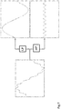
- Fig. 7 shows an advantageous division of the overall correction profile into WGTC and IPC, which consists in counteracting low-frequency form deviations using WGTC and the first correction profile and high-frequency form deviations using IPC and the second correction profile.
- a crossover is preferably used that uses a low-pass filter (LP) and a high-pass filter (HP) to assign low-frequency components of the shape deviation to a correction using WGTC and high-frequency components of the shape deviation to a correction using IPC.
- LP low-pass filter
- HP high-pass filter
- Fig. 8 shows that by means of the combination of WGTC and IPC, a larger total amplitude A2 + A1 per time unit ⁇ t can be brought about, because the movement of the floating bearings and the workpiece is carried out by two independent actuators.
- WGTC or IPC alone, only an amplitude of A1 or A2 is possible in this time unit.
- Fig. 9 shows how an advantageous division of the overall correction profile into WGTC and IPC dampens an overshoot of the amplitude A over the course of time t (right figure), which would be observed as the only measure if WGTC were used (left figure).
Landscapes
- Engineering & Computer Science (AREA)
- Mechanical Engineering (AREA)
- Processing Of Stones Or Stones Resemblance Materials (AREA)
- Finish Polishing, Edge Sharpening, And Grinding By Specific Grinding Devices (AREA)
- Mechanical Treatment Of Semiconductor (AREA)
- Constituent Portions Of Griding Lathes, Driving, Sensing And Control (AREA)
- Sawing (AREA)
- Grinding-Machine Dressing And Accessory Apparatuses (AREA)
Priority Applications (7)
| Application Number | Priority Date | Filing Date | Title |
|---|---|---|---|
| EP20179134.0A EP3922385A1 (fr) | 2020-06-10 | 2020-06-10 | Procédé de séparation d'une pluralité de disques à partir de pièces au moyen d'une scie à fil lors d'une séquence de processus de séparation |
| TW110119352A TWI795792B (zh) | 2020-06-10 | 2021-05-28 | 在一系列切割操作期間用線鋸從工件上切割多個薄片的方法 |
| KR1020237000210A KR102781210B1 (ko) | 2020-06-10 | 2021-06-07 | 일련의 분리 프로세스 도중에 와이어 톱에 의해 공작물로부터 복수의 조각을 분리하기 위한 방법 |
| JP2022576144A JP2023534608A (ja) | 2020-06-10 | 2021-06-07 | 一連の切断動作中にワイヤソーによって被加工物から複数のスライスを切断する方法 |
| PCT/EP2021/062691 WO2021249719A1 (fr) | 2020-06-10 | 2021-06-07 | Procédé de séparation d'une pluralité de tranches de pièces de fabrication au moyen d'une scie à fil lors d'une séquence de traitement de séparation |
| US17/928,933 US12325081B2 (en) | 2020-06-10 | 2021-06-07 | Method for separating a plurality of slices from workpieces by means of a wire saw during a sequence of separation processes |
| CN202180041951.1A CN116018227B (zh) | 2020-06-10 | 2021-06-07 | 在一系列切下操作期间借助于线锯从工件切割多个切片的方法 |
Applications Claiming Priority (1)
| Application Number | Priority Date | Filing Date | Title |
|---|---|---|---|
| EP20179134.0A EP3922385A1 (fr) | 2020-06-10 | 2020-06-10 | Procédé de séparation d'une pluralité de disques à partir de pièces au moyen d'une scie à fil lors d'une séquence de processus de séparation |
Publications (1)
| Publication Number | Publication Date |
|---|---|
| EP3922385A1 true EP3922385A1 (fr) | 2021-12-15 |
Family
ID=71083471
Family Applications (1)
| Application Number | Title | Priority Date | Filing Date |
|---|---|---|---|
| EP20179134.0A Pending EP3922385A1 (fr) | 2020-06-10 | 2020-06-10 | Procédé de séparation d'une pluralité de disques à partir de pièces au moyen d'une scie à fil lors d'une séquence de processus de séparation |
Country Status (7)
| Country | Link |
|---|---|
| US (1) | US12325081B2 (fr) |
| EP (1) | EP3922385A1 (fr) |
| JP (1) | JP2023534608A (fr) |
| KR (1) | KR102781210B1 (fr) |
| CN (1) | CN116018227B (fr) |
| TW (1) | TWI795792B (fr) |
| WO (1) | WO2021249719A1 (fr) |
Cited By (1)
| Publication number | Priority date | Publication date | Assignee | Title |
|---|---|---|---|---|
| CN117047192A (zh) * | 2023-10-09 | 2023-11-14 | 成都易德莱斯科技有限公司 | 一种用于管道切割的绳锯机 |
Families Citing this family (2)
| Publication number | Priority date | Publication date | Assignee | Title |
|---|---|---|---|---|
| EP3922388A1 (fr) * | 2020-06-10 | 2021-12-15 | Siltronic AG | Procédé de séparation d'une pluralité de tranches, au moyen d'une scie à fil, de pièces lors d'une séquence de processus de séparation |
| CN120606461B (zh) * | 2025-08-12 | 2025-11-11 | 内蒙古晶环电子材料有限公司 | 一种切片机的切割方法和切片机 |
Citations (5)
| Publication number | Priority date | Publication date | Assignee | Title |
|---|---|---|---|---|
| US5377568A (en) | 1992-01-22 | 1995-01-03 | Hauser; Charles | Device for controlling the cutting geometry of fine slices obtained by thread sawing |
| US5875770A (en) | 1996-04-22 | 1999-03-02 | Komatsu Electronic Metals Co., Ltd. | Method of cutting semiconductor ingots and apparatus for cutting thereof |
| JP2005103683A (ja) * | 2003-09-29 | 2005-04-21 | Toshiba Ceramics Co Ltd | ワイヤソー |
| DE102011005949A1 (de) * | 2011-03-23 | 2012-09-27 | Siltronic Ag | Verfahren zum Abtrennen von Scheiben von einem Werkstück |
| WO2013079683A1 (fr) | 2011-12-01 | 2013-06-06 | Memc Electronic Materials S.P.A. | Systèmes et procédés permettant de contrôler les profils de surface de plaquettes tranchées dans une machine à scier à fil |
Family Cites Families (12)
| Publication number | Priority date | Publication date | Assignee | Title |
|---|---|---|---|---|
| JP2002301659A (ja) * | 2001-04-03 | 2002-10-15 | Kawasaki Heavy Ind Ltd | 自動仕上げ方法および装置 |
| JP4308463B2 (ja) * | 2001-11-08 | 2009-08-05 | 株式会社Sumco | ワイヤソー |
| JP4314582B2 (ja) * | 2004-11-29 | 2009-08-19 | 株式会社Sumco | ワイヤソーを用いたワーク切断方法 |
| JP4816511B2 (ja) * | 2007-03-06 | 2011-11-16 | 信越半導体株式会社 | 切断方法およびワイヤソー装置 |
| JP5056859B2 (ja) * | 2007-12-19 | 2012-10-24 | 信越半導体株式会社 | ワイヤソーによるワークの切断方法およびワイヤソー |
| JP2009196023A (ja) * | 2008-02-20 | 2009-09-03 | Toyo Advanced Technologies Co Ltd | ワイヤソー |
| DE102011082366B3 (de) * | 2011-09-08 | 2013-02-28 | Siltronic Ag | Einlagiges Wickeln von Sägedraht mit fest gebundenem Schneidkorn für Drahtsägen zum Abtrennen von Scheiben von einem Werkstück |
| CN203061980U (zh) * | 2011-12-22 | 2013-07-17 | 应用材料瑞士有限责任公司 | 线锯设备、线锯集群及线锯工厂 |
| DE102014208187B4 (de) * | 2014-04-30 | 2023-07-06 | Siltronic Ag | Verfahren zum gleichzeitigen Trennen einer Vielzahl von Scheiben mit besonders gleichmäßiger Dicke von einem Werkstück |
| US10315337B2 (en) * | 2016-08-25 | 2019-06-11 | GlobalWafers Co. Ltd. | Methods and system for controlling a surface profile of a wafer |
| JP6222393B1 (ja) | 2017-03-21 | 2017-11-01 | 信越半導体株式会社 | インゴットの切断方法 |
| CN109865887A (zh) * | 2019-03-29 | 2019-06-11 | 上海易具精密工具股份有限公司 | 一种远程锯切系统 |
-
2020
- 2020-06-10 EP EP20179134.0A patent/EP3922385A1/fr active Pending
-
2021
- 2021-05-28 TW TW110119352A patent/TWI795792B/zh active
- 2021-06-07 JP JP2022576144A patent/JP2023534608A/ja active Pending
- 2021-06-07 US US17/928,933 patent/US12325081B2/en active Active
- 2021-06-07 WO PCT/EP2021/062691 patent/WO2021249719A1/fr not_active Ceased
- 2021-06-07 CN CN202180041951.1A patent/CN116018227B/zh active Active
- 2021-06-07 KR KR1020237000210A patent/KR102781210B1/ko active Active
Patent Citations (5)
| Publication number | Priority date | Publication date | Assignee | Title |
|---|---|---|---|---|
| US5377568A (en) | 1992-01-22 | 1995-01-03 | Hauser; Charles | Device for controlling the cutting geometry of fine slices obtained by thread sawing |
| US5875770A (en) | 1996-04-22 | 1999-03-02 | Komatsu Electronic Metals Co., Ltd. | Method of cutting semiconductor ingots and apparatus for cutting thereof |
| JP2005103683A (ja) * | 2003-09-29 | 2005-04-21 | Toshiba Ceramics Co Ltd | ワイヤソー |
| DE102011005949A1 (de) * | 2011-03-23 | 2012-09-27 | Siltronic Ag | Verfahren zum Abtrennen von Scheiben von einem Werkstück |
| WO2013079683A1 (fr) | 2011-12-01 | 2013-06-06 | Memc Electronic Materials S.P.A. | Systèmes et procédés permettant de contrôler les profils de surface de plaquettes tranchées dans une machine à scier à fil |
Cited By (2)
| Publication number | Priority date | Publication date | Assignee | Title |
|---|---|---|---|---|
| CN117047192A (zh) * | 2023-10-09 | 2023-11-14 | 成都易德莱斯科技有限公司 | 一种用于管道切割的绳锯机 |
| CN117047192B (zh) * | 2023-10-09 | 2023-12-29 | 成都易德莱斯科技有限公司 | 一种用于管道切割的绳锯机 |
Also Published As
| Publication number | Publication date |
|---|---|
| JP2023534608A (ja) | 2023-08-10 |
| TW202146137A (zh) | 2021-12-16 |
| CN116018227A (zh) | 2023-04-25 |
| US12325081B2 (en) | 2025-06-10 |
| WO2021249719A1 (fr) | 2021-12-16 |
| KR102781210B1 (ko) | 2025-03-12 |
| TWI795792B (zh) | 2023-03-11 |
| US20230226629A1 (en) | 2023-07-20 |
| KR20230019200A (ko) | 2023-02-07 |
| CN116018227B (zh) | 2026-04-21 |
Similar Documents
| Publication | Publication Date | Title |
|---|---|---|
| EP3922387A1 (fr) | Procédé de séparation d'une pluralité de tranches, au moyen d'une scie à fil, de pièces lors d'une séquence de processus de séparation | |
| DE10122628B4 (de) | Verfahren zum Abtrennen von Scheiben von einem Werkstück | |
| DE102011005949B4 (de) | Verfahren zum Abtrennen von Scheiben von einem Werkstück | |
| WO2021249735A1 (fr) | Procédé de séparation d'une pluralité de tranches, à partir de pièces à travailler, au moyen d'une scie à fil, au cours d'une séquence de processus de séparation | |
| EP0733429B1 (fr) | Scie à fil et procédé pour la coupe des plaquettes d'une pièce | |
| EP4300542B1 (fr) | Procédé de fabrication de tranches de semi-conducteur au moyen d'une scie à fil, scie à fil et tranche de semi-conducteur en silicium monocristallin | |
| WO2021249719A1 (fr) | Procédé de séparation d'une pluralité de tranches de pièces de fabrication au moyen d'une scie à fil lors d'une séquence de traitement de séparation | |
| WO2021249781A1 (fr) | Procédé de séparation d'une pluralité de tranches, à partir de pièces à travailler, au moyen d'une scie à fil, pendant une séquence de processus de séparation | |
| EP3976335A1 (fr) | Procédé de séparation d'une pluralité de tranches de pièces au cours d'un nombre d'opérations de séparation au moyen d'une scie à fil et tranche de semi-conducteur composée de silicium monocristallin | |
| DE102014103240A1 (de) | Verfahren zur Einrichtung und/oder Überwachung von Betriebsparametern einer Werkstückbearbeitungsmaschine | |
| DE102006058823A1 (de) | Verfahren zum Abtrennen einer Vielzahl von Scheiben von einem Werkstück | |
| DE102016108498A1 (de) | Bearbeitungssystem zum anpassen der drehzahl eines bearbeitungswerkzeugs und der vorschubgeschwindigkeit eines werkstücks | |
| DE102012209974B4 (de) | Verfahren zum gleichzeitigen Abtrennen einer Vielzahl von Scheiben von einem zylindrischen Werkstück | |
| EP3858569A1 (fr) | Procédé de séparation d'une pluralité de disques à partir de pièces au moyen d'une scie à fil lors d'une séquence de processus de séparation | |
| DE102011005948B4 (de) | Verfahren zum Abtrennen von Scheiben von einem Werkstück | |
| EP3922389A1 (fr) | Procédé de séparation d'une pluralité de tranches, au moyen d'une scie à fil, de pièces lors d'une séquence de processus de séparation | |
| EP3898151B1 (fr) | Procédé de fabrication de tranches de semi-conducteur au moyen d'une scie à fil | |
| DE112015003019T5 (de) | Schneidvorrichtung und schneidverfahren | |
| EP0432637B1 (fr) | Dispositif pour dresser le tranchant d'un outil de tronçonnage lors du tronçonnage de tranches d'un barreau ou d'une pièce en bloc, en particulier d'un matériau semi-conducteur, son application et procédé de sciage | |
| EP1757419B1 (fr) | Procédé, dispositif et boue pour le sciage à fil | |
| WO2024121052A1 (fr) | Procédé de séparation de multiples tranches d'une pièce au moyen d'une scie à fil pendant un processus de séparation | |
| DE102014208304A1 (de) | Maschine zum Bearbeiten von Holzplatten | |
| DE102014215726B3 (de) | Verfahren und Vorrichtung zum gleichzeitigen Abtrennen einer Vielzahl von Scheiben von einem Werkstück | |
| DE3817784C2 (fr) | ||
| DE102018212734B4 (de) | Verfahren zum gleichzeitigen Abtrennen einer Vielzahl von Scheiben von einem Stab |
Legal Events
| Date | Code | Title | Description |
|---|---|---|---|
| PUAI | Public reference made under article 153(3) epc to a published international application that has entered the european phase |
Free format text: ORIGINAL CODE: 0009012 |
|
| STAA | Information on the status of an ep patent application or granted ep patent |
Free format text: STATUS: THE APPLICATION HAS BEEN PUBLISHED |
|
| AK | Designated contracting states |
Kind code of ref document: A1 Designated state(s): AL AT BE BG CH CY CZ DE DK EE ES FI FR GB GR HR HU IE IS IT LI LT LU LV MC MK MT NL NO PL PT RO RS SE SI SK SM TR |
|
| B565 | Issuance of search results under rule 164(2) epc |
Effective date: 20201204 |
|
| STAA | Information on the status of an ep patent application or granted ep patent |
Free format text: STATUS: REQUEST FOR EXAMINATION WAS MADE |
|
| 17P | Request for examination filed |
Effective date: 20220217 |
|
| RBV | Designated contracting states (corrected) |
Designated state(s): AL AT BE BG CH CY CZ DE DK EE ES FI FR GB GR HR HU IE IS IT LI LT LU LV MC MK MT NL NO PL PT RO RS SE SI SK SM TR |
|
| STAA | Information on the status of an ep patent application or granted ep patent |
Free format text: STATUS: EXAMINATION IS IN PROGRESS |
|
| 17Q | First examination report despatched |
Effective date: 20220518 |