EP3922498B1 - Réservoir de détente pour un véhicule avec deux lignes de refroidissement, système de refroidissement et procédé de remplissage de réservoir de détente - Google Patents
Réservoir de détente pour un véhicule avec deux lignes de refroidissement, système de refroidissement et procédé de remplissage de réservoir de détente Download PDFInfo
- Publication number
- EP3922498B1 EP3922498B1 EP20179478.1A EP20179478A EP3922498B1 EP 3922498 B1 EP3922498 B1 EP 3922498B1 EP 20179478 A EP20179478 A EP 20179478A EP 3922498 B1 EP3922498 B1 EP 3922498B1
- Authority
- EP
- European Patent Office
- Prior art keywords
- expansion tank
- fluid
- chamber
- pressure
- cooling
- Prior art date
- Legal status (The legal status is an assumption and is not a legal conclusion. Google has not performed a legal analysis and makes no representation as to the accuracy of the status listed.)
- Active
Links
Images


Classifications
-
- B—PERFORMING OPERATIONS; TRANSPORTING
- B60—VEHICLES IN GENERAL
- B60K—ARRANGEMENT OR MOUNTING OF PROPULSION UNITS OR OF TRANSMISSIONS IN VEHICLES; ARRANGEMENT OR MOUNTING OF PLURAL DIVERSE PRIME-MOVERS IN VEHICLES; AUXILIARY DRIVES FOR VEHICLES; INSTRUMENTATION OR DASHBOARDS FOR VEHICLES; ARRANGEMENTS IN CONNECTION WITH COOLING, AIR INTAKE, GAS EXHAUST OR FUEL SUPPLY OF PROPULSION UNITS IN VEHICLES
- B60K11/00—Arrangement in connection with cooling of propulsion units
- B60K11/02—Arrangement in connection with cooling of propulsion units with liquid cooling
-
- F—MECHANICAL ENGINEERING; LIGHTING; HEATING; WEAPONS; BLASTING
- F01—MACHINES OR ENGINES IN GENERAL; ENGINE PLANTS IN GENERAL; STEAM ENGINES
- F01P—COOLING OF MACHINES OR ENGINES IN GENERAL; COOLING OF INTERNAL-COMBUSTION ENGINES
- F01P11/00—Component parts, details, or accessories not provided for in, or of interest apart from, groups F01P1/00 - F01P9/00
- F01P11/02—Liquid-coolant filling, overflow, venting, or draining devices
- F01P11/029—Expansion reservoirs
-
- F—MECHANICAL ENGINEERING; LIGHTING; HEATING; WEAPONS; BLASTING
- F01—MACHINES OR ENGINES IN GENERAL; ENGINE PLANTS IN GENERAL; STEAM ENGINES
- F01P—COOLING OF MACHINES OR ENGINES IN GENERAL; COOLING OF INTERNAL-COMBUSTION ENGINES
- F01P3/00—Liquid cooling
- F01P3/12—Arrangements for cooling other engine or machine parts
-
- F—MECHANICAL ENGINEERING; LIGHTING; HEATING; WEAPONS; BLASTING
- F01—MACHINES OR ENGINES IN GENERAL; ENGINE PLANTS IN GENERAL; STEAM ENGINES
- F01P—COOLING OF MACHINES OR ENGINES IN GENERAL; COOLING OF INTERNAL-COMBUSTION ENGINES
- F01P3/00—Liquid cooling
- F01P3/20—Cooling circuits not specific to a single part of engine or machine
-
- B—PERFORMING OPERATIONS; TRANSPORTING
- B60—VEHICLES IN GENERAL
- B60K—ARRANGEMENT OR MOUNTING OF PROPULSION UNITS OR OF TRANSMISSIONS IN VEHICLES; ARRANGEMENT OR MOUNTING OF PLURAL DIVERSE PRIME-MOVERS IN VEHICLES; AUXILIARY DRIVES FOR VEHICLES; INSTRUMENTATION OR DASHBOARDS FOR VEHICLES; ARRANGEMENTS IN CONNECTION WITH COOLING, AIR INTAKE, GAS EXHAUST OR FUEL SUPPLY OF PROPULSION UNITS IN VEHICLES
- B60K1/00—Arrangement or mounting of electrical propulsion units
- B60K2001/003—Arrangement or mounting of electrical propulsion units with means for cooling the electrical propulsion units
- B60K2001/005—Arrangement or mounting of electrical propulsion units with means for cooling the electrical propulsion units the electric storage means
-
- B—PERFORMING OPERATIONS; TRANSPORTING
- B60—VEHICLES IN GENERAL
- B60K—ARRANGEMENT OR MOUNTING OF PROPULSION UNITS OR OF TRANSMISSIONS IN VEHICLES; ARRANGEMENT OR MOUNTING OF PLURAL DIVERSE PRIME-MOVERS IN VEHICLES; AUXILIARY DRIVES FOR VEHICLES; INSTRUMENTATION OR DASHBOARDS FOR VEHICLES; ARRANGEMENTS IN CONNECTION WITH COOLING, AIR INTAKE, GAS EXHAUST OR FUEL SUPPLY OF PROPULSION UNITS IN VEHICLES
- B60K1/00—Arrangement or mounting of electrical propulsion units
- B60K2001/003—Arrangement or mounting of electrical propulsion units with means for cooling the electrical propulsion units
- B60K2001/006—Arrangement or mounting of electrical propulsion units with means for cooling the electrical propulsion units the electric motors
-
- F—MECHANICAL ENGINEERING; LIGHTING; HEATING; WEAPONS; BLASTING
- F01—MACHINES OR ENGINES IN GENERAL; ENGINE PLANTS IN GENERAL; STEAM ENGINES
- F01P—COOLING OF MACHINES OR ENGINES IN GENERAL; COOLING OF INTERNAL-COMBUSTION ENGINES
- F01P7/00—Controlling of coolant flow
- F01P7/14—Controlling of coolant flow the coolant being liquid
- F01P2007/146—Controlling of coolant flow the coolant being liquid using valves
-
- F—MECHANICAL ENGINEERING; LIGHTING; HEATING; WEAPONS; BLASTING
- F01—MACHINES OR ENGINES IN GENERAL; ENGINE PLANTS IN GENERAL; STEAM ENGINES
- F01P—COOLING OF MACHINES OR ENGINES IN GENERAL; COOLING OF INTERNAL-COMBUSTION ENGINES
- F01P11/00—Component parts, details, or accessories not provided for in, or of interest apart from, groups F01P1/00 - F01P9/00
- F01P11/02—Liquid-coolant filling, overflow, venting, or draining devices
- F01P11/0204—Filling
- F01P11/0209—Closure caps
- F01P11/0238—Closure caps with overpressure valves or vent valves
- F01P2011/0242—Closure caps with overpressure valves or vent valves setting the pressure valve
-
- F—MECHANICAL ENGINEERING; LIGHTING; HEATING; WEAPONS; BLASTING
- F01—MACHINES OR ENGINES IN GENERAL; ENGINE PLANTS IN GENERAL; STEAM ENGINES
- F01P—COOLING OF MACHINES OR ENGINES IN GENERAL; COOLING OF INTERNAL-COMBUSTION ENGINES
- F01P2050/00—Applications
- F01P2050/24—Hybrid vehicles
Definitions
- ICE Internal Combustion Engines
- Such vehicles have been equipped with a cooling system to regulate the temperature of the ICE and to avoid over-heating the engine.
- These cooling systems are normally liquid cooling lines connected to an expansion tank for allowing thermal expansion of the liquid and a circulation pump driving the liquid in the system.
- KR 2012 0033588 discloses an expansion tank for a vehicle with dual cooling lines, comprising a first chamber, wherein the expansion tank comprises a first fluid connector in fluid connection with the first chamber for connection to a first cooling line, a second chamber, wherein the expansion tank comprises a second fluid connector in fluid connection with the second chamber for connection to a second cooling line,wherein the first chamber and the second chamber are in fluid connection via a valve.
- an expansion tank for a vehicle with dual cooling lines comprising a first chamber with a first fluid pressure, wherein the expansion tank comprises a first fluid connector in fluid connection with the first chamber for connection to a first cooling line, a second chamber with a second fluid pressure, wherein the expansion tank comprises a second fluid connector in fluid connection with the second chamber for connection to a second cooling line, wherein the first chamber and the second chamber are in fluid connection via a pressure actuated two-way valve that acts as a one-way valve open in the direction towards the second chamber at differential pressures between the second flud pressure and the first fluid pressure below a first predetermined differential pressure threshold and opens also in the direction towards the first chamber at differential pressures above the first predetermined differential pressure threshold.
- expansion tank An advantage with the expansion tank is that a single expansion tank can be used for two different fluid cooling lines with different pressures in each of the two cooling lines. This saves space in the vehicles where two cooling lines are required. If the liquid in the high pressure second chamber expands it will be able to expand into the first chamber, if the pressure is above the first predetermined differential pressure threshold.
- the expansion tank comprises an internal division wall between the first chamber and the second chamber, wherein the internal division wall has a first side surface and a second side surface opposite the first side surface, wherein the first side surface delimits the first chamber and the second side surface delimits the second chamber.
- An advantage with this embodiment is that the two chambers are located adjacent each other minimizing the size of the expansion tank and the space needed to fit it in a vehicle.
- the internal division wall comprises an opening forming a fluid connection between the first chamber and the second chamber and wherein the pressure actuated two-way valve is arranged in the opening, thus avoiding other fluid communication means between the two chambers as pipes or hoses.
- the filling cap further comprises an over pressure valve opening towards the environment for releasing fluid at differential pressures between the first fluid pressure in the first container and the ambient air pressure above a second predetermined differential pressure threshold pressure.
- a second predetermined differential pressure threshold pressure In normal cases it will only be air that is released through the over pressure valve. However, if the pressure raises above the second differential pressure threshold, e.g. if the liquid becomes too hot and thereby expands more than the available volume in the first cooling line, the pressure and liquid will be released through the over pressure valve. The cooling system is then protected from dangerously high pressures.
- the first predetermined differential pressure threshold is in the range of 0.2 bar to 3 bar above atmospheric pressure preferably around 0.7 bar.
- the exact first predetermined differential pressure threshold for the system is set by the individual desired pressure for each of the two cooling lines, which is determined by the type of driving lines in the vehicle.
- the second predetermined differential pressure threshold is in the range of 0 bar to 1.5 bar, preferably around 0.75 bar.
- the exact second predetermined differential pressure threshold for the system is set by the desired pressure for each of the first cooling line.
- the expansion tank further comprises a third fluid connector in fluid connection with the first chamber for connection to the first cooling line, wherein the first fluid connector and the third fluid connector act as inlet and outlet, respectively, for cooling fluid, or the other way around.
- An advantage with the third and fourth fluid connectors is that the cooling liquid can flow through the first and second chamber of the expansion tank, respectively, which makes gas retraction of any gas in the system easier.
- a coolant system for electric circuits in a vehicle with an electric drive line comprising an expansion tank according to the first aspect, the coolant system further comprising: a first cooling line for cooling a battery and a second cooling line for cooling a motor, wherein the first cooling line is connected to the first fluid connector of the expansion tank and the second cooling line is connected to the second fluid connector of the expansion tank.
- the coolant system may e.g. be installed in a hybrid vehicle with two different drive lines or a vehicle with one drive line but that require one cooling line for the battery and one cooling line for the engine.
- the fluid that is filled into the expansion tank is water with an optional anti-freezing component as water is a good heat exchanging liquid without being expensive.
- Other coolant liquids may be used if higher efficiency is needed.
- the motor is an Internal Combustion Engine. Internal Combustion Engines are convenient as they run on liquid fuels with extremely high energy density. According to some embodiments, the motor is an electric motor, which has the advantage of not emitting anything but heat during operation which may be desired for environmental reasons.
- a method for filling the expansion tank according to the first aspect or the coolant system according to the second aspect comprising the steps of evacuating the expansion tank creating a low pressure or vacuum forcing the pressure actuated two-way valve to open, filling the expansion tank with the liquid during low pressure.
- the internal division wall 8 comprises an opening 83 forming a fluid connection between the first chamber and the second chamber and wherein the pressure actuated two-way valve 9 is arranged in the opening.
- the first predetermined differential pressure threshold DP1 is in the range of 0.2 bar to 3 bar above atmospheric pressure.
- the exact setting for the pressure actuated two-way valve 9 is determined by the type of vehicle and the components that are to be temperature controlled by the first cooling line 12 and the second cooling line 13, respectively.
- the first predetermined differential pressure threshold DP1 is in preferred embodiment around 0.7 bar.
- the first chamber 2 further comprises a filling cap 4 for filling the expansion tank 1 with fluid 5.
- the filling cap 4 further comprises an over pressure valve 41 opening towards the environment for releasing fluid at differential pressures between the first fluid pressure P1 in the first container 2 and the ambient air pressure AP above a second predetermined differential pressure threshold pressure DP2. If the first cooling line 12 and the first chamber 2 for some reason reaches a dangerous over pressure, the over pressure valve 41 will open and let fluid in the second chamber out.
- the second predetermined differential pressure threshold DP2 is in the range of 0 bar to 1.5 bar depending on the desired operating pressure of the first cooling line 12.
- the second aspect of this invention is shown in Figure 5 and discloses a coolant system 11 for electric circuits in a vehicle with an electric drive line comprising an expansion tank 1 according to the first aspect.
- the system comprises a first cooling line 12 for cooling a battery 16 and a second cooling line 13 for cooling a motor 17,18.
- the first cooling line 12 is connected to the first fluid connector 31 of the expansion tank 1 and the second cooling line 13 is connected in parallel to the expansion tank 1 via the connectors 7 and 71.
- the first cooling line 12 further comprises a first circulation pump 14 for circulating the fluid in the first cooling line.
- the first cooling line also comprises a heat exchanger 19 for reducing the temperature in the first cooling line.
Landscapes
- Engineering & Computer Science (AREA)
- Chemical & Material Sciences (AREA)
- Combustion & Propulsion (AREA)
- Mechanical Engineering (AREA)
- General Engineering & Computer Science (AREA)
- Transportation (AREA)
- Cooling, Air Intake And Gas Exhaust, And Fuel Tank Arrangements In Propulsion Units (AREA)
- Filling Or Discharging Of Gas Storage Vessels (AREA)
Claims (15)
- Réservoir d'expansion (1) pour un véhicule à deux conduites de refroidissement (12, 13), comprenantune première chambre (2) avec une première pression de fluide (P1), le réservoir d'expansion (1) comprenant un premier connecteur de fluide (3) en liaison fluidique avec la première chambre (2) pour le raccordement à une première conduite de refroidissement (12),une deuxième chambre (6) avec une deuxième pression de fluide (P2), le réservoir d'expansion (1) comprenant un deuxième connecteur de fluide (7) en liaison fluidique avec la deuxième chambre (2) pour le raccordement à une deuxième conduite de refroidissement (13),dans lequel la première chambre (2) et la deuxième chambre (6) sont en liaison fluidique par l'intermédiaire d'une soupape à deux voies actionnée par pression (9) qui agit comme une soupape unidirectionnelle ouverte dans la direction vers la deuxième chambre (6) à des pressions différentielles entre la deuxième pression de fluide (P2) et la première pression de fluide (P1) en dessous d'un premier seuil de pression différentielle prédéterminé (DP1) et s'ouvre également dans la direction vers la première chambre (2) à des pressions différentielles au-dessus du premier seuil de pression différentielle prédéterminé (PD1).
- Réservoir d'expansion (1) selon la revendication 1, dans lequel le réservoir d'expansion (1) comprend une paroi de division intérieure (8) entre la première chambre (2) et la deuxième chambre (6), dans lequel la paroi de division intérieure (8) présente une première surface latérale (81) et une deuxième surface latérale (82) opposée à la première surface latérale, la première surface latérale délimitant la première chambre et la deuxième surface latérale délimitant la deuxième chambre.
- Réservoir d'expansion (1) selon la revendication 2, dans lequel la paroi de division intérieure (8) comprend une ouverture (83) formant une liaison fluidique entre la première chambre et la deuxième chambre, et dans lequel la soupape à deux voies actionnée par pression (9) est disposée dans l'ouverture.
- Réservoir d'expansion (1) selon la revendication 1, dans lequel le premier récipient (2) comprend en outre un bouchon de remplissage (4) pour remplir le réservoir d'expansion (1) avec du fluide (5).
- Réservoir d'expansion (1) selon la revendication 2, dans lequel le bouchon de remplissage (4) comprend en outre une soupape de surpression (41) s'ouvrant vers l'environnement pour libérer du fluide à des pressions différentielles entre la première pression de fluide (P1) dans le premier récipient (2) et la pression de l'air ambiant (AP) au-dessus d'une deuxième pression de seuil de pression différentielle prédéterminée (DP2).
- Réservoir d'expansion (1) selon l'une quelconque des revendications 1 à 3, dans lequel le premier seuil de pression différentielle prédéterminé (DP1) est dans la plage de 0,2 bar à 3 bars.
[Pression supérieure à la pression atmosphérique] - Réservoir d'expansion (1) selon l'une quelconque des revendications 1 à 3, dans lequel le premier seuil de pression différentielle prédéterminé (DP1) est d'environ 0,7 bar.
- Réservoir d'expansion (1) selon l'une quelconque des revendications 3 à 5, dans lequel le deuxième seuil de pression différentielle prédéterminé (DP2) est dans la plage de 0 bar à 1,5 bars.
- Réservoir d'expansion (1) selon l'une quelconque des revendications 3 à 6, dans lequel le deuxième seuil de pression différentielle prédéterminé (DP2) est d'environ 0,75 bar.
- Réservoir d'expansion (1) selon l'une quelconque des revendications précédentes, dans lequel le réservoir d'expansion (1) comprend en outre un troisième connecteur de fluide (31) en liaison fluidique avec la première chambre (2) pour le raccordement à la première conduite de refroidissement (12), dans lequel le premier connecteur de fluide (3) et le troisième connecteur de fluide (31) agissent comme respectivement entrée et sortie pour le fluide de refroidissement, ou inversement.
- Réservoir d'expansion (1) selon l'une quelconque des revendications précédentes, dans lequel le réservoir d'expansion (1) comprend en outre un quatrième connecteur de fluide (71) en liaison fluidique avec la deuxième chambre (2) pour le raccordement à la deuxième conduite de refroidissement (12), dans lequel le deuxième connecteur de fluide (7) et le quatrième connecteur de fluide (71) agissent comme respectivement entrée et sortie pour le fluide de refroidissement, ou inversement.
- Système de refroidissement (11) pour des circuits électriques dans un véhicule avec une ligne de transmission électrique comprenant un réservoir d'expansion (1) selon l'une quelconque des revendications précédentes, comprenant en outre :une première conduite de refroidissement (12) pour refroidir une batterie (16) et une deuxième conduite de refroidissement (13) pour refroidir un moteur (17, 18),dans lequel la première conduite de refroidissement (12) est reliée au premier connecteur de fluide (3) du réservoir d'expansion (1) et la deuxième conduite de refroidissement (13) est reliée au deuxième connecteur de fluide (7) du réservoir d'expansion (1) .
- Système de refroidissement (11) selon la revendication 12, dans lequel le fluide qui remplit le réservoir d'expansion (1) est de l'eau avec un composant antigel facultatif.
- Système de refroidissement (11) selon la revendication 12 ou 13, dans lequel le moteur (17, 18) est un moteur à combustion interne (17) ou un moteur électrique (18).
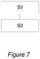
- Procédé de remplissage du réservoir d'expansion (1) selon l'une quelconque des revendications 1 à 11 ou du système de refroidissement (11) selon l'une quelconque des revendications 12 à 14, le procédé comprenant les étapes de
l'évacuation (S1) du réservoir d'expansion (1) créant une basse pression ou un vide forçant la soupape à deux voies actionnée par pression (9) à s'ouvrir, le remplissage (S2) du réservoir d'expansion avec le liquide (5) pendant une basse pression.
Priority Applications (4)
| Application Number | Priority Date | Filing Date | Title |
|---|---|---|---|
| EP20179478.1A EP3922498B1 (fr) | 2020-06-11 | 2020-06-11 | Réservoir de détente pour un véhicule avec deux lignes de refroidissement, système de refroidissement et procédé de remplissage de réservoir de détente |
| PCT/CN2021/093707 WO2021249107A1 (fr) | 2020-06-11 | 2021-05-13 | Réservoir d'expansion pour un véhicule à double conduite de refroidissement, système de refroidissement et procédé de remplissage du réservoir d'expansion |
| CN202180041126.1A CN115698478A (zh) | 2020-06-11 | 2021-05-13 | 用于具有双冷却线路的车辆的膨胀箱、冷却系统和用于填充膨胀箱的方法 |
| US17/988,441 US20230070793A1 (en) | 2020-06-11 | 2022-11-16 | Expansion tank for a vehicle with dual cooling lines, a coolant system and a method for filling the expansion tank |
Applications Claiming Priority (1)
| Application Number | Priority Date | Filing Date | Title |
|---|---|---|---|
| EP20179478.1A EP3922498B1 (fr) | 2020-06-11 | 2020-06-11 | Réservoir de détente pour un véhicule avec deux lignes de refroidissement, système de refroidissement et procédé de remplissage de réservoir de détente |
Publications (2)
| Publication Number | Publication Date |
|---|---|
| EP3922498A1 EP3922498A1 (fr) | 2021-12-15 |
| EP3922498B1 true EP3922498B1 (fr) | 2022-08-31 |
Family
ID=71092398
Family Applications (1)
| Application Number | Title | Priority Date | Filing Date |
|---|---|---|---|
| EP20179478.1A Active EP3922498B1 (fr) | 2020-06-11 | 2020-06-11 | Réservoir de détente pour un véhicule avec deux lignes de refroidissement, système de refroidissement et procédé de remplissage de réservoir de détente |
Country Status (4)
| Country | Link |
|---|---|
| US (1) | US20230070793A1 (fr) |
| EP (1) | EP3922498B1 (fr) |
| CN (1) | CN115698478A (fr) |
| WO (1) | WO2021249107A1 (fr) |
Families Citing this family (1)
| Publication number | Priority date | Publication date | Assignee | Title |
|---|---|---|---|---|
| NL2034974B1 (en) * | 2023-06-01 | 2024-12-10 | Daf Trucks Nv | Commercial vehicle comprising a cooling system for cooling an electric drive unit |
Family Cites Families (10)
| Publication number | Priority date | Publication date | Assignee | Title |
|---|---|---|---|---|
| US20110284107A1 (en) * | 2010-05-24 | 2011-11-24 | Mann+Hummel Gmbh | Multi-chamber fluid reservoir |
| KR101181045B1 (ko) * | 2010-09-30 | 2012-09-07 | 현대자동차주식회사 | 하이브리드 차량용 냉각수 리저버 탱크 |
| DE112011104946B4 (de) * | 2011-02-23 | 2018-10-11 | Suzuki Motor Corporation | Kühlvorrichtung für Hybridfahrzeuge |
| FR3000939B1 (fr) * | 2013-01-15 | 2015-10-02 | Tristone Flowtech Solutions Tfs | Reservoir de liquide et dispositif de regulation de la phase liquide d'un circuit de refroidissement d'un moteur thermique integrant un tel reservoir |
| SE540917C2 (en) * | 2015-09-15 | 2018-12-18 | Scania Cv Ab | A cooling arrangement for an electric power unit in a vehicle |
| SE539924C2 (en) * | 2016-05-23 | 2018-01-16 | Scania Cv Ab | Expansion tank and cooling system comprising such an expansion tank |
| CN206600198U (zh) * | 2017-01-24 | 2017-10-31 | 中国第一汽车股份有限公司 | 一种汽车双腔式膨胀水箱 |
| DE102018102235A1 (de) * | 2018-02-01 | 2019-08-01 | Man Truck & Bus Ag | Ausgleichsbehälter für Kühlkreisläufe mit unterschiedlichem Temperaturniveau und Druckaddition |
| WO2019203701A1 (fr) * | 2018-04-17 | 2019-10-24 | Scania Cv Ab | Système de refroidissement comprenant au moins deux circuits de refroidissement reliés à un réservoir d'expansion commun |
| CN208734425U (zh) * | 2018-08-31 | 2019-04-12 | 众泰新能源汽车有限公司 | 车用膨胀水箱 |
-
2020
- 2020-06-11 EP EP20179478.1A patent/EP3922498B1/fr active Active
-
2021
- 2021-05-13 CN CN202180041126.1A patent/CN115698478A/zh active Pending
- 2021-05-13 WO PCT/CN2021/093707 patent/WO2021249107A1/fr not_active Ceased
-
2022
- 2022-11-16 US US17/988,441 patent/US20230070793A1/en not_active Abandoned
Also Published As
| Publication number | Publication date |
|---|---|
| WO2021249107A1 (fr) | 2021-12-16 |
| US20230070793A1 (en) | 2023-03-09 |
| EP3922498A1 (fr) | 2021-12-15 |
| CN115698478A (zh) | 2023-02-03 |
Similar Documents
| Publication | Publication Date | Title |
|---|---|---|
| US9771853B2 (en) | Waste heat accumulator/distributor system | |
| US8689742B2 (en) | Integrated coolant flow control and heat exchanger device | |
| US11415084B2 (en) | Storage tank for cryogenic liquid gas | |
| CN101574923A (zh) | 用于车辆的电池热系统 | |
| CN201129245Y (zh) | 燃油防冻双层油箱 | |
| CN108666699B (zh) | 车辆电池的温度控制装置、具有这种温度控制装置的车辆以及用于控制车辆电池温度的方法 | |
| US20070272174A1 (en) | Thermal energy recovery and management system | |
| US9490509B2 (en) | Motor vehicle with battery cooling system | |
| CN115431839B (zh) | 一种燃料电池汽车整车热管理系统及控制方法 | |
| EP2192286A2 (fr) | Procédé et système pour le refroidissement supplémentaire du produit de refroidissement dans un système de refroidissement de véhicule | |
| CN107719102A (zh) | 新能源汽车双系统共用膨胀水箱 | |
| CN110872981A (zh) | 机动车辆的内燃发动机的冷却系统 | |
| CN216928640U (zh) | 一种燃料电池车尾排水收集系统 | |
| EP3922498B1 (fr) | Réservoir de détente pour un véhicule avec deux lignes de refroidissement, système de refroidissement et procédé de remplissage de réservoir de détente | |
| US20070044938A1 (en) | Dual surge tank for vehicle cooling system | |
| JP4941344B2 (ja) | 油圧システム | |
| WO2026061174A1 (fr) | Module intégré côté liquide de refroidissement de véhicule électrique hybride et système de gestion thermique | |
| EP2578838B1 (fr) | Système de refroidissement pour moteur | |
| CN211935292U (zh) | 消防车供热系统和消防车 | |
| CN221178275U (zh) | 一种液冷散热功率变换设备 | |
| US20250369677A1 (en) | High Power Passive Thermal Storage Heat Exchanger | |
| EP4663908A1 (fr) | Réservoir d'équilibrage de pression pour un système de refroidissement d'un véhicule automobile à propulsion électrique | |
| CN2377353Y (zh) | 水箱补水器 | |
| CN222296355U (zh) | 发动机冷却系统及车辆 | |
| CN112983623A (zh) | 一种防爆柴油机的冷却系统及其控制方法 |
Legal Events
| Date | Code | Title | Description |
|---|---|---|---|
| PUAI | Public reference made under article 153(3) epc to a published international application that has entered the european phase |
Free format text: ORIGINAL CODE: 0009012 |
|
| STAA | Information on the status of an ep patent application or granted ep patent |
Free format text: STATUS: REQUEST FOR EXAMINATION WAS MADE |
|
| 17P | Request for examination filed |
Effective date: 20200611 |
|
| AK | Designated contracting states |
Kind code of ref document: A1 Designated state(s): AL AT BE BG CH CY CZ DE DK EE ES FI FR GB GR HR HU IE IS IT LI LT LU LV MC MK MT NL NO PL PT RO RS SE SI SK SM TR |
|
| B565 | Issuance of search results under rule 164(2) epc |
Effective date: 20201002 |
|
| GRAP | Despatch of communication of intention to grant a patent |
Free format text: ORIGINAL CODE: EPIDOSNIGR1 |
|
| STAA | Information on the status of an ep patent application or granted ep patent |
Free format text: STATUS: GRANT OF PATENT IS INTENDED |
|
| INTG | Intention to grant announced |
Effective date: 20220413 |
|
| GRAS | Grant fee paid |
Free format text: ORIGINAL CODE: EPIDOSNIGR3 |
|
| GRAA | (expected) grant |
Free format text: ORIGINAL CODE: 0009210 |
|
| STAA | Information on the status of an ep patent application or granted ep patent |
Free format text: STATUS: THE PATENT HAS BEEN GRANTED |
|
| AK | Designated contracting states |
Kind code of ref document: B1 Designated state(s): AL AT BE BG CH CY CZ DE DK EE ES FI FR GB GR HR HU IE IS IT LI LT LU LV MC MK MT NL NO PL PT RO RS SE SI SK SM TR |
|
| REG | Reference to a national code |
Ref country code: CH Ref legal event code: EP Ref country code: GB Ref legal event code: FG4D |
|
| REG | Reference to a national code |
Ref country code: AT Ref legal event code: REF Ref document number: 1515049 Country of ref document: AT Kind code of ref document: T Effective date: 20220915 |
|
| REG | Reference to a national code |
Ref country code: DE Ref legal event code: R096 Ref document number: 602020004794 Country of ref document: DE |
|
| REG | Reference to a national code |
Ref country code: IE Ref legal event code: FG4D |
|
| REG | Reference to a national code |
Ref country code: LT Ref legal event code: MG9D |
|
| REG | Reference to a national code |
Ref country code: NL Ref legal event code: MP Effective date: 20220831 |
|
| PG25 | Lapsed in a contracting state [announced via postgrant information from national office to epo] |
Ref country code: SE Free format text: LAPSE BECAUSE OF FAILURE TO SUBMIT A TRANSLATION OF THE DESCRIPTION OR TO PAY THE FEE WITHIN THE PRESCRIBED TIME-LIMIT Effective date: 20220831 Ref country code: RS Free format text: LAPSE BECAUSE OF FAILURE TO SUBMIT A TRANSLATION OF THE DESCRIPTION OR TO PAY THE FEE WITHIN THE PRESCRIBED TIME-LIMIT Effective date: 20220831 Ref country code: NO Free format text: LAPSE BECAUSE OF FAILURE TO SUBMIT A TRANSLATION OF THE DESCRIPTION OR TO PAY THE FEE WITHIN THE PRESCRIBED TIME-LIMIT Effective date: 20221130 Ref country code: LV Free format text: LAPSE BECAUSE OF FAILURE TO SUBMIT A TRANSLATION OF THE DESCRIPTION OR TO PAY THE FEE WITHIN THE PRESCRIBED TIME-LIMIT Effective date: 20220831 Ref country code: LT Free format text: LAPSE BECAUSE OF FAILURE TO SUBMIT A TRANSLATION OF THE DESCRIPTION OR TO PAY THE FEE WITHIN THE PRESCRIBED TIME-LIMIT Effective date: 20220831 Ref country code: FI Free format text: LAPSE BECAUSE OF FAILURE TO SUBMIT A TRANSLATION OF THE DESCRIPTION OR TO PAY THE FEE WITHIN THE PRESCRIBED TIME-LIMIT Effective date: 20220831 |
|
| REG | Reference to a national code |
Ref country code: AT Ref legal event code: MK05 Ref document number: 1515049 Country of ref document: AT Kind code of ref document: T Effective date: 20220831 |
|
| PG25 | Lapsed in a contracting state [announced via postgrant information from national office to epo] |
Ref country code: PL Free format text: LAPSE BECAUSE OF FAILURE TO SUBMIT A TRANSLATION OF THE DESCRIPTION OR TO PAY THE FEE WITHIN THE PRESCRIBED TIME-LIMIT Effective date: 20220831 Ref country code: IS Free format text: LAPSE BECAUSE OF FAILURE TO SUBMIT A TRANSLATION OF THE DESCRIPTION OR TO PAY THE FEE WITHIN THE PRESCRIBED TIME-LIMIT Effective date: 20221231 Ref country code: HR Free format text: LAPSE BECAUSE OF FAILURE TO SUBMIT A TRANSLATION OF THE DESCRIPTION OR TO PAY THE FEE WITHIN THE PRESCRIBED TIME-LIMIT Effective date: 20220831 |
|
| PG25 | Lapsed in a contracting state [announced via postgrant information from national office to epo] |
Ref country code: SM Free format text: LAPSE BECAUSE OF FAILURE TO SUBMIT A TRANSLATION OF THE DESCRIPTION OR TO PAY THE FEE WITHIN THE PRESCRIBED TIME-LIMIT Effective date: 20220831 Ref country code: RO Free format text: LAPSE BECAUSE OF FAILURE TO SUBMIT A TRANSLATION OF THE DESCRIPTION OR TO PAY THE FEE WITHIN THE PRESCRIBED TIME-LIMIT Effective date: 20220831 Ref country code: PT Free format text: LAPSE BECAUSE OF FAILURE TO SUBMIT A TRANSLATION OF THE DESCRIPTION OR TO PAY THE FEE WITHIN THE PRESCRIBED TIME-LIMIT Effective date: 20230102 Ref country code: ES Free format text: LAPSE BECAUSE OF FAILURE TO SUBMIT A TRANSLATION OF THE DESCRIPTION OR TO PAY THE FEE WITHIN THE PRESCRIBED TIME-LIMIT Effective date: 20220831 Ref country code: DK Free format text: LAPSE BECAUSE OF FAILURE TO SUBMIT A TRANSLATION OF THE DESCRIPTION OR TO PAY THE FEE WITHIN THE PRESCRIBED TIME-LIMIT Effective date: 20220831 Ref country code: CZ Free format text: LAPSE BECAUSE OF FAILURE TO SUBMIT A TRANSLATION OF THE DESCRIPTION OR TO PAY THE FEE WITHIN THE PRESCRIBED TIME-LIMIT Effective date: 20220831 Ref country code: AT Free format text: LAPSE BECAUSE OF FAILURE TO SUBMIT A TRANSLATION OF THE DESCRIPTION OR TO PAY THE FEE WITHIN THE PRESCRIBED TIME-LIMIT Effective date: 20220831 |
|
| PG25 | Lapsed in a contracting state [announced via postgrant information from national office to epo] |
Ref country code: SK Free format text: LAPSE BECAUSE OF FAILURE TO SUBMIT A TRANSLATION OF THE DESCRIPTION OR TO PAY THE FEE WITHIN THE PRESCRIBED TIME-LIMIT Effective date: 20220831 Ref country code: EE Free format text: LAPSE BECAUSE OF FAILURE TO SUBMIT A TRANSLATION OF THE DESCRIPTION OR TO PAY THE FEE WITHIN THE PRESCRIBED TIME-LIMIT Effective date: 20220831 |
|
| REG | Reference to a national code |
Ref country code: DE Ref legal event code: R097 Ref document number: 602020004794 Country of ref document: DE |
|
| PG25 | Lapsed in a contracting state [announced via postgrant information from national office to epo] |
Ref country code: NL Free format text: LAPSE BECAUSE OF FAILURE TO SUBMIT A TRANSLATION OF THE DESCRIPTION OR TO PAY THE FEE WITHIN THE PRESCRIBED TIME-LIMIT Effective date: 20220831 Ref country code: AL Free format text: LAPSE BECAUSE OF FAILURE TO SUBMIT A TRANSLATION OF THE DESCRIPTION OR TO PAY THE FEE WITHIN THE PRESCRIBED TIME-LIMIT Effective date: 20220831 |
|
| PLBE | No opposition filed within time limit |
Free format text: ORIGINAL CODE: 0009261 |
|
| STAA | Information on the status of an ep patent application or granted ep patent |
Free format text: STATUS: NO OPPOSITION FILED WITHIN TIME LIMIT |
|
| 26N | No opposition filed |
Effective date: 20230601 |
|
| PG25 | Lapsed in a contracting state [announced via postgrant information from national office to epo] |
Ref country code: MC Free format text: LAPSE BECAUSE OF FAILURE TO SUBMIT A TRANSLATION OF THE DESCRIPTION OR TO PAY THE FEE WITHIN THE PRESCRIBED TIME-LIMIT Effective date: 20220831 |
|
| PG25 | Lapsed in a contracting state [announced via postgrant information from national office to epo] |
Ref country code: MC Free format text: LAPSE BECAUSE OF FAILURE TO SUBMIT A TRANSLATION OF THE DESCRIPTION OR TO PAY THE FEE WITHIN THE PRESCRIBED TIME-LIMIT Effective date: 20220831 |
|
| REG | Reference to a national code |
Ref country code: CH Ref legal event code: PL |
|
| REG | Reference to a national code |
Ref country code: BE Ref legal event code: MM Effective date: 20230630 |
|
| PG25 | Lapsed in a contracting state [announced via postgrant information from national office to epo] |
Ref country code: LU Free format text: LAPSE BECAUSE OF NON-PAYMENT OF DUE FEES Effective date: 20230611 |
|
| REG | Reference to a national code |
Ref country code: IE Ref legal event code: MM4A |
|
| PG25 | Lapsed in a contracting state [announced via postgrant information from national office to epo] |
Ref country code: LU Free format text: LAPSE BECAUSE OF NON-PAYMENT OF DUE FEES Effective date: 20230611 |
|
| PG25 | Lapsed in a contracting state [announced via postgrant information from national office to epo] |
Ref country code: IE Free format text: LAPSE BECAUSE OF NON-PAYMENT OF DUE FEES Effective date: 20230611 |
|
| PG25 | Lapsed in a contracting state [announced via postgrant information from national office to epo] |
Ref country code: IE Free format text: LAPSE BECAUSE OF NON-PAYMENT OF DUE FEES Effective date: 20230611 Ref country code: CH Free format text: LAPSE BECAUSE OF NON-PAYMENT OF DUE FEES Effective date: 20230630 |
|
| PG25 | Lapsed in a contracting state [announced via postgrant information from national office to epo] |
Ref country code: IT Free format text: LAPSE BECAUSE OF FAILURE TO SUBMIT A TRANSLATION OF THE DESCRIPTION OR TO PAY THE FEE WITHIN THE PRESCRIBED TIME-LIMIT Effective date: 20220831 Ref country code: BE Free format text: LAPSE BECAUSE OF NON-PAYMENT OF DUE FEES Effective date: 20230630 |
|
| PG25 | Lapsed in a contracting state [announced via postgrant information from national office to epo] |
Ref country code: BG Free format text: LAPSE BECAUSE OF FAILURE TO SUBMIT A TRANSLATION OF THE DESCRIPTION OR TO PAY THE FEE WITHIN THE PRESCRIBED TIME-LIMIT Effective date: 20220831 |
|
| PG25 | Lapsed in a contracting state [announced via postgrant information from national office to epo] |
Ref country code: BG Free format text: LAPSE BECAUSE OF FAILURE TO SUBMIT A TRANSLATION OF THE DESCRIPTION OR TO PAY THE FEE WITHIN THE PRESCRIBED TIME-LIMIT Effective date: 20220831 |
|
| PGFP | Annual fee paid to national office [announced via postgrant information from national office to epo] |
Ref country code: DE Payment date: 20250618 Year of fee payment: 6 |
|
| PGFP | Annual fee paid to national office [announced via postgrant information from national office to epo] |
Ref country code: GB Payment date: 20250402 Year of fee payment: 6 |
|
| PGFP | Annual fee paid to national office [announced via postgrant information from national office to epo] |
Ref country code: FR Payment date: 20250515 Year of fee payment: 6 |
|
| PG25 | Lapsed in a contracting state [announced via postgrant information from national office to epo] |
Ref country code: CY Free format text: LAPSE BECAUSE OF FAILURE TO SUBMIT A TRANSLATION OF THE DESCRIPTION OR TO PAY THE FEE WITHIN THE PRESCRIBED TIME-LIMIT; INVALID AB INITIO Effective date: 20200611 |
|
| PG25 | Lapsed in a contracting state [announced via postgrant information from national office to epo] |
Ref country code: HU Free format text: LAPSE BECAUSE OF FAILURE TO SUBMIT A TRANSLATION OF THE DESCRIPTION OR TO PAY THE FEE WITHIN THE PRESCRIBED TIME-LIMIT; INVALID AB INITIO Effective date: 20200611 |
|
| PG25 | Lapsed in a contracting state [announced via postgrant information from national office to epo] |
Ref country code: GR Free format text: LAPSE BECAUSE OF FAILURE TO SUBMIT A TRANSLATION OF THE DESCRIPTION OR TO PAY THE FEE WITHIN THE PRESCRIBED TIME-LIMIT; INVALID AB INITIO Effective date: 20200611 |
|
| PG25 | Lapsed in a contracting state [announced via postgrant information from national office to epo] |
Ref country code: TR Free format text: LAPSE BECAUSE OF FAILURE TO SUBMIT A TRANSLATION OF THE DESCRIPTION OR TO PAY THE FEE WITHIN THE PRESCRIBED TIME-LIMIT Effective date: 20220831 |
|
| PG25 | Lapsed in a contracting state [announced via postgrant information from national office to epo] |
Ref country code: SI Free format text: LAPSE BECAUSE OF FAILURE TO SUBMIT A TRANSLATION OF THE DESCRIPTION OR TO PAY THE FEE WITHIN THE PRESCRIBED TIME-LIMIT Effective date: 20220831 |