EP3922711A1 - Dispositif de traitement d'échantillon - Google Patents
Dispositif de traitement d'échantillon Download PDFInfo
- Publication number
- EP3922711A1 EP3922711A1 EP20752716.9A EP20752716A EP3922711A1 EP 3922711 A1 EP3922711 A1 EP 3922711A1 EP 20752716 A EP20752716 A EP 20752716A EP 3922711 A1 EP3922711 A1 EP 3922711A1
- Authority
- EP
- European Patent Office
- Prior art keywords
- sample
- treating
- biological substance
- stage
- unit
- Prior art date
- Legal status (The legal status is an assumption and is not a legal conclusion. Google has not performed a legal analysis and makes no representation as to the accuracy of the status listed.)
- Pending
Links
Images



Classifications
-
- C—CHEMISTRY; METALLURGY
- C12—BIOCHEMISTRY; BEER; SPIRITS; WINE; VINEGAR; MICROBIOLOGY; ENZYMOLOGY; MUTATION OR GENETIC ENGINEERING
- C12M—APPARATUS FOR ENZYMOLOGY OR MICROBIOLOGY; APPARATUS FOR CULTURING MICROORGANISMS FOR PRODUCING BIOMASS, FOR GROWING CELLS OR FOR OBTAINING FERMENTATION OR METABOLIC PRODUCTS, i.e. BIOREACTORS OR FERMENTERS
- C12M27/00—Means for mixing, agitating or circulating fluids in the vessel
- C12M27/14—Rotation or movement of the cells support, e.g. rotated hollow fibers
-
- B—PERFORMING OPERATIONS; TRANSPORTING
- B03—SEPARATION OF SOLID MATERIALS USING LIQUIDS OR USING PNEUMATIC TABLES OR JIGS; MAGNETIC OR ELECTROSTATIC SEPARATION OF SOLID MATERIALS FROM SOLID MATERIALS OR FLUIDS; SEPARATION BY HIGH-VOLTAGE ELECTRIC FIELDS
- B03C—MAGNETIC OR ELECTROSTATIC SEPARATION OF SOLID MATERIALS FROM SOLID MATERIALS OR FLUIDS; SEPARATION BY HIGH-VOLTAGE ELECTRIC FIELDS
- B03C1/00—Magnetic separation
- B03C1/005—Pretreatment specially adapted for magnetic separation
- B03C1/01—Pretreatment specially adapted for magnetic separation by addition of magnetic adjuvants
-
- B—PERFORMING OPERATIONS; TRANSPORTING
- B03—SEPARATION OF SOLID MATERIALS USING LIQUIDS OR USING PNEUMATIC TABLES OR JIGS; MAGNETIC OR ELECTROSTATIC SEPARATION OF SOLID MATERIALS FROM SOLID MATERIALS OR FLUIDS; SEPARATION BY HIGH-VOLTAGE ELECTRIC FIELDS
- B03C—MAGNETIC OR ELECTROSTATIC SEPARATION OF SOLID MATERIALS FROM SOLID MATERIALS OR FLUIDS; SEPARATION BY HIGH-VOLTAGE ELECTRIC FIELDS
- B03C1/00—Magnetic separation
- B03C1/02—Magnetic separation acting directly on the substance being separated
- B03C1/28—Magnetic plugs and dipsticks
- B03C1/286—Magnetic plugs and dipsticks disposed at the inner circumference of a recipient, e.g. magnetic drain bolt
-
- B—PERFORMING OPERATIONS; TRANSPORTING
- B03—SEPARATION OF SOLID MATERIALS USING LIQUIDS OR USING PNEUMATIC TABLES OR JIGS; MAGNETIC OR ELECTROSTATIC SEPARATION OF SOLID MATERIALS FROM SOLID MATERIALS OR FLUIDS; SEPARATION BY HIGH-VOLTAGE ELECTRIC FIELDS
- B03C—MAGNETIC OR ELECTROSTATIC SEPARATION OF SOLID MATERIALS FROM SOLID MATERIALS OR FLUIDS; SEPARATION BY HIGH-VOLTAGE ELECTRIC FIELDS
- B03C1/00—Magnetic separation
- B03C1/02—Magnetic separation acting directly on the substance being separated
- B03C1/28—Magnetic plugs and dipsticks
- B03C1/288—Magnetic plugs and dipsticks disposed at the outer circumference of a recipient
-
- C—CHEMISTRY; METALLURGY
- C12—BIOCHEMISTRY; BEER; SPIRITS; WINE; VINEGAR; MICROBIOLOGY; ENZYMOLOGY; MUTATION OR GENETIC ENGINEERING
- C12M—APPARATUS FOR ENZYMOLOGY OR MICROBIOLOGY; APPARATUS FOR CULTURING MICROORGANISMS FOR PRODUCING BIOMASS, FOR GROWING CELLS OR FOR OBTAINING FERMENTATION OR METABOLIC PRODUCTS, i.e. BIOREACTORS OR FERMENTERS
- C12M23/00—Constructional details, e.g. recesses, hinges
- C12M23/48—Holding appliances; Racks; Supports
-
- C—CHEMISTRY; METALLURGY
- C12—BIOCHEMISTRY; BEER; SPIRITS; WINE; VINEGAR; MICROBIOLOGY; ENZYMOLOGY; MUTATION OR GENETIC ENGINEERING
- C12M—APPARATUS FOR ENZYMOLOGY OR MICROBIOLOGY; APPARATUS FOR CULTURING MICROORGANISMS FOR PRODUCING BIOMASS, FOR GROWING CELLS OR FOR OBTAINING FERMENTATION OR METABOLIC PRODUCTS, i.e. BIOREACTORS OR FERMENTERS
- C12M27/00—Means for mixing, agitating or circulating fluids in the vessel
- C12M27/16—Vibrating; Shaking; Tilting
-
- C—CHEMISTRY; METALLURGY
- C12—BIOCHEMISTRY; BEER; SPIRITS; WINE; VINEGAR; MICROBIOLOGY; ENZYMOLOGY; MUTATION OR GENETIC ENGINEERING
- C12M—APPARATUS FOR ENZYMOLOGY OR MICROBIOLOGY; APPARATUS FOR CULTURING MICROORGANISMS FOR PRODUCING BIOMASS, FOR GROWING CELLS OR FOR OBTAINING FERMENTATION OR METABOLIC PRODUCTS, i.e. BIOREACTORS OR FERMENTERS
- C12M29/00—Means for introduction, extraction or recirculation of materials, e.g. pumps
-
- C—CHEMISTRY; METALLURGY
- C12—BIOCHEMISTRY; BEER; SPIRITS; WINE; VINEGAR; MICROBIOLOGY; ENZYMOLOGY; MUTATION OR GENETIC ENGINEERING
- C12M—APPARATUS FOR ENZYMOLOGY OR MICROBIOLOGY; APPARATUS FOR CULTURING MICROORGANISMS FOR PRODUCING BIOMASS, FOR GROWING CELLS OR FOR OBTAINING FERMENTATION OR METABOLIC PRODUCTS, i.e. BIOREACTORS OR FERMENTERS
- C12M29/00—Means for introduction, extraction or recirculation of materials, e.g. pumps
- C12M29/04—Filters; Permeable or porous membranes or plates, e.g. dialysis
-
- C—CHEMISTRY; METALLURGY
- C12—BIOCHEMISTRY; BEER; SPIRITS; WINE; VINEGAR; MICROBIOLOGY; ENZYMOLOGY; MUTATION OR GENETIC ENGINEERING
- C12M—APPARATUS FOR ENZYMOLOGY OR MICROBIOLOGY; APPARATUS FOR CULTURING MICROORGANISMS FOR PRODUCING BIOMASS, FOR GROWING CELLS OR FOR OBTAINING FERMENTATION OR METABOLIC PRODUCTS, i.e. BIOREACTORS OR FERMENTERS
- C12M29/00—Means for introduction, extraction or recirculation of materials, e.g. pumps
- C12M29/14—Pressurized fluid
-
- C—CHEMISTRY; METALLURGY
- C12—BIOCHEMISTRY; BEER; SPIRITS; WINE; VINEGAR; MICROBIOLOGY; ENZYMOLOGY; MUTATION OR GENETIC ENGINEERING
- C12M—APPARATUS FOR ENZYMOLOGY OR MICROBIOLOGY; APPARATUS FOR CULTURING MICROORGANISMS FOR PRODUCING BIOMASS, FOR GROWING CELLS OR FOR OBTAINING FERMENTATION OR METABOLIC PRODUCTS, i.e. BIOREACTORS OR FERMENTERS
- C12M33/00—Means for introduction, transport, positioning, extraction, harvesting, peeling or sampling of biological material in or from the apparatus
- C12M33/14—Means for introduction, transport, positioning, extraction, harvesting, peeling or sampling of biological material in or from the apparatus with filters, sieves or membranes
-
- C—CHEMISTRY; METALLURGY
- C12—BIOCHEMISTRY; BEER; SPIRITS; WINE; VINEGAR; MICROBIOLOGY; ENZYMOLOGY; MUTATION OR GENETIC ENGINEERING
- C12M—APPARATUS FOR ENZYMOLOGY OR MICROBIOLOGY; APPARATUS FOR CULTURING MICROORGANISMS FOR PRODUCING BIOMASS, FOR GROWING CELLS OR FOR OBTAINING FERMENTATION OR METABOLIC PRODUCTS, i.e. BIOREACTORS OR FERMENTERS
- C12M41/00—Means for regulation, monitoring, measurement or control, e.g. flow regulation
- C12M41/48—Automatic or computerized control
-
- C—CHEMISTRY; METALLURGY
- C12—BIOCHEMISTRY; BEER; SPIRITS; WINE; VINEGAR; MICROBIOLOGY; ENZYMOLOGY; MUTATION OR GENETIC ENGINEERING
- C12M—APPARATUS FOR ENZYMOLOGY OR MICROBIOLOGY; APPARATUS FOR CULTURING MICROORGANISMS FOR PRODUCING BIOMASS, FOR GROWING CELLS OR FOR OBTAINING FERMENTATION OR METABOLIC PRODUCTS, i.e. BIOREACTORS OR FERMENTERS
- C12M47/00—Means for after-treatment of the produced biomass or of the fermentation or metabolic products, e.g. storage of biomass
- C12M47/02—Separating microorganisms from the culture medium; Concentration of biomass
-
- B—PERFORMING OPERATIONS; TRANSPORTING
- B03—SEPARATION OF SOLID MATERIALS USING LIQUIDS OR USING PNEUMATIC TABLES OR JIGS; MAGNETIC OR ELECTROSTATIC SEPARATION OF SOLID MATERIALS FROM SOLID MATERIALS OR FLUIDS; SEPARATION BY HIGH-VOLTAGE ELECTRIC FIELDS
- B03C—MAGNETIC OR ELECTROSTATIC SEPARATION OF SOLID MATERIALS FROM SOLID MATERIALS OR FLUIDS; SEPARATION BY HIGH-VOLTAGE ELECTRIC FIELDS
- B03C2201/00—Details of magnetic or electrostatic separation
- B03C2201/18—Magnetic separation whereby the particles are suspended in a liquid
-
- B—PERFORMING OPERATIONS; TRANSPORTING
- B03—SEPARATION OF SOLID MATERIALS USING LIQUIDS OR USING PNEUMATIC TABLES OR JIGS; MAGNETIC OR ELECTROSTATIC SEPARATION OF SOLID MATERIALS FROM SOLID MATERIALS OR FLUIDS; SEPARATION BY HIGH-VOLTAGE ELECTRIC FIELDS
- B03C—MAGNETIC OR ELECTROSTATIC SEPARATION OF SOLID MATERIALS FROM SOLID MATERIALS OR FLUIDS; SEPARATION BY HIGH-VOLTAGE ELECTRIC FIELDS
- B03C2201/00—Details of magnetic or electrostatic separation
- B03C2201/26—Details of magnetic or electrostatic separation for use in medical or biological applications
Definitions
- the present invention relates to a sample treating device which can treat a sample by imparting difference in elevation to a sample treating stage.
- Separation of a component of interest (biological substance) from blood is performed in a centrifuge, where the blood and the separated component are transferred among containers by application of pressure.
- a centrifuge uses a centrifuge to separate a component from blood, and the component separated from the blood is transferred to a bag via a tube by a fluid delivery pump ([0029], [0030]).
- the applicant of the present application proposes to conduct cell culture and fractionation of the cultured cells by utilizing fall of the solution upon cell culture in the culture system of Patent document 2 or the culture device of Patent document 3.
- a centrifuge is used for separating a component contained in the blood, which not only requires the device to be made on a large scale but also applies stress to the blood upon centrifugation and may have an adverse effect to the delicate biological substance contained in the blood (for example, destruction of the substance). Since the culture system of Patent document 2 and the culture device of Patent document 3 are provided with only one rotation shaft for allowing the solution containing the biological substance to fall, they may have difficulty in performing multiple treatments.
- the present invention has an objective of providing a sample treating device which can treat a sample containing a biological substance under relatively low stress conditions.
- the present invention has an objective of providing a sample treating device which can perform multiple treatments upon treating a sample by transferring a solution containing a biological substance by the fall thereof.
- a sample treating device for treating a solution containing a sample to obtain a solution containing a biological substance of interest from the sample comprising:
- the sample treating device according to Aspect 1, wherein the controller directs an operation of rotating the treating stage about the first rotation shaft and an operation of rotating the treating stage about the second rotation shaft for treating the sample.
- the sample treating device according to either one of Aspects 1 and 2, comprising:
- the sample treating device comprising a solution supply section which allows the solution containing the sample and the plurality of solutions to transfer to the treating stage by the fall thereof.
- the sample treating device according to any one of Aspects 1-8, wherein the treating stage is provided with a biological substance separating unit for separating the biological substance from the sample by using magnetic particles.
- the sample treating device comprising a magnet plate for adsorbing the magnetic particles in the biological substance separating unit.
- the sample treating device comprising a magnetic force controller for controlling the magnetic force of the magnet plate.
- the sample treating device according to either one of Aspects 10 and 11, wherein the controller tilts the treating stage using the first rotating device and/or the second rotating device while the biological substance having the magnetic particles attached thereto is adsorbed in the biological substance separating unit by the magnetic force of the magnet plate, thereby separating the biological substance having the magnetic particles attached thereto from the sample.
- the sample treating device wherein the controller supplies a wash solution to the biological substance separating unit while the biological substance having the magnetic particles attached thereto is adsorbed in the biological substance separating unit, thereby separating the magnetic particles from the biological substance.
- the sample treating device wherein the treating stage is provided with a filter unit for filtering the biological substance from the solution containing the biological substance separated from the magnetic particles.
- the sample treating device comprising a solution pressurizer for applying a pressure to the solution passing through the filter unit to promote the filtration.
- the sample treating device wherein the solution pressurizer is a bellows or a gas supply unit.
- the filter unit is provided with a first chamber, a filter section connected to the first chamber and a second chamber connected to the filter section, wherein the first chamber, the filter section and the second chamber are arranged along the first rotation shaft.
- the sample treating device wherein the controller tilts the treating stage using the second rotating device so that the solution containing the biological substance is transferred to the first chamber by the fall thereof, the biological substance is filtered from the solution at the filter section, and the solution is disposed via the second chamber.
- the sample treating device according to Aspect 19, wherein the controller supplies a wash solution to the first chamber while the treating stage is positioned to be in the tilted state to wash the biological substance filtered at the filter section.
- the sample treating device according to any one of Aspects 14-20, wherein the treating stage is provided with a manipulation unit for manipulating the biological substance filtered by the filter unit.
- the sample treating device wherein the filter unit and the manipulation unit are arranged along the second rotation shaft, and the controller tilts the treating stage using the first rotating device so that the solution containing the biological substance is transferred from the filter unit to the manipulation unit by the fall thereof.
- the sample treating device wherein the biological substance is a cell, the manipulation unit is a culture unit for culturing the cell, and the stage is provided with a temperature regulating unit for regulating the temperature of the culture unit.
- the sample treating device wherein, for culturing the cell, the controller directs an operation of swinging the treating stage about the first rotation shaft and/or directs an operation of swinging the treating stage about the second rotation shaft, thereby culturing the cells.
- the sample treating device comprising, beneath the treating stage, a biological substance storage section for storing the solution containing the biological substance.
- the sample treating device wherein the biological substance storage section is provided with a cooler for cooling the solution containing the biological substance.
- the sample treating device according to either one of Aspects 25 and 26, wherein the biological substance storage section is provided with a measurement mechanism for measuring the biological substance.
- a sample treating device of the present invention is capable of treating a sample containing a biological substance under relatively low stress conditions.
- sample includes any substance obtained from an organism, for example, whole blood (blood), cerebrospinal fluid, pus, an aspirate, urine, feces, a part of tissue or the like.
- treatment includes mixing, stirring, extraction, separation, purification, filtration, culture, cell differentiation and the like.
- biological substance includes any substance contained in a sample, for example, a protein, a cell, nucleic acids (RNA, DNA), a lipid, an exosome or the like.
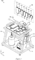
- FIG. 1 shows a perspective view of a sample treating device 1000 according to an embodiment of the present invention.
- the sample treating device 1000 comprises at least a treatment section 100 for treating a sample, a controller 200 for controlling operations of the treatment section 100, and a solution supply section 300 provided above the treatment section 100.
- the sample treating device 1000 preferably comprises any one or more of the followings: a liquid waste tank 400 provided beneath the treatment section 100; a biological substance storage section 500 provided beneath the treatment section 100; a CO 2 gas supply unit (CO 2 gas cylinder) 600 provided beneath the treatment section 100; and a housing 700 for accommodating at least the treatment section 100.
- CO 2 gas supply unit CO 2 gas cylinder
- the treatment section 100 comprises a generally flat treating stage 110 and two rotation shafts 810 and 820 ( Figure 2 ).
- the flat treating stage 110 is shown in a substantially horizontal state.
- the treatment section 100 performs treatments by tilting each of units (bag or container) mounted on and secured to the substantially horizontal treating stage in multiple directions using the two rotation shafts 810 and 820.
- the units of the treatment section 100 are connected to bags or the like of the solution supply section 300 arranged above the treatment section 100.
- Each of the tubes is provided with a valve whose opening/closing is controlled by the controller 200.
- a pinch valve is used as the valve, where the pinch valve can close the tube by pinching the flexible tube from outside.
- the tube is a silicone tube.
- the housing 700 can accommodate any one or more of the followings: a controller (for example, personal computer) 200; a solution supply section 300; a liquid waste tank 400; a biological substance storage section 500; and a CO 2 gas supply unit 600.
- the housing 700 is provided with a window 710 made of glass or a transparent resin so that the states of the treatment section 100 and the solution supply section 300 can be visually observed through the window 710.
- FIG 2 is a upper perspective view of the sample treating device 1000 shown in Figure 1 with the housing 700 being omitted.
- the solution supply section 300 preferably includes any one or more of the followings: a whole blood-containing bag (sample container) 310; a magnetic bead solution bag (magnetic bead solution container) 320; a separating agent solution bag (reagent solution container) 330; a first wash solution bag (first wash solution container) 340; a second wash solution bag (second wash solution container) 350; a culture reagent solution bag (culture reagent solution container) 360; and a culture solution bag (culture solution container) 370.
- an air venting needle (aeration needle) is preferably stuck into the bag to promote the solution in the bag to fall.
- the vent of the air venting needle is provided with a filter.
- the container is preferably provided with a vent with a lid.
- the lid is preferably loosened to allow ventilation via the vent to promote the solution inside the container to fall.
- the vent of the container is provided with a filter.
- the solution supply section 300 is preferably provided with a bellows (solution pressurizer) 380 shown in Figure 1 .
- the bellows 380 is preferably compressed (pressed) by an actuator (not shown) to apply a pressure to a filter unit 130 described below to transfer the solution.
- a CO 2 gas supply unit 600 may favorably be used as a solution pressurizer instead of the bellows.
- Each of the bags 310-370 and/or the bellows 380 is preferably made of a flexible resin and provided with a hang tab on the top.
- This tab can be hanged on a hook or the like provided inside the housing 700 so that the bags 310-370 and/or the bellows 380 can be kept at positions higher than the treatment section 100 within the housing 700.
- tubes connecting the bags and the bellows 380 of the solution supply section 300 with the treatment section 100 are omitted.
- the biological substance storage section 500 is preferably provided with either or both of a storage bag (storage container) 510 and a cooler (e.g., Peltier device) 520 for cooling the storage bag 510.
- the tube connecting the biological substance storage section 500 and the treatment section 100 (culture unit 140 described below) is preferably provided with a magnetic force unit 900.
- a minute amount of magnetic particles may be remaining in the solution containing the biological substance which is transferred from the treatment section 100 to the biological substance storage section 500 by the fall thereof.
- the magnetic force unit 900 exerts a magnetic force on the solution containing the biological substance that has been treated at the treatment section 100. If a minute amount of magnetic particles is contained in the solution, these magnetic particles can be adsorbed by the magnetic force.
- the treatment section 100 comprises a frame 104, a treating stage 110 rotatably held by the frame 104, a cell separating unit (biological substance separating unit) 120 detachably disposed on the treating stage 110, a filter unit (filtering section) 130 detachably disposed on the treating stage 110, and a culture unit (manipulation unit) 140 detachably disposed on the treating stage 110.
- a whole blood-containing bag 310, a magnetic bead solution bag 320, a separating agent solution bag 330 and a first a wash solution bag 340 are connected to the cell separating unit 120 via tubes so that the solution in each bag can flow into the cell separating unit 120.
- the treating stage 110 is a generally flat plate member. In Figures 2-4 , the flat surface of the treating stage 110 is shown in a substantially horizontal standby state.
- the filter unit 130 is preferably disposed adjacent to the cell separating unit 120 in the x-direction.
- the filter unit 130 comprises a first chamber 132 connected to the cell separating unit 120 in the x-direction via a tube, a filter section 134 connected to the first chamber 132 in the x-direction, and a second chamber 136 connected to the filter section 134 in the x-direction.
- the first chamber 132, the filter chamber 134 and the second chamber 136 are disposed along the x-direction (the first rotation shaft 810).
- a second wash solution bag 350 is connected via a tube.
- a culture reagent solution bag 360, a culture solution bag 370 and a bellows 380 are connected via tubes.
- the filter section 134 is provided with a filter or a dialysis membrane for filtering the biological substance.
- the culture unit 140 is disposed adjacent to the first chamber 132 of the filter unit 130 in the y-direction, and connected to the first chamber 132 via a tube.
- the liquid waste tank 400 for receiving the liquid waste from each unit, the biological substance storage section 500 for storing the biological substance obtained by the treatment, and the CO 2 gas supply unit 600 are connected via tubes.
- the sample treating device 1000 is preferably provided with a pair of supports 720 and 730 for supporting the treatment section 100 on the bottom frame 715 of the housing 700.
- the sample treating device 1000 is provided with a first rotation shaft 810 extending in the x-direction, a first motor (first driver) 812 for rotating the first rotation shaft 810, and a drive belt 814 for transmitting rotation of the first motor 812 to the first rotation shaft 810. Both ends of the first rotation shaft 810 are rotatably supported by the pair of supports 720 and 730.
- the first motor 812 is fixed to the support 720.
- the treatment section 100 is fixed to the first rotation shaft 810. Accordingly, the treatment section 100 rotates integrally with the first rotation shaft 810.
- the units and members provided on the upper and bottom surfaces of the treating stage 110 are not shown.
- the sample treating device 1000 is provided with a second rotation shaft 820 extending in the y-direction, a second motor (second driver) 822 for rotating the second rotation shaft 820, and a drive belt 824 for transmitting rotation of the second motor 822 to the second rotation shaft 820.
- Both ends of the second rotation shaft 820 are rotatably supported by the frame 104.
- the second motor 822 is fixed to the frame 140.
- the treating stage 110 is fixed to the second rotation shaft 820. Accordingly, the treating stage 110 rotates integrally with the second rotation shaft 820.
- the axial direction of the first rotation shaft 810 is arranged in a direction different from the axial direction of the second rotation shaft 820 or in a direction intersecting the axial direction of the second rotation shaft 820. More preferably, the axial direction of the first rotation shaft 810 is arranged in a direction that makes an angle of about 90 degrees with the axial direction of the second rotation shaft 820.
- the bottom surface of the treatment section 100 is preferably provided with any one or more of the followings: a magnetic force-exerting unit 150 for exerting a magnetic force inside the cell separating unit 120; a temperature regulating unit 160 for regulating the temperature inside the culture unit 140 to a temperature suitable for a treatment such as culture; and a valve actuator (solenoid) 170 for actuating each of the valves that open and close the tubes.
- a magnetic force-exerting unit 150 for exerting a magnetic force inside the cell separating unit 120
- a temperature regulating unit 160 for regulating the temperature inside the culture unit 140 to a temperature suitable for a treatment such as culture
- a valve actuator (solenoid) 170 for actuating each of the valves that open and close the tubes.
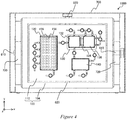
- the magnetic force-exerting unit 150 is provided with a plurality of lifting shafts 154 extending downward (in the z-direction) from the bottom surface of the treatment section 100, a magnet plate (permanent magnet) 155 that moves toward and away (in the z-direction) from the bottom surface of the cell separating unit 120 while facing said bottom surface, a magnet arrangement area 156 provided within the magnet plate 155 ( Figure 4 ), and a third motor (third driver) 152 for driving the magnet plate 155.
- the operation of the third motor (third driver) 152 is controlled by the controller 200.
- the magnet plate 155 and the third motor 152 form a magnetic force-controlling mechanism.
- the magnetic force-exerting unit 150 can be composed of an electromagnet. In this case, the magnetic force of the electromagnet is controlled by the controller 200.
- a plurality of permanent magnets 158 are evenly arranged in the magnet arrangement area 156.
- the permanent magnets can preferably be arranged such that adjacent permanent magnets have different polarities.
- the biological substance e.g., cells
- the magnetic beads are coupled to an antibody for the specific biological substance contained in the sample.
- specific biological substance may be, for example, a protein, a cell, nucleic acids (RNA or DNA), an exosome or the like.
- the bags of the solution supply section 300, the units on the treating stage 100 and the tubes are preferably sterilized in advance, and they can be exchanged or disposed after the sample treatment is completed.
- each unit arranged on the upper surface of the treating stage 110 of the treatment section 100 may have a sealed structure and the sample treating steps can be automated. By doing so, the treatment can be carried out without a manual operation, which can reduce the possibility of contamination.
- the sample treating device can be used to automatically take out cells of interest including a cancer cell or the like (for example, erythrocytes, leukemia cells or circulating tumor cells (CTC)), a human leukocyte antigen (HLA), exosomes or nucleic acids such as microRNA from a large amount (several hundred ml) of sample such as whole blood.
- a cancer cell or the like for example, erythrocytes, leukemia cells or circulating tumor cells (CTC)
- HLA human leukocyte antigen
- exosomes or nucleic acids such as microRNA from a large amount (several hundred ml) of sample such as whole blood.
- the culture unit 140 is preferably used as a mixing or manipulation unit for mixing with a biological substance-detecting reagent (labeled antibody) or for manipulating therewith, and the biological substance storage section 500 can be provided with a measurement mechanism for measuring the biological substance bound to the labeled antibody.
- the measurement mechanism of the biological substance storage section 500 can be used for detecting and quantifying the biological substance and the like.
- This measurement mechanism may be composed of, for example, a light-transmitting optical fiber for transmitting excitation light from a light source to the storage bag 510, a light-collecting optical fiber for collecting fluorescent light emitted from the labeled antibody irradiated with the light, and a detection element for detecting fluorescent light from the light-collecting optical fiber.
- the treatment time spent for obtaining a biological substance of interest from a sample can be relatively long, for example, preferably 12 hours to about 36 hours, more preferably 20 hours to 28 hours, and still more preferably about 24 hours so that no stress is applied to the delicate biological substance.
- the CO 2 gas supply unit 600 can be connected to a predetermined unit to apply a relatively low pressure to said unit so as to promote delivery of the solution in the tilted predetermined unit.
- the predetermined unit may be, for example, the cell separating unit 120, the filter unit 130 or the culture unit 140.
- the angle of the treatment section 100 (frame 104) tilted by the first rotation shaft 810 and/or the angle of the treating stage 110 tilted by the second rotation shaft 820 is preferably in a range of 0-180 degrees and more preferably in a range of 0-90 degrees, and can be varied according to the specific treatment.
- a treatment operation using the sample treating device 1000 of this embodiment will be described, in which cells of interest such as immune cells (biological substance) are separated (isolated) from human whole blood (sample), and highly active cells of interest such as more active immune cells are obtained from the separated cells of interest by culture or the like.
- cells of interest such as immune cells (biological substance) are separated (isolated) from human whole blood (sample)
- highly active cells of interest such as more active immune cells are obtained from the separated cells of interest by culture or the like.
- a step of supplying solutions to the cell separating unit 120 is performed.
- the valve provided on each of the tubes is opened in response to the command from the controller 200.
- the whole blood (for example, 200 ml or 400 ml) in the whole blood-containing bag 310 is transferred to the cell separating unit 120 by the fall thereof via the tube.
- the magnetic bead solution (for example, 50 ml) in the magnetic bead solution bag 320 is transferred to the cell separating unit 120 by the fall thereof via the tube.
- the separating agent solution (for example, 200 ml) in the separating agent solution bag 330 is transferred to the cell separating unit 120 by the fall thereof via the tube.
- the controller 200 directs a mixing step for mixing the solutions supplied to the cell separating unit 120.
- the controller 200 drives the first motor 812 for a predetermined period of time to rotate the first rotation shaft 810 clockwise and anti-clockwise alternately within a predetermined angle range so as to swing the treatment section 100.
- the predetermined angle range may be, for example a range of ⁇ 15 to ⁇ 30 degrees with respect to the horizontal state.
- the controller 200 may also drive the second motor 822 instead of the first motor 812 for a predetermined period of time to rotate the second rotation shaft 820 clockwise and anti-clockwise alternately within a predetermined angle range so as to swing the treating stage 110. Furthermore, the first motor 812 and the second motor 822 can be driven simultaneously to perform complicated shaking operations.
- the controller 200 performs a cell adsorbing step. After turning off the first motor 812 and the second motor 822 when the frame 104 and the treating stage 110 of the treatment section 100 are in the horizontal state, the controller 200 elevates the magnet plate 155 to the adsorbing position where the magnet plate 155 is positioned in the vicinity of or to make contact with the bottom surface of the cell separating unit 120. At the adsorbing position, the plurality of permanent magnets 158 in the magnet arrangement area 156 exert magnetic force on the magnetic beads in the cell separating unit 120.
- the cells of interest in the solution in the cell separating unit 120 are attached to magnetic beads coupled to an antibody for the cell of interest, when the magnet plate 155 is transferred to the adsorbing position, the cells of interest contained in the solution move towards and adsorbed by the plurality of magnets 158 shown in Figure 4 .
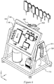
- the controller 200 performs a liquid waste disposal step. While the cells of interest are adsorbed to the plurality of magnets, the controller 200 tilts the treatment section 100 at a predetermined angle as shown in Figure 6 .
- the predetermined angle may be, for example, 60-90 degrees with respect to the horizontal state.
- the valve of the tube connecting the cell separating unit 120 and the liquid waste tank 400 is opened for a predetermined period of time so that the unnecessary solution other than the cells having the magnetic particles attached thereto is transferred to the liquid waste tank 400 by the fall thereof via the tube.
- the controller 200 closes the valve of the tube connecting the cell separating unit 120 and the liquid waste tank 400, and moves the treatment section 100 to the horizontal position, thereby completing the liquid waste disposal step.
- the controller 200 performs a wash solution supplying step.
- the controller 200 opens the valve of the tube connecting the wash solution bag 340 and the cell separating unit 120 so that the wash solution in the wash solution bag 340 is transferred to the cell separating unit 120 by the fall thereof.
- the controller 200 After the wash solution supplying step is completed, the controller 200 performs a washing step. In the washing step, the controller 200 lowers the magnet plate 155 and swings the cell separating unit 120 in the same motion as in the mixing step while the magnetic force is not transmitted to the cell separating unit 120, thereby mixing the cells of interest having the magnetic beads attached thereto and the wash solution for a predetermined period of time in the cell separating unit 120. Once the cells of interest and the wash solution are sufficiently mixed, the magnetic beads are separated from the cells of interest, thereby completing the washing step.
- the controller 200 performs a magnetic bead-separating step.
- the controller 200 positions the treatment section 100 to be in the horizontal state and then elevates the magnet plate 155 to the adsorbing position where the magnet plate 155 is positioned in the vicinity of the bottom surface of the cell separating unit 120.
- the magnetic beads are transferred towards and adsorbed by the plurality of magnets 158 shown in Figure 4 , but the cells of interest separated from the magnetic beads are dispersed in the solution.
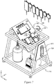
- the treating stage 110 is tilted at a predetermined angle as shown in Figure 7 .
- the predetermined angle may be, for example, 45-90 degrees with respect to the horizontal state.
- the valve of the tube connecting the cell separating unit 120 and the filter unit 130 is opened for a predetermined period of time so that the solution containing the cells of interest but not the magnetic beads is transferred to the filter unit 130 by the fall thereof via the tube.
- the treating stage is moved to the horizontal state ( Figure 2 ), thereby completing the magnetic bead-separating step.
- the controller 200 performs a washing step for washing the extracted cells of interest.
- the controller 200 opens the valve of the tube connecting the second wash solution bag 350 and the first chamber 132 to transfer the wash solution in the second wash solution bag 350 to the first chamber 132 by the fall thereof via the tube.
- the controller 200 also opens the valve of the tube connecting the second chamber 136 and the liquid waste tank 400.
- the wash solution in the second wash solution bag 350 flows through the first chamber 132, the filter chamber 134 and the second chamber 136 in this order to be transferred to the liquid waste tank 400 by the fall thereof.
- the wash solution flows through the filter section 134, the cells of interest held at the filter section 134 are washed, thereby removing unnecessary substances from the cells of interest.
- the controller 200 closes the valve of the tube connecting the second chamber 136 and the liquid waste tank 400 and opens the valve of the tube connecting the first chamber 132 and the culture unit 140, thereby proceeding to the culture preparation step.
- the controller 200 opens the valve of the tube connecting the culture reagent solution bag 360 and the second chamber 136 and opens the valve of the tube connecting the culture solution bag 370 and the second chamber 136. By doing so, the culture reagent solution in the culture reagent solution bag 360 and the culture solution in the culture solution bag 370 are transferred to the second chamber 136 by the fall thereof.
- the culture reagent solution that fell from the culture reagent solution bag 360 and the culture solution that fell from the culture solution bag 370 flow through the second chamber 136, the filter section 134, the first chamber 132 and the tube connecting the first chamber 132 and the culture unit 140 to be transferred to the culture unit 140.
- the culture reagent solution and the culture solution flow through the filter section 134, the cells of interest trapped at the filter section 134 are transferred to the culture unit 140 together with the culture reagent solution and the culture solution.
- the bellows 380 may preferably be compressed to apply a pressure to the second chamber 136 to forcibly separate the cells of interest from the filter section 134.
- the treatment section 100 can preferably be tilted as shown in Figure 6 to promote the solution transfer.
- the valve of the tube connecting the culture unit 140 and the filter unit 130 is closed to proceed to the culture step.
- a pressure can be applied to the second chamber 136 by utilizing a pressure of CO 2 supplied from the CO 2 gas supply unit 600.
- the controller 200 performs culture of the cells of interest which have been mixed with the culture reagent and the culture solution while maintaining a suitable temperature inside the culture unit 140 using the temperature regulating unit 160, and supplying CO 2 from the CO 2 gas supply unit 600. Furthermore, while performing the culture, the treating stage 100 and/or the entire treatment section 100 can be swung in the same motion as in the mixing step.
- the treatment section 100 is tilted to the state shown in Figure 6 and the valve of the tube connecting the culture unit 140 and the liquid waste tank 400 is opened, so that the solution containing the cultured highly active cells of interest is transferred to the storage bag 510 of the biological substance storage section 500 by the fall thereof. While the solution containing the cultured highly active cells of interest is kept in the storage bag 510, the storage bag 510 is cooled by the cooler 520.
Landscapes
- Chemical & Material Sciences (AREA)
- Health & Medical Sciences (AREA)
- Engineering & Computer Science (AREA)
- Life Sciences & Earth Sciences (AREA)
- Zoology (AREA)
- Wood Science & Technology (AREA)
- Bioinformatics & Cheminformatics (AREA)
- Organic Chemistry (AREA)
- Biotechnology (AREA)
- Microbiology (AREA)
- Genetics & Genomics (AREA)
- Biomedical Technology (AREA)
- Sustainable Development (AREA)
- Biochemistry (AREA)
- General Engineering & Computer Science (AREA)
- General Health & Medical Sciences (AREA)
- Analytical Chemistry (AREA)
- Computer Hardware Design (AREA)
- Clinical Laboratory Science (AREA)
- Molecular Biology (AREA)
- Apparatus Associated With Microorganisms And Enzymes (AREA)
- Filtration Of Liquid (AREA)
- Mixers With Rotating Receptacles And Mixers With Vibration Mechanisms (AREA)
- Accessories For Mixers (AREA)
Applications Claiming Priority (2)
| Application Number | Priority Date | Filing Date | Title |
|---|---|---|---|
| JP2019018830 | 2019-02-05 | ||
| PCT/JP2020/004054 WO2020162431A1 (fr) | 2019-02-05 | 2020-02-04 | Dispositif de traitement d'échantillon |
Publications (2)
| Publication Number | Publication Date |
|---|---|
| EP3922711A1 true EP3922711A1 (fr) | 2021-12-15 |
| EP3922711A4 EP3922711A4 (fr) | 2022-11-30 |
Family
ID=71947716
Family Applications (1)
| Application Number | Title | Priority Date | Filing Date |
|---|---|---|---|
| EP20752716.9A Pending EP3922711A4 (fr) | 2019-02-05 | 2020-02-04 | Dispositif de traitement d'échantillon |
Country Status (4)
| Country | Link |
|---|---|
| US (1) | US20220119752A1 (fr) |
| EP (1) | EP3922711A4 (fr) |
| JP (1) | JP7458573B2 (fr) |
| WO (1) | WO2020162431A1 (fr) |
Families Citing this family (3)
| Publication number | Priority date | Publication date | Assignee | Title |
|---|---|---|---|---|
| EP4226163B1 (fr) * | 2020-10-12 | 2025-12-24 | Life Technologies AS | Systèmes de traitement de particules magnétiques destinés à être utilisés avec des cellules biologiques et procédés associés |
| JP7659245B2 (ja) * | 2021-07-26 | 2025-04-09 | ユニバーサル・バイオ・リサーチ株式会社 | 生体関連物質の抽出装置及び処理システム |
| WO2025106534A1 (fr) * | 2023-11-15 | 2025-05-22 | Flaskworks, Llc | Instrument de traitement pour la fabrication de thérapie cellulaire |
Family Cites Families (13)
| Publication number | Priority date | Publication date | Assignee | Title |
|---|---|---|---|---|
| US6036857A (en) * | 1998-02-20 | 2000-03-14 | Florida State University Research Foundation, Inc. | Apparatus for continuous magnetic separation of components from a mixture |
| US7585670B2 (en) * | 2001-12-07 | 2009-09-08 | Cytori Therapeutics, Inc. | Automated methods for isolating and using clinically safe adipose derived regenerative cells |
| JP4594029B2 (ja) * | 2004-10-13 | 2010-12-08 | テルモ株式会社 | 血液成分採取装置 |
| US20080291456A1 (en) * | 2007-05-24 | 2008-11-27 | Ghislain Lucien P | Sensor apparatus and method using optical interferometry |
| JP4445993B2 (ja) * | 2007-11-27 | 2010-04-07 | 株式会社日立製作所 | 細胞培養装置 |
| JP6057214B2 (ja) * | 2013-06-03 | 2017-01-11 | 株式会社日立製作所 | 培養容器、培養システム及び培養装置 |
| EP3020798A4 (fr) | 2013-07-09 | 2017-02-08 | Universal Bio Research Co., Ltd. | Dispositif de culture, système de culture et procédé de culture |
| US10676707B2 (en) * | 2013-09-12 | 2020-06-09 | Universal Bio Research Co., Ltd. | Culture system and culture method |
| JP6424447B2 (ja) * | 2014-03-28 | 2018-11-21 | 東洋製罐グループホールディングス株式会社 | 細胞培養方法、及び細胞培養システム |
| AU2016205090A1 (en) * | 2015-01-09 | 2017-07-27 | Aviva Biosciences Corporation | Methods and devices for breaking cell aggregation and separating or enriching cells |
| JP6768002B2 (ja) * | 2015-12-28 | 2020-10-14 | Phcホールディングス株式会社 | 試料分析用基板、試料分析装置、試料分析システムおよび試料分析システム用プログラム |
| TWI616526B (zh) * | 2017-05-15 | 2018-03-01 | Cell separation and purification device | |
| JP6878163B2 (ja) * | 2017-06-15 | 2021-05-26 | 株式会社京都製作所 | 培養装置および培養方法 |
-
2020
- 2020-02-04 EP EP20752716.9A patent/EP3922711A4/fr active Pending
- 2020-02-04 US US17/428,033 patent/US20220119752A1/en not_active Abandoned
- 2020-02-04 JP JP2020571202A patent/JP7458573B2/ja active Active
- 2020-02-04 WO PCT/JP2020/004054 patent/WO2020162431A1/fr not_active Ceased
Also Published As
| Publication number | Publication date |
|---|---|
| JPWO2020162431A1 (ja) | 2021-12-09 |
| EP3922711A4 (fr) | 2022-11-30 |
| WO2020162431A1 (fr) | 2020-08-13 |
| US20220119752A1 (en) | 2022-04-21 |
| JP7458573B2 (ja) | 2024-04-01 |
Similar Documents
| Publication | Publication Date | Title |
|---|---|---|
| JP3630493B2 (ja) | 分注機を利用した液体処理方法およびその装置 | |
| US6673595B2 (en) | Automated cell management system for growth and manipulation of cultured cells | |
| JP3551293B2 (ja) | 核酸抽出装置 | |
| JP4074058B2 (ja) | 流体試料と粒子物質を混合および流体試料から粒子物質を分離をする方法、およびその装置 | |
| US20220119752A1 (en) | Sample treating device | |
| JP5998218B2 (ja) | 磁力体カバー及び核酸抽出装置 | |
| CN111989390B (zh) | 用于从样品提取生物分子的系统及相关方法 | |
| JP4643008B2 (ja) | 磁性粒子を利用した濃縮装置およびその方法 | |
| EP3020798A1 (fr) | Dispositif de culture, système de culture et procédé de culture | |
| KR20010023340A (ko) | 유체 시료로부터 분리된 입자성 물질의 단층을자동형성하기 위한 방법 및 장치 | |
| JPWO2000042410A1 (ja) | 磁性粒子を利用した濃縮装置およびその方法 | |
| EP1491623A1 (fr) | Incubateur et dispositif de culture | |
| US20240392230A1 (en) | Apparatus and process for the automated manufacturing of genetically engineered cells from biological fluids | |
| CN110167673B (zh) | 培养设备以及包括培养设备和摇摆台的系统 | |
| US6830935B1 (en) | Method for mixing and processing specimen samples | |
| JP2020534517A (ja) | 試料の減容のための方法および装置 | |
| EP1093572B1 (fr) | Procede ameliore de melange et de traitement d'echantillons | |
| WO2023008270A1 (fr) | Dispositif d'extraction de substance biologique et système de traitement | |
| EP4277975A1 (fr) | Systèmes et procédés pour le traitement de cellules | |
| US20250303031A1 (en) | Closed automated system and method for multiplex cell processing | |
| KR100211129B1 (ko) | 분주기를 이용한 액체처리방법 및 그 장치 | |
| KR20260063048A (ko) | 연구 및 의료용 실험 장치 콤비셀 | |
| WO2025207088A1 (fr) | Système automatisé fermé et procédé de traitement de cellules multiplex | |
| WO2004048564A1 (fr) | Dispositif de pretraitement d'echantillon | |
| JPWO2002042430A1 (ja) | 核酸抽出装置 |
Legal Events
| Date | Code | Title | Description |
|---|---|---|---|
| STAA | Information on the status of an ep patent application or granted ep patent |
Free format text: STATUS: THE INTERNATIONAL PUBLICATION HAS BEEN MADE |
|
| PUAI | Public reference made under article 153(3) epc to a published international application that has entered the european phase |
Free format text: ORIGINAL CODE: 0009012 |
|
| STAA | Information on the status of an ep patent application or granted ep patent |
Free format text: STATUS: REQUEST FOR EXAMINATION WAS MADE |
|
| 17P | Request for examination filed |
Effective date: 20210730 |
|
| AK | Designated contracting states |
Kind code of ref document: A1 Designated state(s): AL AT BE BG CH CY CZ DE DK EE ES FI FR GB GR HR HU IE IS IT LI LT LU LV MC MK MT NL NO PL PT RO RS SE SI SK SM TR |
|
| DAV | Request for validation of the european patent (deleted) | ||
| DAX | Request for extension of the european patent (deleted) | ||
| A4 | Supplementary search report drawn up and despatched |
Effective date: 20221103 |
|
| RIC1 | Information provided on ipc code assigned before grant |
Ipc: C12M 1/00 20060101ALI20221027BHEP Ipc: C12M 1/36 20060101ALI20221027BHEP Ipc: B03C 1/00 20060101ALI20221027BHEP Ipc: C12M 3/08 20060101ALI20221027BHEP Ipc: C12M 3/06 20060101ALI20221027BHEP Ipc: C12M 3/00 20060101AFI20221027BHEP |