EP3922845B1 - Ouvrage en mer flottant et son procédé d'installation - Google Patents
Ouvrage en mer flottant et son procédé d'installation Download PDFInfo
- Publication number
- EP3922845B1 EP3922845B1 EP21177294.2A EP21177294A EP3922845B1 EP 3922845 B1 EP3922845 B1 EP 3922845B1 EP 21177294 A EP21177294 A EP 21177294A EP 3922845 B1 EP3922845 B1 EP 3922845B1
- Authority
- EP
- European Patent Office
- Prior art keywords
- offshore structure
- base body
- floating offshore
- structure according
- floating
- Prior art date
- Legal status (The legal status is an assumption and is not a legal conclusion. Google has not performed a legal analysis and makes no representation as to the accuracy of the status listed.)
- Active
Links
Images



Classifications
-
- F—MECHANICAL ENGINEERING; LIGHTING; HEATING; WEAPONS; BLASTING
- F03—MACHINES OR ENGINES FOR LIQUIDS; WIND, SPRING, OR WEIGHT MOTORS; PRODUCING MECHANICAL POWER OR A REACTIVE PROPULSIVE THRUST, NOT OTHERWISE PROVIDED FOR
- F03D—WIND MOTORS
- F03D13/00—Assembly, mounting or commissioning of wind motors; Arrangements specially adapted for transporting wind motor components
- F03D13/20—Arrangements for mounting or supporting wind motors; Masts or towers for wind motors
- F03D13/25—Arrangements for mounting or supporting wind motors; Masts or towers for wind motors specially adapted for offshore installation
-
- B—PERFORMING OPERATIONS; TRANSPORTING
- B63—SHIPS OR OTHER WATERBORNE VESSELS; RELATED EQUIPMENT
- B63B—SHIPS OR OTHER WATERBORNE VESSELS; EQUIPMENT FOR SHIPPING
- B63B35/00—Vessels or similar floating structures specially adapted for specific purposes and not otherwise provided for
- B63B35/44—Floating buildings, stores, drilling platforms, or workshops, e.g. carrying water-oil separating devices
- B63B2035/4433—Floating structures carrying electric power plants
-
- B—PERFORMING OPERATIONS; TRANSPORTING
- B63—SHIPS OR OTHER WATERBORNE VESSELS; RELATED EQUIPMENT
- B63B—SHIPS OR OTHER WATERBORNE VESSELS; EQUIPMENT FOR SHIPPING
- B63B35/00—Vessels or similar floating structures specially adapted for specific purposes and not otherwise provided for
- B63B35/44—Floating buildings, stores, drilling platforms, or workshops, e.g. carrying water-oil separating devices
- B63B2035/4433—Floating structures carrying electric power plants
- B63B2035/446—Floating structures carrying electric power plants for converting wind energy into electric energy
-
- F—MECHANICAL ENGINEERING; LIGHTING; HEATING; WEAPONS; BLASTING
- F05—INDEXING SCHEMES RELATING TO ENGINES OR PUMPS IN VARIOUS SUBCLASSES OF CLASSES F01-F04
- F05B—INDEXING SCHEME RELATING TO WIND, SPRING, WEIGHT, INERTIA OR LIKE MOTORS, TO MACHINES OR ENGINES FOR LIQUIDS COVERED BY SUBCLASSES F03B, F03D AND F03G
- F05B2240/00—Components
- F05B2240/90—Mounting on supporting structures or systems
- F05B2240/95—Mounting on supporting structures or systems offshore
-
- F—MECHANICAL ENGINEERING; LIGHTING; HEATING; WEAPONS; BLASTING
- F05—INDEXING SCHEMES RELATING TO ENGINES OR PUMPS IN VARIOUS SUBCLASSES OF CLASSES F01-F04
- F05B—INDEXING SCHEME RELATING TO WIND, SPRING, WEIGHT, INERTIA OR LIKE MOTORS, TO MACHINES OR ENGINES FOR LIQUIDS COVERED BY SUBCLASSES F03B, F03D AND F03G
- F05B2240/00—Components
- F05B2240/90—Mounting on supporting structures or systems
- F05B2240/97—Mounting on supporting structures or systems on a submerged structure
-
- Y—GENERAL TAGGING OF NEW TECHNOLOGICAL DEVELOPMENTS; GENERAL TAGGING OF CROSS-SECTIONAL TECHNOLOGIES SPANNING OVER SEVERAL SECTIONS OF THE IPC; TECHNICAL SUBJECTS COVERED BY FORMER USPC CROSS-REFERENCE ART COLLECTIONS [XRACs] AND DIGESTS
- Y02—TECHNOLOGIES OR APPLICATIONS FOR MITIGATION OR ADAPTATION AGAINST CLIMATE CHANGE
- Y02E—REDUCTION OF GREENHOUSE GAS [GHG] EMISSIONS, RELATED TO ENERGY GENERATION, TRANSMISSION OR DISTRIBUTION
- Y02E10/00—Energy generation through renewable energy sources
- Y02E10/70—Wind energy
- Y02E10/72—Wind turbines with rotation axis in wind direction
-
- Y—GENERAL TAGGING OF NEW TECHNOLOGICAL DEVELOPMENTS; GENERAL TAGGING OF CROSS-SECTIONAL TECHNOLOGIES SPANNING OVER SEVERAL SECTIONS OF THE IPC; TECHNICAL SUBJECTS COVERED BY FORMER USPC CROSS-REFERENCE ART COLLECTIONS [XRACs] AND DIGESTS
- Y02—TECHNOLOGIES OR APPLICATIONS FOR MITIGATION OR ADAPTATION AGAINST CLIMATE CHANGE
- Y02E—REDUCTION OF GREENHOUSE GAS [GHG] EMISSIONS, RELATED TO ENERGY GENERATION, TRANSMISSION OR DISTRIBUTION
- Y02E10/00—Energy generation through renewable energy sources
- Y02E10/70—Wind energy
- Y02E10/727—Offshore wind turbines
Definitions
- the invention relates to a floating offshore structure according to the preamble of claim 1 and a method for installing the floating offshore structure.
- a floating wind turbine which has a supporting unit which is designed as a semi-submersible with a ballast unit and a buoyancy unit.
- the wind turbine is firmly connected to the supporting unit with a supporting mast.
- the US7,281,881 B1 reveals a floating oil or gas platform with three lateral column-shaped buoyancy bodies.
- a wind turbine with a buoyancy unit is known, with three lateral column-like ballasting tanks, which are connected to each other by a rod, on which a wind turbine is positioned in the middle.
- the FR3051022 describes a wind turbine that is centrally mounted on a three-legged base, from which three cylindrical buoyancy bodies extend upwards.
- the EP 2 479 103 A1 relates to a wind turbine with tetrahedral arranged, column-shaped buoyancy bodies, which are kept at a distance from each other by a rod system on the ground.
- a floating wind turbine is designed with a triangular rod foundation from which three ballasting tanks extend upwards. These are in turn connected to a tower of the wind turbine via a rod.
- the WO 2018/174348A1 reveals a floating wind turbine on a buoyancy body with lateral inclined supports.
- the object of the present invention is to provide a floating offshore structure which avoids, or at least reduces, the above-mentioned disadvantages, and to provide a method for installing this offshore structure.
- the floating offshore structure comprises a foundation and a superstructure.
- the superstructure is designed in particular as a wind turbine, with a tower, a machine house and a rotor or as a substation.
- the foundation comprises a coherent base body with at least one ballasting tank.
- Support legs extend from the base body and lead to a transition piece on which the superstructure, in particular the wind turbine, is arranged.
- the support legs comprise at least two support tubes running next to each other, at least in sections. According to the invention, the at least two support tubes running next to each other run parallel to each other.
- the offshore structure is designed to float in a weight-stable manner in an operating position.
- the invention makes use of the idea of arranging a superstructure on a foundation, whereby the foundation generates buoyancy that keeps both the foundation and the superstructure floating in place.
- the foundation comprises a base body with ballasting tanks, which are preferably located at the very bottom of the foundation on the seabed side. are arranged so that support legs extend from the base body towards a transition piece on which the superstructure is arranged. The support legs are arranged between the base body and the transition piece.
- the very deep ballasting tanks also have the advantage that the draught of the offshore structure is very low when the ballasting tanks are filled with air and, on the other hand, when at least one ballasting tank is filled with water, the center of gravity is very low.
- the fact that the support legs are formed in sections by two support leg tubes running next to each other creates a redundancy that ensures the stability of the entire offshore structure even in the event of a collision with a ship or damage to one of the support leg tubes.
- Weight-stable floating here means that in the operating position the centre of buoyancy is preferably arranged exactly vertically above the centre of mass of the floating offshore structure and that in the event of tipping movements, in particular tilting, of the offshore structure, an uprighting lever arm is usually formed which generates a restoring force and moves the offshore structure back to the operating position.
- the offshore structure is designed to be free-floating.
- Free-floating here means that there are no tensile anchors that prevent the offshore structure from moving up and down.
- the platform according to the invention can follow the sea.
- the offshore structure is not constantly pulled against the seabed under tensile stress.
- Loose anchors are possible, which can only limit or prevent drifting or rotational movements of the offshore structure.
- the loose anchor does not generate any additional tensile stress through the anchor cable to the seabed.
- Loose anchors with two, three or more anchors and anchor cables are also possible.
- the buoyancy force corresponds to the gravity of the offshore structure.
- the buoyancy force corresponds to the gravity plus the vertical tensile stress through the tensioned anchor cables.
- the at least two support leg tubes run parallel to each other, the at least two support leg tubes running next to each other can be rigidly connected to each other via oblique connections.
- the connections can be designed as connecting pipes, which are preferably mounted on the outside of the support leg tubes, preferably welded on.
- the support legs can also be formed by three, four or an even higher number of pipes running next to each other. These pipes also preferably all run parallel to each other.
- the entire offshore structure has at least three of these support leg pairs or support leg bundles, each of which extends from the transition piece to the base body and firmly connects the transition piece to the base body, so that the support legs are each arranged between the base body and the transition piece.
- At least two support leg tubes means two, three or any higher number.
- all distances between support leg tubes of a support leg are smaller than all distances between support leg tubes of different support legs.
- the support leg tubes of a support leg form a group of support leg tubes that are close to one another. The distance is preferably determined in the horizontal plane.
- At least one of the support legs has a hollow body in sections, from at least one side of which the at least two support leg tubes extend next to one another.
- the support leg thus has, for example, a cylindrical or cubic hollow body in sections along its longitudinal direction, from one end face of which arranged in the longitudinal direction and possibly also from its other opposite end face arranged in the longitudinal direction, the at least two support leg tubes extend.
- the support leg tubes can then lead to the transition piece on the one hand and to the base body on the other and be connected to them in each case. It is also conceivable that further hollow bodies are provided along the support leg, with two hollow bodies then being firmly connected to one another with two or a higher number of support leg tubes and at least two support leg tubes being connected to the transition piece or to the base body.
- the base body preferably has a polygonal outer circumference in a plan view, at the corners of which the support legs are mounted.
- the base body is preferably designed as a hollow body, in the interior of which a ballasting tank, but preferably two, three or any higher number of ballasting tanks are provided, each of which is individually a pump system can be filled with water or can be filled with air.
- the base body is preferably designed completely as a hollow body with ballasting tanks, whereby the individual ballasting tanks are separated from each other only by bulkheads.
- a center of buoyancy is arranged in a floating position above a center of mass of the offshore structure.
- the hollow body can be triangular in plan view along the outer circumference, with the corners being widened by projections in plan view.
- the projections can be square in plan view, in particular rectangular, and thus blunt the tips of the triangle.
- the base body is preferably designed as a triangular ring with a substantially constant inner cross-section perpendicular to its circumferential direction, which only has a different cross-sectional shape at the corners.
- the base body may preferably have a central passage in a plan view which extends over the entire height of the base body and allows sea water to pass through the passage through the base body.
- the base body is advantageously designed to be of constant height over its entire horizontal extent.
- a maximum height along each cross section of the base body differs by only 50 cm, preferably 1 m, particularly preferably 2 m.
- At least one loose anchor rope extends from each corner of the base body.
- the loose anchor rope can be designed as a conventional rope or as a chain.
- the floating offshore structure is held in position by the loose anchor ropes, but it can also follow the sea state.
- the anchor cables are attached to a common and rotatable fastening point which is arranged eccentrically on the base body opposite a tower of the wind turbine, thereby enabling self-alignment of the wind turbine in the wind.
- the object is solved in its second aspect by a method for installing a floating offshore structure having the features of claim 12.
- the method is particularly suitable for installing any of the floating offshore structures mentioned above. Conversely, any of the offshore structures mentioned above can be installed using one of these methods.
- the at least one ballasting tank is first filled with air.
- the at least one ballasting tank can be completely or only partially filled with air.
- the offshore structure is thus brought into a hydrostatically stable state and brought to the location.
- the at least one ballasting tank is filled with water so that the offshore structure floats at the location with its weight stable.
- the offshore structure is particularly preferably anchored eccentrically.
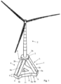
- Fig.1 shows a floating offshore structure 11 according to the invention, which has a floating foundation 1 and an offshore wind turbine 2.
- the foundation 1 comprises a transition piece 3, which is designed in the form of a plate with a side 3a facing the wind turbine and facing away from the sea surface, on which the offshore wind turbine 2 is mounted, and a lower side 3b facing away from the offshore wind turbine 2 and facing the sea surface, on which pairs of support tubes 4a, 4b, 5a, 5b, 6a, 6b are mounted.
- Figure 1 shows the foundation 1 with three pairs of support tubes 4, 5, 6, which are arranged at an angle of 60° to a horizontal. Other angular positions are of course also conceivable.
- Each of the support tubes 4a, 4b, 5a, 5b, 6a, 6b extends from the underside 3b of the transition piece 3 and one end of each tube 4a, 4b, 5a, 5b, 6a, 6b is fixedly connected to the underside 3b.
- the transition piece 3 is preferably made of concrete or steel or concrete reinforcement or a mixture of the aforementioned materials.
- the support tubes 4a, 4b, 5a, 5b, 6a, 6b are preferably made of steel.
- the pipe pairs 4, 5, 6 themselves create a redundancy, so that if a pipe 4a, 4b, 5a, 5b, 6a, 6b of a pipe pair 4, 5, 6 is damaged, for example due to a collision with a ship, the stability of the offshore wind turbine as a whole is still maintained because the other pipe 4a, 4b, 5a, 5b, 6a, 6b of the pipe pair 4, 5, 6 also takes on the load of the defective pipe 4a, 4b, 5a, 5b, 6a, 6b.
- the foundation 1 comprises a base body 8.
- the base body 8 contains at least one ballasting tank (not shown), but preferably a plurality of ballasting tanks (not shown) which are arranged inside the base body 8 and which are separated from one another by bulkheads. Each ballasting tank can be filled separately with water or with air. Pump systems are provided for this purpose, which are not shown in the drawings.
- the base body 8 is triangular in plan view, with the corners of the triangle being widened or blunted by rectangular projections 9. Of course, other shapes of the base body 8 are also conceivable, for example square, pentagonal or even higher square base body shapes. In plan view, the base body 8 has a centrally arranged passage 12 which extends over an entire height H of the base body 8.
- the support tubes 4a, 4b, 5a, 5b, 6a, 6b each have a constant diameter over their entire longitudinal extent.
- the support tubes 4a, 4b, 5a, 5b, 6a, 6b are also identical to one another.
- the foundation 1 according to the invention generates a buoyancy that is sufficient to keep the foundation 1 and the offshore wind turbine 2 mounted thereon buoyant.
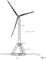
- Fig.2 shows the offshore wind turbine 2 in Fig.1 in a side view.
- the base body 8 has a constant height H over its entire horizontal extent, although other shapes of the base body 8 are of course also conceivable.
- an underside 8b of the base body 8 facing the seabed is flat so that the structure can be placed on the seabed for assembly in the harbor.
- the transition piece 3 is also plate-shaped and also has a constant height H over its entire horizontal extent.
- Fig.3 shows the foundation in a perspective view.
- the connecting pipes 7 arranged diagonally, at an angle of approximately 45°, between two support pipes 4a, 4b, 5a, 5b, 6a, 6b of a pipe pair 4, 5, 6 can be seen more clearly.
- the connecting pipes 7 are significantly smaller in diameter than the support pipes 4a, 4b, 5a, 5b, 6a, 6b.
- the diagonal connecting pipes 7 are mounted in a fixed position on the outside of the outer wall of the support pipes 4a, 4b, 5a, 5b, 6a, 6b.
- the connecting pipes 7 can also be connected to the support pipes 4a, 4b, 5a, 5b, 6a, 6b in an air or water-conducting manner.
- Fig.4 shows the foundation 1 in another side view. It is clear that the support tubes 4a, 4b, 5a, 5b, 6a, 6b are arranged along an outer circumference of the base body 8 and that five diagonal connecting tubes are provided for each pair of support legs 4, 5, 6.
- Fig.5 is the transport position and in Fig.6 the operating position of the offshore structure 11 is shown. In both positions the offshore structure 11 floats.
- ballasting tanks of the base body 8 are completely or at least largely filled with air.
- the ballasting tanks are filled with air to such an extent that the foundation 1 has a shallow draft T in order to be able to be towed out of a port in which the offshore structure 11 has been assembled.
- the offshore structure 11 is in a hydrostatically stable state in the transport position.
- the centre of buoyancy A of the offshore structure 11 is located below, i.e. facing the seabed, the centre of mass S of the offshore structure 11.
- the ballasting tanks are filled with water.
- the ballasting tanks are preferably filled with water so that the wind turbine 2 is as vertical as possible during lowering.
- other ballasting is also conceivable in which the wind turbine 2 is slightly inclined to the side at least temporarily.
- the ballasting tanks are completely filled with water or at least more filled than in the transport position.
- the center of mass S is below the center of buoyancy A and the offshore wind turbine 2 is in a weight-stable state.
- the draft T is significantly greater than in the transport position.
- anchoring ropes or chains are arranged at the corners of the base body 8, which extend from the corners of the base body 8 and lead to an anchor anchored in the seabed.
- three anchoring ropes are provided.
- two or more anchoring ropes can also be provided per corner.
- the anchors are not anchored in the seabed in a triangular manner, spaced as far apart as possible from one another in a plan view congruent with the base body, but the anchoring ropes lead to a central anchoring point in the seabed. This enables the foundation 1 to perform rotary movements and follow the wind. This means that a rotatable arrangement of the machine house on the tower of the offshore wind turbine 2 can be dispensed with.
Landscapes
- Engineering & Computer Science (AREA)
- Life Sciences & Earth Sciences (AREA)
- Sustainable Development (AREA)
- Sustainable Energy (AREA)
- Chemical & Material Sciences (AREA)
- Combustion & Propulsion (AREA)
- Mechanical Engineering (AREA)
- General Engineering & Computer Science (AREA)
- Wind Motors (AREA)
Claims (13)
- Ouvrage offshore flottant (11) avec une superstructure (2) et une fondation (1) avec un corps de base cohérent (8) avec au moins un réservoir de lestageet avec des pieds d'appui (4a, 4b, 5a, 5b, 6a, 6b) qui partent du corps de base qui mènent à une pièce de transition (3) sur laquelle est placée la superstructure (2) et l'ouvrage offshore flottant (11) flotte de manière stable en termes de poids dans une position de fonctionnement, cependant que dans la position de fonctionnement un centre de masse (M) est placé en dessous d'un centre de gravité de flottabilité (A) si bien qu'il se forme, lors de mouvements de basculement, un bras de levier redresseur qui génère une force de rappel qui replace l'ouvrage offshore flottant dans la position de fonctionnement et qu'il est configuré flottant librement,caractérisé en ce que les pieds d'appui (4, 5, 6) comprennent au moins par sections au moins deux tubes de pieds d'appui (4a, 4b, 5a, 5b, 6a, 6b) qui s'étendent parallèlement l'un à côté de l'autre.
- . Ouvrage offshore flottant selon la revendication 1,
caractérisé en ce que toutes les distances entre des tubes de pieds d'appui (4a, 4b, 5a, 5b, 6a, 6b) d'un pied d'appui (4, 5, 6) sont plus petits que toutes les distances entre des tubes de pieds d'appui (4a, 4b, 5a, 5b, 6a, 6b) de différents pieds d'appui (4, 5, 6). - . Ouvrage offshore flottant selon l'une des revendications précédentes,
caractérisé en ce qu'au moins l'un des pieds d'appui (4, 5, 6) présente par sections un corps creux à partir d'au moins un côté duquel partent au moins deux tubes de pieds d'appui (4a, 4b, 5a, 5b, 6a, 6b) qui s'étendent l'un à côté de l'autre. - . Ouvrage offshore flottant selon l'une des revendications précédentes,
caractérisé en ce que les au moins deux tubes de pieds d'appui (4a, 4b, 5a, 5b, 6a, 6b) qui s'étendent l'un à côté de l'autre sont reliés l'un à l'autre de manière rigide par des jonctions obliques (7). - . Ouvrage offshore flottant selon l'une des revendications précédentes,
caractérisé en ce que les jonctions (7) sont configurées comme des tubes de liaison. - . Ouvrage offshore flottant selon l'une des revendications précédentes,
caractérisé en ce que le corps de base (8) présente dans une vue de dessus une périphérie extérieure polygonale aux coins de laquelle les pieds d'appui (4, 5, 6) sont montés. - . Ouvrage offshore flottant selon l'une des revendications précédentes,
caractérisé en ce que le corps de base (8) est configuré en triangle dans une vue de dessus le long de la périphérie extérieure et les coins dans la vue de dessus sont élargis par des protubérances (9). - . Ouvrage offshore flottant selon l'une des revendications précédentes,
caractérisé en ce que le corps de base (8) présente dans la vue de dessus un passage central. - . Ouvrage offshore flottant selon l'une des revendications précédentes,
caractérisé en ce que la superstructure est configurée comme une éolienne ou une sous-station. - . Ouvrage offshore flottant selon l'une des revendications précédentes,
caractérisé en ce qu'une corde d'ancrage lâche part de chaque coin. - . Ouvrage offshore flottant selon l'une des revendications précédentes,
caractérisé en ce que les cordes d'ancrage partent d'un point de fixation sur le corps de base (8) qui est situé excentré par rapport à une tour de l'éolienne et permettent un autoredressement de l'ouvrage offshore flottant (11) dans le vent. - . Procédé pour l'installation d'un ouvrage offshore flottant (11) selon l'une des revendications précédentes,le au moins un réservoir de lestage étant rempli avec de l'air,l'ouvrage offshore flottant (11) étant amené hydrostatiquement stable sur le site,le au moins un réservoir de lestage étant rempli d'eau et l'ouvrage offshore flottant (11) flottant sur le site de manière stable en termes de poids dans une position de fonctionnement.
- . Procédé selon la revendication 12,
caractérisé en ce que l'ouvrage offshore flottant (11) est ancré de manière excentrée.
Applications Claiming Priority (1)
| Application Number | Priority Date | Filing Date | Title |
|---|---|---|---|
| DE102020115334.1A DE102020115334A1 (de) | 2020-06-09 | 2020-06-09 | Schwimmfähiges Offshore-Bauwerk und ein Verfahren zu seiner Installation |
Publications (2)
| Publication Number | Publication Date |
|---|---|
| EP3922845A1 EP3922845A1 (fr) | 2021-12-15 |
| EP3922845B1 true EP3922845B1 (fr) | 2024-08-21 |
Family
ID=76250151
Family Applications (1)
| Application Number | Title | Priority Date | Filing Date |
|---|---|---|---|
| EP21177294.2A Active EP3922845B1 (fr) | 2020-06-09 | 2021-06-02 | Ouvrage en mer flottant et son procédé d'installation |
Country Status (2)
| Country | Link |
|---|---|
| EP (1) | EP3922845B1 (fr) |
| DE (1) | DE102020115334A1 (fr) |
Families Citing this family (1)
| Publication number | Priority date | Publication date | Assignee | Title |
|---|---|---|---|---|
| GB202203823D0 (en) * | 2022-03-18 | 2022-05-04 | Marine Power Systems Ltd | Renewable energy platform assembly kit and method |
Citations (1)
| Publication number | Priority date | Publication date | Assignee | Title |
|---|---|---|---|---|
| US3540396A (en) * | 1968-06-07 | 1970-11-17 | Deep Oil Technology Inc | Offshore well apparatus and system |
Family Cites Families (17)
| Publication number | Priority date | Publication date | Assignee | Title |
|---|---|---|---|---|
| US3577946A (en) | 1969-02-06 | 1971-05-11 | Deep Oil Technology Inc | Stable marine construction |
| NO166400C (no) | 1986-03-11 | 1991-07-17 | Fred Olsen | Anodning ved delvis nedsenkbar plattform. |
| ES1020135Y (es) | 1992-02-13 | 1993-01-01 | Martinez Mendiguchia Miguel Angel | Nueva barbacoa multiuso. |
| AU2001242321A1 (en) | 2000-03-28 | 2001-10-08 | Per Lauritsen | Floating offshore wind power installation |
| AU2003213772A1 (en) | 2002-03-08 | 2003-09-22 | Ocean Wind Energy Systems | Offshore wind turbine |
| US7086809B2 (en) | 2003-01-21 | 2006-08-08 | Marine Innovation & Technology | Minimum floating offshore platform with water entrapment plate and method of installation |
| JP2010280301A (ja) | 2009-06-04 | 2010-12-16 | Shimizu Corp | 洋上施設用浮体構造物および洋上施設の施工方法 |
| FR2955828B1 (fr) | 2010-01-29 | 2012-04-20 | Dcns | Support flottant pour structure off-shore telle que notamment une eolienne |
| US9394035B2 (en) * | 2010-11-04 | 2016-07-19 | University Of Maine System Board Of Trustees | Floating wind turbine platform and method of assembling |
| FR2970695B1 (fr) | 2011-01-25 | 2013-01-04 | Dcns | Support flottant pour structure offshore de type eolienne |
| FR2970694B1 (fr) | 2011-01-25 | 2015-07-03 | Dcns | Support flottant pour structure de type eolienne |
| NO334535B1 (no) | 2012-08-23 | 2014-03-31 | Olav Olsen As Dr Techn | Flytende, halvt nedsenkbart skrog for opplagring av fortrinnsvis én eller flere vindturbiner |
| PL2992208T3 (pl) | 2013-05-20 | 2019-01-31 | Principle Power Inc | System i sposób sterowania morskimi pływającymi platformami turbin wiatrowych |
| DE102013111115B3 (de) | 2013-10-08 | 2015-01-22 | Linnhoff Offshore AG | Schwimmfähige Offshore-Windkraftanlage |
| FR3051022B1 (fr) | 2016-05-03 | 2022-08-12 | Dcns | Flotteur d'eolienne offshore |
| KR20180108195A (ko) | 2017-03-24 | 2018-10-04 | 마스텍중공업 주식회사 | 부유식 해상 풍력발전설비 |
| US10716296B2 (en) * | 2017-11-15 | 2020-07-21 | Graduate School At Shenzhen, Tsinghua University | Floating offshore wind turbine integrated with steel fish farming cage |
-
2020
- 2020-06-09 DE DE102020115334.1A patent/DE102020115334A1/de not_active Withdrawn
-
2021
- 2021-06-02 EP EP21177294.2A patent/EP3922845B1/fr active Active
Patent Citations (1)
| Publication number | Priority date | Publication date | Assignee | Title |
|---|---|---|---|---|
| US3540396A (en) * | 1968-06-07 | 1970-11-17 | Deep Oil Technology Inc | Offshore well apparatus and system |
Also Published As
| Publication number | Publication date |
|---|---|
| DE102020115334A1 (de) | 2021-12-09 |
| EP3922845A1 (fr) | 2021-12-15 |
Similar Documents
| Publication | Publication Date | Title |
|---|---|---|
| EP1288122B1 (fr) | Support flottant pour une construction s'élevant au dessus de la surface de l'eau | |
| EP2360373B1 (fr) | Installation offshore, fondation d'une installation offshore et procédé d'établissement d'une installation offshore | |
| DE10349109B4 (de) | Gründung für eine Offshore-Windenergieanlage | |
| DE102008003647B4 (de) | Schwimmendes Gründungstragwerk mit Auftriebskomponenten, in aufgelöster Bauweise | |
| EP3019740B1 (fr) | Éolienne flottante à base flottante et procédé d'installation d'une éolienne flottante de ce type | |
| DE60126984T2 (de) | Verfahren und vorrichtung zur anordnung mindestens einer windturbine an offenem wasser | |
| EP2522780B1 (fr) | Fondation offshore pour éolienne | |
| DE2345274A1 (de) | Hebbare hochseeplattform | |
| DE102010020995B4 (de) | Gründungssystem für die Gründung einer Offshore-Windenergieanlage | |
| EP1876093A1 (fr) | Fondation offshore flottante et procédé de son réalisation | |
| DE2424698A1 (de) | Offshore-konstruktion in form eines turms | |
| EP3428345A1 (fr) | Fondation pour une éolienne en mer | |
| CH715604B1 (de) | Stützstruktursystem für eine Offshore-Windkraftanlage. | |
| WO2018054532A1 (fr) | Ouvrage destiné à être érigé à la surface d'étendues d'eau et procédé pour son érection | |
| DE10357392B4 (de) | Transportsystem für ein Turmbauwerk | |
| WO2016177783A1 (fr) | Ancre-poids flottante permettant d'ancrer une structure porteuse flottant en pleine mer à une éolienne, une station-service ou une station de conversion | |
| EP2623674A1 (fr) | Infrastructure pour une plateforme offshore et procédé d'installation d'une telle infrastructure | |
| DE102011109251A1 (de) | Katamaran-Ponton | |
| EP3922845A1 (fr) | Ouvrage en mer flottant et son procédé d'installation | |
| DE202010010094U1 (de) | Gründungssystem für die Gründung einer Offshore-Windenergieanlage | |
| EP2623675A1 (fr) | Partie supérieure d'une plateforme offshore et procédé d'installation d'une telle partie supérieure d'une plateforme | |
| DE102008031042A1 (de) | Modulare Schwimmeinheit für Wind- und Strömungsenergieanlagen auf See | |
| DE102021119100A1 (de) | Anordnung zur Gründung eines Hochbauwerks in einem wasserbedeckten Grund, insbesondere zur Monopile-Gründung einer Offshore-Windenergieanlage, und Montageverfahren hierfür | |
| DE3520181A1 (de) | Schwimmende plattform fuer universelle verwendung | |
| DE102011120378A1 (de) | Offshore-Windkraftanlage und Verfahren zum Aufbau und zur Aufstellung der Offshore-Windkraftanlage |
Legal Events
| Date | Code | Title | Description |
|---|---|---|---|
| PUAI | Public reference made under article 153(3) epc to a published international application that has entered the european phase |
Free format text: ORIGINAL CODE: 0009012 |
|
| STAA | Information on the status of an ep patent application or granted ep patent |
Free format text: STATUS: THE APPLICATION HAS BEEN PUBLISHED |
|
| AK | Designated contracting states |
Kind code of ref document: A1 Designated state(s): AL AT BE BG CH CY CZ DE DK EE ES FI FR GB GR HR HU IE IS IT LI LT LU LV MC MK MT NL NO PL PT RO RS SE SI SK SM TR |
|
| B565 | Issuance of search results under rule 164(2) epc |
Effective date: 20211103 |
|
| STAA | Information on the status of an ep patent application or granted ep patent |
Free format text: STATUS: REQUEST FOR EXAMINATION WAS MADE |
|
| 17P | Request for examination filed |
Effective date: 20220614 |
|
| RBV | Designated contracting states (corrected) |
Designated state(s): AL AT BE BG CH CY CZ DE DK EE ES FI FR GB GR HR HU IE IS IT LI LT LU LV MC MK MT NL NO PL PT RO RS SE SI SK SM TR |
|
| STAA | Information on the status of an ep patent application or granted ep patent |
Free format text: STATUS: EXAMINATION IS IN PROGRESS |
|
| 17Q | First examination report despatched |
Effective date: 20230417 |
|
| GRAP | Despatch of communication of intention to grant a patent |
Free format text: ORIGINAL CODE: EPIDOSNIGR1 |
|
| STAA | Information on the status of an ep patent application or granted ep patent |
Free format text: STATUS: GRANT OF PATENT IS INTENDED |
|
| INTG | Intention to grant announced |
Effective date: 20240425 |
|
| GRAS | Grant fee paid |
Free format text: ORIGINAL CODE: EPIDOSNIGR3 |
|
| GRAA | (expected) grant |
Free format text: ORIGINAL CODE: 0009210 |
|
| STAA | Information on the status of an ep patent application or granted ep patent |
Free format text: STATUS: THE PATENT HAS BEEN GRANTED |
|
| AK | Designated contracting states |
Kind code of ref document: B1 Designated state(s): AL AT BE BG CH CY CZ DE DK EE ES FI FR GB GR HR HU IE IS IT LI LT LU LV MC MK MT NL NO PL PT RO RS SE SI SK SM TR |
|
| REG | Reference to a national code |
Ref country code: GB Ref legal event code: FG4D Free format text: NOT ENGLISH |
|
| REG | Reference to a national code |
Ref country code: CH Ref legal event code: EP |
|
| REG | Reference to a national code |
Ref country code: DE Ref legal event code: R096 Ref document number: 502021004831 Country of ref document: DE |
|
| REG | Reference to a national code |
Ref country code: IE Ref legal event code: FG4D Free format text: LANGUAGE OF EP DOCUMENT: GERMAN |
|
| REG | Reference to a national code |
Ref country code: LT Ref legal event code: MG9D |
|
| REG | Reference to a national code |
Ref country code: NL Ref legal event code: MP Effective date: 20240821 |
|
| PG25 | Lapsed in a contracting state [announced via postgrant information from national office to epo] |
Ref country code: NO Free format text: LAPSE BECAUSE OF FAILURE TO SUBMIT A TRANSLATION OF THE DESCRIPTION OR TO PAY THE FEE WITHIN THE PRESCRIBED TIME-LIMIT Effective date: 20241121 |
|
| PG25 | Lapsed in a contracting state [announced via postgrant information from national office to epo] |
Ref country code: NL Free format text: LAPSE BECAUSE OF FAILURE TO SUBMIT A TRANSLATION OF THE DESCRIPTION OR TO PAY THE FEE WITHIN THE PRESCRIBED TIME-LIMIT Effective date: 20240821 Ref country code: FI Free format text: LAPSE BECAUSE OF FAILURE TO SUBMIT A TRANSLATION OF THE DESCRIPTION OR TO PAY THE FEE WITHIN THE PRESCRIBED TIME-LIMIT Effective date: 20240821 Ref country code: PT Free format text: LAPSE BECAUSE OF FAILURE TO SUBMIT A TRANSLATION OF THE DESCRIPTION OR TO PAY THE FEE WITHIN THE PRESCRIBED TIME-LIMIT Effective date: 20241223 Ref country code: PL Free format text: LAPSE BECAUSE OF FAILURE TO SUBMIT A TRANSLATION OF THE DESCRIPTION OR TO PAY THE FEE WITHIN THE PRESCRIBED TIME-LIMIT Effective date: 20240821 Ref country code: GR Free format text: LAPSE BECAUSE OF FAILURE TO SUBMIT A TRANSLATION OF THE DESCRIPTION OR TO PAY THE FEE WITHIN THE PRESCRIBED TIME-LIMIT Effective date: 20241122 |
|
| PG25 | Lapsed in a contracting state [announced via postgrant information from national office to epo] |
Ref country code: BG Free format text: LAPSE BECAUSE OF FAILURE TO SUBMIT A TRANSLATION OF THE DESCRIPTION OR TO PAY THE FEE WITHIN THE PRESCRIBED TIME-LIMIT Effective date: 20240821 |
|
| PG25 | Lapsed in a contracting state [announced via postgrant information from national office to epo] |
Ref country code: LV Free format text: LAPSE BECAUSE OF FAILURE TO SUBMIT A TRANSLATION OF THE DESCRIPTION OR TO PAY THE FEE WITHIN THE PRESCRIBED TIME-LIMIT Effective date: 20240821 |
|
| PG25 | Lapsed in a contracting state [announced via postgrant information from national office to epo] |
Ref country code: IS Free format text: LAPSE BECAUSE OF FAILURE TO SUBMIT A TRANSLATION OF THE DESCRIPTION OR TO PAY THE FEE WITHIN THE PRESCRIBED TIME-LIMIT Effective date: 20241221 |
|
| PG25 | Lapsed in a contracting state [announced via postgrant information from national office to epo] |
Ref country code: HR Free format text: LAPSE BECAUSE OF FAILURE TO SUBMIT A TRANSLATION OF THE DESCRIPTION OR TO PAY THE FEE WITHIN THE PRESCRIBED TIME-LIMIT Effective date: 20240821 |
|
| PG25 | Lapsed in a contracting state [announced via postgrant information from national office to epo] |
Ref country code: ES Free format text: LAPSE BECAUSE OF FAILURE TO SUBMIT A TRANSLATION OF THE DESCRIPTION OR TO PAY THE FEE WITHIN THE PRESCRIBED TIME-LIMIT Effective date: 20240821 Ref country code: RS Free format text: LAPSE BECAUSE OF FAILURE TO SUBMIT A TRANSLATION OF THE DESCRIPTION OR TO PAY THE FEE WITHIN THE PRESCRIBED TIME-LIMIT Effective date: 20241121 |
|
| PG25 | Lapsed in a contracting state [announced via postgrant information from national office to epo] |
Ref country code: RS Free format text: LAPSE BECAUSE OF FAILURE TO SUBMIT A TRANSLATION OF THE DESCRIPTION OR TO PAY THE FEE WITHIN THE PRESCRIBED TIME-LIMIT Effective date: 20241121 Ref country code: PT Free format text: LAPSE BECAUSE OF FAILURE TO SUBMIT A TRANSLATION OF THE DESCRIPTION OR TO PAY THE FEE WITHIN THE PRESCRIBED TIME-LIMIT Effective date: 20241223 Ref country code: PL Free format text: LAPSE BECAUSE OF FAILURE TO SUBMIT A TRANSLATION OF THE DESCRIPTION OR TO PAY THE FEE WITHIN THE PRESCRIBED TIME-LIMIT Effective date: 20240821 Ref country code: NO Free format text: LAPSE BECAUSE OF FAILURE TO SUBMIT A TRANSLATION OF THE DESCRIPTION OR TO PAY THE FEE WITHIN THE PRESCRIBED TIME-LIMIT Effective date: 20241121 Ref country code: NL Free format text: LAPSE BECAUSE OF FAILURE TO SUBMIT A TRANSLATION OF THE DESCRIPTION OR TO PAY THE FEE WITHIN THE PRESCRIBED TIME-LIMIT Effective date: 20240821 Ref country code: LV Free format text: LAPSE BECAUSE OF FAILURE TO SUBMIT A TRANSLATION OF THE DESCRIPTION OR TO PAY THE FEE WITHIN THE PRESCRIBED TIME-LIMIT Effective date: 20240821 Ref country code: IS Free format text: LAPSE BECAUSE OF FAILURE TO SUBMIT A TRANSLATION OF THE DESCRIPTION OR TO PAY THE FEE WITHIN THE PRESCRIBED TIME-LIMIT Effective date: 20241221 Ref country code: HR Free format text: LAPSE BECAUSE OF FAILURE TO SUBMIT A TRANSLATION OF THE DESCRIPTION OR TO PAY THE FEE WITHIN THE PRESCRIBED TIME-LIMIT Effective date: 20240821 Ref country code: GR Free format text: LAPSE BECAUSE OF FAILURE TO SUBMIT A TRANSLATION OF THE DESCRIPTION OR TO PAY THE FEE WITHIN THE PRESCRIBED TIME-LIMIT Effective date: 20241122 Ref country code: FI Free format text: LAPSE BECAUSE OF FAILURE TO SUBMIT A TRANSLATION OF THE DESCRIPTION OR TO PAY THE FEE WITHIN THE PRESCRIBED TIME-LIMIT Effective date: 20240821 Ref country code: ES Free format text: LAPSE BECAUSE OF FAILURE TO SUBMIT A TRANSLATION OF THE DESCRIPTION OR TO PAY THE FEE WITHIN THE PRESCRIBED TIME-LIMIT Effective date: 20240821 Ref country code: BG Free format text: LAPSE BECAUSE OF FAILURE TO SUBMIT A TRANSLATION OF THE DESCRIPTION OR TO PAY THE FEE WITHIN THE PRESCRIBED TIME-LIMIT Effective date: 20240821 |
|
| PG25 | Lapsed in a contracting state [announced via postgrant information from national office to epo] |
Ref country code: SM Free format text: LAPSE BECAUSE OF FAILURE TO SUBMIT A TRANSLATION OF THE DESCRIPTION OR TO PAY THE FEE WITHIN THE PRESCRIBED TIME-LIMIT Effective date: 20240821 Ref country code: DK Free format text: LAPSE BECAUSE OF FAILURE TO SUBMIT A TRANSLATION OF THE DESCRIPTION OR TO PAY THE FEE WITHIN THE PRESCRIBED TIME-LIMIT Effective date: 20240821 Ref country code: RO Free format text: LAPSE BECAUSE OF FAILURE TO SUBMIT A TRANSLATION OF THE DESCRIPTION OR TO PAY THE FEE WITHIN THE PRESCRIBED TIME-LIMIT Effective date: 20240821 |
|
| PG25 | Lapsed in a contracting state [announced via postgrant information from national office to epo] |
Ref country code: EE Free format text: LAPSE BECAUSE OF FAILURE TO SUBMIT A TRANSLATION OF THE DESCRIPTION OR TO PAY THE FEE WITHIN THE PRESCRIBED TIME-LIMIT Effective date: 20240821 |
|
| PG25 | Lapsed in a contracting state [announced via postgrant information from national office to epo] |
Ref country code: CZ Free format text: LAPSE BECAUSE OF FAILURE TO SUBMIT A TRANSLATION OF THE DESCRIPTION OR TO PAY THE FEE WITHIN THE PRESCRIBED TIME-LIMIT Effective date: 20240821 |
|
| PG25 | Lapsed in a contracting state [announced via postgrant information from national office to epo] |
Ref country code: IT Free format text: LAPSE BECAUSE OF FAILURE TO SUBMIT A TRANSLATION OF THE DESCRIPTION OR TO PAY THE FEE WITHIN THE PRESCRIBED TIME-LIMIT Effective date: 20240821 Ref country code: SK Free format text: LAPSE BECAUSE OF FAILURE TO SUBMIT A TRANSLATION OF THE DESCRIPTION OR TO PAY THE FEE WITHIN THE PRESCRIBED TIME-LIMIT Effective date: 20240821 |
|
| REG | Reference to a national code |
Ref country code: DE Ref legal event code: R097 Ref document number: 502021004831 Country of ref document: DE |
|
| PLBE | No opposition filed within time limit |
Free format text: ORIGINAL CODE: 0009261 |
|
| STAA | Information on the status of an ep patent application or granted ep patent |
Free format text: STATUS: NO OPPOSITION FILED WITHIN TIME LIMIT |
|
| PGFP | Annual fee paid to national office [announced via postgrant information from national office to epo] |
Ref country code: AT Payment date: 20250721 Year of fee payment: 5 |
|
| 26N | No opposition filed |
Effective date: 20250522 |
|
| PG25 | Lapsed in a contracting state [announced via postgrant information from national office to epo] |
Ref country code: SE Free format text: LAPSE BECAUSE OF FAILURE TO SUBMIT A TRANSLATION OF THE DESCRIPTION OR TO PAY THE FEE WITHIN THE PRESCRIBED TIME-LIMIT Effective date: 20240821 |
|
| REG | Reference to a national code |
Ref country code: DE Ref legal event code: R119 Ref document number: 502021004831 Country of ref document: DE |
|
| REG | Reference to a national code |
Ref country code: CH Ref legal event code: H13 Free format text: ST27 STATUS EVENT CODE: U-0-0-H10-H13 (AS PROVIDED BY THE NATIONAL OFFICE) Effective date: 20260127 |
|
| PG25 | Lapsed in a contracting state [announced via postgrant information from national office to epo] |
Ref country code: MC Free format text: LAPSE BECAUSE OF FAILURE TO SUBMIT A TRANSLATION OF THE DESCRIPTION OR TO PAY THE FEE WITHIN THE PRESCRIBED TIME-LIMIT Effective date: 20240821 |
|
| PG25 | Lapsed in a contracting state [announced via postgrant information from national office to epo] |
Ref country code: LU Free format text: LAPSE BECAUSE OF NON-PAYMENT OF DUE FEES Effective date: 20250602 |
|
| GBPC | Gb: european patent ceased through non-payment of renewal fee |
Effective date: 20250602 |
|
| REG | Reference to a national code |
Ref country code: BE Ref legal event code: MM Effective date: 20250630 |
|
| PG25 | Lapsed in a contracting state [announced via postgrant information from national office to epo] |
Ref country code: GB Free format text: LAPSE BECAUSE OF NON-PAYMENT OF DUE FEES Effective date: 20250602 |
|
| PG25 | Lapsed in a contracting state [announced via postgrant information from national office to epo] |
Ref country code: IE Free format text: LAPSE BECAUSE OF NON-PAYMENT OF DUE FEES Effective date: 20250602 Ref country code: DE Free format text: LAPSE BECAUSE OF NON-PAYMENT OF DUE FEES Effective date: 20260101 |
|
| PG25 | Lapsed in a contracting state [announced via postgrant information from national office to epo] |
Ref country code: BE Free format text: LAPSE BECAUSE OF NON-PAYMENT OF DUE FEES Effective date: 20250630 |
|
| PG25 | Lapsed in a contracting state [announced via postgrant information from national office to epo] |
Ref country code: FR Free format text: LAPSE BECAUSE OF NON-PAYMENT OF DUE FEES Effective date: 20250630 |
|
| PG25 | Lapsed in a contracting state [announced via postgrant information from national office to epo] |
Ref country code: CH Free format text: LAPSE BECAUSE OF NON-PAYMENT OF DUE FEES Effective date: 20250630 |