EP3922855A1 - Roue pour une pompe centrifuge - Google Patents
Roue pour une pompe centrifuge Download PDFInfo
- Publication number
- EP3922855A1 EP3922855A1 EP21178554.8A EP21178554A EP3922855A1 EP 3922855 A1 EP3922855 A1 EP 3922855A1 EP 21178554 A EP21178554 A EP 21178554A EP 3922855 A1 EP3922855 A1 EP 3922855A1
- Authority
- EP
- European Patent Office
- Prior art keywords
- impeller
- degrees
- leading edge
- hub
- centrifugal pump
- Prior art date
- Legal status (The legal status is an assumption and is not a legal conclusion. Google has not performed a legal analysis and makes no representation as to the accuracy of the status listed.)
- Withdrawn
Links
- 239000007788 liquid Substances 0.000 claims abstract description 7
- 239000007787 solid Substances 0.000 claims abstract description 7
- 239000000463 material Substances 0.000 description 6
- 239000010802 sludge Substances 0.000 description 3
- 229910001018 Cast iron Inorganic materials 0.000 description 1
- 229910001208 Crucible steel Inorganic materials 0.000 description 1
- 208000012886 Vertigo Diseases 0.000 description 1
- 238000004140 cleaning Methods 0.000 description 1
- 230000000694 effects Effects 0.000 description 1
- 239000000835 fiber Substances 0.000 description 1
- 239000010842 industrial wastewater Substances 0.000 description 1
- 239000000203 mixture Substances 0.000 description 1
- 238000012986 modification Methods 0.000 description 1
- 230000004048 modification Effects 0.000 description 1
- 239000010841 municipal wastewater Substances 0.000 description 1
- 230000002093 peripheral effect Effects 0.000 description 1
- 238000005086 pumping Methods 0.000 description 1
- 238000007528 sand casting Methods 0.000 description 1
- 239000011343 solid material Substances 0.000 description 1
- 230000007704 transition Effects 0.000 description 1
Images




Classifications
-
- F—MECHANICAL ENGINEERING; LIGHTING; HEATING; WEAPONS; BLASTING
- F04—POSITIVE - DISPLACEMENT MACHINES FOR LIQUIDS; PUMPS FOR LIQUIDS OR ELASTIC FLUIDS
- F04D—NON-POSITIVE-DISPLACEMENT PUMPS
- F04D29/00—Details, component parts, or accessories
- F04D29/18—Rotors
- F04D29/22—Rotors specially for centrifugal pumps
- F04D29/24—Vanes
- F04D29/242—Geometry, shape
-
- F—MECHANICAL ENGINEERING; LIGHTING; HEATING; WEAPONS; BLASTING
- F04—POSITIVE - DISPLACEMENT MACHINES FOR LIQUIDS; PUMPS FOR LIQUIDS OR ELASTIC FLUIDS
- F04D—NON-POSITIVE-DISPLACEMENT PUMPS
- F04D29/00—Details, component parts, or accessories
- F04D29/18—Rotors
- F04D29/22—Rotors specially for centrifugal pumps
- F04D29/2261—Rotors specially for centrifugal pumps with special measures
-
- F—MECHANICAL ENGINEERING; LIGHTING; HEATING; WEAPONS; BLASTING
- F04—POSITIVE - DISPLACEMENT MACHINES FOR LIQUIDS; PUMPS FOR LIQUIDS OR ELASTIC FLUIDS
- F04D—NON-POSITIVE-DISPLACEMENT PUMPS
- F04D29/00—Details, component parts, or accessories
- F04D29/18—Rotors
- F04D29/22—Rotors specially for centrifugal pumps
- F04D29/2261—Rotors specially for centrifugal pumps with special measures
- F04D29/2288—Rotors specially for centrifugal pumps with special measures for comminuting, mixing or separating
-
- F—MECHANICAL ENGINEERING; LIGHTING; HEATING; WEAPONS; BLASTING
- F04—POSITIVE - DISPLACEMENT MACHINES FOR LIQUIDS; PUMPS FOR LIQUIDS OR ELASTIC FLUIDS
- F04D—NON-POSITIVE-DISPLACEMENT PUMPS
- F04D29/00—Details, component parts, or accessories
- F04D29/18—Rotors
- F04D29/22—Rotors specially for centrifugal pumps
- F04D29/24—Vanes
- F04D29/242—Geometry, shape
- F04D29/245—Geometry, shape for special effects
-
- F—MECHANICAL ENGINEERING; LIGHTING; HEATING; WEAPONS; BLASTING
- F04—POSITIVE - DISPLACEMENT MACHINES FOR LIQUIDS; PUMPS FOR LIQUIDS OR ELASTIC FLUIDS
- F04D—NON-POSITIVE-DISPLACEMENT PUMPS
- F04D7/00—Pumps adapted for handling specific fluids, e.g. by selection of specific materials for pumps or pump parts
- F04D7/02—Pumps adapted for handling specific fluids, e.g. by selection of specific materials for pumps or pump parts of centrifugal type
- F04D7/04—Pumps adapted for handling specific fluids, e.g. by selection of specific materials for pumps or pump parts of centrifugal type the fluids being viscous or non-homogenous
-
- F—MECHANICAL ENGINEERING; LIGHTING; HEATING; WEAPONS; BLASTING
- F04—POSITIVE - DISPLACEMENT MACHINES FOR LIQUIDS; PUMPS FOR LIQUIDS OR ELASTIC FLUIDS
- F04D—NON-POSITIVE-DISPLACEMENT PUMPS
- F04D7/00—Pumps adapted for handling specific fluids, e.g. by selection of specific materials for pumps or pump parts
- F04D7/02—Pumps adapted for handling specific fluids, e.g. by selection of specific materials for pumps or pump parts of centrifugal type
- F04D7/04—Pumps adapted for handling specific fluids, e.g. by selection of specific materials for pumps or pump parts of centrifugal type the fluids being viscous or non-homogenous
- F04D7/045—Pumps adapted for handling specific fluids, e.g. by selection of specific materials for pumps or pump parts of centrifugal type the fluids being viscous or non-homogenous with means for comminuting, mixing stirring or otherwise treating
-
- F—MECHANICAL ENGINEERING; LIGHTING; HEATING; WEAPONS; BLASTING
- F05—INDEXING SCHEMES RELATING TO ENGINES OR PUMPS IN VARIOUS SUBCLASSES OF CLASSES F01-F04
- F05D—INDEXING SCHEME FOR ASPECTS RELATING TO NON-POSITIVE-DISPLACEMENT MACHINES OR ENGINES, GAS-TURBINES OR JET-PROPULSION PLANTS
- F05D2240/00—Components
- F05D2240/20—Rotors
- F05D2240/30—Characteristics of rotor blades, i.e. of any element transforming dynamic fluid energy to or from rotational energy and being attached to a rotor
- F05D2240/303—Characteristics of rotor blades, i.e. of any element transforming dynamic fluid energy to or from rotational energy and being attached to a rotor related to the leading edge of a rotor blade
Definitions
- the present invention relates to an impeller for a centrifugal pump.
- Impellers of this type are used in centrifugal pumps in order to be able to convey liquids containing solids in particular.
- the aim is to provide the largest possible cross-sections between the blade surfaces so that large solid bodies can also pass through.
- the flow conditions can also be such that the solid material, e.g. if it is in a flexible, flat form, does not get over the leading edge of a blade, but rather sticks to the leading edge and is only whirled around by the impeller. Such material accumulates in front of the impeller until the pump is finally completely clogged.
- the impeller comprises blades, the leading edges of which rise from a hub contact point to an apex, are curved against the direction of rotation of the impeller when viewed from above and have an angle of inclination of less than 15 degrees.
- the shape of the blade facilitates the entry of particularly flexible, flat material into the impeller, so that the risk of clogging is reduced.
- the impeller can be designed in such a way that the blades have pronounced surfaces so that a correspondingly good pumping effect can be achieved.
- the impeller there is preferably an axis A for the respective leading edge which passes through the hub contact point and the axis of rotation of the impeller and which is perpendicular to this axis of rotation, the leading edge going away transversely to axis A, so that the tangent (T ) at the leading edge has an angle ( ⁇ ) to the axis A, which is in the range of 45 degrees to 90 Degrees, preferably in the range 60 degrees to 90 degrees, particularly preferably in the range 70 degrees to 90 degrees.
- a centrifugal pump is preferably provided with an impeller and with a wall which has grooves on the inside. When viewed from above, these can be straight or curved. The grooves also facilitate the passage of flexible, flat material, so that this is carried away and the centrifugal pump is thereby self-cleaning. It is not necessary to provide a cutting device which shreds the material.
- Fig. 1 shows an impeller 10 for a centrifugal pump, for example as shown in FIG Fig. 9 is shown.
- the impeller 10 has a hub body 11 around which a plate 15 with two blades 20, 20 'is arranged.
- the hub body 11 is provided with a central bore 12 into which the drivable shaft 60 can be inserted at the rear and the end of a fastening screw 61 can be inserted at the front (cf. Fig. 9 ).
- the central bore 12 has a longitudinal groove 13 in which a bar on the shaft 60 can grip for the rotationally fixed connection.
- the plate 15 has a plate surface 16 on the front side which slopes continuously towards the periphery of the plate 15, preferably in a convex curvature.
- the two blades 20, 20 ′ are configured identically here and are arranged circumferentially offset by 180 degrees on the plate surface 16.
- the first blade 20 is explained in more detail below. The explanation applies in an analogous manner to the second blade 20 '.
- the blade 20 extends from the hub body 11 with a radially outward curvature and has a suction-side blade surface 21 and a pressure-side blade surface 22. As well as Fig. 2 shows, the blade surfaces 21, 22 are arranged inclined to the axis of rotation R of the impeller 10.
- leading edge 24 On the inlet side of the impeller 10, the transition from the blade surface 21 to the blade surface 22 is given by a leading edge 24. This extends from a hub contact point 23 on the hub body 11 to an apex 25. The leading edge 24 adjoins the end face 26 of the blade 20, which extends from the apex 25 to the trailing edge 27.
- the leading edge 24 here has a round profile (cf. in this regard in Fig. 2 the profile of the leading edge 24 'of the second blade 20' at the apex 25 ').
- the wall thickness of the blade 20 is reduced in the peripheral region of the plate 15 in that the blade surface 22 is beveled towards the blade surface 21.
- the trailing edge 27 is curved forward, ie in the direction of rotation D of the impeller 10 (cf. Fig. 2 ).
- the second blade 20 ' has the same structure as the first blade 20 and has the analogous elements 21'-27', which correspond to the elements 21-27 of the first blade 20.
- a level plane N is indicated, which is perpendicular to the axis of rotation R and is at the level of the hub contact point 23 or 23 '.
- the level plane N runs in the vicinity of the end face of the hub body 11, so that it only extends slightly above the level plane N.
- the leading edge 24, 24 ' rises from the hub contact point 23, 23' to the apex 25, 25 ', from where the end face 26, 26' drops, here below the level level N.
- the leading edge 24, 24 ' is strongly from inclined away from the axis of rotation R, so that the vertex 25, 25 'is closer to the level plane N than to the axis of rotation R.
- the angle of inclination ⁇ of the leading edge 23 with respect to the level plane N can be defined, for example, as follows, cf. Fig. 3-5 :
- A defines the axis which passes through the hub contact points 23 and 23 'and P the plane of projection which is perpendicular to the axis A and passes through the hub contact point 23.
- Rp defines the axis which lies in the projection plane P and runs parallel to the axis of rotation R of the impeller 10.
- the point 25p is the vertex 25 projected onto the projection plane P, in that it is rotated about the axis Rp until it comes to lie on the projection plane P.
- the points 25 and 25p thus have the same radial distance from the axis Rp.
- Lp defines the straight line that goes through the hub contact point 23 and the vertex 25p projected onto P. (Lp thus runs in the projection plane P.)
- the angle of inclination ⁇ is the angle between the level plane N and the straight line Lp and is selected to be greater than 0 degrees and less than 15 degrees. Preferably the angle is in the range of 5 to 10 degrees.
- the angle ⁇ can alternatively also be defined as the angle between the level plane N and the straight line L which goes through the hub contact point 23 and the vertex 25.
- the leading edge 24 ' is inclined with respect to the level plane N at an angle ⁇ , which is the angle between the level plane N and the straight line that goes through the hub contact point 23' and the vertex 25 '.
- the leading edge 24 lies on a surface of revolution which results when the straight line L is rotated about the axis Rp.
- the leading edge 24 thus lies on a cone with the tip at the hub contact point 23.
- the leading edge 24 ' lies on a cone with the tip at the hub contact point 23'.
- the plate 15 has a circular edge 17.
- the plate surface 16 is free of cutouts so that it extends all the way to the edge 17.
- the end face 11a of the hub body 11 has a circular edge with a diameter D1. This corresponds to the distance D1 between the two hub contact points 23 and 23 '.
- D1 is selected here to be relatively small in relation to the diameter D2 of the plate 15. Typically D1 is at most 30% of D2, preferably at most 25%, and / or at least 15% of D2; e.g. D1 is in the range of 20% -25% of D2.
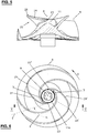
- the leading edge 24, 24 ' is curved backwards when viewed in the radial direction, ie opposite to the direction of rotation D. Seen in the top view, the vertex 25, 25 'is thus arranged offset in relation to the hub contact point 23, 23' by an angle ⁇ in the circumferential direction of the axis of rotation R, cf. Fig. 6 .
- the angle y also called looping, is typically at least 90 degrees, preferably at least 100 degrees and / or at least 110 degrees.
- the angle of wrap of the entire blade 20, 20 ', ie from the hub contact point 23, 23' to the foremost end of the trailing edge 27, 27 ', when viewed from above, is at least 180 degrees, at least 200 degrees, at least 225 degrees, at least 250 degrees with increasing preference , at least 270 degrees.
- the leading edge 24, 24 'does not go perpendicularly away from the hub body 11, but hugs it as tangentially as possible.
- T defines the tangent of the leading edge 24 to the hub contact point 23.
- the axis A corresponds to the normal to the end face 11a of the hub body 11 in the plan view.
- the angle ⁇ between A and T is preferably selected to be greater than 60 degrees, particularly preferably greater than 70 degrees.
- leading edge 24 ' has an angle ⁇ , which is the angle between the tangent of the leading edge 24' to the hub contact point 23 'and the axis A.
- the impeller 10 shown here has back blades 40 on the rear of the plate 15, cf. Fig. 7 .
- a respective back vane 40 extends from the entry point 41 with a radial curvature to the exit point 42.
- the entry point 41 is arranged at a distance from the hub body 11.
- the exit point 42 is located here on the edge 17 of the plate 15.
- four back blades 40 are provided, each of which is evenly distributed in the circumferential direction of the axis of rotation R on the back of the plate 15.
- the number can also be chosen differently and can be, for example, one, two, three or more.
- Fig. 8 a further illustration of the impeller 10 together with part of an annular wear wall 50 is shown.
- the hub body 11 and the plate 15 of the impeller 10 are shown here in section, while the contour of the blades 20, 20 ', 40 is drawn, which is the free edge of a blade 20, 20', 40 seen in the side view during a rotation draws 360 degrees.
- the leading edges 24, 24 ', the end faces 26, 26' and the trailing edges 27, 27 'generate a profile which is defined by the lines 24r, 26r, 27r in FIG Fig. 8 is shown.
- 23r and 25r denote the point where the hub contact point 23, 23 'and the vertex 25, 25' come to lie.
- the leading edge 24, 24 ' is shaped here in such a way that the line 24r is straight.
- the wear wall 50 is arranged in a stationary manner.
- a gap which is preferably less than 2 mm, is provided between the contour line 26r and the wear wall 50.
- the impeller 10 can be produced in one piece, e.g. as a cast part, e.g. from cast iron or cast steel.
- the blades 20, 20 ' have undercuts.
- the arrangement and shape of the blades 20, 20 ′ are selected such that a sand casting mold can be created which enables the model to be removed from the mold.
- Fig. 9 shows the impeller 10 arranged in the pump housing 70, which is fastened to the shaft 60 by means of a screw 61.
- the head of the screw 61 is formed by a front plate 62 which rests against the end face of the hub body 11.
- the front plate 62 has a flat central region 62a which is surrounded by a rounded edge region 62b. This connects to the hub body 11.
- An annular wear wall 50 is also shown, which is replaceably attached to the inlet in the pump housing 70.
- the wear wall 50 has a round one Inside 51, which, viewed in the direction of flow, widens in diameter.
- the inside 51 is provided with grooves 52, here with three.
- grooves 52 extends from a starting point 52a, which is located adjacent to the inlet-side end of the inner side 51, with a curved, widening course to the end point 52b, which is located at the outlet-side end of the inner side 51.
- the curvature of a groove 52 is spiral-shaped here as seen in plan view.
- the widening of a groove 52 is V-shaped here.
- the pump housing 70 is in the Figures 12 and 13 more clearly visible. As an inlet, it has a suction connector 71 which is connected to the pressure connector 73 (outlet) via a spiral housing 72.
- the volute casing 72 is dimensioned such that the cross section increases in the direction of flow.
- the operation of the centrifugal pump is, for example, as follows:
- the suction nozzle 71 is connected to the suction line and the pressure nozzle 73 to the pressure line.
- the centrifugal pump which is not self-priming here, is filled with liquid.
- the shaft 11 is driven by means of a motor.
- the medium to be conveyed for example a liquid containing solids, is sucked in via the suction nozzle 71 and hits the impeller 10. Due to the special design of the inlet edges 24, 24 ', in particular, material that is flat and flexible will enter the area between the Shovels 20, 20 'made easier.
- the medium is conveyed by the impeller 10 along the spiral housing 72 and discharged via the pressure connection 73.
- one or more grooves 52 causes the centrifugal pump to clean itself.
- the rotation of the impeller 10 drives flat or elongated material to the periphery, for example, so that it gets between the grooves 52 and the impeller 10 and is gradually pulled through a groove 52 until it finally gets completely between the blades 20, 20 ' and is transported away.
- Impeller and centrifugal pumps as described here can be used in a variety of ways to convey different types of media, e.g. municipal and industrial wastewater, fiber-containing sludge, activated and return sludge and digested sludge as well as multi-phase mixtures with gas proportions that can also be high.
- media e.g. municipal and industrial wastewater, fiber-containing sludge, activated and return sludge and digested sludge as well as multi-phase mixtures with gas proportions that can also be high.
- an impeller is shown in which two blades 20, 20 ′ are arranged on the plate surface 16.
- the number of blades can also be different, e.g. three or more. If the number is lower, e.g. two or three, then large cross-sections can be provided between the blade surfaces so that even large solid bodies can pass through.
- the impeller can be changed by turning it, e.g. if the impeller is a cast part.
- the impeller is a cast part.
- grooves 52 are shown, in each of which the starting point 52a and end point 52b are arranged offset from one another both radially and circumferentially. It is also conceivable to design the grooves in such a way that they only run in the radial direction.
- the starting point of a groove is located, for example, at the starting point 52a of the groove 52, while the end point of the groove is arranged radially offset thereto. Analogous to that seen in plan view Fig. 10 the radial groove is thus straight.
Landscapes
- Engineering & Computer Science (AREA)
- Mechanical Engineering (AREA)
- General Engineering & Computer Science (AREA)
- Physics & Mathematics (AREA)
- Geometry (AREA)
- Structures Of Non-Positive Displacement Pumps (AREA)
Applications Claiming Priority (1)
| Application Number | Priority Date | Filing Date | Title |
|---|---|---|---|
| CH00695/20A CH717512A1 (de) | 2020-06-11 | 2020-06-11 | Laufrad für eine Kreiselpumpe. |
Publications (1)
| Publication Number | Publication Date |
|---|---|
| EP3922855A1 true EP3922855A1 (fr) | 2021-12-15 |
Family
ID=71105204
Family Applications (1)
| Application Number | Title | Priority Date | Filing Date |
|---|---|---|---|
| EP21178554.8A Withdrawn EP3922855A1 (fr) | 2020-06-11 | 2021-06-09 | Roue pour une pompe centrifuge |
Country Status (2)
| Country | Link |
|---|---|
| EP (1) | EP3922855A1 (fr) |
| CH (1) | CH717512A1 (fr) |
Cited By (2)
| Publication number | Priority date | Publication date | Assignee | Title |
|---|---|---|---|---|
| EP4538537A1 (fr) | 2023-10-12 | 2025-04-16 | Oase GmbH | Pompe à écoulement |
| US20250243872A1 (en) * | 2022-09-15 | 2025-07-31 | Eys Endustri Makina Sanayi Ve Ticaret Anonim Sirketi | Impeller design for submersible centrifugal wastewater pumps |
Families Citing this family (1)
| Publication number | Priority date | Publication date | Assignee | Title |
|---|---|---|---|---|
| EP4587713A4 (fr) * | 2022-09-15 | 2026-01-07 | Eys Endustri Makina Sanayi Ve Ticaret Anonim Sirketi | Nouvelle conception de turbine pour pompes d'eaux usées centrifuges submersibles |
Citations (5)
| Publication number | Priority date | Publication date | Assignee | Title |
|---|---|---|---|---|
| US4594052A (en) * | 1982-02-08 | 1986-06-10 | A. Ahlstrom Osakeyhtio | Centrifugal pump for liquids containing solid material |
| US4900335A (en) * | 1987-09-03 | 1990-02-13 | Scanpump Ab | Centrifugal pump wheel and method of pumping gas containing liquid by means of a centrifugal pump |
| JPH0396698A (ja) * | 1989-09-06 | 1991-04-22 | Asahi Kogyo Kk | 循環ポンプ |
| US6139260A (en) * | 1997-12-18 | 2000-10-31 | Itt Manufacturing Enterprises, Inc. | Pump having a pump housing with one or more feeding grooves |
| JP4963836B2 (ja) * | 2006-01-31 | 2012-06-27 | 株式会社クボタ | 渦巻ポンプ装置 |
-
2020
- 2020-06-11 CH CH00695/20A patent/CH717512A1/de not_active Application Discontinuation
-
2021
- 2021-06-09 EP EP21178554.8A patent/EP3922855A1/fr not_active Withdrawn
Patent Citations (5)
| Publication number | Priority date | Publication date | Assignee | Title |
|---|---|---|---|---|
| US4594052A (en) * | 1982-02-08 | 1986-06-10 | A. Ahlstrom Osakeyhtio | Centrifugal pump for liquids containing solid material |
| US4900335A (en) * | 1987-09-03 | 1990-02-13 | Scanpump Ab | Centrifugal pump wheel and method of pumping gas containing liquid by means of a centrifugal pump |
| JPH0396698A (ja) * | 1989-09-06 | 1991-04-22 | Asahi Kogyo Kk | 循環ポンプ |
| US6139260A (en) * | 1997-12-18 | 2000-10-31 | Itt Manufacturing Enterprises, Inc. | Pump having a pump housing with one or more feeding grooves |
| JP4963836B2 (ja) * | 2006-01-31 | 2012-06-27 | 株式会社クボタ | 渦巻ポンプ装置 |
Cited By (4)
| Publication number | Priority date | Publication date | Assignee | Title |
|---|---|---|---|---|
| US20250243872A1 (en) * | 2022-09-15 | 2025-07-31 | Eys Endustri Makina Sanayi Ve Ticaret Anonim Sirketi | Impeller design for submersible centrifugal wastewater pumps |
| US12467471B2 (en) * | 2022-09-15 | 2025-11-11 | Eys Endustri Makina Sanayi Ve Ticaret Anonim Sirketi | Impeller design for submersible centrifugal wastewater pumps |
| EP4538537A1 (fr) | 2023-10-12 | 2025-04-16 | Oase GmbH | Pompe à écoulement |
| DE102023127949A1 (de) * | 2023-10-12 | 2025-04-17 | Oase Gmbh | Strömungspumpe |
Also Published As
| Publication number | Publication date |
|---|---|
| CH717512A1 (de) | 2021-12-15 |
Similar Documents
| Publication | Publication Date | Title |
|---|---|---|
| DE10327574B4 (de) | Laufrad für eine Kraftstoffpumpe | |
| DE69620635T2 (de) | Pumpenlaufrad mit getrennten, versetzten leitschaufeln | |
| EP3779201B1 (fr) | Élément de raclage pour bords d'attaque de roue à aubes pour des pompes à eau | |
| EP2888484B1 (fr) | Pompe de transport d'eaux usées ainsi que roue et plaque de fond pour celle-ci | |
| DE602004006301T2 (de) | Zentrifugalpumpe | |
| EP3922855A1 (fr) | Roue pour une pompe centrifuge | |
| EP2226505B1 (fr) | Roue vortex dotée de bords coupants | |
| DE102004058458B3 (de) | Pumpe mit Schneidlaufrad | |
| EP4083430B1 (fr) | Rotor de pompe, élément de logement et pompe associée | |
| EP2643595B1 (fr) | Pompe à écoulement radial autonettoyante avec recirculation derrière la roue à aubes | |
| EP2348220B1 (fr) | Pompe submersible | |
| EP0623752B1 (fr) | Rouet de pompe centrifuge | |
| DE112004001198T5 (de) | Laufradflügelaufbau für eine Zentrifugalpumpe | |
| EP0733805A1 (fr) | Forme de paroi empêchant le dépÔt de fibres | |
| EP0874161A1 (fr) | Pompe centrifuge | |
| EP3559475B1 (fr) | Pompe non colmatable | |
| EP0750119B1 (fr) | Rouet de pompe | |
| DE10024741B4 (de) | Seitenkanalpumpe | |
| DE69210718T2 (de) | Nicht-verstopfende Pumpe | |
| EP1344944B1 (fr) | Pompe centrifuge avec un dispositif de broyage | |
| EP2497956A1 (fr) | Pompe à tourbillon | |
| DE69119765T2 (de) | Pumpe mit spiralförmigen schaufeln | |
| DE102009021659B4 (de) | Pumpe | |
| EP1039140B1 (fr) | Pompe d'alimentation | |
| EP0623750B1 (fr) | Pompe du type à écoulement axial |
Legal Events
| Date | Code | Title | Description |
|---|---|---|---|
| PUAI | Public reference made under article 153(3) epc to a published international application that has entered the european phase |
Free format text: ORIGINAL CODE: 0009012 |
|
| STAA | Information on the status of an ep patent application or granted ep patent |
Free format text: STATUS: THE APPLICATION HAS BEEN PUBLISHED |
|
| AK | Designated contracting states |
Kind code of ref document: A1 Designated state(s): AL AT BE BG CH CY CZ DE DK EE ES FI FR GB GR HR HU IE IS IT LI LT LU LV MC MK MT NL NO PL PT RO RS SE SI SK SM TR |
|
| B565 | Issuance of search results under rule 164(2) epc |
Effective date: 20211015 |
|
| STAA | Information on the status of an ep patent application or granted ep patent |
Free format text: STATUS: THE APPLICATION IS DEEMED TO BE WITHDRAWN |
|
| 18D | Application deemed to be withdrawn |
Effective date: 20220616 |