EP3922909A1 - Serre-flan - Google Patents
Serre-flan Download PDFInfo
- Publication number
- EP3922909A1 EP3922909A1 EP21187742.8A EP21187742A EP3922909A1 EP 3922909 A1 EP3922909 A1 EP 3922909A1 EP 21187742 A EP21187742 A EP 21187742A EP 3922909 A1 EP3922909 A1 EP 3922909A1
- Authority
- EP
- European Patent Office
- Prior art keywords
- hold
- optics
- down device
- led
- fixing
- Prior art date
- Legal status (The legal status is an assumption and is not a legal conclusion. Google has not performed a legal analysis and makes no representation as to the accuracy of the status listed.)
- Granted
Links
Images






Classifications
-
- F—MECHANICAL ENGINEERING; LIGHTING; HEATING; WEAPONS; BLASTING
- F21—LIGHTING
- F21V—FUNCTIONAL FEATURES OR DETAILS OF LIGHTING DEVICES OR SYSTEMS THEREOF; STRUCTURAL COMBINATIONS OF LIGHTING DEVICES WITH OTHER ARTICLES, NOT OTHERWISE PROVIDED FOR
- F21V19/00—Fastening of light sources or lamp holders
- F21V19/001—Fastening of light sources or lamp holders the light sources being semiconductors devices, e.g. LEDs
- F21V19/003—Fastening of light source holders, e.g. of circuit boards or substrates holding light sources
- F21V19/005—Fastening of light source holders, e.g. of circuit boards or substrates holding light sources by permanent fixing means, e.g. gluing, riveting or embedding in a potting compound
-
- F—MECHANICAL ENGINEERING; LIGHTING; HEATING; WEAPONS; BLASTING
- F21—LIGHTING
- F21V—FUNCTIONAL FEATURES OR DETAILS OF LIGHTING DEVICES OR SYSTEMS THEREOF; STRUCTURAL COMBINATIONS OF LIGHTING DEVICES WITH OTHER ARTICLES, NOT OTHERWISE PROVIDED FOR
- F21V17/00—Fastening of component parts of lighting devices, e.g. shades, globes, refractors, reflectors, filters, screens, grids or protective cages
- F21V17/10—Fastening of component parts of lighting devices, e.g. shades, globes, refractors, reflectors, filters, screens, grids or protective cages characterised by specific fastening means or way of fastening
- F21V17/16—Fastening of component parts of lighting devices, e.g. shades, globes, refractors, reflectors, filters, screens, grids or protective cages characterised by specific fastening means or way of fastening by deformation of parts; Snap action mounting
- F21V17/164—Fastening of component parts of lighting devices, e.g. shades, globes, refractors, reflectors, filters, screens, grids or protective cages characterised by specific fastening means or way of fastening by deformation of parts; Snap action mounting the parts being subjected to bending, e.g. snap joints
-
- F—MECHANICAL ENGINEERING; LIGHTING; HEATING; WEAPONS; BLASTING
- F21—LIGHTING
- F21V—FUNCTIONAL FEATURES OR DETAILS OF LIGHTING DEVICES OR SYSTEMS THEREOF; STRUCTURAL COMBINATIONS OF LIGHTING DEVICES WITH OTHER ARTICLES, NOT OTHERWISE PROVIDED FOR
- F21V19/00—Fastening of light sources or lamp holders
- F21V19/001—Fastening of light sources or lamp holders the light sources being semiconductors devices, e.g. LEDs
- F21V19/003—Fastening of light source holders, e.g. of circuit boards or substrates holding light sources
- F21V19/0035—Fastening of light source holders, e.g. of circuit boards or substrates holding light sources the fastening means being capable of simultaneously attaching of an other part, e.g. a housing portion or an optical component
-
- F—MECHANICAL ENGINEERING; LIGHTING; HEATING; WEAPONS; BLASTING
- F21—LIGHTING
- F21V—FUNCTIONAL FEATURES OR DETAILS OF LIGHTING DEVICES OR SYSTEMS THEREOF; STRUCTURAL COMBINATIONS OF LIGHTING DEVICES WITH OTHER ARTICLES, NOT OTHERWISE PROVIDED FOR
- F21V19/00—Fastening of light sources or lamp holders
- F21V19/001—Fastening of light sources or lamp holders the light sources being semiconductors devices, e.g. LEDs
- F21V19/003—Fastening of light source holders, e.g. of circuit boards or substrates holding light sources
- F21V19/004—Fastening of light source holders, e.g. of circuit boards or substrates holding light sources by deformation of parts or snap action mountings, e.g. using clips
-
- F—MECHANICAL ENGINEERING; LIGHTING; HEATING; WEAPONS; BLASTING
- F16—ENGINEERING ELEMENTS AND UNITS; GENERAL MEASURES FOR PRODUCING AND MAINTAINING EFFECTIVE FUNCTIONING OF MACHINES OR INSTALLATIONS; THERMAL INSULATION IN GENERAL
- F16B—DEVICES FOR FASTENING OR SECURING CONSTRUCTIONAL ELEMENTS OR MACHINE PARTS TOGETHER, e.g. NAILS, BOLTS, CIRCLIPS, CLAMPS, CLIPS OR WEDGES; JOINTS OR JOINTING
- F16B5/00—Joining sheets or plates, e.g. panels, to one another or to strips or bars parallel to them
- F16B5/06—Joining sheets or plates, e.g. panels, to one another or to strips or bars parallel to them by means of clamps or clips
- F16B5/0607—Joining sheets or plates, e.g. panels, to one another or to strips or bars parallel to them by means of clamps or clips joining sheets or plates to each other
- F16B5/0621—Joining sheets or plates, e.g. panels, to one another or to strips or bars parallel to them by means of clamps or clips joining sheets or plates to each other in parallel relationship
- F16B5/0635—Joining sheets or plates, e.g. panels, to one another or to strips or bars parallel to them by means of clamps or clips joining sheets or plates to each other in parallel relationship fastened over the edges of the sheets or plates
-
- F—MECHANICAL ENGINEERING; LIGHTING; HEATING; WEAPONS; BLASTING
- F21—LIGHTING
- F21V—FUNCTIONAL FEATURES OR DETAILS OF LIGHTING DEVICES OR SYSTEMS THEREOF; STRUCTURAL COMBINATIONS OF LIGHTING DEVICES WITH OTHER ARTICLES, NOT OTHERWISE PROVIDED FOR
- F21V3/00—Globes; Bowls; Cover glasses
-
- F—MECHANICAL ENGINEERING; LIGHTING; HEATING; WEAPONS; BLASTING
- F21—LIGHTING
- F21Y—INDEXING SCHEME ASSOCIATED WITH SUBCLASSES F21K, F21L, F21S and F21V, RELATING TO THE FORM OR THE KIND OF THE LIGHT SOURCES OR OF THE COLOUR OF THE LIGHT EMITTED
- F21Y2103/00—Elongate light sources, e.g. fluorescent tubes
- F21Y2103/10—Elongate light sources, e.g. fluorescent tubes comprising a linear array of point-like light-generating elements
-
- F—MECHANICAL ENGINEERING; LIGHTING; HEATING; WEAPONS; BLASTING
- F21—LIGHTING
- F21Y—INDEXING SCHEME ASSOCIATED WITH SUBCLASSES F21K, F21L, F21S and F21V, RELATING TO THE FORM OR THE KIND OF THE LIGHT SOURCES OR OF THE COLOUR OF THE LIGHT EMITTED
- F21Y2115/00—Light-generating elements of semiconductor light sources
- F21Y2115/10—Light-emitting diodes [LED]
Definitions
- the invention relates to a fastening means, e.g. a screw, a fastening rivet, to a joint partner, e.g. B. a lamp housing, a device carrier, attachable hold-down device with a hold-down surface, which due to a contact pressure applied by the fastening means, a pressing component, z. B. a plate-shaped board, in particular an LED board, pressed onto the joint partner.
- Such a hold-down device from the applicant is z. B. from the DE 10 2009 043 760 with the title "Fastening element for plate-shaped components to one another, in particular for an LED circuit board on a heat sink" is known.
- Such a hold-down device already considerably simplifies the assembly and also realizes the necessary contact pressure for the board on the counterpart for the improved or required cooling performance.
- the invention deals with the technical problem (task) of at least partially avoiding the disadvantages mentioned at the beginning and in particular expanding the functionality of the hold-down device so that it can be integrated into modern lighting concepts.
- this object is essentially already achieved in a hold-down device of the type mentioned at the outset in that it has additional fixing means for fixing further components, which can be actuated without changing the contact pressure.
- the hold-down thus no longer only fulfills the pressing or holding-down function for the circuit board, but can also take on other functions in the lamp due to the fixing means, which leads to a reduction in the Required installation space and a reduction in components goes hand in hand, in particular fixing functions. Furthermore, the components can be attached and detached again completely independently of the hold-down device, so the hold-down surface does not have to be detached.
- the concept according to the invention is particularly flexible and is particularly suitable for modern filigree lights with reduced installation space, in particular low installation height.
- the fixing means are preferably adapted to the respective installation situation and / or the clamping component to be fixed in order to ensure simple and component-optimized assembly or dismantling of individual clamping components while at the same time optimizing the installation space.
- the fixing means preferably comprise fixing elements for fixing different clamping components, in particular optics.
- the fixing elements preferably comprise fixing elements for fixing different clamping components, in particular optics.
- the direction of the pressing force for fastening the clamping components is different from the main pressing direction of the hold-down surface for pressing the underlying plate. Clamping force directions transverse to the main pressing direction have proven to be particularly advantageous.
- the fixing elements can, for. B. primary fixing elements on a first side of the hold-down device for fixing a first component, e.g. B. a primary clamping surface for attaching a primary lens, and secondary fixing elements on a second side of the hold-down device, for. B. a secondary clamping surface, for fixing a second component, e.g. B. a secondary optics include.
- the primary fixing element is preferably provided on the inner longitudinal edge in the installed position and the secondary fixing element is provided on the outer edge arranged in the installed position.
- the fixing elements can be designed uniformly or differently; you can z. B. have uniform or different spring properties and uniform and multi-part contact surfaces.
- the primary fixing element preferably comprises a one-piece, i.e. continuous elastic contact surface with a first elasticity and the secondary fixing element is designed in several parts, with two separate elastic contact surfaces, which can also have a second elasticity different from the first elasticity.
- the contact surfaces or edges of the fixation elements can comprise latching means which, in the installed position, interact with the complementarily designed components in a positionally fixing manner, preferably by mutual engagement, in particular engaging behind.
- the contact surfaces or contact edges of the fixing elements preferably extend in a plane different from the hold-down surface.
- the preferred training sees z. B. before a hold-down device which defines the hold-down surface with an underside and wherein the clamping surfaces of the fixing elements extend transversely to this hold-down surface. If the hold-down surface and the joining surfaces act or lie in different planes, the joining surfaces can also be of different sizes, but also of the same size.
- the hold-down surface has a size of approx. 104 square millimeters, an indoor contact surface facing the LEDs of the LED strip in the installed position is approx. 150 square millimeters and an outdoor contact surface facing away from the LEDs in the installed position is approx. 125 square millimeters.
- the ratio of the contact surfaces to the hold-down surface is therefore between 1.2 and 1.5.
- the outer contact surface is preferably formed by three individual surfaces, of which the two outer ones have a higher elasticity than a third contact surface, which is arranged between the two outer contact surfaces and which is preferably designed to be almost rigid.
- the components are preferably designed as clamping components, so that the fixing means are designed to be complementary to these clamping components, that is to say implement a clamping and position-fixing connection in the installed position.
- Particularly simple assemblies and / or maintenance can be implemented through the design as tool-free snap-in connections.
- a particularly precise assembly is achieved by arranging the fixing means on the long sides of an elongated hold-down device, because when the hold-down devices are transported, aligned one behind the other, coaxially in the longitudinal direction in an automated transport system, they have no influence on the adjacent hold-down devices and thus on the tolerances or tolerance chains.
- the hold-down devices are always in direct contact with one another without any elastic play of the fixing means.
- This configuration negative effects for the tolerance chains are largely eliminated by the hold-down devices themselves.
- This training is particularly advantageous for automated production, because the hold-down devices are always located at precisely defined points in the context of automated assembly and are therefore located by a wiring robot not be damaged.
- the preferred embodiment of the hold-down also includes at least one positioning means to ensure precise positioning of the hold-down on the clamping component and / or the joining partner, whereby it is again within the scope of the invention to provide several different positioning means for different components and their positional positioning in relation to one another.
- the positioning means can be designed so that they work together in the installed position with the respective counterpart, z. B. by engaging behind undercuts by a corresponding locking means acting on these undercuts, on the respective other component, wherein the attachment can be done without tools or with the use of tools.
- These positioning means for the correct arrangement of the hold-down device in the installation position also serve as a means of identifying the position when transporting the hold-down device in an automated transport system, e.g. B. during transport in a vibrator.
- the automated transport system can e.g. B. comprise a stop against which the hold-down device runs up against a misaligned position and is sorted out. This allows the alignment in a first main direction, e.g. B. the correct alignment in the horizontal can be ensured. Then the correct alignment of the hold-down device in the other main position, e.g. B. the vertical or right / left can be guaranteed.
- correspondingly designed or acting position fixing means can also be formed between the hold-down device and the clamping component, eg. B. in the form of mutually engaging or interlocking positioning ribs in the installation position, the geometric design of which is space-optimized adapted to the respective installation situation in order to ensure a precise and permanent positional fixation of the components in relation to each other.
- the positioning means preferably penetrate the clamping component and are then either detachably or permanently fixed in the joint partner.
- the joining partner preferably has a defined hole pattern for positioning the hold-down device in the exact target position.
- the hold-down device can, for. B. include centering pins, which penetrate the clamping component designed as an LED board and connect this with the device carrier or the lamp housing in a precisely positioned manner.
- the hold-down device is preferably designed as a linear element, which has a greater length than its width and thus also realizes a surface pressure along its length.
- the clamping components are preferably designed as optical elements or optics; when several optics are used, these are then referred to as primary optics and secondary optics, etc.
- the fixing means of the hold-down device have first fixing elements for fixing a primary lens and second fixing elements for fixing a secondary lens.
- the first and second fixing elements additionally comprise different spring properties, these spring properties also being able to be implemented by correspondingly designing the fixing elements or countermeasures on the counterpart, that is to say on the optics or the like.
- An LED assembly comprising a hold-down device according to the invention can have optics designed as cover optics, wherein the cover optics can have a U-shaped cross section perpendicular to the longitudinal direction.
- the side legs of the U-shape can each include an outwardly extending bulge to form a shoulder surface that acts as an abutment for the second fixing elements of the hold-down device, which are designed as external latching lugs.
- the cover optics can be fastened to the hold-downs in such a way that, when the cover optics are installed, a purely non-positive connection is established between the cover optics and the hold-downs.
- the hold-down device can be made of all suitable materials that are adapted to the installation situation, including compositions of the same.
- the hold-down device can, for. B. formed as a one-piece plastic body or formed from a plastic body with an integrated metal spring, z. B. to support the elastic holding abilities of the plastic.
- the metal spring can be designed lying completely inside in the plastic or only partially inside by means of a corresponding overmolding of the metal spring with plastic.
- the required forces can only be achieved by choosing suitable plastics for the manufacture of the hold-down device, e.g. B. by using fiber-reinforced plastics, whereby a 2-K process can also be used to form the areas with different spring properties and / or different strengths on the hold-down device.
- the hold-down device can also be designed as a particularly flat component with an overall height of less than 7 millimeters in order to be able to implement or meet the new framework conditions in confined spaces.
- connection terminals for the lamp in the hold-down devices can support or realize the resilient properties and represent the electrical transmission means.
- these connection terminals can be designed as latching lugs which protrude on the engagement surfaces of the fixing elements in order to realize the electrical connection required for the application with the respective counterpart by means of the integrated connection terminal.
- the hold-down device further or alternatively has a communication connection, e.g. B. a BUS connection for implementation the increasing communication tasks when integrating luminaires into intelligent luminaire concepts.
- a communication connection e.g. B. a BUS connection for implementation the increasing communication tasks when integrating luminaires into intelligent luminaire concepts.
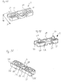
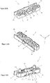
- FIGS. 1A to 1C show different views of the hold-down device 2 according to the invention.
- This hold-down device 2 is designed essentially as a rectangular and one-piece plastic injection-molded part, the longitudinal direction of which extends in a Cartesian coordinate system in the X-direction, the transverse direction of which extends in the Y-direction and the height of which extends in the Z- Direction extends.
- the direction of extension in the longitudinal direction along the X-axis is approximately three times as long as along the transverse direction along the Y-axis.
- the hold-down device has a total of 2 dimensions of 38 millimeters x 9 millimeters x 5 Millimeters (LxWxH).
- This hold-down device 2 has a through opening 2A for a fastening screw 6 in the middle.
- This through-opening 2A is formed in the center of the hold-down device 2 in a plate-shaped screw section, which in the present case forms the central part of the hold-down surface lying in the XY plane.
- the surface of this plate-shaped section is also lowered by about half the height of the hold-down device 2 compared to the remaining surface of the hold-down device 2 so that the screw head does not protrude beyond the upper end of the hold-down device 2 in the installed position.
- this plate-shaped, central screw section which in the installed position with its underside represents the essential part of the hold-down surface for applying the main contact pressure acting in the installed position in the Z-direction, extend in the longitudinal direction, i.e. radially protruding from the through-opening 2A, two integrally molded longitudinal arms 2B, 2C which in this respect are also part of the hold-down area.
- these longitudinal arms 2B, 2C are each T-shaped and thus extend in the Y-direction transverse arms 2D, 2E, which thus extend both in the Y-direction to an outside and against the Y-direction to a Extend inside.
- An inner clamping surface 2F is formed in one piece on these transverse arms 2D, 2E on the inside, which extends along the entire longitudinal axis of the hold-down device 2 and in the middle at the upper end has an integrally formed inner latching lug 2G with a curvature at the top, extending over approximately half the height the locking surface of this inner locking lug 2G extends in the Z direction from the upper end of the hold-down device 2, offset downwards, parallel to the Y-axis, approximately in the middle of the height of the hold-down device 2.
- This inner clamping surface 2F is spaced apart from the longitudinal arms 2B, 2C via the transverse arms 2D, 2E and is thus designed to be elastic in the longitudinal direction in order to to be able to easily connect the inner locking lug 2G to the complementary clamping component and to be able to detach it therefrom.
- this inner clamping surface 2F thus forms a first fixing element of the hold-down device 2, which in the installed position acts on the inside of the hold-down device 2.
- This inner clamping surface 2F is used in the present case for fastening a light-permeable and light-directing surface having primary optics 10, which spans the LED strip like a bridge in the installed position.
- a second fixing element of the hold-down device 2 is formed by elastic and self-contained arched sections which are integrally formed on the transverse arms 2D, 2E and which extend towards one another from the front ends to form outer clamping surfaces 2H, 21.
- the material thickness of the inner walls of these elastic arched sections is approximately half as thick as the outer clamping surfaces 2H, 2I to achieve the required elasticity and thus the implementation of the component-optimized and adapted latching forces for fastening a clamping component, in this case the secondary optics 12 surrounding the LED assembly according to FIGS Figures 10-14 .
- Each outer clamping surface 2H, 2I has outer locking lugs 2J, 2K formed in one piece on the outer clamping surfaces 2H, 2I, which initially encompass an arcuate run-up bevel extending from the upper end of the hold-down device 2 and then offset downwards in a Z-direction from the upper end and the latching surface extending parallel to the Y direction pass over.
- the hold-down 2 On its underside, the hold-down 2 has two positioning means designed as pins 2L, 2M and integrally formed, which extend downward in the Z direction transversely to the hold-down surface spanned by the XY planes and with which the hold-down 2 can be inserted into holes in the LED Board 4 or the joining partner can be inserted in a position-fixing manner.
- the joining partner includes a defined hole pattern at defined target positions and the LED board also includes a corresponding hole pattern into which the positioning means of the hold-down devices 2 can be inserted in a position-fixing and positioning manner. In the installation position, the individual components of the LED assembly are precisely positioned and fixed in relation to one another and in relation to the joint partner.
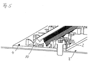
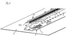
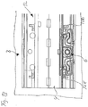
- Figure 2 shows an LED assembly comprising an elongated LED board 4, a luminaire housing 8 or a device carrier arranged underneath and a primary optics 10 fixed in position on the LED board 4 by the hold-down device 2 plugged into the LED board 4, which are offset outward on the LED board 4 parallel to the longitudinal direction of the LEDs in the center of the LED board.
- the hold-down 2 After the hold-down 2 has been plugged onto the LED board 4, in which case two hold-downs 2 are arranged on one side of the primary optics 10 and one hold-down 2 is arranged in the middle between the two on the opposite side of the primary optics 10 the hold-down device 2 is screwed to the lamp housing 8 by means of fastening screws 6.
- the primary optics 10 designed as a one-piece plastic injection-molded part, are connected to the LED circuit board 4 by simply pressing on the primary optics 10.
- locking surfaces on the primary optics reach under the inner locking lugs 2G of the hold-down devices 2 and, in the locking position, lie flat below the contact surface of the inner locking lugs 2G.
- the primary optics thus surrounds the LEDs of the LED board 4 extending in the longitudinal direction in a dome-like manner, the primary optics 10 additionally having reflective surfaces adapted to the application for directing light.
- FIG. 6 shows the primary optics 10 to the Outer tabs 10A, 10B extending in the longitudinal direction each have engaging hooks 10C, 10D designed complementary to the hold-downs 2, which in the installed position engage in front-side recesses 2N, 20 of the hold-down 2, so that in the installed position as shown in FIG Figure 7 the inner locking lug 2G of the hold-down 2 rests on a locking lug plateau 10E and the engagement hooks 10C, 10D, which are spaced approximately the length of the hold-down 2 along the longitudinal axis of the primary optics 10, engage with their protruding legs into the recesses 2N, 20 of the hold-down 2 to accomplish this the positional fixation.
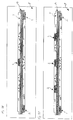
- the Figures 10-14 show the attachment of secondary optics 12 covering the LED assembly by means of hold-down devices 2 according to the invention.
- the translucent secondary optics 12 bridges the LED board 4 like a bridge from longitudinal side to longitudinal side and has an upwardly curved, dome-shaped dome in the middle area, under which the primary optics 10 are arranged, but which are in the Figures 10 to 14 is not shown for better illustration.
- the attachment of the secondary optics 12 takes place in turn by means of complementary locking means formed between the hold-down devices 2 and the secondary optics, which in the present embodiment on the hold-down devices 2 and in this case to the outer locking lugs 2J, 2K on the outer locking surfaces 2H, 2I complementary in vertical webs of the secondary optics formed locking holes 12A, 12B, in which the outer locking lugs 2J, 2K engage.
- position fixing elements designed as centering brackets 12C, 12D are provided which, in the installed position, engage in the front openings 2N, 20 of the hold-down devices 2 in a position-fixing manner so that the width of the front openings 2N, 20 is selected to be so large that centering elements of both the primary optics 10 and the secondary optics 12 can be received in them.
- FIGS 15A to 15C show a further embodiment of a hold-down device 2 'designed according to the invention, which is essentially identical to that in FIG Figures 1A to 1C specified hold-down device is constructed. Only the difference to the hold-down device described above is discussed below. This difference relates to the design of the hold-down device on the outside in the area of the through opening 2A. A further outer clamping surface 2Q, which runs parallel to the adjacent clamping surfaces 2H and 2I, is formed in the middle, outer region of the hold-down device.
- the modified hold-down 2 ' in contrast to the first hold-down 2, has a further outer locking lug 2P in the middle, outer area on the outer clamping surface 2Q, which runs in the longitudinal direction of the holding-down 2' in alignment with the adjacent outer locking lugs 2K and 2J.
- the locking surfaces 2J_a, 2K_a and 2P_a of the specified outer locking lugs lie in one plane.
- the outer locking lugs 2K and 2J are designed to be resilient, while the outer locking lug 2P is rigid, since it is arranged on a rigid outer surface 2Q.
- the longitudinal extent of the outer latching lug 2Q is at least twice as long the longitudinal extension of the outer locking lugs 2K and 2J.
- the hold-down devices 2, 2 'designed according to the invention are designed with the outer outer clamping surfaces 2H, 2I or 2H, 2I, 2Q and the outer locking lugs 2J, 2K or 2J, 2K and 2P in order to create a look on the outside of the hold-down device like that in the Figures 10 to 14 specified secondary optics, or another optics such as a cover optics, in particular to hold or attach a diffuser.
- the ones in the Figures 10 to 14 specified secondary optics is usually designed as an injection molded part, which is held by the hold-down device on its outside as described.
- the functionality of the hold-down device according to the invention is not restricted to this.
- the hold-down devices 2, 2 'described can also be used to fasten optics, in particular cover optics, which are produced by an extrusion or extrusion process.
- cover optics which are produced by an extrusion or extrusion process.
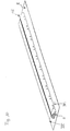
- cover 13 shows Figure 16 in an end view parallel to the longitudinal axis. It can be seen that the U-shaped cover in the area of the lower legs has a bulge acting as an undercut towards the outside, such that a shoulder surface 13B is formed over the entire longitudinal extent.
- stop 13A Its inwardly directed, rounded edge forms a stop 13A, this stop and the shoulder surface interacting with the clamping surfaces 2I, 2H, 2Q or the locking surfaces 2J_a, 2K_a and 2P_a of the hold-down device 2 or 2 'to hold the cover, which is explained below will be discussed in more detail.
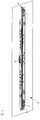
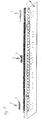
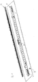
- Figure 17 shows an LED assembly comprising an elongated LED board 4, a luminaire housing 8 or a device carrier arranged underneath, wherein, as described above, the holding-down device attaches the LED board 4 to the lamp housing 8 or the device carrier.
- the LED assembly shown comprises a cover optic 13 which covers the LED circuit board 4 and encloses all of the longitudinally arranged hold-down devices 2 ', the attachment of the cover optics, designed here as a diffuser cover, to the hold-down devices 2' not being visible.
- Figure 18 shows the fastening or installation state between the optical cover 13 and the hold-down devices 2 '.
- the outer latching lugs 2J, 2K and 2P engage in the shoulder running longitudinally on the inside of the cover optics 13, in such a way that the latching surfaces 2J_a, 2K_a and 2P_a each come to rest on the shoulder surface 13B of the cover.
- the cover optics 13 is located on its side legs when installed in a slightly pretensioned state, such that the longitudinal stop 13A of the cover optics rests against the respective clamping surfaces 2H, 2Q and 2I.
- the described attachment of the cover optics to the hold-downs has the advantage that no form fit is set in the longitudinal direction between the hold-downs and the cover in the installed state, so that a change in length of the cover optics caused by temperature fluctuations cannot lead to destructive stresses within the cover optics, since between the Hold-downs and the cover optics alone a frictional connection is set.
- the LED assembly shown is particularly suitable for designing luminaires that are very long in the longitudinal direction.
- Both the hold-down devices 2 and the modified hold-down devices 2 ′ are designed for fastening the cover optics or the diffuser 13.
- a fastening of the cover 13 that is insensitive to the action of external forces can be provided due to the rigid outer latching lug 2P.
- the optical cover 13 To bring the optical cover 13 into engagement with the hold-down devices 2 'arranged in the longitudinal direction of both side legs and spaced apart, the optical cover 13 is first brought into engagement on one side leg with the associated outer latching lugs 2J, 2K and 2P of the assigned hold-down devices over the entire length of one side, for this purpose, the other side leg of the optics is pivoted out of its later installation position. Thereafter, the optical cover 13, or its free side leg, is pivoted down around the attached longitudinal side, this side leg, which has not yet been engaged, is bent slightly outward due to the elasticity of the material until the second side leg is also in its vertical end position. The outward force applied to the second leg can then be canceled.
- the cover can also be moved vertically downwards, aligned horizontally with respect to the LED circuit board, whereby both side legs are resiliently pressed outwards by the support on the hold-downs, whereby the outer locking lugs 2J, 2K and 2P the hold-down device 2 'come to lie in the undercut and both side legs of the cover 13 snap back again.
- the optics can also be configured in one or more parts.
Landscapes
- Engineering & Computer Science (AREA)
- General Engineering & Computer Science (AREA)
- Fastening Of Light Sources Or Lamp Holders (AREA)
Applications Claiming Priority (4)
| Application Number | Priority Date | Filing Date | Title |
|---|---|---|---|
| DE102013214620.5A DE102013214620A1 (de) | 2013-07-26 | 2013-07-26 | Niederhalter |
| DE202014100922.1U DE202014100922U1 (de) | 2013-07-26 | 2014-02-28 | Niederhalter |
| PCT/EP2014/065732 WO2015011144A1 (fr) | 2013-07-26 | 2014-07-22 | Élément d'appui |
| EP14741639.0A EP3025095A1 (fr) | 2013-07-26 | 2014-07-22 | Élément d'appui |
Related Parent Applications (1)
| Application Number | Title | Priority Date | Filing Date |
|---|---|---|---|
| EP14741639.0A Division EP3025095A1 (fr) | 2013-07-26 | 2014-07-22 | Élément d'appui |
Publications (2)
| Publication Number | Publication Date |
|---|---|
| EP3922909A1 true EP3922909A1 (fr) | 2021-12-15 |
| EP3922909B1 EP3922909B1 (fr) | 2023-08-30 |
Family
ID=51899916
Family Applications (2)
| Application Number | Title | Priority Date | Filing Date |
|---|---|---|---|
| EP14741639.0A Withdrawn EP3025095A1 (fr) | 2013-07-26 | 2014-07-22 | Élément d'appui |
| EP21187742.8A Active EP3922909B1 (fr) | 2013-07-26 | 2014-07-22 | Ensemble del avec des serre-flans |
Family Applications Before (1)
| Application Number | Title | Priority Date | Filing Date |
|---|---|---|---|
| EP14741639.0A Withdrawn EP3025095A1 (fr) | 2013-07-26 | 2014-07-22 | Élément d'appui |
Country Status (3)
| Country | Link |
|---|---|
| EP (2) | EP3025095A1 (fr) |
| DE (2) | DE102013214620A1 (fr) |
| WO (1) | WO2015011144A1 (fr) |
Families Citing this family (6)
| Publication number | Priority date | Publication date | Assignee | Title |
|---|---|---|---|---|
| DE102016109371A1 (de) * | 2016-05-20 | 2017-11-23 | Siteco Beleuchtungstechnik Gmbh | Leuchte mit LED-Leiterplatte auf Blechträger |
| DE202017105600U1 (de) | 2017-09-15 | 2018-12-18 | Rp-Technik Gmbh | Linsenhalter, insbesondere für eine Kombinationslinse einer Beleuchtungsoptik, sowie Leuchte mit einem entsprechenden Linsenhalter |
| DE102018105004A1 (de) | 2018-03-05 | 2019-09-05 | Vossloh-Schwabe Deutschland Gmbh | Leuchte |
| EP3653927B1 (fr) * | 2018-11-15 | 2022-01-19 | TRILUX GmbH & Co. KG | Luminaire pourvu de couvercle maintenu par l'adaptateur |
| DE202019103525U1 (de) * | 2019-06-26 | 2020-10-28 | Thorn Lighting Limited | Befestigungsclip |
| CN110736078B (zh) * | 2019-10-21 | 2025-07-04 | 中节能晶和科技有限公司 | 一种透镜面盖的装配制具 |
Citations (7)
| Publication number | Priority date | Publication date | Assignee | Title |
|---|---|---|---|---|
| JPS59134011A (ja) * | 1983-01-20 | 1984-08-01 | Potsupuribetsuto Fastener Kk | 窓ガラス及びモ−ル固定用クリツプ |
| US20090207617A1 (en) * | 2008-02-20 | 2009-08-20 | Merchant Viren B | Light emitting diode (led) connector clip |
| JP2010003683A (ja) * | 2008-05-19 | 2010-01-07 | Katsukiyo Morii | 発光素子方式照明灯 |
| DE102009043760A1 (de) | 2009-09-30 | 2011-03-31 | Trilux Gmbh & Co. Kg | Befestigungselement für plattenförmige Bauteile aneinander, insbesondere für eine LED-Platine an einem Kühlkörper |
| DE202012001835U1 (de) * | 2012-02-24 | 2012-03-23 | Bjb Gmbh & Co. Kg | Anschlusselement für eine auf einer Platine angeordnete lichtemmitierende Diode (LED) |
| EP2489931A2 (fr) * | 2011-02-16 | 2012-08-22 | Toshiba Lighting & Technology Corporation | Luminaire |
| US20130044475A1 (en) * | 2011-08-19 | 2013-02-21 | Lsi Industries, Inc. | Luminaires and lighting structures |
Family Cites Families (4)
| Publication number | Priority date | Publication date | Assignee | Title |
|---|---|---|---|---|
| US4630422A (en) * | 1985-01-22 | 1986-12-23 | The Firestone Tire & Rubber Company | Penetrating roofing mechanical fastening sealing system and method |
| DE102006008807B4 (de) * | 2006-02-25 | 2010-10-14 | Semikron Elektronik Gmbh & Co. Kg | Anordnung mit einem Leistungshalbleitermodul und einem Kühlbauteil |
| US20100061092A1 (en) * | 2008-09-09 | 2010-03-11 | Fu Zhun Precision Industry (Shen Zhen) Co., Ltd. | Led lamp |
| DE102011055679B4 (de) * | 2011-11-24 | 2017-05-18 | Vossloh-Schwabe Deutschland Gmbh | Baugruppe für eine Leuchte mit einem Leuchtmittelträger und einem Schaltungsträger |
-
2013
- 2013-07-26 DE DE102013214620.5A patent/DE102013214620A1/de not_active Withdrawn
-
2014
- 2014-02-28 DE DE202014100922.1U patent/DE202014100922U1/de not_active Expired - Lifetime
- 2014-07-22 EP EP14741639.0A patent/EP3025095A1/fr not_active Withdrawn
- 2014-07-22 EP EP21187742.8A patent/EP3922909B1/fr active Active
- 2014-07-22 WO PCT/EP2014/065732 patent/WO2015011144A1/fr not_active Ceased
Patent Citations (7)
| Publication number | Priority date | Publication date | Assignee | Title |
|---|---|---|---|---|
| JPS59134011A (ja) * | 1983-01-20 | 1984-08-01 | Potsupuribetsuto Fastener Kk | 窓ガラス及びモ−ル固定用クリツプ |
| US20090207617A1 (en) * | 2008-02-20 | 2009-08-20 | Merchant Viren B | Light emitting diode (led) connector clip |
| JP2010003683A (ja) * | 2008-05-19 | 2010-01-07 | Katsukiyo Morii | 発光素子方式照明灯 |
| DE102009043760A1 (de) | 2009-09-30 | 2011-03-31 | Trilux Gmbh & Co. Kg | Befestigungselement für plattenförmige Bauteile aneinander, insbesondere für eine LED-Platine an einem Kühlkörper |
| EP2489931A2 (fr) * | 2011-02-16 | 2012-08-22 | Toshiba Lighting & Technology Corporation | Luminaire |
| US20130044475A1 (en) * | 2011-08-19 | 2013-02-21 | Lsi Industries, Inc. | Luminaires and lighting structures |
| DE202012001835U1 (de) * | 2012-02-24 | 2012-03-23 | Bjb Gmbh & Co. Kg | Anschlusselement für eine auf einer Platine angeordnete lichtemmitierende Diode (LED) |
Also Published As
| Publication number | Publication date |
|---|---|
| DE102013214620A1 (de) | 2015-01-29 |
| EP3922909B1 (fr) | 2023-08-30 |
| DE202014100922U1 (de) | 2014-10-28 |
| WO2015011144A1 (fr) | 2015-01-29 |
| EP3025095A1 (fr) | 2016-06-01 |
Similar Documents
| Publication | Publication Date | Title |
|---|---|---|
| EP3922909B1 (fr) | Ensemble del avec des serre-flans | |
| DE102007038787B4 (de) | Leuchtmodul für eine Halbleiterlichtquellen-Leuchte und Halbleiterlichtquellen-Leuchte | |
| DE102014213468A1 (de) | Leuchte, Anordnung für eine Rasterdecke, Verfahren zum Montieren einer Leuchte, Verfahren zum Demontieren einer Leuchte, sowie Demontagewerkzeug | |
| DE102010049605A1 (de) | Kastengehäuse und Herstellungsverfahren | |
| DE102019109676A1 (de) | Haltefeder für Leuchte | |
| EP3608588B1 (fr) | Ressort de maintien pour luminaire | |
| DE102007038788A1 (de) | Leuchtmodul für eine Halbleiterlichtquellen-Leuchte und Halbleiterlichtquellen-Leuchte | |
| AT14622U1 (de) | Leuchte bzw. Beleuchtungsanordnung mit länglichem Trägerelement und lösbar befestigbarem Leuchtmodul | |
| EP4354017A1 (fr) | Système de fixation pour une lampe, élément de fixation et lampe | |
| AT11164U1 (de) | Led-einbaumodul, beleuchtungsanordnung sowie decken- oder wandkonstruktion mit diesem led-einbaumodul | |
| DE102013101736A1 (de) | Anordnung zur Befestigung und Positionierung von Relais | |
| EP4002615A1 (fr) | Fixation d'un couplage pour un système de bande lumineuse | |
| WO2007121834A1 (fr) | Système de fixation, notamment pour lampes | |
| DE102023101534B3 (de) | Haltevorrichtung, elektronische Anordnung und Verfahren zum Herstellen einer elektronischen Anordnung für ein Kraftfahrzeug | |
| EP3088796B1 (fr) | Rail profile destine au positionnement de modules a del dans des condensateurs lumineux | |
| EP3855069B1 (fr) | Système de fermeture de bande lumineuse et fil | |
| DE102019109662A1 (de) | Haltefeder | |
| EP3772607B1 (fr) | Luminaire à prise d'atténuation | |
| EP2624362B1 (fr) | Agencement d'antennes et procédé de fonctionnement d'un tel agencement d'antennes | |
| EP4350211A1 (fr) | Bande lumineuse avec accouplement détachable | |
| DE102023119082A1 (de) | Lichtband mit Kratzfederkupplung | |
| AT513711B1 (de) | Reflektor für eine Leuchte, insbesondere für eine Deckeneinbauleuchte | |
| DE102023119091A1 (de) | Lichtband mit lösbarer Kupplung | |
| EP2711623B1 (fr) | Agencement de verrouillage pour une lampe et lampe dotée d'un agencement de verrouillage | |
| DE102013202909B4 (de) | Leuchtengehäuse mit Ausstanzung für Schnellanschlusssystem |
Legal Events
| Date | Code | Title | Description |
|---|---|---|---|
| PUAI | Public reference made under article 153(3) epc to a published international application that has entered the european phase |
Free format text: ORIGINAL CODE: 0009012 |
|
| STAA | Information on the status of an ep patent application or granted ep patent |
Free format text: STATUS: THE APPLICATION HAS BEEN PUBLISHED |
|
| AC | Divisional application: reference to earlier application |
Ref document number: 3025095 Country of ref document: EP Kind code of ref document: P |
|
| AK | Designated contracting states |
Kind code of ref document: A1 Designated state(s): AL AT BE BG CH CY CZ DE DK EE ES FI FR GB GR HR HU IE IS IT LI LT LU LV MC MK MT NL NO PL PT RO RS SE SI SK SM TR |
|
| B565 | Issuance of search results under rule 164(2) epc |
Effective date: 20211117 |
|
| STAA | Information on the status of an ep patent application or granted ep patent |
Free format text: STATUS: REQUEST FOR EXAMINATION WAS MADE |
|
| 17P | Request for examination filed |
Effective date: 20220615 |
|
| RBV | Designated contracting states (corrected) |
Designated state(s): AL AT BE BG CH CY CZ DE DK EE ES FI FR GB GR HR HU IE IS IT LI LT LU LV MC MK MT NL NO PL PT RO RS SE SI SK SM TR |
|
| GRAP | Despatch of communication of intention to grant a patent |
Free format text: ORIGINAL CODE: EPIDOSNIGR1 |
|
| STAA | Information on the status of an ep patent application or granted ep patent |
Free format text: STATUS: GRANT OF PATENT IS INTENDED |
|
| RIC1 | Information provided on ipc code assigned before grant |
Ipc: F21Y 115/10 20160101ALI20230222BHEP Ipc: F21Y 103/10 20160101ALI20230222BHEP Ipc: F21V 3/00 20060101ALI20230222BHEP Ipc: F16B 5/06 20060101ALI20230222BHEP Ipc: F16B 13/00 20060101ALI20230222BHEP Ipc: F21V 19/00 20060101ALI20230222BHEP Ipc: F21V 17/16 20060101AFI20230222BHEP |
|
| INTG | Intention to grant announced |
Effective date: 20230314 |
|
| GRAS | Grant fee paid |
Free format text: ORIGINAL CODE: EPIDOSNIGR3 |
|
| P01 | Opt-out of the competence of the unified patent court (upc) registered |
Effective date: 20230527 |
|
| GRAA | (expected) grant |
Free format text: ORIGINAL CODE: 0009210 |
|
| STAA | Information on the status of an ep patent application or granted ep patent |
Free format text: STATUS: THE PATENT HAS BEEN GRANTED |
|
| AC | Divisional application: reference to earlier application |
Ref document number: 3025095 Country of ref document: EP Kind code of ref document: P |
|
| AK | Designated contracting states |
Kind code of ref document: B1 Designated state(s): AL AT BE BG CH CY CZ DE DK EE ES FI FR GB GR HR HU IE IS IT LI LT LU LV MC MK MT NL NO PL PT RO RS SE SI SK SM TR |
|
| REG | Reference to a national code |
Ref country code: GB Ref legal event code: FG4D Free format text: NOT ENGLISH |
|
| REG | Reference to a national code |
Ref country code: CH Ref legal event code: EP |
|
| REG | Reference to a national code |
Ref country code: DE Ref legal event code: R096 Ref document number: 502014016678 Country of ref document: DE |
|
| REG | Reference to a national code |
Ref country code: IE Ref legal event code: FG4D Free format text: LANGUAGE OF EP DOCUMENT: GERMAN |
|
| REG | Reference to a national code |
Ref country code: LT Ref legal event code: MG9D |
|
| REG | Reference to a national code |
Ref country code: NL Ref legal event code: MP Effective date: 20230830 |
|
| PG25 | Lapsed in a contracting state [announced via postgrant information from national office to epo] |
Ref country code: GR Free format text: LAPSE BECAUSE OF FAILURE TO SUBMIT A TRANSLATION OF THE DESCRIPTION OR TO PAY THE FEE WITHIN THE PRESCRIBED TIME-LIMIT Effective date: 20231201 |
|
| PG25 | Lapsed in a contracting state [announced via postgrant information from national office to epo] |
Ref country code: IS Free format text: LAPSE BECAUSE OF FAILURE TO SUBMIT A TRANSLATION OF THE DESCRIPTION OR TO PAY THE FEE WITHIN THE PRESCRIBED TIME-LIMIT Effective date: 20231230 |
|
| PG25 | Lapsed in a contracting state [announced via postgrant information from national office to epo] |
Ref country code: SE Free format text: LAPSE BECAUSE OF FAILURE TO SUBMIT A TRANSLATION OF THE DESCRIPTION OR TO PAY THE FEE WITHIN THE PRESCRIBED TIME-LIMIT Effective date: 20230830 Ref country code: RS Free format text: LAPSE BECAUSE OF FAILURE TO SUBMIT A TRANSLATION OF THE DESCRIPTION OR TO PAY THE FEE WITHIN THE PRESCRIBED TIME-LIMIT Effective date: 20230830 Ref country code: NO Free format text: LAPSE BECAUSE OF FAILURE TO SUBMIT A TRANSLATION OF THE DESCRIPTION OR TO PAY THE FEE WITHIN THE PRESCRIBED TIME-LIMIT Effective date: 20231130 Ref country code: LV Free format text: LAPSE BECAUSE OF FAILURE TO SUBMIT A TRANSLATION OF THE DESCRIPTION OR TO PAY THE FEE WITHIN THE PRESCRIBED TIME-LIMIT Effective date: 20230830 Ref country code: LT Free format text: LAPSE BECAUSE OF FAILURE TO SUBMIT A TRANSLATION OF THE DESCRIPTION OR TO PAY THE FEE WITHIN THE PRESCRIBED TIME-LIMIT Effective date: 20230830 Ref country code: IS Free format text: LAPSE BECAUSE OF FAILURE TO SUBMIT A TRANSLATION OF THE DESCRIPTION OR TO PAY THE FEE WITHIN THE PRESCRIBED TIME-LIMIT Effective date: 20231230 Ref country code: HR Free format text: LAPSE BECAUSE OF FAILURE TO SUBMIT A TRANSLATION OF THE DESCRIPTION OR TO PAY THE FEE WITHIN THE PRESCRIBED TIME-LIMIT Effective date: 20230830 Ref country code: GR Free format text: LAPSE BECAUSE OF FAILURE TO SUBMIT A TRANSLATION OF THE DESCRIPTION OR TO PAY THE FEE WITHIN THE PRESCRIBED TIME-LIMIT Effective date: 20231201 Ref country code: FI Free format text: LAPSE BECAUSE OF FAILURE TO SUBMIT A TRANSLATION OF THE DESCRIPTION OR TO PAY THE FEE WITHIN THE PRESCRIBED TIME-LIMIT Effective date: 20230830 |
|
| PG25 | Lapsed in a contracting state [announced via postgrant information from national office to epo] |
Ref country code: PL Free format text: LAPSE BECAUSE OF FAILURE TO SUBMIT A TRANSLATION OF THE DESCRIPTION OR TO PAY THE FEE WITHIN THE PRESCRIBED TIME-LIMIT Effective date: 20230830 Ref country code: NL Free format text: LAPSE BECAUSE OF FAILURE TO SUBMIT A TRANSLATION OF THE DESCRIPTION OR TO PAY THE FEE WITHIN THE PRESCRIBED TIME-LIMIT Effective date: 20230830 |
|
| PG25 | Lapsed in a contracting state [announced via postgrant information from national office to epo] |
Ref country code: ES Free format text: LAPSE BECAUSE OF FAILURE TO SUBMIT A TRANSLATION OF THE DESCRIPTION OR TO PAY THE FEE WITHIN THE PRESCRIBED TIME-LIMIT Effective date: 20230830 |
|
| PG25 | Lapsed in a contracting state [announced via postgrant information from national office to epo] |
Ref country code: SM Free format text: LAPSE BECAUSE OF FAILURE TO SUBMIT A TRANSLATION OF THE DESCRIPTION OR TO PAY THE FEE WITHIN THE PRESCRIBED TIME-LIMIT Effective date: 20230830 Ref country code: RO Free format text: LAPSE BECAUSE OF FAILURE TO SUBMIT A TRANSLATION OF THE DESCRIPTION OR TO PAY THE FEE WITHIN THE PRESCRIBED TIME-LIMIT Effective date: 20230830 Ref country code: ES Free format text: LAPSE BECAUSE OF FAILURE TO SUBMIT A TRANSLATION OF THE DESCRIPTION OR TO PAY THE FEE WITHIN THE PRESCRIBED TIME-LIMIT Effective date: 20230830 Ref country code: EE Free format text: LAPSE BECAUSE OF FAILURE TO SUBMIT A TRANSLATION OF THE DESCRIPTION OR TO PAY THE FEE WITHIN THE PRESCRIBED TIME-LIMIT Effective date: 20230830 Ref country code: DK Free format text: LAPSE BECAUSE OF FAILURE TO SUBMIT A TRANSLATION OF THE DESCRIPTION OR TO PAY THE FEE WITHIN THE PRESCRIBED TIME-LIMIT Effective date: 20230830 Ref country code: CZ Free format text: LAPSE BECAUSE OF FAILURE TO SUBMIT A TRANSLATION OF THE DESCRIPTION OR TO PAY THE FEE WITHIN THE PRESCRIBED TIME-LIMIT Effective date: 20230830 Ref country code: SK Free format text: LAPSE BECAUSE OF FAILURE TO SUBMIT A TRANSLATION OF THE DESCRIPTION OR TO PAY THE FEE WITHIN THE PRESCRIBED TIME-LIMIT Effective date: 20230830 Ref country code: PT Free format text: LAPSE BECAUSE OF FAILURE TO SUBMIT A TRANSLATION OF THE DESCRIPTION OR TO PAY THE FEE WITHIN THE PRESCRIBED TIME-LIMIT Effective date: 20240102 |
|
| PG25 | Lapsed in a contracting state [announced via postgrant information from national office to epo] |
Ref country code: IT Free format text: LAPSE BECAUSE OF FAILURE TO SUBMIT A TRANSLATION OF THE DESCRIPTION OR TO PAY THE FEE WITHIN THE PRESCRIBED TIME-LIMIT Effective date: 20230830 |
|
| REG | Reference to a national code |
Ref country code: DE Ref legal event code: R097 Ref document number: 502014016678 Country of ref document: DE |
|
| PLBE | No opposition filed within time limit |
Free format text: ORIGINAL CODE: 0009261 |
|
| STAA | Information on the status of an ep patent application or granted ep patent |
Free format text: STATUS: NO OPPOSITION FILED WITHIN TIME LIMIT |
|
| PG25 | Lapsed in a contracting state [announced via postgrant information from national office to epo] |
Ref country code: SI Free format text: LAPSE BECAUSE OF FAILURE TO SUBMIT A TRANSLATION OF THE DESCRIPTION OR TO PAY THE FEE WITHIN THE PRESCRIBED TIME-LIMIT Effective date: 20230830 |
|
| 26N | No opposition filed |
Effective date: 20240603 |
|
| PG25 | Lapsed in a contracting state [announced via postgrant information from national office to epo] |
Ref country code: BG Free format text: LAPSE BECAUSE OF FAILURE TO SUBMIT A TRANSLATION OF THE DESCRIPTION OR TO PAY THE FEE WITHIN THE PRESCRIBED TIME-LIMIT Effective date: 20230830 |
|
| PG25 | Lapsed in a contracting state [announced via postgrant information from national office to epo] |
Ref country code: BG Free format text: LAPSE BECAUSE OF FAILURE TO SUBMIT A TRANSLATION OF THE DESCRIPTION OR TO PAY THE FEE WITHIN THE PRESCRIBED TIME-LIMIT Effective date: 20230830 |
|
| PG25 | Lapsed in a contracting state [announced via postgrant information from national office to epo] |
Ref country code: MC Free format text: LAPSE BECAUSE OF FAILURE TO SUBMIT A TRANSLATION OF THE DESCRIPTION OR TO PAY THE FEE WITHIN THE PRESCRIBED TIME-LIMIT Effective date: 20230830 |
|
| PG25 | Lapsed in a contracting state [announced via postgrant information from national office to epo] |
Ref country code: LU Free format text: LAPSE BECAUSE OF NON-PAYMENT OF DUE FEES Effective date: 20240722 |
|
| PG25 | Lapsed in a contracting state [announced via postgrant information from national office to epo] |
Ref country code: LU Free format text: LAPSE BECAUSE OF NON-PAYMENT OF DUE FEES Effective date: 20240722 |
|
| PG25 | Lapsed in a contracting state [announced via postgrant information from national office to epo] |
Ref country code: BE Free format text: LAPSE BECAUSE OF NON-PAYMENT OF DUE FEES Effective date: 20240731 |
|
| REG | Reference to a national code |
Ref country code: BE Ref legal event code: MM Effective date: 20240731 |
|
| PG25 | Lapsed in a contracting state [announced via postgrant information from national office to epo] |
Ref country code: IE Free format text: LAPSE BECAUSE OF NON-PAYMENT OF DUE FEES Effective date: 20240722 |
|
| PGFP | Annual fee paid to national office [announced via postgrant information from national office to epo] |
Ref country code: DE Payment date: 20250923 Year of fee payment: 12 |
|
| PGFP | Annual fee paid to national office [announced via postgrant information from national office to epo] |
Ref country code: GB Payment date: 20250724 Year of fee payment: 12 |
|
| PGFP | Annual fee paid to national office [announced via postgrant information from national office to epo] |
Ref country code: AT Payment date: 20250721 Year of fee payment: 12 Ref country code: FR Payment date: 20250723 Year of fee payment: 12 |
|
| PGFP | Annual fee paid to national office [announced via postgrant information from national office to epo] |
Ref country code: CH Payment date: 20250801 Year of fee payment: 12 |
|
| PG25 | Lapsed in a contracting state [announced via postgrant information from national office to epo] |
Ref country code: CY Free format text: LAPSE BECAUSE OF FAILURE TO SUBMIT A TRANSLATION OF THE DESCRIPTION OR TO PAY THE FEE WITHIN THE PRESCRIBED TIME-LIMIT; INVALID AB INITIO Effective date: 20140722 |
|
| PG25 | Lapsed in a contracting state [announced via postgrant information from national office to epo] |
Ref country code: HU Free format text: LAPSE BECAUSE OF FAILURE TO SUBMIT A TRANSLATION OF THE DESCRIPTION OR TO PAY THE FEE WITHIN THE PRESCRIBED TIME-LIMIT; INVALID AB INITIO Effective date: 20140722 |