EP3922977B1 - Verfahren zur bestimmung einer eigenschaft eines partikels in einem medium - Google Patents
Verfahren zur bestimmung einer eigenschaft eines partikels in einem medium Download PDFInfo
- Publication number
- EP3922977B1 EP3922977B1 EP20178798.3A EP20178798A EP3922977B1 EP 3922977 B1 EP3922977 B1 EP 3922977B1 EP 20178798 A EP20178798 A EP 20178798A EP 3922977 B1 EP3922977 B1 EP 3922977B1
- Authority
- EP
- European Patent Office
- Prior art keywords
- light beam
- electric field
- particle
- intensity
- determined
- Prior art date
- Legal status (The legal status is an assumption and is not a legal conclusion. Google has not performed a legal analysis and makes no representation as to the accuracy of the status listed.)
- Active
Links
Images


Classifications
-
- G—PHYSICS
- G01—MEASURING; TESTING
- G01N—INVESTIGATING OR ANALYSING MATERIALS BY DETERMINING THEIR CHEMICAL OR PHYSICAL PROPERTIES
- G01N15/00—Investigating characteristics of particles; Investigating permeability, pore-volume or surface-area of porous materials
- G01N15/10—Investigating individual particles
- G01N15/14—Optical investigation techniques, e.g. flow cytometry
- G01N15/1434—Optical arrangements
-
- G—PHYSICS
- G01—MEASURING; TESTING
- G01N—INVESTIGATING OR ANALYSING MATERIALS BY DETERMINING THEIR CHEMICAL OR PHYSICAL PROPERTIES
- G01N15/00—Investigating characteristics of particles; Investigating permeability, pore-volume or surface-area of porous materials
- G01N15/02—Investigating particle size or size distribution
- G01N15/0205—Investigating particle size or size distribution by optical means
- G01N15/0211—Investigating a scatter or diffraction pattern
Definitions
- the present invention relates to a method for determining a property of at least one particle in a medium.
- the background of this invention lies in the field of observing a property of one or more particles in colloids such as emulsions, cell cultures and bacteria in a medium, for example to study bacterial onset of urinary tract infections.
- plastic particles in ocean water, impurities in liquid foods or pharmaceuticals, cells or their organelles in bodily fluids, or the like could be observed.
- the property can either be intrinsic to the particle like its size, shape, structure, propulsion mechanism, dry mass, etc. or related to the medium, like the particle's location, velocity or diffusion in the medium, etc.
- the property of several particles like their distribution, mutual distance, interaction, etc. in the medium can be determined.
- the background signal is induced by a portion of the light that is scattered in the medium, i.e., not by the particles but by other (usually smaller) bodies in the medium (e.g., by Mie-scattering), and impairs a contrast between light scattered by the particles and light not scattered by the particles.
- a method for determining a property of at least one particle in a medium comprising:
- the electric field of the light beam is generally complex-valued and, thus, can be described by its real and imaginary parts or by its amplitude and phase.
- the light beam has an intensity, i.e., a power per unit area, which is proportional to the square of the amplitude of the electric field.
- phase values which, according to the present method, are not determined conventionally from a phase of the scattered light beam only, but are determined both from the light beam scattered by the particles in the medium and from the light beam not scattered by the particles in the medium, yield a higher contrast.
- the higher contrast is also based on the determination of the intensity values, each of which is determined from the respective phase value and from the intensity of the first part of the light beam.
- the properties of even weakly scattering or small sized particles or of particles at high density in the medium can be resolved in the representation; moreover artefacts can be - largely - eliminated, and the properties of particles showing a lens effect are discriminated from their focal points, such that the property of the at least one particle in the medium can be determined more accurately.
- said positions may be distributed within the sample as desired, for example as a regular grid representing, e.g., adjoining cubic regions within the sample or as an irregular grid representing, e.g., arbitrarily formed spatial regions within the sample.
- said positions lie in virtual planes which are perpendicular to a direction of the second part of the light beam, and said step of computing is executed plane by plane along said direction.
- Such a distribution of positions allows to efficiently compute the electric field, and to determine the phase and intensity values plane by plane along the beam direction, i.e., in beam direction or in opposite direction.
- the electric field of the second part of the light beam may be estimated to have, at all positions within a respective plane, the same phase.
- the interference image carries information about both the first and the second part of the light beam.
- the interference image is normalised on the basis of a reference image of the coherent light beam without scattering by the at least one particle.
- the normalised interference image enables a more precise computing of the electric field of the first part and, consequently, a further improved determination of both the phase value and the intensity value and, thus, an enhanced contrast.
- the electric field of the second part of the light beam is estimated from a corresponding value of a reference image of the coherent light beam without scattering by the particles. This provides an easy and more accurate estimation of the electric field of the second part of the light beam.
- Said reference image may be generated in different ways as known in the art, e.g., as a low pass filtered version of the interference image, by repeating the steps of emitting and recording to obtain several interference images, an average of which is generated as the reference image, etc.
- the reference image is generated by emitting, with the light source, the coherent light beam without the sample of the medium containing the at least one particle, and recording, with the camera, the reference image thereof.
- the reference image is easily generated either with a sample of the medium, wherein the medium contains none of said particle(s), or without a sample, both of which options are comprised by the wording "without the sample of the medium containing the at least one particle".
- a particularly high contrast can be achieved, when, in said step of generating, for each of said positions, a minimum difference angle between a phase of said computed electric field and a phase of said estimated electric field is identified, and the phase value is determined as a portion of said difference angle.
- smaller difference angles between said phases can result in even smaller intensity values such that the contrast is further enhanced.
- the phase value is determined as a phase of a weighted sum of said computed electric field and said estimated electric field.
- a determination is simple, computationally cheap and requires only two weights to be determined, the weight of the computed electric field and the weight of the estimated electric field.
- the weights can, e.g., be determined iteratively or from prior experience to maximise contrast, to suppress the background signal, etc.
- the electric field of the second part of the light beam is estimated to be real and to have an amplitude of one which is particularly accurate in the embodiment with a normalised interference image.
- the first and second parts of the light beam are weighted equally, such that the intensity values can easily be determined to be smaller at positions where the difference angles between the phases of the computed and estimated electric fields are smaller; as a consequence thereof, the contrast may further be enhanced.
- the intensity value is efficiently calculated.
- the additional phase shift of ⁇ further attenuates the background signal such that light scattered by the particles can more easily be distinguished from light not scattered by the particles in the intensity values of the representation.
- an intensity threshold is calculated using said intensity values, preferably as an average of two or more of said intensity values, and when, in said step of determining, for each of said positions, neither the phase value nor the intensity value comprised by the representation for that position are used when the intensity value is smaller than the calculated intensity threshold.
- this allows for a faster determination of the particle distribution due to a reduced amount of data to be considered.
- the intensity threshold may be calculated as known to the skilled person, e.g., as a predetermined percentage of a (general, typical, expected, or currently determined) maximum intensity value, as an average of intensity values at several positions, as an overall average of all intensity values of the representation, etc.
- two or more coherent light beams are emitted, wherein said steps of recording, computing and generating are performed for each of the two or more coherent light beams to obtain a respective representation of the sample, and wherein said property is determined using the obtained two or more representations.
- said property can be determined more accurately from the additional information provided by the two or more representations.
- properties like particle velocities, particle diffusion, electrophoresis, etc. can be studied if emissions are time-delayed.
- the two or more representations are averaged to an averaged representation, and, in said step of determining, said property is determined from the averaged representation.
- each of the two or more coherent light beams is emitted with a respective one of two or more light sources.
- the sample can be irradiated under different angles which provides additional information, e.g., further easing a distinction of a particle's location which is common to all light beams from the particle's foci each of which is differently located for these light beams.
- This allows to apply techniques to increase the resolution of the representation, e.g., by multiplexing spatial frequency bands, known in the art as "super-resolution”.
- the coherent light beams can be emitted simultaneously and, thus, easily be correlated.
- each of the two or more coherent light beams is emitted at a different frequency. This allows to obtain a coloured and/or more accurate particle distribution, e.g., by averaging the two or more representations. Moreover, additional information about particles' properties such as their colour, dispersion properties, colour of their secretions, etc. is produced.
- three coherent light beams are emitted, and the respective frequencies of the three coherent light beams correspond to the colours red, green and blue.
- RGB-sensors red, green and blue light
- further particle properties e.g., an oxidation state of the iron in a haemoglobin particle, a colour of a secretion of a particle like a toxin, etc., can be determined by the coloured representation (s) .
- Fig. 1 shows an inline interferometer 1 comprising a light source 2 and a camera 3.
- the inline interferometer 1 is used to determine a property of at least one (microscopic) particle P in a medium M, e.g., one or more particles' location(s), size(s), shape(s), structure(s), elasticity (elasticities), dry mass(es), secretions, velocity (velocities), propulsion mechanism(s), diffusion(s), shape(s) of vesicles and/or several particles' distribution, mutual distances, interaction, etc.
- a three-dimensional particle distribution 4 ( Fig. 2 ) of particles P in a medium M is determined.
- a sample 5 of the medium M containing the one or more particles P is provided between the light source 2 and the camera 3.
- the one or more particles P could be cells, bacteria, charged particles, micro plastics, organelles, etc.
- the medium M could be water, oil, a body fluid (e.g. blood), a solution, or the like.
- any particle P in any colloid may be analysed.
- the light source 2 emits a coherent light beam 6 to irradiate the provided sample 5.
- the light source 2 may be of any type that is capable of emitting a coherent light beam 6, for example a laser diode.
- a first part of the light beam 6 is scattered by the one or more particles P and, thereby, creates a scattered light beam 7.
- a second part of the light beam 6 is not scattered by the particles P and traverses the sample 5 as an unscattered light beam 8 in a beam direction 9.
- the scattered light beam 7 relates to scattering by the one or more particles P in the medium M whereas the unscattered light beam 8 has not been scattered by the particles P in the medium M.
- scattering can mean diffracting, refracting, or reflecting, and depends on the choice of interferometer 1 used, which in turn may depend on the nature of the particles P, e.g., their transparency, reflectivity, or refractivity, and of the medium M.
- the scattered light beam 7 and the unscattered light beam 8 interfere with each other.
- the camera 3 records an interference image 10 ( Fig. 2 ) of the scattered light beam 7 and the unscattered light beam 8.
- the camera 3 can, for the present purpose, be any analogue or digital camera, for example with a Complementary Metal-Oxide Semiconductor (CMOS) or a Charge Coupled Device (CCD) image sensor.
- CMOS Complementary Metal-Oxide Semiconductor
- CCD Charge Coupled Device
- both said scattered light beam 7 and said unscattered light beam 8 may, however, also be scattered in the medium M, e.g., by other (usually smaller) bodies (e.g. via the Tyndall Effect), and that this portion of the unscattered light beam 8 slightly deviates from the beam direction 9.
- said portions of the scattered and unscattered light beams 7, 8 result in an inevitable, though undesirable background signal that generally impairs the determination of the particle distribution 4 in the medium M.
- the interferometer 1 may comprise one or more further optical devices as known in the art of holographic microscopy, e.g., an attenuator ring to improve the signal to noise ratio, a microscope objective, a phase plate, one or more lenses (e.g., a diverging lens to magnify the interference image 10), or the like.
- the interferometer 1 can also be embodied as another type of interferometer than an inline interferometer, for example as an interferometer 1 utilizing beamsplitters.
- the interference image 10 recorded by the camera 3 is then forwarded to a processor 11 via an interface 12.
- the processor 11 processes the interference image 10 to obtain the property of the at least one particle P in the medium M (here: the three-dimensional particle distribution 4) therefrom as shall now be explained with reference to Figs. 2 - 5 .
- the camera 3 records the interference image 10 (in the example of Fig. 2 : based on an E. coli bacterium in Lysogeny broth) as a purely two-dimensional image
- this interference image 10 encodes both intensity and phase information of the light beam 6. This information allows the processor 11 to "reconstruct" the sample 5 of the medium M containing the particles P in three steps S 1 - S 3 .
- a first step S 1 the processor 11 computes an electric field E 1 of the first part of the light beam 6, i.e., of the scattered light beam 7, for each of a plurality of positions 13 from the interference image 10.
- the positions 13 are three-dimensionally distributed within the sample 5.
- the positions 13 lie in several virtual planes 14 1 , 14 2 , ..., generally 14 i , which are perpendicular to the beam direction 9 of the unscattered light beam 8.
- the positions 13 are identically arranged in each virtual plane 14 i ; however, this is optional.
- the positions 13 may be three-dimensionally distributed within the sample 5, e.g., in a regular grid arrangement representing adjoining cubic regions or in an irregular grid arrangement representing adjacent arbitrarily formed spatial regions.
- the processor 11 applies a reconstruction algorithm onto the interference image 10.
- the electric field E 1 of the scattered light beam 7 for each position 13 is complex-valued and, thus, its real and imaginary parts or its phase ⁇ 1 and amplitude, respectively, are computed.
- the processor 11 applies the reconstruction algorithm plane by plane in a direction 15 which is opposite to the beam direction 9.
- this is optional and other reconstruction algorithms may be applied.
- Multiple variants of such reconstruction algorithms are known in the art, for example forward or back propagation or projection algorithms, e.g., an inverse Radon transformation, a Fourier-domain reconstruction algorithm, an iterative reconstruction algorithm, etc.
- the processor 11 In a subsequent second step S 2 , the processor 11 generates a representation 16 of the sample 5 which covers all positions 13 and comprises, for each position 13, a respective phase value ⁇ ( Fig. 3 ) and a respective intensity value I ( Figs. 4 and 5 ).
- the phase value ⁇ represents a phase shift of the scattered light beam 7, which phase shift is induced by a scattering by the particles P only.
- the phase value ⁇ is determined from the electric field E 1 of the scattered light beam 7 at that position 13 and from an estimated electric field E 2 of the unscattered light beam 8 at that position 13.
- the electric field E 2 of the unscattered light beam 8 may be estimated as known in the art, i.a., from a measurement, as will be exemplified in detail further down.
- the intensity value I represents an intensity of the light beam 6.
- the intensity value I is determined from the intensity I 1 of the scattered light beam 7 computed for that position 13, e.g., as a square of the amplitude of the electric field E 1 , and from the phase value ⁇ determined for that position 13.
- the processor 11 determines the property of the at least one particle P in the medium M (here: the particle distribution 4) using the representation 16 of the sample 5 obtained in step S 2 . This is done by evaluating the determined intensity values I and/or the phase values ⁇ as known in the art. For instance, the intensity and/or phase values I, ⁇ and the respective positions 13, i.e., their three-dimensional coordinates in a given coordinate system 17, may be input to a pattern recognition algorithm, a neural network, etc.
- said property of the at least one particle P in the medium M may be determined with the processor 11 (in this embodiment: with the aid of the processor 11), e.g., by human inspection of a visualisation of the intensity values I of the representation 16, which visualisation is provided by the processor 11.
- both the phase value ⁇ and the intensity value I at each position 13 can be determined in different ways, as follows.
- a minimum difference angle ⁇ between the phase ⁇ 1 of the computed electric field E 1 and a phase ⁇ 2 of the estimated electric field E 2 is identified, i.e., that one of the two difference angles that is smaller than n. Then, the phase value ⁇ is determined as a portion of said difference angle ⁇ . This can be achieved in a variety of ways; for example, the phase value ⁇ may be determined as a predetermined portion, e.g., a half, of the identified minimum difference angle ⁇ .
- phase ⁇ 2 of the unscattered light beam 8 is estimated to be zero (which is usually the case by definition)
- the difference angle ⁇ and the computed phase ⁇ 1 of the scattered light beam 7 coincide.
- the electric fields E 1 and E 2 at each position 13 are blended to obtain a blended field E m a phase ⁇ m of which lies between the phases ⁇ 1 and ⁇ 2 of the computed and estimated electric fields E 1 and E 2 .
- the phase value ⁇ is determined as a difference of the phase ⁇ m of the blended field E m and one of said phases ⁇ 1 and ⁇ 2 .
- the phase value ⁇ is determined as a phase of a weighted sum of the computed electric field E 1 and the estimated electric field E 2 .
- the weights are, e.g., determined from known optical parameters of the particles P and/or the medium M, from iteratively maximising a contrast between high intensity values I and low intensity values I in the resulting representation 16, etc.
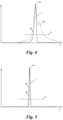
- the graphs in Figs. 4 and 5 show the intensity value I determined along the direction 15, i.e., along the z-axis of the coordinate system 17 ( Fig. 4 ), and in a perpendicular direction thereto (here: along the y-axis of the coordinate system 17, Fig. 5 ).
- dashed lines 19 depict an intensity value I determined according to the state of the art (here: based on an interference image recorded of a silica particle in "Milli Q" deionised water). As can be seen in Figs. 4 and 5 , the solid lines 18 are narrower about a respective maximum intensity I max and overall show less fluctuations.
- an additional phase shift ⁇ between said portion of the light beams 7, 8 scattered by the medium and the unscattered light beam 8 may be introduced and fitted, modelled, simulated, iterated, etc., to maximise a contrast between high intensity values I and low intensity values I in the representation 16.
- an intensity threshold I th is introduced prior to the processor's step S 3 .
- This intensity threshold I th is calculated using the intensity values I of the representation 16.
- the intensity values I and the phase values ⁇ for those positions 13 at which the determined intensity value I is smaller than the calculated intensity threshold I th shall not be used in step S 3 , e.g., not be input to the pattern recognition algorithm.
- the intensity threshold I th may, e.g., be a percentage of a maximum intensity value I max ( Figs. 4 and 5 ), a running average, an average of two or more, or even of all intensity values I comprised in the representation 16.
- a phase threshold may optionally be calculated for the same purpose and be used the same way as the intensity threshold I th .
- a reference image 20 of the coherent light beam 6 which has not been scattered by the at least one particle P, thus relating to the unscattered light beam 8, is generated.
- the reference image 20 may be generated in different ways known to the skilled person, e.g., as a lowpass filtered interference image 10.
- the reference image 20 is generated by emitting, with the light source 2, the coherent light beam 6 without the sample 5 of the medium M containing said at least one particle P, and recording, with the camera 3, the reference image 20 thereof.
- the wording "without the sample 5 of the medium M containing the particles P" either refers to no sample 5 at all or to a different sample comprising the medium M without the particles P being provided between the light source 2 and the camera 3 of the interferometer 1.
- the processor 11 may normalise the interference image 10 prior to said step S 1 of computing as known in the art. This results in computing a normalised computed electric field E 1 in step S 1 that is used as the electric field E 1 in subsequent step S 2 .
- the electric field E 2 of the unscattered light beam 8 may be estimated from a corresponding value, e.g., from an intensity of the reference image 20 in step S 2 .
- the amplitude of the electric field E 2 of the unscattered light beam 8 is calculated as the square-root of an intensity I 2 of the unscattered light beam 8 estimated, e.g., from a corresponding intensity of the reference image 20.
- phase ⁇ 2 of this electric field E 2 is estimated, e.g., to be zero, by simulating the light beam 8, by forward or back propagating the reference image 20, and/or by iterating step S 2 and/or step S 3 for several phases ⁇ 2 to maximise a contrast in the representation 16 or to achieve known particle sizes in the particle distribution 4.
- the steps S 1 - S 3 were performed on a single recorded interference image 10.
- the method is, however, not limited to these embodiments.
- interference images 10 are recorded, each on the basis of a respective coherent light beam 6 emitted from the light source 2.
- Each of these interference images 10 may optionally be normalised, either all by a common or each by a separate reference image 20.
- the common reference image 20 could in this case be generated by averaging these recorded interference images 10.
- an electric field E 1 of the respective scattered light beam 7 is computed in step S 1 and a respective representation 16 of the sample 5 is generated in step S 2 .
- These representations 16 obtained by performing the steps of recording, computing S 1 and generating S 2 for each light beam 6 can then be used to determine the property of the at least one particle P in the medium M; to this end, these representations 16 may, optionally, be averaged to an averaged representation comprising averaged intensity and phase values which are used in step S 3 to determine, e.g., the three-dimensional particle distribution 4 as described above.
- the averaged intensity and phase values may be averaged as known in the art, e.g., as a geometric average, an arithmetic average, etc.
- step S 3 can be performed for each of the representations 16 separately to determine a change of the property of one or more particles P over time, e.g., several particle distributions 4 to study the movement of one or more particles P in the medium M.
- the interferometer 1 may optionally comprise (here: two) additional light sources 2', 2".
- Each light source 2, 2', 2" emits a respective coherent light beam 6, 6', 6" at the same or at a different frequency to irradiate the sample 5.
- the coherent light beams 6, 6', 6" are emitted simultaneously or one after the other and are scattered by the at least one particle P.
- Respective interference images 10 are recorded, one for each light beam 6, 6', 6", either with the one camera 3 or with several cameras.
- the three frequencies of the light beams 6, 6' and 6" correspond to the colours red, green and blue; however, other frequencies may be chosen, even frequencies of light not visible to the human eye.
- steps S 1 - S 3 are performed for each of the light beams 6, 6', 6" in the processor 11 as described above, wherein in step S 3 , e.g., a coloured particle distribution 4 may be determined.
- an averaged representation 16 may optionally be calculated as detailed above.
- the property of the at least one particle P here: the particle distribution 4) may be determined.
- an averaged representation 16 resulting therefrom comprises more information about each position 13 and, hence, has a higher resolution (known in the art as "super resolution").
- the coherent light beams 6, 6', 6" may irradiate the sample 5 under different angles which may be considered, e.g., by applying a respective forward or backward propagation along each beam direction to the interference images respectively obtained therefrom.
- only the light source 2 may emit several coherent light beams 6 at different frequencies, which are recorded and processed as described above.
Landscapes
- Chemical & Material Sciences (AREA)
- Dispersion Chemistry (AREA)
- Physics & Mathematics (AREA)
- Health & Medical Sciences (AREA)
- Life Sciences & Earth Sciences (AREA)
- Analytical Chemistry (AREA)
- Biochemistry (AREA)
- General Health & Medical Sciences (AREA)
- General Physics & Mathematics (AREA)
- Immunology (AREA)
- Pathology (AREA)
- Investigating Or Analysing Materials By Optical Means (AREA)
- Microscoopes, Condenser (AREA)
Claims (15)
- Verfahren zum Ermitteln einer Eigenschaft von zumindest einem Teilchen (P) in einem Medium (M), umfassend:Bereitstellen einer Probe (5) des Mediums (M), welche das genannte zumindest eine Teilchen (P) enthält;Ausstrahlen eines kohärenten Lichtstrahls (6) mit einer Lichtquelle (2), um die Probe (5) zu bestrahlen, wobei ein erster Teil des Lichtstrahls (6) durch das zumindest eine Teilchen (P) gestreut wird, um einen gestreuten Lichtstrahl (7) zu erzeugen;Aufzeichnen eines Interferenzbildes (10) des gestreuten Lichtstrahls (7) und eines zweiten Teils des Lichtstrahls (6), der nicht durch das zumindest eine Teilchen (P) gestreut wurde mit einer Kamera (3);Berechnen (S1) eines elektrischen Feldes (E1) des ersten Teils des Lichtstrahls (6) für jede einzelne einer Vielzahl von Positionen (13), die dreidimensional innerhalb der Probe (5) verteilt sind, an dieser Position (13) aus dem Interferenzbild (10) mit einem Prozessor (11);Erzeugen (S2) einer Darstellung (16) der Probe (5) mit dem Prozessor (11), welche die genannten Positionen (13) abdeckt und für jede der genannten Positionen (13) einen Phasenwert (ξ), der aus dem berechneten elektrischen Feld (E1) und aus einem geschätzten elektrischen Feld (E2) des zweiten Teils des Lichtstrahls (6) jeweils an dieser Position (13) ermittelt wird, sowie einen Intensitätswert (I) umfasst, der aus der Intensität (I1) des ersten Teils des Lichtstrahls (6) und aus dem ermittelten Phasenwert (ξ) jeweils an dieser Position (13) ermittelt wird; undErmitteln (S3) der genannten Eigenschaft anhand der Darstellung (16) mit dem Prozessor (11).
- Verfahren nach Anspruch 1, wobei die genannten Positionen (13) in virtuellen Ebenen (14i) liegen, die senkrecht zu einer Richtung (9) des zweiten Teils des Lichtstrahls (6) sind, und wobei der genannte Schritt des Berechnens (S1) Ebene für Ebene entlang der genannten Richtung (9) ausgeführt wird.
- Verfahren nach Anspruch 1 oder 2, wobei das Interferenzbild (10) vor dem genannten Schritt des Berechnens (S1) anhand eines Referenzbildes (20) des kohärenten Lichtstrahls (6) ohne Streuung durch das zumindest eine Teilchen (P) normiert wird.
- Verfahren nach einem der Ansprüche 1 bis 3, wobei das elektrische Feld (E2) des zweiten Teils des Lichtstrahls (6) in dem genannten Schritt des Erzeugens (S2) aus einem korrespondierenden Wert eines Referenzbildes (20) des kohärenten Lichtstrahls (6) ohne Streuen durch das zumindest eine Teilchen (P) geschätzt wird.
- Verfahren nach Anspruch 3 oder 4, wobei das Referenzbild (20) durch Ausstrahlen des kohärenten Lichtstrahls (6) mit der Lichtquelle (2), ohne dass die Probe (5) des Mediums (M) das zumindest eine Teilchen (P) enthält, und durch Aufzeichnen des Referenzbildes (20) davon mit der Kamera (3) erzeugt wird.
- Verfahren nach einem der Ansprüche 1 bis 5, wobei für jede der genannten Positionen (13) in dem genannten Schritt des Erzeugens (S2) ein minimaler Differenzwinkel (Δϕ) zwischen einer Phase (ϕ1) des genannten berechneten elektrischen Feldes (E1) und einer Phase (ϕ2) des genannten geschätzten elektrischen Feldes (E2) identifiziert wird, und der Phasenwert (ξ) als Teil dieses Differenzwinkels (Δϕ) ermittelt wird.
- Verfahren nach einem der Ansprüche 1 bis 6, wobei der Phasenwert (ξ) in dem genannten Schritt des Erzeugens (S2) als eine Phase einer gewichteten Summe des genannten berechneten elektrischen Feldes (E1) und des genannten geschätzten elektrischen Feldes (E2) ermittelt wird.
- Verfahren nach Anspruch 6 oder 7, wobei der Phasenwert (ξ) in dem genannten Schritt des Erzeugens (S2) für jede der genannten Positionen (13) gemäß der folgenden Gleichung ermittelt wird:
 r, z die Koordinaten der Position (13) sind, und wobei z eine Koordinate in eine entgegengesetzte Richtung (15) zu einer Richtung (9) des zweiten Teils des Lichtstrahls (6) ist und r ein Koordinatenpaar in einer Ebene (x, y) senkrecht zu der genannten entgegengesetzten Richtung (15) bezeichnet,E1(r, z) das berechnete elektrische Feld des ersten Teils des Lichtstrahls (6) an der Position (13) ist,ξ(r,z) der Phasenwert an der Position (13) ist, undarctan2 die inverse Tangensfunktion in vier Quadranten bezeichnet.
 - Verfahren nach einem der Ansprüche 1 bis 8, wobei unter Verwendung der genannten Intensitätswerte (I) vor dem genannten Schritt des Ermittelns (S3) ein Intensitätsschwellenwert (Ith) berechnet wird, bevorzugt als Durchschnitt von zwei oder mehr der genannten Intensitätswerte (I), und wobei für jede der genannten Positionen (13) in dem genannten Schritt des Ermittelns (S3) weder der Phasenwert (ξ) noch der Intensitätswert (I) verwendet werden, welche von der Darstellung (16) für diese Position (13) umfasst sind, wenn der Intensitätswert (I) kleiner als der berechnete Intensitätsschwellenwert (Ith) ist.
- Verfahren gemäß einem der Ansprüche 1 bis 9, wobei der Intensitätswert (I) in dem genannten Schritt des Erzeugens (S2) für jede der genannten Positionen (13) gemäß der folgenden Gleichung ermittelt wird:
 r, z die Koordinaten der Position (13) sind, und wobei z eine Koordinate in eine entgegengesetzte Richtung (15) zu einer Richtung (9) des zweiten Teils des Lichtstrahls (6) ist und r ein Koordinatenpaar in einer Ebene (x, y) senkrecht zu der genannten entgegengesetzten Richtung (15) bezeichnet,I1(r,z) eine Intensität des ersten Teils des Lichtstrahls (6) an der Position (13),ξ(r,z) der Phasenwert an der Position (13), undI(r,z) der Intensitätswert an der Position (13) ist.
 - Das Verfahren gemäß einem der Ansprüche 1 bis 10, wobei in dem genannten Schritt des Ausstrahlens zwei oder mehr kohärente Lichtstrahlen (6, 6', 6") ausgestrahlt werden, wobei die Schritte des Aufzeichnens, Berechnens (S1) und Erzeugens (S2) für jeden der zwei oder mehr kohärenten Lichtstrahlen (6, 6', 6") durchgeführt werden, um eine jeweilige Darstellung (16) der Probe (5) zu erhalten, und wobei die genannte Eigenschaft anhand der erhaltenen zwei oder mehr Darstellungen (16) ermittelt wird.
- Verfahren nach Anspruch 11, wobei die zwei oder mehr Darstellungen (16) zu einer Durchschnittsdarstellung gemittelt werden, und wobei die genannte Eigenschaft in dem genannten Schritt des Ermittelns (S3) aus der Durchschnittsdarstellung ermittelt wird.
- Verfahren nach Anspruch 11 oder 12, wobei jeder der zwei oder mehr kohärenten Lichtstrahlen (6, 6', 6") in dem genannten Schritt des Ausstrahlens mit jeweils einer von zwei oder mehr Lichtquellen (2, 2', 2") ausgestrahlt wird.
- Verfahren gemäß einem der Ansprüche 11 bis 13, wobei jeder der zwei oder mehr kohärenten Lichtstrahlen (6, 6', 6") in dem genannten Schritt des Ausstrahlens mit einer anderen Frequenz ausgestrahlt wird.
- Verfahren nach Anspruch 14, wobei drei kohärente Lichtstrahlen (6, 6', 6") in dem genannten Schritt des Ausstrahlens ausgestrahlt werden, und wobei die jeweiligen Frequenzen der drei kohärenten Lichtstrahlen (6, 6', 6") den Farben Rot, Grün und Blau entsprechen.
Priority Applications (5)
| Application Number | Priority Date | Filing Date | Title |
|---|---|---|---|
| EP20178798.3A EP3922977B1 (de) | 2020-06-08 | 2020-06-08 | Verfahren zur bestimmung einer eigenschaft eines partikels in einem medium |
| US17/925,508 US12326392B2 (en) | 2020-06-08 | 2021-04-29 | Method for determining a property of a particle in a medium |
| CN202180040810.8A CN115698674B (zh) | 2020-06-08 | 2021-04-29 | 用于确定介质中的颗粒的性质的方法 |
| PCT/EP2021/061320 WO2021249692A1 (en) | 2020-06-08 | 2021-04-29 | Method for determining a property of a particle in a medium |
| JP2022575785A JP7681333B2 (ja) | 2020-06-08 | 2021-04-29 | 媒質中の粒子の性質の特定方法 |
Applications Claiming Priority (1)
| Application Number | Priority Date | Filing Date | Title |
|---|---|---|---|
| EP20178798.3A EP3922977B1 (de) | 2020-06-08 | 2020-06-08 | Verfahren zur bestimmung einer eigenschaft eines partikels in einem medium |
Publications (2)
| Publication Number | Publication Date |
|---|---|
| EP3922977A1 EP3922977A1 (de) | 2021-12-15 |
| EP3922977B1 true EP3922977B1 (de) | 2024-08-07 |
Family
ID=71078403
Family Applications (1)
| Application Number | Title | Priority Date | Filing Date |
|---|---|---|---|
| EP20178798.3A Active EP3922977B1 (de) | 2020-06-08 | 2020-06-08 | Verfahren zur bestimmung einer eigenschaft eines partikels in einem medium |
Country Status (5)
| Country | Link |
|---|---|
| US (1) | US12326392B2 (de) |
| EP (1) | EP3922977B1 (de) |
| JP (1) | JP7681333B2 (de) |
| CN (1) | CN115698674B (de) |
| WO (1) | WO2021249692A1 (de) |
Families Citing this family (6)
| Publication number | Priority date | Publication date | Assignee | Title |
|---|---|---|---|---|
| CN102365543A (zh) | 2009-01-16 | 2012-02-29 | 纽约大学 | 用全息视频显微术的自动实时粒子表征和三维速度计量 |
| EP3218690B1 (de) | 2014-11-12 | 2022-03-09 | New York University | Kolloidale fingerabdrücke für weiche materialien unter verwendung von totaler holografischer charakterisierung |
| DK3414517T3 (da) | 2016-02-08 | 2021-12-13 | Univ New York | Holografisk karakterisering af proteinaggregater |
| US11543338B2 (en) | 2019-10-25 | 2023-01-03 | New York University | Holographic characterization of irregular particles |
| US11948302B2 (en) | 2020-03-09 | 2024-04-02 | New York University | Automated holographic video microscopy assay |
| CN115144371B (zh) * | 2022-07-19 | 2025-05-02 | 南京理工大学 | 基于波长扫描的无透镜傅里叶叠层衍射层析显微成像方法 |
Family Cites Families (14)
| Publication number | Priority date | Publication date | Assignee | Title |
|---|---|---|---|---|
| ITTO20040100A1 (it) * | 2004-02-20 | 2004-05-20 | Univ Degli Studi Milano | Procedimento per la misurazione di proprieta' di particelle mediante analisi di frange di interferenza, e relativa apparecchiatura |
| US9313423B2 (en) * | 2006-10-06 | 2016-04-12 | California Institute Of Technology | Deep tissue focal fluorescence imaging with digitally time-reversed ultrasound-encoded light |
| WO2009009081A2 (en) * | 2007-07-10 | 2009-01-15 | Massachusetts Institute Of Technology | Tomographic phase microscopy |
| EP2866099B1 (de) * | 2007-10-30 | 2016-05-25 | New York University | Verfolgung und Kennzeichnung von Partikeln über holographische Videomikroskopie |
| TWI481846B (zh) * | 2007-11-15 | 2015-04-21 | Xtralis Technologies Ltd | 在主動視頻煙霧檢測(avsd)系統中測定光束對準之技術 |
| US8687253B2 (en) * | 2011-12-13 | 2014-04-01 | Canon Kabushiki Kaisha | Speckle noise reduction based on longitudinal shift of sample |
| EP2951647B1 (de) * | 2012-09-25 | 2025-06-18 | Asociación centro de Investigación Cooperativa en Nanociencias, CIC Nanogune | Synthetische optische holografie |
| JP5859154B1 (ja) * | 2015-03-06 | 2016-02-10 | リオン株式会社 | パーティクルカウンタ |
| KR101681422B1 (ko) * | 2015-07-31 | 2016-11-30 | 가톨릭대학교 산학협력단 | 다수의 레이저를 사용하는 세포 분석 장치 |
| US11397163B2 (en) * | 2015-09-07 | 2022-07-26 | Max-Planck-Gesellschaft Zur Foerderung Der Wissenschaften E. V. | Method and apparatus for detecting particles, like biological macromolecules or nanoparticles |
| GB201604460D0 (en) * | 2016-03-16 | 2016-04-27 | Malvern Instr Ltd | Dynamic light scattering |
| EP3379232A1 (de) * | 2017-03-23 | 2018-09-26 | Malvern Panalytical Limited | Partikelcharakterisierung |
| WO2018235476A1 (ja) * | 2017-06-22 | 2018-12-27 | ソニー株式会社 | 情報処理装置、情報処理方法、及びプログラム |
| EP3575773A1 (de) * | 2018-05-28 | 2019-12-04 | Universität für Bodenkultur Wien | Verfahren zur bestimmung einer dreidimensionalen partikelverteilung in einem medium |
-
2020
- 2020-06-08 EP EP20178798.3A patent/EP3922977B1/de active Active
-
2021
- 2021-04-29 CN CN202180040810.8A patent/CN115698674B/zh active Active
- 2021-04-29 JP JP2022575785A patent/JP7681333B2/ja active Active
- 2021-04-29 US US17/925,508 patent/US12326392B2/en active Active
- 2021-04-29 WO PCT/EP2021/061320 patent/WO2021249692A1/en not_active Ceased
Also Published As
| Publication number | Publication date |
|---|---|
| JP7681333B2 (ja) | 2025-05-22 |
| US20230184664A1 (en) | 2023-06-15 |
| US12326392B2 (en) | 2025-06-10 |
| WO2021249692A1 (en) | 2021-12-16 |
| EP3922977A1 (de) | 2021-12-15 |
| JP2023529901A (ja) | 2023-07-12 |
| CN115698674B (zh) | 2025-09-05 |
| CN115698674A (zh) | 2023-02-03 |
Similar Documents
| Publication | Publication Date | Title |
|---|---|---|
| US12326392B2 (en) | Method for determining a property of a particle in a medium | |
| KR102687273B1 (ko) | 매질 내의 삼차원 입자 분포를 결정하는 방법 | |
| JP7660921B2 (ja) | 媒質内の粒子の焦点距離を特定するための方法 | |
| JP6649379B2 (ja) | 生物学的粒子の位置の決定を含む分析方法 | |
| US12510861B2 (en) | Focus adjustment method for holographic imaging system | |
| Merola et al. | Phase contrast tomography at lab on chip scale by digital holography | |
| CN101632134A (zh) | 用于光学捕获和材料检查的全息显微系统和方法 | |
| US9232211B2 (en) | System and methods for three-dimensional imaging of objects in a scattering medium | |
| JP2014044095A (ja) | 三次元位置測定方法、速度測定方法、三次元位置測定装置及び速度測定装置 | |
| US9581429B2 (en) | Method and system for reconstructing optical properties of diffracting objects immersed in a liquid medium | |
| US10852696B2 (en) | Device and method allowing observation of an object with a large field of observation without use of magnifying optics between a light source and the object | |
| Hobson et al. | A preliminary study of the distribution of plankton using hologrammetry | |
| Dana | Three dimensional reconstruction of the tectorial membrane: an image processing method using Nomarski differential interference contrast microscopy | |
| Rogerson et al. | Three‐dimensional spatial coordinates of individual plankton determined using underwater hologrammetry | |
| HK40042239A (en) | A method for determining a three-dimensional particle distribution in a medium | |
| Li et al. | 3D tracking method based on digital holographic microscopy | |
| CN119563144A (zh) | 通过数字全息显微术表征微生物的方法和系统 | |
| Soria et al. | 4d digital holographic piv/ptv with 3d volume deconvolution and predictive inverse reconstruction | |
| Schnars et al. | Digital holographic particle sizing and microscopy | |
| Woock | Kernel based surface reconstruction in a side-scan sonar simulation framework | |
| Coe | Computational Modeling of Optical Projection Tomographic Microscopy | |
| Huang | Digital holographic imaging | |
| Sierra | Three-dimensional modeling and reconstruction for multimodality phase microscopy | |
| Beiderman et al. | Coherent Microscopy for 3-D Movement Monitoring and Super-Resolved Imaging | |
| Aslantas et al. | Depth of general scenes from defocused images using multilayer feedforward networks |
Legal Events
| Date | Code | Title | Description |
|---|---|---|---|
| PUAI | Public reference made under article 153(3) epc to a published international application that has entered the european phase |
Free format text: ORIGINAL CODE: 0009012 |
|
| STAA | Information on the status of an ep patent application or granted ep patent |
Free format text: STATUS: THE APPLICATION HAS BEEN PUBLISHED |
|
| AK | Designated contracting states |
Kind code of ref document: A1 Designated state(s): AL AT BE BG CH CY CZ DE DK EE ES FI FR GB GR HR HU IE IS IT LI LT LU LV MC MK MT NL NO PL PT RO RS SE SI SK SM TR |
|
| B565 | Issuance of search results under rule 164(2) epc |
Effective date: 20201001 |
|
| STAA | Information on the status of an ep patent application or granted ep patent |
Free format text: STATUS: REQUEST FOR EXAMINATION WAS MADE |
|
| 17P | Request for examination filed |
Effective date: 20220608 |
|
| RBV | Designated contracting states (corrected) |
Designated state(s): AL AT BE BG CH CY CZ DE DK EE ES FI FR GB GR HR HU IE IS IT LI LT LU LV MC MK MT NL NO PL PT RO RS SE SI SK SM TR |
|
| GRAP | Despatch of communication of intention to grant a patent |
Free format text: ORIGINAL CODE: EPIDOSNIGR1 |
|
| STAA | Information on the status of an ep patent application or granted ep patent |
Free format text: STATUS: GRANT OF PATENT IS INTENDED |
|
| INTG | Intention to grant announced |
Effective date: 20240306 |
|
| P01 | Opt-out of the competence of the unified patent court (upc) registered |
Effective date: 20240507 |
|
| GRAS | Grant fee paid |
Free format text: ORIGINAL CODE: EPIDOSNIGR3 |
|
| GRAA | (expected) grant |
Free format text: ORIGINAL CODE: 0009210 |
|
| STAA | Information on the status of an ep patent application or granted ep patent |
Free format text: STATUS: THE PATENT HAS BEEN GRANTED |
|
| AK | Designated contracting states |
Kind code of ref document: B1 Designated state(s): AL AT BE BG CH CY CZ DE DK EE ES FI FR GB GR HR HU IE IS IT LI LT LU LV MC MK MT NL NO PL PT RO RS SE SI SK SM TR |
|
| REG | Reference to a national code |
Ref country code: GB Ref legal event code: FG4D |
|
| REG | Reference to a national code |
Ref country code: CH Ref legal event code: EP |
|
| REG | Reference to a national code |
Ref country code: IE Ref legal event code: FG4D |
|
| REG | Reference to a national code |
Ref country code: DE Ref legal event code: R096 Ref document number: 602020035179 Country of ref document: DE |
|
| REG | Reference to a national code |
Ref country code: SE Ref legal event code: TRGR |
|
| REG | Reference to a national code |
Ref country code: LT Ref legal event code: MG9D |
|
| REG | Reference to a national code |
Ref country code: NL Ref legal event code: MP Effective date: 20240807 |
|
| PG25 | Lapsed in a contracting state [announced via postgrant information from national office to epo] |
Ref country code: NO Free format text: LAPSE BECAUSE OF FAILURE TO SUBMIT A TRANSLATION OF THE DESCRIPTION OR TO PAY THE FEE WITHIN THE PRESCRIBED TIME-LIMIT Effective date: 20241107 |
|
| REG | Reference to a national code |
Ref country code: AT Ref legal event code: MK05 Ref document number: 1711464 Country of ref document: AT Kind code of ref document: T Effective date: 20240807 |
|
| PG25 | Lapsed in a contracting state [announced via postgrant information from national office to epo] |
Ref country code: NL Free format text: LAPSE BECAUSE OF FAILURE TO SUBMIT A TRANSLATION OF THE DESCRIPTION OR TO PAY THE FEE WITHIN THE PRESCRIBED TIME-LIMIT Effective date: 20240807 Ref country code: FI Free format text: LAPSE BECAUSE OF FAILURE TO SUBMIT A TRANSLATION OF THE DESCRIPTION OR TO PAY THE FEE WITHIN THE PRESCRIBED TIME-LIMIT Effective date: 20240807 Ref country code: PT Free format text: LAPSE BECAUSE OF FAILURE TO SUBMIT A TRANSLATION OF THE DESCRIPTION OR TO PAY THE FEE WITHIN THE PRESCRIBED TIME-LIMIT Effective date: 20241209 Ref country code: PL Free format text: LAPSE BECAUSE OF FAILURE TO SUBMIT A TRANSLATION OF THE DESCRIPTION OR TO PAY THE FEE WITHIN THE PRESCRIBED TIME-LIMIT Effective date: 20240807 Ref country code: GR Free format text: LAPSE BECAUSE OF FAILURE TO SUBMIT A TRANSLATION OF THE DESCRIPTION OR TO PAY THE FEE WITHIN THE PRESCRIBED TIME-LIMIT Effective date: 20241108 |
|
| PG25 | Lapsed in a contracting state [announced via postgrant information from national office to epo] |
Ref country code: BG Free format text: LAPSE BECAUSE OF FAILURE TO SUBMIT A TRANSLATION OF THE DESCRIPTION OR TO PAY THE FEE WITHIN THE PRESCRIBED TIME-LIMIT Effective date: 20240807 |
|
| PG25 | Lapsed in a contracting state [announced via postgrant information from national office to epo] |
Ref country code: LV Free format text: LAPSE BECAUSE OF FAILURE TO SUBMIT A TRANSLATION OF THE DESCRIPTION OR TO PAY THE FEE WITHIN THE PRESCRIBED TIME-LIMIT Effective date: 20240807 |
|
| PG25 | Lapsed in a contracting state [announced via postgrant information from national office to epo] |
Ref country code: AT Free format text: LAPSE BECAUSE OF FAILURE TO SUBMIT A TRANSLATION OF THE DESCRIPTION OR TO PAY THE FEE WITHIN THE PRESCRIBED TIME-LIMIT Effective date: 20240807 Ref country code: IS Free format text: LAPSE BECAUSE OF FAILURE TO SUBMIT A TRANSLATION OF THE DESCRIPTION OR TO PAY THE FEE WITHIN THE PRESCRIBED TIME-LIMIT Effective date: 20241207 |
|
| PG25 | Lapsed in a contracting state [announced via postgrant information from national office to epo] |
Ref country code: HR Free format text: LAPSE BECAUSE OF FAILURE TO SUBMIT A TRANSLATION OF THE DESCRIPTION OR TO PAY THE FEE WITHIN THE PRESCRIBED TIME-LIMIT Effective date: 20240807 |
|
| PG25 | Lapsed in a contracting state [announced via postgrant information from national office to epo] |
Ref country code: ES Free format text: LAPSE BECAUSE OF FAILURE TO SUBMIT A TRANSLATION OF THE DESCRIPTION OR TO PAY THE FEE WITHIN THE PRESCRIBED TIME-LIMIT Effective date: 20240807 Ref country code: RS Free format text: LAPSE BECAUSE OF FAILURE TO SUBMIT A TRANSLATION OF THE DESCRIPTION OR TO PAY THE FEE WITHIN THE PRESCRIBED TIME-LIMIT Effective date: 20241107 |
|
| PG25 | Lapsed in a contracting state [announced via postgrant information from national office to epo] |
Ref country code: RS Free format text: LAPSE BECAUSE OF FAILURE TO SUBMIT A TRANSLATION OF THE DESCRIPTION OR TO PAY THE FEE WITHIN THE PRESCRIBED TIME-LIMIT Effective date: 20241107 Ref country code: PT Free format text: LAPSE BECAUSE OF FAILURE TO SUBMIT A TRANSLATION OF THE DESCRIPTION OR TO PAY THE FEE WITHIN THE PRESCRIBED TIME-LIMIT Effective date: 20241209 Ref country code: PL Free format text: LAPSE BECAUSE OF FAILURE TO SUBMIT A TRANSLATION OF THE DESCRIPTION OR TO PAY THE FEE WITHIN THE PRESCRIBED TIME-LIMIT Effective date: 20240807 Ref country code: NO Free format text: LAPSE BECAUSE OF FAILURE TO SUBMIT A TRANSLATION OF THE DESCRIPTION OR TO PAY THE FEE WITHIN THE PRESCRIBED TIME-LIMIT Effective date: 20241107 Ref country code: NL Free format text: LAPSE BECAUSE OF FAILURE TO SUBMIT A TRANSLATION OF THE DESCRIPTION OR TO PAY THE FEE WITHIN THE PRESCRIBED TIME-LIMIT Effective date: 20240807 Ref country code: LV Free format text: LAPSE BECAUSE OF FAILURE TO SUBMIT A TRANSLATION OF THE DESCRIPTION OR TO PAY THE FEE WITHIN THE PRESCRIBED TIME-LIMIT Effective date: 20240807 Ref country code: IS Free format text: LAPSE BECAUSE OF FAILURE TO SUBMIT A TRANSLATION OF THE DESCRIPTION OR TO PAY THE FEE WITHIN THE PRESCRIBED TIME-LIMIT Effective date: 20241207 Ref country code: HR Free format text: LAPSE BECAUSE OF FAILURE TO SUBMIT A TRANSLATION OF THE DESCRIPTION OR TO PAY THE FEE WITHIN THE PRESCRIBED TIME-LIMIT Effective date: 20240807 Ref country code: GR Free format text: LAPSE BECAUSE OF FAILURE TO SUBMIT A TRANSLATION OF THE DESCRIPTION OR TO PAY THE FEE WITHIN THE PRESCRIBED TIME-LIMIT Effective date: 20241108 Ref country code: FI Free format text: LAPSE BECAUSE OF FAILURE TO SUBMIT A TRANSLATION OF THE DESCRIPTION OR TO PAY THE FEE WITHIN THE PRESCRIBED TIME-LIMIT Effective date: 20240807 Ref country code: ES Free format text: LAPSE BECAUSE OF FAILURE TO SUBMIT A TRANSLATION OF THE DESCRIPTION OR TO PAY THE FEE WITHIN THE PRESCRIBED TIME-LIMIT Effective date: 20240807 Ref country code: BG Free format text: LAPSE BECAUSE OF FAILURE TO SUBMIT A TRANSLATION OF THE DESCRIPTION OR TO PAY THE FEE WITHIN THE PRESCRIBED TIME-LIMIT Effective date: 20240807 Ref country code: AT Free format text: LAPSE BECAUSE OF FAILURE TO SUBMIT A TRANSLATION OF THE DESCRIPTION OR TO PAY THE FEE WITHIN THE PRESCRIBED TIME-LIMIT Effective date: 20240807 |
|
| PG25 | Lapsed in a contracting state [announced via postgrant information from national office to epo] |
Ref country code: SM Free format text: LAPSE BECAUSE OF FAILURE TO SUBMIT A TRANSLATION OF THE DESCRIPTION OR TO PAY THE FEE WITHIN THE PRESCRIBED TIME-LIMIT Effective date: 20240807 Ref country code: DK Free format text: LAPSE BECAUSE OF FAILURE TO SUBMIT A TRANSLATION OF THE DESCRIPTION OR TO PAY THE FEE WITHIN THE PRESCRIBED TIME-LIMIT Effective date: 20240807 |
|
| PG25 | Lapsed in a contracting state [announced via postgrant information from national office to epo] |
Ref country code: EE Free format text: LAPSE BECAUSE OF FAILURE TO SUBMIT A TRANSLATION OF THE DESCRIPTION OR TO PAY THE FEE WITHIN THE PRESCRIBED TIME-LIMIT Effective date: 20240807 |
|
| PG25 | Lapsed in a contracting state [announced via postgrant information from national office to epo] |
Ref country code: CZ Free format text: LAPSE BECAUSE OF FAILURE TO SUBMIT A TRANSLATION OF THE DESCRIPTION OR TO PAY THE FEE WITHIN THE PRESCRIBED TIME-LIMIT Effective date: 20240807 |
|
| PG25 | Lapsed in a contracting state [announced via postgrant information from national office to epo] |
Ref country code: SK Free format text: LAPSE BECAUSE OF FAILURE TO SUBMIT A TRANSLATION OF THE DESCRIPTION OR TO PAY THE FEE WITHIN THE PRESCRIBED TIME-LIMIT Effective date: 20240807 |
|
| REG | Reference to a national code |
Ref country code: DE Ref legal event code: R097 Ref document number: 602020035179 Country of ref document: DE |
|
| PLBE | No opposition filed within time limit |
Free format text: ORIGINAL CODE: 0009261 |
|
| STAA | Information on the status of an ep patent application or granted ep patent |
Free format text: STATUS: NO OPPOSITION FILED WITHIN TIME LIMIT |
|
| PGFP | Annual fee paid to national office [announced via postgrant information from national office to epo] |
Ref country code: DE Payment date: 20250618 Year of fee payment: 6 |
|
| PGFP | Annual fee paid to national office [announced via postgrant information from national office to epo] |
Ref country code: GB Payment date: 20250620 Year of fee payment: 6 |
|
| PGFP | Annual fee paid to national office [announced via postgrant information from national office to epo] |
Ref country code: BE Payment date: 20250617 Year of fee payment: 6 |
|
| 26N | No opposition filed |
Effective date: 20250508 |
|
| PGFP | Annual fee paid to national office [announced via postgrant information from national office to epo] |
Ref country code: FR Payment date: 20250618 Year of fee payment: 6 |
|
| PGFP | Annual fee paid to national office [announced via postgrant information from national office to epo] |
Ref country code: SE Payment date: 20250618 Year of fee payment: 6 |
|
| PGFP | Annual fee paid to national office [announced via postgrant information from national office to epo] |
Ref country code: CH Payment date: 20250701 Year of fee payment: 6 |
|
| PG25 | Lapsed in a contracting state [announced via postgrant information from national office to epo] |
Ref country code: IT Free format text: LAPSE BECAUSE OF FAILURE TO SUBMIT A TRANSLATION OF THE DESCRIPTION OR TO PAY THE FEE WITHIN THE PRESCRIBED TIME-LIMIT Effective date: 20240807 |
|
| PG25 | Lapsed in a contracting state [announced via postgrant information from national office to epo] |
Ref country code: MC Free format text: LAPSE BECAUSE OF FAILURE TO SUBMIT A TRANSLATION OF THE DESCRIPTION OR TO PAY THE FEE WITHIN THE PRESCRIBED TIME-LIMIT Effective date: 20240807 |
|
| PG25 | Lapsed in a contracting state [announced via postgrant information from national office to epo] |
Ref country code: LU Free format text: LAPSE BECAUSE OF NON-PAYMENT OF DUE FEES Effective date: 20250608 |
|
| PG25 | Lapsed in a contracting state [announced via postgrant information from national office to epo] |
Ref country code: IE Free format text: LAPSE BECAUSE OF NON-PAYMENT OF DUE FEES Effective date: 20250608 |
|
| PG25 | Lapsed in a contracting state [announced via postgrant information from national office to epo] |
Ref country code: RO Free format text: LAPSE BECAUSE OF FAILURE TO SUBMIT A TRANSLATION OF THE DESCRIPTION OR TO PAY THE FEE WITHIN THE PRESCRIBED TIME-LIMIT Effective date: 20240807 |