EP3923010B1 - Prise de courant de sécurité et procédé de localisation des défauts d'isolation dans un système d'alimentation électrique non mis à la masse avec surveillance d'isolation - Google Patents
Prise de courant de sécurité et procédé de localisation des défauts d'isolation dans un système d'alimentation électrique non mis à la masse avec surveillance d'isolation Download PDFInfo
- Publication number
- EP3923010B1 EP3923010B1 EP21176785.0A EP21176785A EP3923010B1 EP 3923010 B1 EP3923010 B1 EP 3923010B1 EP 21176785 A EP21176785 A EP 21176785A EP 3923010 B1 EP3923010 B1 EP 3923010B1
- Authority
- EP
- European Patent Office
- Prior art keywords
- current
- insulation
- measuring
- differential
- power supply
- Prior art date
- Legal status (The legal status is an assumption and is not a legal conclusion. Google has not performed a legal analysis and makes no representation as to the accuracy of the status listed.)
- Active
Links
Images


Classifications
-
- G—PHYSICS
- G01—MEASURING; TESTING
- G01R—MEASURING ELECTRIC VARIABLES; MEASURING MAGNETIC VARIABLES
- G01R1/00—Details of instruments or arrangements of the types included in groups G01R5/00 - G01R13/00 and G01R31/00
- G01R1/02—General constructional details
- G01R1/04—Housings; Supporting members; Arrangements of terminals
- G01R1/0408—Test fixtures or contact fields; Connectors or connecting adaptors; Test clips; Test sockets
- G01R1/0416—Connectors, terminals
-
- G—PHYSICS
- G01—MEASURING; TESTING
- G01R—MEASURING ELECTRIC VARIABLES; MEASURING MAGNETIC VARIABLES
- G01R31/00—Arrangements for testing electric properties; Arrangements for locating electric faults; Arrangements for electrical testing characterised by what is being tested not provided for elsewhere
- G01R31/50—Testing of electric apparatus, lines, cables or components for short-circuits, continuity, leakage current or incorrect line connections
- G01R31/52—Testing for short-circuits, leakage current or ground faults
-
- G—PHYSICS
- G01—MEASURING; TESTING
- G01R—MEASURING ELECTRIC VARIABLES; MEASURING MAGNETIC VARIABLES
- G01R31/00—Arrangements for testing electric properties; Arrangements for locating electric faults; Arrangements for electrical testing characterised by what is being tested not provided for elsewhere
- G01R31/08—Locating faults in cables, transmission lines, or networks
- G01R31/081—Locating faults in cables, transmission lines, or networks according to type of conductors
- G01R31/086—Locating faults in cables, transmission lines, or networks according to type of conductors in power transmission or distribution networks, i.e. with interconnected conductors
-
- G—PHYSICS
- G01—MEASURING; TESTING
- G01R—MEASURING ELECTRIC VARIABLES; MEASURING MAGNETIC VARIABLES
- G01R27/00—Arrangements for measuring resistance, reactance, impedance, or electric characteristics derived therefrom
- G01R27/02—Measuring real or complex resistance, reactance, impedance, or other two-pole characteristics derived therefrom, e.g. time constant
- G01R27/025—Measuring very high resistances, e.g. isolation resistances, i.e. megohm-meters
-
- G—PHYSICS
- G01—MEASURING; TESTING
- G01R—MEASURING ELECTRIC VARIABLES; MEASURING MAGNETIC VARIABLES
- G01R27/00—Arrangements for measuring resistance, reactance, impedance, or electric characteristics derived therefrom
- G01R27/02—Measuring real or complex resistance, reactance, impedance, or other two-pole characteristics derived therefrom, e.g. time constant
- G01R27/16—Measuring impedance of element or network through which a current is passing from another source, e.g. cable, power line
- G01R27/18—Measuring resistance to earth, i.e. line to ground
-
- G—PHYSICS
- G01—MEASURING; TESTING
- G01R—MEASURING ELECTRIC VARIABLES; MEASURING MAGNETIC VARIABLES
- G01R31/00—Arrangements for testing electric properties; Arrangements for locating electric faults; Arrangements for electrical testing characterised by what is being tested not provided for elsewhere
- G01R31/12—Testing dielectric strength or breakdown voltage ; Testing or monitoring effectiveness or level of insulation, e.g. of a cable or of an apparatus, for example using partial discharge measurements; Electrostatic testing
- G01R31/14—Circuits therefor, e.g. for generating test voltages, sensing circuits
-
- G—PHYSICS
- G01—MEASURING; TESTING
- G01R—MEASURING ELECTRIC VARIABLES; MEASURING MAGNETIC VARIABLES
- G01R31/00—Arrangements for testing electric properties; Arrangements for locating electric faults; Arrangements for electrical testing characterised by what is being tested not provided for elsewhere
- G01R31/40—Testing power supplies
-
- G—PHYSICS
- G01—MEASURING; TESTING
- G01R—MEASURING ELECTRIC VARIABLES; MEASURING MAGNETIC VARIABLES
- G01R31/00—Arrangements for testing electric properties; Arrangements for locating electric faults; Arrangements for electrical testing characterised by what is being tested not provided for elsewhere
- G01R31/40—Testing power supplies
- G01R31/42—AC power supplies
-
- H—ELECTRICITY
- H01—ELECTRIC ELEMENTS
- H01R—ELECTRICALLY-CONDUCTIVE CONNECTIONS; STRUCTURAL ASSOCIATIONS OF A PLURALITY OF MUTUALLY-INSULATED ELECTRICAL CONNECTING ELEMENTS; COUPLING DEVICES; CURRENT COLLECTORS
- H01R13/00—Details of coupling devices of the kinds covered by groups H01R12/70 or H01R24/00 - H01R33/00
- H01R13/648—Protective earth or shield arrangements on coupling devices, e.g. anti-static shielding
- H01R13/652—Protective earth or shield arrangements on coupling devices, e.g. anti-static shielding with earth pin, blade or socket
-
- H—ELECTRICITY
- H01—ELECTRIC ELEMENTS
- H01R—ELECTRICALLY-CONDUCTIVE CONNECTIONS; STRUCTURAL ASSOCIATIONS OF A PLURALITY OF MUTUALLY-INSULATED ELECTRICAL CONNECTING ELEMENTS; COUPLING DEVICES; CURRENT COLLECTORS
- H01R13/00—Details of coupling devices of the kinds covered by groups H01R12/70 or H01R24/00 - H01R33/00
- H01R13/66—Structural association with built-in electrical component
- H01R13/665—Structural association with built-in electrical component with built-in electronic circuit
- H01R13/6683—Structural association with built-in electrical component with built-in electronic circuit with built-in sensor
-
- H—ELECTRICITY
- H01—ELECTRIC ELEMENTS
- H01R—ELECTRICALLY-CONDUCTIVE CONNECTIONS; STRUCTURAL ASSOCIATIONS OF A PLURALITY OF MUTUALLY-INSULATED ELECTRICAL CONNECTING ELEMENTS; COUPLING DEVICES; CURRENT COLLECTORS
- H01R13/00—Details of coupling devices of the kinds covered by groups H01R12/70 or H01R24/00 - H01R33/00
- H01R13/66—Structural association with built-in electrical component
- H01R13/717—Structural association with built-in electrical component with built-in light source
- H01R13/7175—Light emitting diodes (LEDs)
Definitions
- the invention relates to a protective contact socket for insulation fault localization and a method for insulation fault localization in an unearthed power supply system with insulation monitoring by a standard insulation monitoring device which superimposes a measuring voltage on the unearthed power supply system in order to determine an insulation resistance of the unearthed power supply system.
- IT networks in the event of an insulation fault (first fault), such as a ground fault or a short circuit to body, the function of the connected consumers is not impaired, since no closed fault circuit can form due to the ideally infinitely large impedance value between an active conductor of the IT network and earth.
- first fault such as a ground fault or a short circuit to body
- This inherent safety means that a continuous power supply to the consumers fed by the unearthed power supply system can be guaranteed even if a first insulation fault occurs.
- This type of network is therefore used in medical areas in particular.
- the resistance of the unearthed power supply system to earth must therefore be constantly monitored, since a possible further fault on another active conductor (second fault) would create a fault loop and the resulting fault current, in conjunction with an overcurrent protection device, would result in the system being shut down and operational downtime.
- second fault another active conductor
- the monitoring of the unearthed power system is carried out in accordance with the IEC61557-8 standard using an insulation monitoring device (IMD), which is coupled between at least one of the active conductors of the unearthed power system and earth and superimposes a measuring voltage on the unearthed power system so that a measuring current corresponding to the insulation fault is established, the magnitude of which is in the ⁇ A range.
- IMD insulation monitoring device
- insulation fault detection begins in a second step in which a test device or the insulation monitoring device with a test current generator feeds a test current into the IT network.
- This test current which is usually greater than the measuring current for reliable detection and can amount to several milliamperes, is recorded by all measuring current transformers located in a faulty line outlet (branch) of the unearthed power supply system and evaluated in the evaluation electronics of an insulation fault evaluation device and displayed in a signaling device.
- the location of the fault can be localized by assigning the measuring current transformers to a circuit or line outlet.
- the measuring current transformers are only assigned to the respective line outlet of the unearthed power supply system and not to the individual connection options (sockets) for the consumers.
- the time it takes for the faulty cable outlet to be signalled is often too long, which is primarily made up of the measurement time of the insulation monitoring device and the measurement time of the insulation fault location device that is subsequently put into operation, as well as the time until an alarm signal is detected on a signalling device - which is usually located some distance from a socket.
- a faulty consumer is put into operation by plugging the consumer cable into a socket in an operating theatre, in practice it can take up to 60 seconds or longer before the medical staff is informed by a visual display or an acoustic signal that there is an insulation fault in the cable outlet in question or in a consumer connected to this branch.
- a quick assignment of the insulation fault to a specific consumer is then often no longer possible.
- the faulty consumer must then be identified by a qualified electrician through a complex manual insulation fault search.
- the utility model specification DE 20 2005 018 741 U1 shows a device for locating insulation faults in insulated unearthed AC networks with a test voltage generator and with the detection of a test current by arranging residual current transformers in each network outgoing circuit for installation in switchgear with profile rails.
- the present invention is therefore based on the object of designing a device and a method which enable the fastest and most reliable detection and signalling of a consumer suffering from an insulation fault directly at the connection point of the consumer.
- a protective contact socket for insulation fault localization comprising a housing with electrical contacts, a signaling device for signaling an insulation state and a current measuring device for detecting and evaluating a differential current, wherein the current measuring device has a measuring current transformer and an evaluation electronics and is designed for high-resolution detection and evaluation of a measuring current driven by the measuring voltage as a measuring differential current.
- the prescribed insulation monitoring device - which is not part of the invention - must meet standard requirements with regard to its internal resistance and the level of the measuring voltage, so that this results in a maximum measuring current whose size is in the ⁇ A range (microampere range).
- a highly sensitive current measuring device in the ⁇ A range consisting of a measuring current transformer and an evaluation electronics, enables continuous monitoring of the measuring current of the insulation monitoring device.
- the measuring current driven by the measuring voltage of the insulation monitoring device is detected as a measuring differential current by the measuring current transformer and, after evaluation and signaling, enables an immediate statement about an insulation fault.
- an increase in the measuring current from 10 ⁇ A to 50 ⁇ A after connecting a faulty consumer is detected in the preferably microprocessor-based evaluation electronics and leads to an immediate signaling of a deteriorated insulation condition by means of an optical and/or acoustic signal.
- the current measuring device is further designed to detect and evaluate a fault current flowing at the mains frequency of the unearthed power supply system as a fault differential current.
- the current measuring device is able to record and evaluate a fault current caused by a mains voltage of this system with the mains frequency as a fault differential current in an unearthed AC power supply system.
- this fault current can be referred to as a fault differential current be detected by the measuring current transformer.
- a change in this fault differential current as a result of the connection of a faulty consumer is detected very quickly (within less than a second) by the current measuring device and can be indicated by an optical and/or acoustic signal from the signaling device.
- the current measuring device has a test loop which is led through the measuring current transformer to generate a test current.
- a test current is generated in the current measuring device which corresponds to the measuring current of the insulation monitoring device and which is used to check the correct functioning of the differential current detection.
- the insulation monitoring device and the signaling device for signaling the insulation state arranged in the protective contact socket according to the invention for insulation fault localization are usually installed away from each other.
- the synchronous insulation fault signaling enables a simultaneous display of an insulation fault in the protective contact socket according to the invention and the insulation monitoring device.
- the evaluation of the measuring differential current curve for synchronous insulation fault signaling is preferably carried out by detecting a change in the amplitude of the measuring differential current.
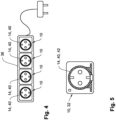
- the protective contact socket according to the invention is designed as a permanently installed socket, as a mobile cable coupling (multiple socket) or as an intermediate plug (adapter).
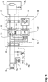
- Fig.1 shows a protective contact socket 10 according to the invention for insulation fault localization in an unearthed power supply system 2 (IT network), to which a consumer 6 is connected via active conductors L 1 , L 2 .
- IT network unearthed power supply system 2
- a standard insulation monitoring device 4 is connected between the active conductors L 1 , L 2 and earth PE, which superimposes a measuring voltage U m on the IT network.
- a measuring circuit is set up with a measuring current I m driven by the measuring voltage U m via the active conductors L 1 , L 2 , the insulation resistance R f and via the protective conductor (protective conductor connection with earth PE) back to the insulation monitoring device 4.
- the measuring current I m is measured in the insulation monitoring device 4 and allows a statement to be made about the size of the insulation resistance R f .
- the protective contact socket 10 comprises as essential elements a current measuring device 12, a signaling device 14 and a housing 16 with contacts 17.
- the contacts 17 are designed as plug contacts for connecting a plug of a supply line of the consumer 6.
- the measuring current transformer 20 detects the measuring current I m flowing in the measuring circuit, which continues as measuring differential current I dm in the active conductors L 1 and L 2 and transmits a differential current measurement result via a secondary winding 24 to the evaluation electronics 22.
Landscapes
- Physics & Mathematics (AREA)
- General Physics & Mathematics (AREA)
- Engineering & Computer Science (AREA)
- Microelectronics & Electronic Packaging (AREA)
- Optics & Photonics (AREA)
- Power Engineering (AREA)
- Testing Of Short-Circuits, Discontinuities, Leakage, Or Incorrect Line Connections (AREA)
- Measurement Of Resistance Or Impedance (AREA)
- Locating Faults (AREA)
Claims (11)
- Prise Schuko (10) pour la localisation d'un défaut d'isolement dans un système d'alimentation électrique (2) non mis à la terre incluant la surveillance d'isolement par un dispositif de surveillance d'isolement (4) standardisé qui superpose une tension de mesure (Um) au système d'alimentation électrique (2) non mis à la terre pour la détermination d'une résistance d'isolement (Rf) du système d'alimentation électrique (2) non mis à la terre,la prise Schuko (10) comprenantun boîtier (16) ayant des contacts électriques (17),un dispositif de signalisation (14) pour la signalisation d'un état d'isolement, etun dispositif de mesure de courant (12) pour la détection et pour l'évaluation d'un courant différentiel résiduel (Id, Idm, Idf), le dispositif de mesure de courant (12) ayant un transformateur de courant pour mesures (20) et un dispositif de détection électronique (22),caractérisée en ce quele dispositif de mesure de courant (12) est configuré pour la détection et l'évaluation à haute résolution d'un courant de mesure (Im) actionné par la tension de mesure (Um) comme courant différentiel résiduel de mesure (Id, Idm) et pour la détection et pour l'évaluation d'un courant de défaut (If) s'écoulant à une fréquence de réseau du système d'alimentation électrique (2) non mis à la terre comme courant différentiel résiduel de défaut (Id, Idf).
- Prise Schuko (10) pour la localisation d'un défaut d'isolement selon la revendication 1,
caractérisée en ce que
le dispositif de mesure de courant (12) est sensible à tous courants. - Prise Schuko (10) pour la localisation d'un défaut d'isolement selon la revendication 1 ou la revendication 2,
caractérisée en ce que
le dispositif de mesure de courant (12) a une boucle d'essai (15) acheminée par le transformateur de courant pour mesures (20) pour la génération d'un courant d'essai (It). - Prise Schuko (10) pour la localisation d'un défaut d'isolement selon l'une quelconque des revendications 1 à 3,
caractérisée en ce que
le dispositif de détection électronique (22) est configuré pour l'estimation de la courbe de courant différentiel résiduel pour mesures (Idm) afin d'établir une signalisation synchrone de défaut d'isolement entre le dispositif de surveillance d'isolement (4) et le dispositif pour la localisation d'un défaut d'isolement (10). - Prise Schuko (10) for localisation d'un défaut d'isolement selon l'une quelconque des revendications 1 à 4,
caractérisée par la réalisation comme fiche (32) installée de manière fixe, comme fiche intermédiaire (34) ou comme coupleur de ligne (36) mobile. - Procédé pour la localisation d'un défaut d'isolement dans un système d'alimentation électrique (2) non mis à la terre incluant la surveillance d'isolement par un dispositif de surveillance d'isolement (4) standardisé qui superpose une tension de mesure (Um) au système d'alimentation électrique (2) non mis à la terre pour la détermination d'une résistance d'isolement (Rf) du système d'alimentation électrique (2) non mis à la terre, le procédé comprenant les étapes de procédé à être effectuées dans une prise Schuko selon l'une quelconque des revendications 1 à 6 dans la présente invention :la détection et l'évaluation d'un courant différentiel résiduel (Id, Idm, Idf) au moyen d'un dispositif de mesure de courant (12) ayant un transformateur de courant pour mesures (20) et un dispositif de détection électronique (22),la signalisation d'un état d'isolement au moyen d'un dispositif de signalisation (14),un courant de mesure (Im) actionné par la tension de mesure (Um) étant détecté et évalué à haute résolution comme courant différentiel résiduel de mesure (Id, Idm) au moyen du dispositif de mesure de courant (12) et un courant de défaut (If) s'écoulant à une fréquence de réseau du système d'alimentation électrique (2) non mis à la terre étant détecté et évalué comme courant différentiel résiduel de défaut (Id, Idf) au moyen du dispositif de mesure de courant (12).
- Procédé pour la localisation d'un défaut d'isolement selon la revendication 6,
caractérisé en ce que
la détection et l'évaluation au moyen du dispositif de mesure de courant (12) sont sensibles à tous courants. - Procédé pour la localisation d'un défaut d'isolement selon la revendication 6 ou la revendication 7,
caractérisé par l'étape de
la génération d'un courant d'essai (It) qui est acheminé par le transformateur de courant pour mesures (20) du dispositif de mesure de courant (12) au moyen d'une boucle d'essai (15). - Procédé pour la localisation d'un défaut d'isolement selon l'une quelconque des revendications 6 à 8,
caractérisé par l'étape de
l'estimation de la courbe de courant différentiel résiduel pour mesures (Idm) au moyen du dispositif de détection électronique afin de synchroniser la signalisation de défaut d'isolement entre le dispositif de surveillance d'isolement (4) et le dispositif pour la localisation d'un défaut d'isolement (10). - Procédé pour la localisation d'un défaut d'isolement selon la revendication 9,
caractérisé en ce que
le courant différentiel résiduel de mesure (Idm) est estimé par la détection d'un change d'amplitude du courant différentiel résiduel de mesure (Idm). - Procédé pour la localisation d'un défaut d'isolement selon la revendication 9 ou la revendication 10,
caractérisé en ce que
la courbe de courant différentiel résiduel pour mesures (Idm) est estimée par la détection d'un change de modèle (M1, M2) du courant différentiel résiduel de mesure (Idm).
Applications Claiming Priority (1)
| Application Number | Priority Date | Filing Date | Title |
|---|---|---|---|
| DE102020114906.9A DE102020114906B4 (de) | 2020-06-04 | 2020-06-04 | Schutzkontaktsteckdose und Verfahren zur Isolationsfehlerlokalisierung in einem ungeerdeten Stromversorgungssystem mit Isolationsüberwachung |
Publications (2)
| Publication Number | Publication Date |
|---|---|
| EP3923010A1 EP3923010A1 (fr) | 2021-12-15 |
| EP3923010B1 true EP3923010B1 (fr) | 2024-07-03 |
Family
ID=76197293
Family Applications (1)
| Application Number | Title | Priority Date | Filing Date |
|---|---|---|---|
| EP21176785.0A Active EP3923010B1 (fr) | 2020-06-04 | 2021-05-31 | Prise de courant de sécurité et procédé de localisation des défauts d'isolation dans un système d'alimentation électrique non mis à la masse avec surveillance d'isolation |
Country Status (5)
| Country | Link |
|---|---|
| US (1) | US11789060B2 (fr) |
| EP (1) | EP3923010B1 (fr) |
| CN (1) | CN113834956B (fr) |
| DE (1) | DE102020114906B4 (fr) |
| MY (1) | MY207667A (fr) |
Families Citing this family (8)
| Publication number | Priority date | Publication date | Assignee | Title |
|---|---|---|---|---|
| DE102021131702B4 (de) * | 2021-12-01 | 2023-06-07 | Esa Elektroschaltanlagen Grimma Gmbh | Verfahren und Einrichtung zur Isolationsüberwachung und Isolationsfehlersuche für ungeerdete Stromversorgungsnetze |
| DE102022106394B3 (de) | 2022-03-18 | 2023-08-17 | Bender Gmbh & Co. Kg | Verfahren und Überwachungseinrichtung zur Bestimmung einesTeil-Isolationswiderstands und einer Teil-Netzableitkapazität in einem verzweigten ungeerdeten Stromversorgungssystem |
| KR20250002296A (ko) * | 2022-04-15 | 2025-01-07 | 디알에스 네이벌 파워 시스템즈, 인크. | 분산형 접지 검출을 위한 방법 및 시스템 |
| EP4407022A1 (fr) * | 2023-01-26 | 2024-07-31 | Sartorius Stedim Biotech GmbH | Système de bioprocédé pour une opération de bioprocédé avec un dispositif d'affichage pour afficher des informations de système concernant le système de bioprocédé |
| DE102023116532B3 (de) * | 2023-06-23 | 2024-10-02 | Bender Gmbh & Co. Kg | Verfahren und elektrische Schaltungsanordnung zur selektiven Isolationsüberwachung in einem Stromversorgungssystem mit abtrennbaren Subsystemen |
| CN119806299A (zh) * | 2023-10-09 | 2025-04-11 | 戴尔产品有限公司 | 检测电源单元中的短路 |
| DE102023136029B3 (de) * | 2023-12-20 | 2025-05-08 | Bender Gmbh & Co. Kg | Messanordnung und Messverfahren zur Messung einer Schleifenimpedanz in einem ungeerdeten Stromversorgungssystem |
| EP4644917A1 (fr) * | 2024-04-29 | 2025-11-05 | Safetytest GmbH | Dispositif de connexion électrique d'un consommateur électrique à une installation électrique |
Family Cites Families (20)
| Publication number | Priority date | Publication date | Assignee | Title |
|---|---|---|---|---|
| US6782329B2 (en) * | 1998-02-19 | 2004-08-24 | Square D Company | Detection of arcing faults using bifurcated wiring system |
| US6169406B1 (en) * | 1998-05-02 | 2001-01-02 | Stanley G. Peschel | Very low frequency high voltage sinusoidal electrical testing method, systems and apparatus |
| US20050218906A1 (en) * | 2004-03-31 | 2005-10-06 | Younsi Abdelkrim K | System and method for monitoring of insulation condition |
| DE202004006164U1 (de) | 2004-04-19 | 2004-08-19 | Ean Elektroschaltanlagen Grimma Gmbh | Einrichtung zur Isolationsfehlerortung in einem isolierten ungeerdeten Wechselstromnetz |
| DE202004008334U1 (de) | 2004-05-25 | 2004-09-02 | Geb, Nikolaus | BGVAZ-Steckdosenleiste |
| DE202005018741U1 (de) * | 2005-11-14 | 2006-03-02 | Ean Elektroschaltanlagen Gmbh | Einrichtung zur Ortung von Isolationsfehlern in isolierten ungeerdeten Wechselspannungsnetzen |
| CN102175957A (zh) * | 2011-02-17 | 2011-09-07 | 上海龙源智光电力技术有限公司 | 绝缘在线监测系统 |
| DE102011083792A1 (de) * | 2011-09-29 | 2013-04-04 | Bender Gmbh & Co. Kg | Isolationsfehlersuchgerät und Vorrichtung zur Isolationsfehlerlokalisierung in einem ungeerdeten Stromversorgungsnetz |
| GB201120295D0 (en) * | 2011-11-24 | 2012-01-04 | Metroic Ltd | Current measurement apparatus |
| CN104101812B (zh) * | 2013-04-09 | 2017-02-22 | 北京映翰通网络技术股份有限公司 | 一种小电流接地配电网单相接地故障检测定位方法与系统 |
| WO2015078753A1 (fr) * | 2013-11-27 | 2015-06-04 | Koninklijke Philips N.V. | Dispositif de détection permettant de détecter des photons et son procédé |
| DE102013225946B4 (de) * | 2013-12-13 | 2024-01-25 | Bender Gmbh & Co. Kg | Vorrichtung und Verfahren zur Isolationsüberwachung in einem Stromversorgungssystem mit hochohmig geerdetem Sternpunkt |
| DE102014201044B3 (de) | 2014-01-21 | 2015-03-05 | Bender Gmbh & Co. Kg | Isolationsüberwachungsvorrichtung zur simultanen Überwachung von Netzabschnitten eines ungeerdeten Stromversorgungssystems |
| TWI539169B (zh) * | 2014-04-08 | 2016-06-21 | Univ Kao Yuan | High Sensitivity Non - grounded DC Power Supply Insulation Resistance Detection Method and Its Circuit |
| DE102014223287A1 (de) | 2014-11-14 | 2016-05-19 | Bender Gmbh & Co. Kg | Elektrische Schutzeinrichtung und Verfahren zur selektiven Abschaltung eines Subsystems bei einem zweiten Fehler in einem IT-Stromversorgungssystem |
| FR3037406B1 (fr) * | 2015-06-15 | 2017-06-02 | Renault Sas | Systeme electrique comportant un circuit de detection d’un defaut d’isolement electrique |
| DE102017209663B3 (de) * | 2017-06-08 | 2018-10-18 | Bender Gmbh & Co. Kg | Verfahren zur Isolationsfehlersuche und Isolationsfehlersucheinrichtung für ein ungeerdetes Stromversorgungssystem |
| EP3477808B1 (fr) | 2017-10-24 | 2023-08-16 | Siemens Aktiengesellschaft | Procédé, appareil de protection et système de protection permettant de reconnaître un défaut sur une ligne d'un réseau d'alimentation électrique |
| JP6930370B2 (ja) * | 2017-10-30 | 2021-09-01 | オムロン株式会社 | 地絡検出装置 |
| HUP1700439A1 (hu) * | 2017-10-31 | 2019-05-28 | Jozsef Bela Prause | Eljárás és készülék egyenáramú hálózatok szigetelési ellenállásának meghatározására, valamint akkumulátoros rendszerek potenciál-csökkentésére vagy emelésére, funkcionális földeléssel |
-
2020
- 2020-06-04 DE DE102020114906.9A patent/DE102020114906B4/de active Active
-
2021
- 2021-05-31 EP EP21176785.0A patent/EP3923010B1/fr active Active
- 2021-06-03 MY MYPI2021003091A patent/MY207667A/en unknown
- 2021-06-04 US US17/338,770 patent/US11789060B2/en active Active
- 2021-06-04 CN CN202110626695.4A patent/CN113834956B/zh active Active
Also Published As
| Publication number | Publication date |
|---|---|
| US11789060B2 (en) | 2023-10-17 |
| US20210382104A1 (en) | 2021-12-09 |
| DE102020114906A1 (de) | 2021-12-09 |
| MY207667A (en) | 2025-03-11 |
| CN113834956A (zh) | 2021-12-24 |
| EP3923010A1 (fr) | 2021-12-15 |
| CN113834956B (zh) | 2024-09-17 |
| DE102020114906B4 (de) | 2023-06-29 |
Similar Documents
| Publication | Publication Date | Title |
|---|---|---|
| DE102020114906B4 (de) | Schutzkontaktsteckdose und Verfahren zur Isolationsfehlerlokalisierung in einem ungeerdeten Stromversorgungssystem mit Isolationsüberwachung | |
| EP2574939B1 (fr) | Appareil de détection de défauts d'isolation et dispositif de localisation de défauts d'isolation dans un réseau d'alimentation de courant non mis à la terre | |
| DE102011076320B4 (de) | Erdungsüberwachungs-Vorrichtung und Ladesystem | |
| EP3139188B1 (fr) | Procédé et dispositif de recherche d'erreur d'isolation comprenant une détermination adaptative de courant de test | |
| EP3524985A1 (fr) | Dispositif et procédé pour une surveillance de l'isolation à reconnaissance d'un conducteur extérieur défectueux dans un système d'alimentation électrique non mis à la masse triphasé | |
| DE102014223287A1 (de) | Elektrische Schutzeinrichtung und Verfahren zur selektiven Abschaltung eines Subsystems bei einem zweiten Fehler in einem IT-Stromversorgungssystem | |
| DE102013207775B4 (de) | Vorrichtung zum Erkennen einer Störung einer elektrischen Leitung | |
| DE102016200309B3 (de) | Verfahren zum Erkennen einer Unterbrechung eines aktiven Leiters in einem ungeerdeten Gleichspannungs-Stromversorgungssystem | |
| WO2020207729A1 (fr) | Détection d'un défaut à la terre dans un réseau à tension continue | |
| AT511991B1 (de) | Verfahren und einrichtung zum versorgen wenigstens eines elektrischen verbrauchers eines bohrgestänges mit einer betriebsspannung | |
| EP4099029A1 (fr) | Dispositif de circuit électrique destiné à la surveillance d'isolement conforme aux normes, à arrêt rapide lors de la détection du raccordement à la terre pour un système d'alimentation électrique non mis à la terre | |
| EP1197936B2 (fr) | Système d'alarme | |
| EP4484967B1 (fr) | Dispositif de test de tension capacitif | |
| DE102021124432B4 (de) | Erdschlussdetektionsgerät zum Detektieren eines erdfühligen Fehlers in einem Niederspannungskabelnetz | |
| DE102022106394B3 (de) | Verfahren und Überwachungseinrichtung zur Bestimmung einesTeil-Isolationswiderstands und einer Teil-Netzableitkapazität in einem verzweigten ungeerdeten Stromversorgungssystem | |
| DE102012100193B4 (de) | Photovoltaikanordnung, die eine Solaranlage und einen Solarwechselrichter umfasst, und Verfahren zum Betrieb einer solchen Photovoltaikanordnung | |
| EP4575525B1 (fr) | Dispositif de mesure et procédé de mesure pour mesurer une impédance de broyage dans un système d'alimentation électrique non mis à la terre | |
| DE102010013103B4 (de) | Vorrichtung und Verfahren zur Diagnose von Messobjekten unter Verwendung einer Messspannung | |
| DE19515068A1 (de) | Anordnung zur TE-Detektion in Hochspannungskabeln und in deren Verbindungselementen | |
| DE102023129474B4 (de) | In situ-Überwachung von dynamisch-mechanisch gestressten Versorgungs- und/oder Steuerleitungen | |
| EP2612155B1 (fr) | Dispositif et procédé de localisation d'un défaut à la terre dans un câble | |
| DE102009061072B4 (de) | Selbstüberwachende Anschlussleitung und Betriebsmittel | |
| DE102006021859B4 (de) | Steckverbinder mit Zuleitung | |
| EP4733791A1 (fr) | Procédés et dispositifs de contrôle et de surveillance de la continuité d'une ligne pen pour un système d'alimentation triphasée en courant tn-c | |
| EP4644917A1 (fr) | Dispositif de connexion électrique d'un consommateur électrique à une installation électrique |
Legal Events
| Date | Code | Title | Description |
|---|---|---|---|
| PUAI | Public reference made under article 153(3) epc to a published international application that has entered the european phase |
Free format text: ORIGINAL CODE: 0009012 |
|
| STAA | Information on the status of an ep patent application or granted ep patent |
Free format text: STATUS: THE APPLICATION HAS BEEN PUBLISHED |
|
| AK | Designated contracting states |
Kind code of ref document: A1 Designated state(s): AL AT BE BG CH CY CZ DE DK EE ES FI FR GB GR HR HU IE IS IT LI LT LU LV MC MK MT NL NO PL PT RO RS SE SI SK SM TR |
|
| B565 | Issuance of search results under rule 164(2) epc |
Effective date: 20211111 |
|
| STAA | Information on the status of an ep patent application or granted ep patent |
Free format text: STATUS: REQUEST FOR EXAMINATION WAS MADE |
|
| 17P | Request for examination filed |
Effective date: 20220530 |
|
| RBV | Designated contracting states (corrected) |
Designated state(s): AL AT BE BG CH CY CZ DE DK EE ES FI FR GB GR HR HU IE IS IT LI LT LU LV MC MK MT NL NO PL PT RO RS SE SI SK SM TR |
|
| RIC1 | Information provided on ipc code assigned before grant |
Ipc: G01R 31/52 20200101AFI20231207BHEP |
|
| GRAP | Despatch of communication of intention to grant a patent |
Free format text: ORIGINAL CODE: EPIDOSNIGR1 |
|
| STAA | Information on the status of an ep patent application or granted ep patent |
Free format text: STATUS: GRANT OF PATENT IS INTENDED |
|
| INTG | Intention to grant announced |
Effective date: 20240118 |
|
| GRAS | Grant fee paid |
Free format text: ORIGINAL CODE: EPIDOSNIGR3 |
|
| GRAA | (expected) grant |
Free format text: ORIGINAL CODE: 0009210 |
|
| STAA | Information on the status of an ep patent application or granted ep patent |
Free format text: STATUS: THE PATENT HAS BEEN GRANTED |
|
| AK | Designated contracting states |
Kind code of ref document: B1 Designated state(s): AL AT BE BG CH CY CZ DE DK EE ES FI FR GB GR HR HU IE IS IT LI LT LU LV MC MK MT NL NO PL PT RO RS SE SI SK SM TR |
|
| REG | Reference to a national code |
Ref country code: CH Ref legal event code: EP |
|
| REG | Reference to a national code |
Ref country code: DE Ref legal event code: R096 Ref document number: 502021004190 Country of ref document: DE |
|
| P01 | Opt-out of the competence of the unified patent court (upc) registered |
Free format text: CASE NUMBER: APP_40118/2024 Effective date: 20240705 |
|
| REG | Reference to a national code |
Ref country code: LT Ref legal event code: MG9D |
|
| REG | Reference to a national code |
Ref country code: NL Ref legal event code: MP Effective date: 20240703 |
|
| PG25 | Lapsed in a contracting state [announced via postgrant information from national office to epo] |
Ref country code: PT Free format text: LAPSE BECAUSE OF FAILURE TO SUBMIT A TRANSLATION OF THE DESCRIPTION OR TO PAY THE FEE WITHIN THE PRESCRIBED TIME-LIMIT Effective date: 20241104 |
|
| PG25 | Lapsed in a contracting state [announced via postgrant information from national office to epo] |
Ref country code: NL Free format text: LAPSE BECAUSE OF FAILURE TO SUBMIT A TRANSLATION OF THE DESCRIPTION OR TO PAY THE FEE WITHIN THE PRESCRIBED TIME-LIMIT Effective date: 20240703 |
|
| PG25 | Lapsed in a contracting state [announced via postgrant information from national office to epo] |
Ref country code: PT Free format text: LAPSE BECAUSE OF FAILURE TO SUBMIT A TRANSLATION OF THE DESCRIPTION OR TO PAY THE FEE WITHIN THE PRESCRIBED TIME-LIMIT Effective date: 20241104 Ref country code: NL Free format text: LAPSE BECAUSE OF FAILURE TO SUBMIT A TRANSLATION OF THE DESCRIPTION OR TO PAY THE FEE WITHIN THE PRESCRIBED TIME-LIMIT Effective date: 20240703 |
|
| PG25 | Lapsed in a contracting state [announced via postgrant information from national office to epo] |
Ref country code: NO Free format text: LAPSE BECAUSE OF FAILURE TO SUBMIT A TRANSLATION OF THE DESCRIPTION OR TO PAY THE FEE WITHIN THE PRESCRIBED TIME-LIMIT Effective date: 20241003 |
|
| PG25 | Lapsed in a contracting state [announced via postgrant information from national office to epo] |
Ref country code: FI Free format text: LAPSE BECAUSE OF FAILURE TO SUBMIT A TRANSLATION OF THE DESCRIPTION OR TO PAY THE FEE WITHIN THE PRESCRIBED TIME-LIMIT Effective date: 20240703 Ref country code: GR Free format text: LAPSE BECAUSE OF FAILURE TO SUBMIT A TRANSLATION OF THE DESCRIPTION OR TO PAY THE FEE WITHIN THE PRESCRIBED TIME-LIMIT Effective date: 20241004 Ref country code: PL Free format text: LAPSE BECAUSE OF FAILURE TO SUBMIT A TRANSLATION OF THE DESCRIPTION OR TO PAY THE FEE WITHIN THE PRESCRIBED TIME-LIMIT Effective date: 20240703 |
|
| PG25 | Lapsed in a contracting state [announced via postgrant information from national office to epo] |
Ref country code: BG Free format text: LAPSE BECAUSE OF FAILURE TO SUBMIT A TRANSLATION OF THE DESCRIPTION OR TO PAY THE FEE WITHIN THE PRESCRIBED TIME-LIMIT Effective date: 20240703 |
|
| PG25 | Lapsed in a contracting state [announced via postgrant information from national office to epo] |
Ref country code: LV Free format text: LAPSE BECAUSE OF FAILURE TO SUBMIT A TRANSLATION OF THE DESCRIPTION OR TO PAY THE FEE WITHIN THE PRESCRIBED TIME-LIMIT Effective date: 20240703 |
|
| PG25 | Lapsed in a contracting state [announced via postgrant information from national office to epo] |
Ref country code: IS Free format text: LAPSE BECAUSE OF FAILURE TO SUBMIT A TRANSLATION OF THE DESCRIPTION OR TO PAY THE FEE WITHIN THE PRESCRIBED TIME-LIMIT Effective date: 20241103 |
|
| PG25 | Lapsed in a contracting state [announced via postgrant information from national office to epo] |
Ref country code: HR Free format text: LAPSE BECAUSE OF FAILURE TO SUBMIT A TRANSLATION OF THE DESCRIPTION OR TO PAY THE FEE WITHIN THE PRESCRIBED TIME-LIMIT Effective date: 20240703 Ref country code: CZ Free format text: LAPSE BECAUSE OF FAILURE TO SUBMIT A TRANSLATION OF THE DESCRIPTION OR TO PAY THE FEE WITHIN THE PRESCRIBED TIME-LIMIT Effective date: 20240703 |
|
| PG25 | Lapsed in a contracting state [announced via postgrant information from national office to epo] |
Ref country code: ES Free format text: LAPSE BECAUSE OF FAILURE TO SUBMIT A TRANSLATION OF THE DESCRIPTION OR TO PAY THE FEE WITHIN THE PRESCRIBED TIME-LIMIT Effective date: 20240703 Ref country code: RS Free format text: LAPSE BECAUSE OF FAILURE TO SUBMIT A TRANSLATION OF THE DESCRIPTION OR TO PAY THE FEE WITHIN THE PRESCRIBED TIME-LIMIT Effective date: 20241003 |
|
| PG25 | Lapsed in a contracting state [announced via postgrant information from national office to epo] |
Ref country code: RS Free format text: LAPSE BECAUSE OF FAILURE TO SUBMIT A TRANSLATION OF THE DESCRIPTION OR TO PAY THE FEE WITHIN THE PRESCRIBED TIME-LIMIT Effective date: 20241003 Ref country code: PL Free format text: LAPSE BECAUSE OF FAILURE TO SUBMIT A TRANSLATION OF THE DESCRIPTION OR TO PAY THE FEE WITHIN THE PRESCRIBED TIME-LIMIT Effective date: 20240703 Ref country code: NO Free format text: LAPSE BECAUSE OF FAILURE TO SUBMIT A TRANSLATION OF THE DESCRIPTION OR TO PAY THE FEE WITHIN THE PRESCRIBED TIME-LIMIT Effective date: 20241003 Ref country code: LV Free format text: LAPSE BECAUSE OF FAILURE TO SUBMIT A TRANSLATION OF THE DESCRIPTION OR TO PAY THE FEE WITHIN THE PRESCRIBED TIME-LIMIT Effective date: 20240703 Ref country code: IS Free format text: LAPSE BECAUSE OF FAILURE TO SUBMIT A TRANSLATION OF THE DESCRIPTION OR TO PAY THE FEE WITHIN THE PRESCRIBED TIME-LIMIT Effective date: 20241103 Ref country code: HR Free format text: LAPSE BECAUSE OF FAILURE TO SUBMIT A TRANSLATION OF THE DESCRIPTION OR TO PAY THE FEE WITHIN THE PRESCRIBED TIME-LIMIT Effective date: 20240703 Ref country code: GR Free format text: LAPSE BECAUSE OF FAILURE TO SUBMIT A TRANSLATION OF THE DESCRIPTION OR TO PAY THE FEE WITHIN THE PRESCRIBED TIME-LIMIT Effective date: 20241004 Ref country code: FI Free format text: LAPSE BECAUSE OF FAILURE TO SUBMIT A TRANSLATION OF THE DESCRIPTION OR TO PAY THE FEE WITHIN THE PRESCRIBED TIME-LIMIT Effective date: 20240703 Ref country code: ES Free format text: LAPSE BECAUSE OF FAILURE TO SUBMIT A TRANSLATION OF THE DESCRIPTION OR TO PAY THE FEE WITHIN THE PRESCRIBED TIME-LIMIT Effective date: 20240703 Ref country code: CZ Free format text: LAPSE BECAUSE OF FAILURE TO SUBMIT A TRANSLATION OF THE DESCRIPTION OR TO PAY THE FEE WITHIN THE PRESCRIBED TIME-LIMIT Effective date: 20240703 Ref country code: BG Free format text: LAPSE BECAUSE OF FAILURE TO SUBMIT A TRANSLATION OF THE DESCRIPTION OR TO PAY THE FEE WITHIN THE PRESCRIBED TIME-LIMIT Effective date: 20240703 |
|
| REG | Reference to a national code |
Ref country code: DE Ref legal event code: R097 Ref document number: 502021004190 Country of ref document: DE |
|
| PG25 | Lapsed in a contracting state [announced via postgrant information from national office to epo] |
Ref country code: RO Free format text: LAPSE BECAUSE OF FAILURE TO SUBMIT A TRANSLATION OF THE DESCRIPTION OR TO PAY THE FEE WITHIN THE PRESCRIBED TIME-LIMIT Effective date: 20240703 Ref country code: DK Free format text: LAPSE BECAUSE OF FAILURE TO SUBMIT A TRANSLATION OF THE DESCRIPTION OR TO PAY THE FEE WITHIN THE PRESCRIBED TIME-LIMIT Effective date: 20240703 Ref country code: SM Free format text: LAPSE BECAUSE OF FAILURE TO SUBMIT A TRANSLATION OF THE DESCRIPTION OR TO PAY THE FEE WITHIN THE PRESCRIBED TIME-LIMIT Effective date: 20240703 |
|
| PG25 | Lapsed in a contracting state [announced via postgrant information from national office to epo] |
Ref country code: EE Free format text: LAPSE BECAUSE OF FAILURE TO SUBMIT A TRANSLATION OF THE DESCRIPTION OR TO PAY THE FEE WITHIN THE PRESCRIBED TIME-LIMIT Effective date: 20240703 |
|
| PG25 | Lapsed in a contracting state [announced via postgrant information from national office to epo] |
Ref country code: IT Free format text: LAPSE BECAUSE OF FAILURE TO SUBMIT A TRANSLATION OF THE DESCRIPTION OR TO PAY THE FEE WITHIN THE PRESCRIBED TIME-LIMIT Effective date: 20240703 Ref country code: SK Free format text: LAPSE BECAUSE OF FAILURE TO SUBMIT A TRANSLATION OF THE DESCRIPTION OR TO PAY THE FEE WITHIN THE PRESCRIBED TIME-LIMIT Effective date: 20240703 |
|
| PLBE | No opposition filed within time limit |
Free format text: ORIGINAL CODE: 0009261 |
|
| STAA | Information on the status of an ep patent application or granted ep patent |
Free format text: STATUS: NO OPPOSITION FILED WITHIN TIME LIMIT |
|
| 26N | No opposition filed |
Effective date: 20250404 |
|
| PGFP | Annual fee paid to national office [announced via postgrant information from national office to epo] |
Ref country code: DE Payment date: 20250519 Year of fee payment: 5 |
|
| PGFP | Annual fee paid to national office [announced via postgrant information from national office to epo] |
Ref country code: GB Payment date: 20250522 Year of fee payment: 5 |
|
| PGFP | Annual fee paid to national office [announced via postgrant information from national office to epo] |
Ref country code: FR Payment date: 20250521 Year of fee payment: 5 |
|
| PG25 | Lapsed in a contracting state [announced via postgrant information from national office to epo] |
Ref country code: SE Free format text: LAPSE BECAUSE OF FAILURE TO SUBMIT A TRANSLATION OF THE DESCRIPTION OR TO PAY THE FEE WITHIN THE PRESCRIBED TIME-LIMIT Effective date: 20240703 |
|
| REG | Reference to a national code |
Ref country code: CH Ref legal event code: H13 Free format text: ST27 STATUS EVENT CODE: U-0-0-H10-H13 (AS PROVIDED BY THE NATIONAL OFFICE) Effective date: 20251223 |
|
| PG25 | Lapsed in a contracting state [announced via postgrant information from national office to epo] |
Ref country code: LU Free format text: LAPSE BECAUSE OF NON-PAYMENT OF DUE FEES Effective date: 20250531 |
|
| PG25 | Lapsed in a contracting state [announced via postgrant information from national office to epo] |
Ref country code: CH Free format text: LAPSE BECAUSE OF NON-PAYMENT OF DUE FEES Effective date: 20250531 |
|
| REG | Reference to a national code |
Ref country code: BE Ref legal event code: MM Effective date: 20250531 |
|
| PG25 | Lapsed in a contracting state [announced via postgrant information from national office to epo] |
Ref country code: MC Free format text: LAPSE BECAUSE OF FAILURE TO SUBMIT A TRANSLATION OF THE DESCRIPTION OR TO PAY THE FEE WITHIN THE PRESCRIBED TIME-LIMIT Effective date: 20240703 |
|
| PG25 | Lapsed in a contracting state [announced via postgrant information from national office to epo] |
Ref country code: IE Free format text: LAPSE BECAUSE OF NON-PAYMENT OF DUE FEES Effective date: 20250531 |
|
| PGFP | Annual fee paid to national office [announced via postgrant information from national office to epo] |
Ref country code: AT Payment date: 20260410 Year of fee payment: 5 |
|
| PG25 | Lapsed in a contracting state [announced via postgrant information from national office to epo] |
Ref country code: BE Free format text: LAPSE BECAUSE OF NON-PAYMENT OF DUE FEES Effective date: 20250531 |