EP3923053B1 - Câble à nervure et rainuré ayant un élément de résistance incorporé avec un revêtement bloquant l'eau - Google Patents
Câble à nervure et rainuré ayant un élément de résistance incorporé avec un revêtement bloquant l'eau Download PDFInfo
- Publication number
- EP3923053B1 EP3923053B1 EP21179369.0A EP21179369A EP3923053B1 EP 3923053 B1 EP3923053 B1 EP 3923053B1 EP 21179369 A EP21179369 A EP 21179369A EP 3923053 B1 EP3923053 B1 EP 3923053B1
- Authority
- EP
- European Patent Office
- Prior art keywords
- ribs
- optical fiber
- ribbed
- fiber cable
- sheath
- Prior art date
- Legal status (The legal status is an assumption and is not a legal conclusion. Google has not performed a legal analysis and makes no representation as to the accuracy of the status listed.)
- Active
Links
Images




Classifications
-
- G—PHYSICS
- G02—OPTICS
- G02B—OPTICAL ELEMENTS, SYSTEMS OR APPARATUS
- G02B6/00—Light guides; Structural details of arrangements comprising light guides and other optical elements, e.g. couplings
- G02B6/44—Mechanical structures for providing tensile strength and external protection for fibres, e.g. optical transmission cables
- G02B6/4401—Optical cables
- G02B6/4429—Means specially adapted for strengthening or protecting the cables
- G02B6/443—Protective covering
-
- G—PHYSICS
- G02—OPTICS
- G02B—OPTICAL ELEMENTS, SYSTEMS OR APPARATUS
- G02B6/00—Light guides; Structural details of arrangements comprising light guides and other optical elements, e.g. couplings
- G02B6/44—Mechanical structures for providing tensile strength and external protection for fibres, e.g. optical transmission cables
- G02B6/4401—Optical cables
- G02B6/4429—Means specially adapted for strengthening or protecting the cables
- G02B6/4435—Corrugated mantle
-
- G—PHYSICS
- G02—OPTICS
- G02B—OPTICAL ELEMENTS, SYSTEMS OR APPARATUS
- G02B6/00—Light guides; Structural details of arrangements comprising light guides and other optical elements, e.g. couplings
- G02B6/44—Mechanical structures for providing tensile strength and external protection for fibres, e.g. optical transmission cables
- G02B6/4401—Optical cables
- G02B6/4429—Means specially adapted for strengthening or protecting the cables
- G02B6/44384—Means specially adapted for strengthening or protecting the cables the means comprising water blocking or hydrophobic materials
Definitions
- Embodiments of the present disclosure relate to a field optical communication technology. And more particularly, relates to a ribbed and grooved optical cable.
- optical fiber communication technology using a variety of optical fiber cables.
- the optical fiber cables are widely used for communication to meet the increasing demands of end-users. To meet the increasing demands, installation of the optical fiber cables at a rapid pace becomes essential.
- the optical fiber cables for telecommunication application are installed in ducts.
- the installation of the optical fiber cables in the ducts is mostly performed using a blowing method, wherein, the blowing method to install the optical fiber cables in the ducts is dependent on a plurality of factors.
- the plurality of factors includes mass of the optical fiber cable, friction, stiffness, and the like.
- the blowing method enables installation of the optical fiber cable using pressurized air combined with additional mechanical pushing force that is called "blowing".
- the blowing method is the process of installation of the optical fiber cable into a pre-installed duct.
- the blowing is performed by injecting pressurized air inlet of the pre-installed duct before the optical fiber cable is pushed into the pre-installed duct.
- the pressurized air flows at high speed through the pre-installed duct and along the optical fiber cable.
- pushing force is applied near the optical fiber cable inlet by a pushing device.
- the optical fiber cable includes uni-tube, multi-tube, unarmoured, armoured, micro duct cable, and the like.
- conventional structure of optical fiber cable makes it inefficient to allow pressurized air to blow the optical fiber cable in the pre-installed duct.
- the conventional optical fiber cable resists the pushing force due to higher coefficient of friction.
- the conventional optical fiber cable has a higher number of contact points with the pre-installed duct.
- the conventional optical fiber cable has heavy weight.
- strength members are one of the important components of the optical fiber cable.
- the purpose of the strength members is to provide the optical fiber cable rigidity, bend resistance, mechanical strength and ease in blowing.
- a strength member can be installed either at a center of the optical fiber cable or embedded inside the sheath of the optical fiber cable.
- the strength member embedded inside the sheath is normally preferred over a central strength member for making a high density optical fiber cable as there is more space available in the center. After embedding the strength member in the sheath of the optical fiber cable, often water penetration occurs through the embedded strength member. The main reason is, during the embedding of the strength member inside the sheath, some clearance remains between the strength member and the sheath due to manufacturing tolerances.
- the water may penetrate even through a clearance of a few dozen microns.
- a water penetration test of the optical fiber cable is often carried out to assess the ability of the optical fiber cable to resist the water penetration in the optical fiber cable.
- Such water penetration assessments are necessary because water once penetrated through the clearance between the strength member and the sheath due to manufacturing tolerances, may travel to optical fiber junction boxes and may degrade optical properties of the components such as optical fibers.
- water penetration through a length of the optical fiber cable further leads to degradation of other components of the optical network.
- a prior-art reference “ WO2020075734A1” discloses an optical fiber cable having a plurality of ribs on the surface of the optical fiber cable for improved blowing performance, however the ribs are of the same height.
- Another prior art, JP-A-2000/019366 discloses optical fiber unit with respect to the application as to which diameter-narrowing and weight reduction of an optical fiber unit are requested/required.
- Another prior art, JP-A-2013/171220 discloses the optical fiber cable used for premises wiring such as a building/bill.
- JP-A-H0248608 discloses a light having a tensile strength line arranged in the center, a plurality of grooves for accommodating optical fibers provided on the outer periphery by a thermoplastic resin, and a spiral shape in which the grooves are alternately inverted.
- Another prior art, US-A1-2006/104579 discloses optical fiber cables having a central strength member encircled by a circumferentially continuous jacket or sheath which has therein at least one longitudinally extending chamber or duct which receives an optical fiber or optical fibers, the jacket being manually separable from the strength member.
- CN-U-202119952 discloses the stranded type air-blowing optical cable that declines that a kind of surface has concavo-convex groove.
- the present invention provides a ribbed and grooved cable having embedded strength members with water blocking coating according to claim 1.
- the ribbed grooved optical fiber cable includes a core with a plurality of optical fibers, a sheath enveloping the core and the sheath has an outer surface and an inner surface, the outer surface of the sheath has a plurality of external ribs and a plurality of external grooves and one or more strength members embedded in the sheath.
- the one or more strength members are coated with a water blocking coating material having at least one of an ultraviolet (UV) curable water swellable resin composition and a layer of ethylene acrylic acid (EAA).
- UV ultraviolet
- EAA ethylene acrylic acid
- the UV curable water swellable resin composition includes acrylic acid, phenyl bis(2,4,6-trimethylbenzoyl)-phosphine oxide and oxybis(methyl-2,1-ethanediyl) diacrylate.
- the UV curable water swellable resin composition is applied directly on the one or more strength members or above a thin layer of ethylene acrylic acid (EAA).
- EAA ethylene acrylic acid
- the UV curable water swellable resin composition coated one or more strength members are passed through one or more UV chambers to cure the UV curable water swellable resin composition.
- the water blocking coating material applied over the one or more strength members has a thickness of 50 ⁇ 10 microns.
- the one or more strength members are made of a fiber reinforced plastic (FRP), an aramid reinforced plastic (ARP) or alike material.
- the plurality of external ribs are arranged alternately throughout the outer surface of the sheath of the ribbed grooved optical fiber cable.
- the plurality of external ribs having the first height and the second height are arranged in such a way that the plurality of external ribs having the first height and the plurality of external ribs having the second height are positioned diagonally opposite to each other.
- the plurality of external ribs of the sheath have at least two heights including a first height and a second height.
- the first height is in a range of 0.2 millimeters to 1.0 millimeters and the second height is in the range of 0.1 millimeters to 0.5 millimeters.
- the plurality of external ribs and the plurality of external grooves has a width in the range of 1.2 millimeters to 2.5 millimeters.
- the shape of the plurality of external ribs and the plurality of external grooves is any rectangular shape with rounded edges, a pointy triangle shape, a circular shape, a curve-type shape or any suitable shape.
- the sheath and the plurality of external ribs are made of a same material.
- the sheath and the plurality of external ribs are made of different materials.
- the ribbed grooved optical fiber cable has a diameter in the range of 11 to 13 millimeters and has a blowing of more than 1100 meters in a duct with an inner diameter of 14 millimeters and an outer diameter of 18 millimeters.
- the plurality of internal ribs and the plurality of internal grooves are arranged alternately throughout the inner surface of the sheath.
- the plurality of internal grooves is made to reduce weight of the ribbed grooved optical fiber cable.
- a shape of the plurality of internal ribs and the plurality of internal grooves has a rectangular shape with rounded edges, a pointy triangle shape, a circular shape, a curve-type shape or alike shape.
- the plurality of internal ribs has a height in a range of 0.1 millimeter to 1.0 millimeter.
- the plurality of internal ribs and the plurality of internal grooves has a width in the range of 1.2 millimeter to 2.5 millimeters.
- the sheath used in the ribbed grooved optical fiber cable passes a water penetration test at 0.1 bar pressure water-head applied to a 3 meter optical cable for at least 24 hours.
- Fig. 1 illustrates a design of a sheath of an optical ribbed and grooved 100 having a plurality of ribs and a plurality of grooves on an external surface of the sheath and strength members embedded inside the sheath in accordance with the first configuration which lies outside the scope of the present invention.
- the cable is termed as a ribbed and grooved optical fiber cable 100 as it has a ribbed and grooved sheath.
- the ribbed and grooved optical fiber cable 100 includes a plurality of optical fibers (not shown) and the sheath 102 having a plurality of ribs 104 and a plurality of grooves 106.
- the sheath 102 has a plurality of strength members 108 embedded into it.
- the sheath 102 includes an inner surface and an outer surface.
- sheath is an outer layer of a ribbed grooved optical fiber cable 100 protects the optical fiber cable from environmental conditions.
- the environment conditions include but may not be limited to rainfall, sunlight, snowfall, and wind.
- the sheath 102 of the ribbed and grooved optical fiber cable 100 encloses the plurality of optical fibers concentrically along a length of the optical fiber cable.
- the sheath has an outer surface and an inner surface.
- the outer surface of the sheath 102 of the ribbed and grooved optical fiber cable 100 includes the plurality of ribs 104 and the plurality of grooves 106.
- the plurality of ribs 104 and the plurality of grooves 106 are formed on the outer surface of the sheath 102, thus called as a plurality of external ribs and a plurality of external grooves throughout the description.
- the number of the plurality of ribs 104 is the same as the number of the plurality of grooves 106. In one embodiment, each of the plurality of ribs 104 has depth in range of about 0.1 millimeter to 2 millimeters. In another embodiment of the present disclosure, the plurality of ribs 104 has depth in range of about 0.2 millimeter to 1 millimeter.
- depth of the plurality of ribs 104 may vary.
- the plurality of ribs 104 has width in range of about 0.4 millimeter to 20 millimeter. In another embodiment, the plurality of ribs 104 has width in range of about 0.5 millimeter to 4 millimeter. In yet another embodiment, width of the plurality of ribs 104 may vary. In one aspect, the plurality of ribs 104 may be 12. In another aspect of the present disclosure, the plurality of ribs 104 may vary depending upon the width of the plurality of ribs 104. In an embodiment, the number of grooves 106 is 12. In another embodiment, the plurality of grooves 106 may vary depending upon width of the plurality of grooves 106.
- the area of the ribbed and grooved optical fiber cable 100 corresponding to 12 ribs and 12 grooves is about 44.45 millimeter square. In another aspect, the area of the cable may vary depending upon internal diameter of the cable, external diameter of the cable, number of the plurality of ribs 104 and the plurality of grooves 106.
- the ribbed and grooved optical fiber cable 100 has deformation of about 0.59 under crushing load at 500 Newton per 100 millimeter. In another aspect, the deformation of the ribbed and grooved optical fiber cable 100 may vary. In particular, deformation of the ribbed and grooved optical fiber cable 100 may vary depending upon a plurality of parameters.
- the plurality of parameters includes but may not be limited to number of the plurality of ribs 104 and the plurality of grooves 106, width and height of the plurality of ribs 104 and the plurality of grooves 106, inside and outside diameter of the ribbed and grooved optical fiber cable 100, number of the plurality of strength members 108 in the sheath 102, and material grade of the ribbed and grooved optical fiber cable 100.
- the plurality of ribs 104 and the plurality of grooves 106 reduce coefficient of friction between the sheath 102 and a duct.
- the plurality of ribs 104 and the plurality of grooves 106 are arranged alternately to each other on the outer surface of the sheath 102.
- a groove of the plurality of grooves 106 is present on both sides of each rib of the plurality of ribs 104.
- a rib of the plurality of ribs 104 is present on both sides of each groove of the plurality of grooves 106.
- the height of each of the plurality of ribs 104 is equal.
- height of each of the plurality of grooves 106 is equal.
- the ribbed and grooved optical fiber cable 100 is installed into the duct using a blowing process.
- the duct surrounds the ribbed and grooved optical fiber cable 100.
- the blowing process to install the ribbed and grooved optical fiber cable 100 in the duct is dependent on a plurality of factors.
- the plurality of factors includes mass of the ribbed and grooved optical fiber cable 100, friction between the ribbed and grooved optical fiber cable 100 and the duct, stiffness of the ribbed and grooved optical fiber cable 100, and the like.
- the blowing process enables installation of the ribbed and grooved optical fiber cable 100 using pressurized air combined with a mechanical pushing force.
- the ribbed and grooved optical fiber cable 100 includes the plurality of strength members 108. Furthermore, each of the plurality of strength members 108 is embedded in the sheath 102.
- each of the plurality of strength elements 108 in the sheath 102 may be positioned differently.
- the plurality of strength members 108 enhances blowing performance of the ribbed and grooved optical fiber cable 100 by increasing stiffness of the ribbed and grooved optical fiber cable 100.
- the plurality of strength members 108 provides tensile strength to the ribbed and grooved optical fiber cable 100.
- the plurality of strength members 108 embedded in the sheath 102 of the ribbed and grooved optical fiber cable 100 is in the range of 4 to 18. In another embodiment, the number of the plurality of strength members 108 may vary.
- Fig. 2 illustrates the sheath having the plurality of ribs and the plurality of grooves on the external surface of the sheath and strength members embedded inside the sheath in accordance with a second configuration which lies outside the scope of the present invention.
- the plurality of ribs 104 in the sheath 102 is 18.
- the plurality of ribs 104 in the sheath 102 may vary.
- the plurality of grooves 106 in the sheath 102 is 18.
- the plurality of grooves 106 may vary.
- the area of the ribbed and grooved optical fiber cable 100 corresponding to 18 ribs and 18 grooves is about 44.28 millimeter square.
- area of the cable may vary depending upon internal diameter of the cable, external diameter of the cable, number of the plurality of ribs 104 and the plurality of grooves 106.
- the ribbed and grooved optical fiber cable 100 has deformation of about 0.63 under crushing load at 500 Newton per 100 millimeter. Alternatively, deformation of the ribbed and grooved optical fiber cable 100 may vary. In addition, deformation of the ribbed and grooved optical fiber cable 100 may vary depending upon the plurality of parameters.
- the plurality of parameters includes but may not be limited to number of the plurality of ribs 104 and the plurality of grooves 106, width and height of the plurality of ribs 104 and the plurality of grooves 106, inside and outside diameter of the ribbed and grooved optical fiber cable 100, number of the plurality of strength members 108 in the sheath 102, and material grade of the ribbed and grooved optical fiber cable 100.
- the plurality of ribs (i.e. the plurality of external ribs) 104 and the plurality of grooves (i.e. the plurality of external grooves) 106 are arranged alternately to each other on the outer surface of the sheath 102.
- a groove of the plurality of grooves 106 is present on both sides of each rib of the plurality of ribs 104.
- a rib of the plurality of ribs 104 is present on both sides of each groove of the plurality of grooves 106.
- height of each of the plurality of ribs 104 is equal.
- height of each of the plurality of grooves 106 is equal.
- the plurality of ribs 104 and the plurality of grooves 106 may have any shape including but not limited to arc, rectangular, square, triangular, trapezoidal etc.
- Fig. 3 illustrates the sheath of the cable with the plurality of ribs of different heights in accordance with an embodiment which lies outside the scope of the present invention.
- the plurality of ribs 104 includes a first type of ribs and a second type of ribs.
- Each rib of the first type of ribs has a large size.
- Each rib of the second type of ribs has a smaller size as compared to the first type of ribs.
- height of the first type of ribs i.e. a first height
- is larger than height of the second type of ribs i.e. a second height).
- the first type of ribs touches the duct.
- the second type of ribs does not touch the duct due to the small size of the second type of ribs.
- the number of the first type of ribs is equal to the number of the second type of ribs.
- the first type of ribs and the second type of ribs are arranged alternately to each other.
- the alternate arrangement of the first type of ribs and the second type of ribs reduces weight of the ribbed and grooved optical fiber cable 100.
- the alternate arrangement of the first type of ribs and the second type of ribs reduces friction in the ribbed and grooved optical fiber cable 100.
- the number of the first type of ribs is 6.
- the number of the first type of ribs may vary.
- the number of the second type of ribs is 6.
- the number of the second type of ribs may vary.
- the plurality of ribs 104 (first type of ribs and second type of ribs) is 12. In another embodiment, the number of the plurality of ribs 104 may vary.
- the area of the ribbed and grooved optical fiber cable 100 corresponding to 12 ribs is about 43.66 millimeter square.
- the area of the ribbed and grooved optical fiber cable 100 may vary depending upon internal diameter of the cable, external diameter of the cable, number of the plurality of ribs 104.
- the ribbed and grooved optical fiber cable 100 has deformation of about 0.59 under crushing load at 500 Newton per 100 millimeter. In another embodiment, deformation of the ribbed and grooved optical fiber cable 100 may vary. In addition, deformation of the ribbed and grooved optical fiber cable 100 may vary depending upon the plurality of parameters.
- the plurality of parameters includes but may not be limited to number of the plurality of ribs 104 and the plurality of grooves 106, width and height of the plurality of ribs 104 and the plurality of grooves 106, inside and outside diameter of the ribbed and grooved optical fiber cable 100 , number of the plurality of strength members 108 in the sheath 102, and material grade of the ribbed and grooved optical fiber cable 100.
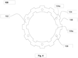
- Fig. 4 illustrates the sheath of the cable having a plurality of internal grooves, a plurality of external grooves, a plurality of internal ribs and a plurality of external ribs in accordance with an embodiment lying outside the scope of the present invention.
- the sheath 102 has the plurality of ribs 104, the plurality of grooves 106, and the plurality of strength members 108.
- the plurality of ribs 104 is formed on the outer surface of the sheath 102 and may be referred to as the plurality of external ribs.
- the sheath 102 includes a plurality of internal ribs 104a and a plurality of internal grooves 106a formed on an internal surface of the sheath 102.
- the number of the plurality of ribs 104 on the outer surface of the sheath 102 of the ribbed and grooved optical fiber cable 100 is 12.
- the number of the plurality of ribs 104 on the outer surface of the sheath 102 of the ribbed and grooved optical fiber cable 100 may vary.
- Each of the plurality of ribs 104 has height of about 0.5 millimeter. Alternatively, height of the plurality of ribs 104 may vary.
- the sheath 102 includes the plurality of grooves 106, and the plurality of grooves 106 is also called the plurality of external grooves. Further, the sheath 102 includes a plurality of internal grooves 106a formed on an inner/internal surface of the sheath 102.
- the plurality of internal grooves 106a reduces the mass of the ribbed and grooved optical fiber cable 100. In addition, the plurality of internal grooves 106a increases free space for optical fibers or ribbons in the ribbed and grooved optical fiber cable 100.
- the plurality of external grooves 106 is formed on the outer surface of the sheath 102.
- the plurality of internal grooves 106a on the inner surface of the sheath 102 is 6.
- the plurality of internal grooves 106a on the inner surface of the sheath 102 may vary.
- the plurality of internal grooves 106a has a depth of about 0.5 millimeter.
- the depth of the plurality of internal grooves 106a may vary.
- the plurality of external grooves 106 on the outer surface of the sheath 102 is 12.
- the plurality of external grooves 106 on the outer of the sheath 102 may vary.
- the area of the ribbed and grooved optical fiber cable 100 corresponding to 12 external ribs and 6 internal grooves is about 41.05 millimeter square.
- area of the cable may vary depending upon internal diameter of the cable, external diameter of the cable, number of the plurality of ribs 104.
- the ribbed and grooved optical fiber cable 100 has deformation of about 1.80 millimeter under crushing load at 500 Newton per 100 millimeter.
- deformation of the ribbed and grooved optical fiber cable 100 may vary.
- deformation of the ribbed and grooved optical fiber cable 100 may vary depending upon the plurality of parameters.
- the plurality of parameters includes but may not be limited to number of the plurality of ribs 104 and number of the plurality of internal grooves 106a and the plurality of external grooves 106, width and height of the plurality of ribs 104 and the plurality of grooves 106, inside and outside diameter of the ribbed and grooved optical fiber cable 100 , number of the plurality of strength members 108 in the sheath 102, and material grade of the ribbed and grooved optical fiber cable 100.
- Fig. 5 illustrates the sheath of the cable having embedded strength members.
- the plurality of ribs 104 includes a first type of ribs and a second type of ribs.
- Each rib of the first type of ribs has a large size.
- Each rib of the second type of ribs has a smaller size as compared to the first type of ribs.
- height of the first type of ribs i.e. the first height
- height of the second type of ribs i.e. the second height).
- the number of the first type of ribs is equal to the number of the second type of ribs.
- the first type of ribs and the second type of ribs are arranged alternately to each other.
- the alternate arrangement of the first type of ribs and the second type of ribs reduce weight of the ribbed and grooved optical fiber cable 100.
- the alternate arrangement of the first type of ribs and the second type of ribs reduces friction in the ribbed and grooved optical fiber cable 100.
- the number of the first type of ribs is 9.
- the number of the first type of ribs may vary.
- the number of the second type of ribs is 9.
- the number of the second type of ribs may vary.
- the plurality of ribs 104 (first type of ribs and second type of ribs) is 18. Alternatively, the plurality of ribs 104 may vary. Further, the plurality of grooves 106 in the ribbed and grooved optical fiber cable 100 is 18. Alternatively, the plurality of grooves 106 may vary. In an embodiment, the area of the ribbed and grooved optical fiber cable 100 corresponding to 18 ribs is about 42.17 millimeter square. Alternatively, area of the ribbed and grooved optical fiber cable 100 may vary depending upon internal diameter of the cable, external diameter of the cable, number of the plurality of ribs 104. The ribbed and grooved optical fiber cable 100 has deformation of about 0.45 millimeter under crushing load at 500 Newton per 100 millimeter. Alternatively, deformation of the ribbed and grooved optical fiber cable 100 may vary.
- deformation of the ribbed and grooved optical fiber cable 100 may vary depending upon the plurality of parameters.
- the plurality of parameters includes but may not be limited to number of the plurality of ribs 104 and number of internal grooves of the plurality of grooves 106, width and height of the plurality of ribs 104 and the plurality of grooves 106, inside and outside diameter of the ribbed and grooved optical fiber cable 100, number of the plurality of strength members 108 in the sheath 102, and material grade of the ribbed and grooved optical fiber cable 100.
- the plurality of ribs 104 and the plurality of grooves 106 of the ribbed and grooved optical fiber cable 100 are arranged alternately to each other on the outer surface of the sheath 102.
- height of the first type of ribs of the ribbed and grooved optical fiber cable 100 i.e. the first height is 0.5 millimeter.
- the height of the second type of ribs of the ribbed and grooved optical fiber cable 100 i.e. the second height is 0.25 millimeter.
- height of the first type of ribs (i.e. the first height) of the ribbed and grooved optical fiber cable 100 may vary.
- height of the second type of ribs (i.e. the second height) of the ribbed and grooved optical fiber cable 100 may vary.
- first type of ribs and the second type of ribs enables high crushing performance.
- first type of ribs support the second type of ribs when a fixed crush load is applied on the ribbed and grooved optical fiber cable 100 that enables high crushing performance as compared to the similar design of cable where all the ribs have equal height.
- the number of the first type of ribs and the second type of ribs is an odd number.
- the odd number of the first type of ribs and the second type of ribs ensures that each of the first type of ribs is diametrically opposite to the corresponding rib of the second type of ribs.
- the odd number of the first type of ribs and the second type of ribs eliminates dependency on orientation of the fixed crush load on the ribbed and grooved optical fiber cable 100.
- the sheath 102 having more number of the first type of ribs (large sized ribs) has small lateral deformations. Adjacent ribs provide support to the cross section of the ribbed and grooved optical fiber cable 100 when the cable starts to deform and take an elliptical shape.
- the sheath 102 has less plurality of ribs 104. The plurality of ribs 104 are more spaced out in the sheath 102 due to less number of plurality of ribs 104.
- the sheath 102 with less plurality of ribs 104 does not provide support to the cross section of the ribbed and grooved optical fiber cable 100 even at low forces.
- Fig. 6 illustrates the sheath of the cable having the plurality of grooves and the plurality of ribs extruded in a linear manner along a length of the cable in accordance with an embodiment outside the scope of the present invention.
- the plurality of ribs 104 and the plurality of grooves 106 are extruded longitudinally along the length of the ribbed and grooved optical fiber cable 100.
- Fig. 7 illustrates the sheath of the cable having the plurality of grooves and the plurality of ribs extruded helically along the length of the cable in accordance with an embodiment lying outside the scope of the present invention.
- the plurality of ribs 104 and the plurality of grooves 106 are extruded helically along the length of the ribbed and grooved optical fiber cable 100.
- the plurality of ribs 104 and the plurality of grooves 106 are extruded in SZ fashion.
- the plurality of ribs 104 and the plurality of grooves 106 may be extruded in any suitable shape.
- Fig. 8 illustrates the sheath of the cable having the plurality of internal grooves, the plurality of external grooves, the plurality of internal ribs and the plurality of external ribs in accordance with an embodiment of the present invention.
- the sheath 102 includes the plurality of ribs 104 on the external surface of the sheath (referred to as the plurality of external ribs 104 with reference to Fig. 8 ), the plurality of grooves 106 on the external surface of the sheath (referred to as the plurality of external grooves 106 with reference to Fig. 8 ), the plurality of internal ribs 104a, the plurality of internal grooves 106a and the plurality of strength members 108.
- the plurality of ribs 104 includes the first type of ribs and the second type of ribs.
- Each rib of the first type of ribs has a large size.
- Each rib of the second type of ribs has a smaller size as compared to the first type of ribs.
- the height of each of the first type of ribs i.e. the first height
- the height of each of the second type of ribs is larger than the height of each of the second type of ribs (i.e. the second height).
- the number of the first type of ribs is equal to the number of the second type of ribs.
- the first type of ribs and the second type of ribs are arranged alternately to each other.
- the alternate arrangement of the first type of ribs and the second type of ribs reduces weight of the ribbed and grooved optical fiber cable 100.
- the alternate arrangement of the first type of ribs and the second type of ribs reduces friction in the ribbed and grooved optical fiber cable 100.
- the number of the first type of ribs is 6.
- the number of the first type of ribs may vary.
- the number of the second type of ribs is 6.
- the number of the second type of ribs may vary.
- the plurality of ribs 104 (first type of ribs and second type of ribs) is 12.
- the plurality of ribs 104 may vary.
- the ribbed and grooved optical fiber cable 100 includes the plurality of external grooves 106.
- the plurality of grooves 106a corresponds to the internal grooves.
- the plurality of ribs 104 surrounds the plurality of grooves 106.
- the plurality of grooves 106a (the internal grooves) are formed on the inner surface of the sheath 102. Further, the number of the internal grooves on the inner surface of the sheath 102 is 6. Alternatively, the number of the internal grooves on the inner surface of the sheath 102 may vary.
- the first height may be in a range of 0.2-1.0 millimeter (mm) and the second height may be in the range of 0.1-0.5 millimeter.
- the first height may be in the range of 0.1-0.5 millimeter and the second height may be in the range of 0.2-1.0 millimeter.
- the plurality of ribs 104 may have a width in the range of 0.8-6.5 millimeter.
- the plurality of grooves 106 may have a width in the range of 0.8-6.5 millimeter.
- the alternate arrangement of the first type of ribs and the second type of ribs enables high crushing performance.
- the first type of ribs support the second type of ribs when a fixed crush load is applied on the ribbed and grooved optical fiber cable 100 that enables high crushing performance as compared to the similar design of cable where all the ribs have equal height.
- the number of the first type of ribs and the second type of ribs is an odd number.
- the odd number of the first type of ribs and the second type of ribs ensures that each of the first type of ribs is diametrically opposite to the corresponding rib of the second type of ribs. Moreover, the odd number of the first type of ribs and the second type of ribs eliminates dependency on orientation of the fixed crush load on the ribbed and grooved optical fiber cable 100.
- Fig. 9 illustrates the strength member of the cable coated with a coating material in accordance with an embodiment lying outside the scope of the present invention.
- the plurality of strength members 108 embedded in the sheath 102 may have a circular shape or any other suitable shape.
- the one or more strength members 108 are coated with the coating material having at least one of an ultraviolet (UV) curable water swellable resin composition (or resin) and a thick layer of ethylene acrylic acid (EAA) to prevent water ingression in the ribbed and grooved optical fiber cable 100 as without the coating material, the water may seep through the one or more strength members 108 embedded in the sheath 102.
- UV ultraviolet
- EAA ethylene acrylic acid
- the thick layer of ethylene acrylic acid (EAA) 202 may be coated on the one or more strength members 200 before embedding in the sheath 102.
- the ethylene acrylic acid (EAA) provides a good adhesion between the one or more strength members 108 and the sheath 102 to further prevent from water ingression.
- the UV curable water swellable resin composition 202 is coated on the one or more strength members 200 and cured before embedding in the sheath 102.
- the resin composition comes in contact with water, it swells and blocks the way for water to avoid penetration in the core of the ribbed and grooved optical fiber cable 100.
- the core includes the plurality of optical fibers.
- the plurality of optical fibers may be incorporated in the core as a plurality of loose tube optical fibers, a plurality of tight buffered optical fibers, a group or stack of optical fiber ribbons or the like., which is enclosed by the sheath 102.
- the UV curable water swellable resin composition can include, but not limited to, acrylic acid, phenyl bis(2,4,6-trimethylbenzoyl)-phosphine oxide and oxybis(methyl-2,1-ethanediyl) diacrylate.
- the UV curable water swellable resin composition may be applied directly on the one or more strength members 108 or above a thin layer of ethylene acrylic acid (EAA) having a thickness of 25 ⁇ 5 microns.
- EAA ethylene acrylic acid
- the thin layer of ethylene acrylic acid (EAA) helps to achieve better adhesion of the one or more strength members with material of the sheath.
- the coating 202 may have a thickness, preferably, in a range of 40 microns to 60 microns as a thinner layer of the coating material may lead to water ingression.
- a sheathing tool has strength member embedding holes that supports the coating thickness upto 50-60 microns. Beyond this, abrasion will occur and will further lead to waste creation.
- the thickness of the coating may vary.
- the one or more strength members 108 may be made of fiber reinforced plastic (FRP), aramid reinforced plastic (ARP) or any other suitable material.
- Fig.8 illustrates the sheath of the cable in accordance with the present invention.
- the sheath 102 has the plurality of ribs 104, the plurality of grooves 106 and the plurality of strength members 108.
- the sheath 102 encloses the plurality of optical fibers.
- the plurality of grooves 106 on the outer surface of the sheath 102 may be called as the plurality of external grooves or external grooves.
- the plurality of grooves 106 on the inner surface of the sheath 102 may be called as the plurality of internal grooves or internal grooves.
- the plurality of ribs 104 on the outer surface of the sheath 102 may be called as the plurality of external ribs or external ribs.
- the plurality of ribs 104a on the inner surface of the sheath 102 may be called as the plurality of internal ribs or internal ribs.
- the plurality of ribs 104 includes a first type of ribs and a second type of ribs.
- Each rib of the first type of ribs may have a larger size than each rib of the second type of ribs.
- each rib of the first type of ribs may have smaller size than each rib of the second type of ribs.
- the ribbed and grooved optical fiber cable 100 having the plurality of ribs 104 may have at least two heights.
- the first type of ribs may have the first height and the second type of ribs may have the second height.
- the first type of ribs may have a larger height than of the second type of ribs.
- the first type of ribs may have smaller height than of the second type of ribs.
- the plurality of ribs 104 and the plurality of grooves 106 of the ribbed and grooved optical fiber cable 100 are arranged alternately to each other on the outer surface of the sheath 102.
- the height (i.e. the first height) of the first type of ribs and the height (i.e. the second height) of the second type of ribs of the ribbed and grooved optical fiber cable 100 may vary. Further, height of each of the plurality of grooves 106 is equal. Alternatively, height of each of the plurality of grooves 106 may vary.
- the sheath 102 having more number of the first type of ribs (large sized ribs) has small lateral deformations.
- Adjacent ribs provide support to the cross section of the ribbed and grooved optical fiber cable 100 when the cable starts to deform and take an elliptical shape.
- the sheath 102 has less plurality of ribs 104.
- the plurality of ribs 104 are more spaced out in the sheath 102 due to less number of plurality of ribs 104.
- the sheath 102 with less plurality of ribs 104 does not provide support to the cross section of the ribbed and grooved optical fiber cable 100 even at low forces.
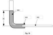
- Fig. 10 illustrates a water penetration test arrangement for the cable in accordance with an embodiment lying outside the scope of the present invention.
- the sample was pre-soaked in a bucket of water to a depth of 100 mm ⁇ 10 mm for 10 min before the test.
- the cable sample 302 of 3 meters was taken and a watertight seal 304 was applied to allow a 1m (H) of water-head 306 to be applied for 24 hours.
- the sheath 102 and the plurality of external ribs 104 may be made of same material such as polyvinyl chloride, polyethylene (such as High Density Polyethylene (HDPE), Medium Density Polyethylene, and Low Density Polyethylene), polyurethane, thermoplastic rubber/elastomer, thermoplastic chlorinated polyethylene, thermoset polyolefins or combination thereof.
- polyvinyl chloride such as High Density Polyethylene (HDPE), Medium Density Polyethylene, and Low Density Polyethylene
- polyurethane such as High Density Polyethylene (HDPE), Medium Density Polyethylene, and Low Density Polyethylene
- thermoplastic rubber/elastomer such as thermoplastic rubber/elastomer, thermoplastic chlorinated polyethylene, thermoset polyolefins or combination thereof.
- the sheath 102 and the plurality of external ribs 104 may be made of different materials.
- the plurality of external ribs 104 and the plurality of external grooves 106 are one or more of a rectangular shape with rounded edges, a pointy triangle shape, a circular shape, a curve-type shape or other suitable shape. Further, the plurality of external ribs 104 has a height (first height or second height or both) in a range of 0.1-2.0 millimeters, the plurality of external ribs 104 has a width in a range of 0.4-20 millimeters and the plurality of external grooves 106 has a width in a range of 0.4-20 millimeters.
- the optical fiber ribbed and grooved optical fiber cable 100 has a diameter in a range of 11 to 13 millimeters, and the optical fiber cable has a blowing of more than 1100 meters in the duct with an inner diameter of 14 millimeters and an outer diameter of 18 millimeters.
- the plurality of internal ribs have the height in the range of 0.1-1.0 millimeter and the width in the range of 1.2-2.5 millimeters. Further, the plurality of internal grooves have the width in the range of 1.2-2.5 millimeters.
- the ribbed and grooved cable that reduces coefficient of friction between a cable sheath and a duct.
- the ribbed and grooved cable has embedded strength member(s) in the cable sheath with a water blocking coating to provide mechanical strength and ease of blowing to the ribbed and grooved cable and to prevent water ingression inside the ribbed and grooved cable.
- the inner grooves reduce mass of the ribbed and grooved cable while increasing free space for optical fibers or ribbons in the ribbed and grooved cable.
- the present disclosure provides advantages such as a high blowing performance, reduced mass of the cable, increased free space for optical fibers or ribbons in the cable, large and irregular surface area, increased drag force, reduced coefficient of friction between the sheath and the duct, and better crushing behaviour.
- Disjunctive language such as the phrase "at least one of X, Y, Z," unless specifically stated otherwise, is otherwise understood with the context as used in general to present that an item, term, etc., may be either X, Y, or Z, or any combination thereof (e.g., X, Y, and/or Z). Thus, such disjunctive language is not generally intended to, and should not, imply that certain embodiments require at least one of X, at least one of Y, or at least one of Z to each be present.
Landscapes
- Physics & Mathematics (AREA)
- General Physics & Mathematics (AREA)
- Optics & Photonics (AREA)
- Light Guides In General And Applications Therefor (AREA)
- Insulated Conductors (AREA)
Claims (15)
- Câble à fibres cannelé et rainuré (100) comprenant :un noyau avec une pluralité de fibres optiques ;une gaine (102) enveloppant le noyau,dans lequel la gaine (102) présente une surface externe et une surface interne, dans lequel la surface externe de la gaine (102) présente une pluralité de nervures externes (104) et une pluralité de rainures externes 106) ; etau moins un parmi un ou plusieurs éléments de résistance (108) incorporés dans la gaine (102), une pluralité de nervures (104) et de rainures (106) sur une surface externe de la gaine (102), et une pluralité de nervures (104a) et de rainures (106a) sur une surface interne de la gaine (102), dans lequel la pluralité de nervures (104) ont une hauteur variable, dans lequel les un ou plusieurs éléments de résistance (108) sont revêtus d'un matériau de revêtement bloquant l'eau ayant au moins une parmi une composition de résine gonflable à l'eau durcissable aux UV (UV) et une couche d'acide éthylène acrylique (EAA).
- Câble à fibres optiques cannelé et rainuré (100) selon la revendication 1, dans lequel la pluralité de nervures externes (104) sont agencées alternativement sur toute la surface externe de la gaine (102) du câble à fibres optiques (100).
- Câble à fibres optiques cannelé et rainuré (100) selon la revendication 1 ou la revendication 2, dans lequel la pluralité de nervures externes (104) ont au moins deux hauteurs incluant une première hauteur et une seconde hauteur ; et dans lequel la première hauteur est dans une plage de 0,2 millimètre à 1,0 millimètre et la seconde hauteur est dans la plage de 0,1 millimètre à 0,5 millimètre.
- Câble à fibres optiques cannelé et rainuré (100) selon la revendication 3, dans lequel la pluralité de nervures externes (104) ayant la première hauteur et la seconde hauteur sont agencées de manière à ce que la pluralité de nervures externes (104) ayant la première hauteur et la pluralité de nervures externes (104) ayant la seconde hauteur soient positionnées en diagonale l'une par rapport à l'autre.
- Câble à fibres optiques cannelé et rainuré (100) selon une quelconque revendication précédente, dans lequel la pluralité de nervures externes (104) et la pluralité de rainures externes (106) ont une largeur dans la plage de 1,2 millimètre à 2,5 millimètres.
- Câble à fibres optiques cannelé et rainuré (100) selon une quelconque revendication précédente, dans lequel une forme de la pluralité de nervures externes (104) et de la pluralité de rainures externes (106) est l'une quelconque parmi une forme rectangulaire avec des bords arrondis, une forme triangulaire pointue, une forme circulaire, une forme de type courbe ou toute forme appropriée.
- Câble à fibres optiques cannelé et rainuré (100) selon une quelconque revendication précédente, dans lequel la gaine (102) et la pluralité de nervures externes (104) sont constituées d'un même matériau ou de matériaux différents choisis parmi le polychlorure de vinyle, polyéthylène (tel que le polyéthylène haute densité (HDPE), polyéthylène moyenne densité, et polyéthylène basse densité), polyuréthane, caoutchouc/élastomère thermoplastique, polyéthylène chloré thermoplastique, polyoléfines thermodurcissables ou leur combinaison.
- Câble à fibres optiques cannelé et rainuré (100) selon une quelconque revendication précédente, dans lequel le câble à fibres optiques cannelé et rainuré (100) a un diamètre dans la plage de 11 millimètres à 13 millimètres et un soufflage de plus de 1 100 mètres dans un conduit d'un diamètre intérieur de 14 millimètres et d'un diamètre extérieur de 18 millimètres.
- Câble à fibres optiques cannelé et rainuré (100) selon une quelconque revendication précédente, dans lequel la pluralité de nervures internes (104) et la pluralité de rainures internes (106) sont agencées alternativement sur toute la surface interne de la gaine (102).
- Câble à fibres optiques cannelé et rainuré (100) selon la revendication 9, dans lequel une forme de la pluralité de nervures internes (104) et de la pluralité de rainures internes (106) présente une forme rectangulaire avec des bords arrondis, une forme triangulaire pointue, une forme circulaire, une forme de type courbe ou une forme similaire.
- Câble à fibres optiques cannelé et rainuré (100) selon la revendication 9, dans lequel la pluralité de nervures internes (104) a une hauteur dans une plage de 0,1 millimètre à 1,0 millimètre et une largeur dans la plage de 1,2 millimètre à 2,5 millimètres.
- Câble à fibres optiques cannelé et rainuré (100) selon une quelconque revendication précédente, dans lequel la composition de résine gonflable à l'eau durcissable aux UV est appliquée directement sur les un ou plusieurs éléments de résistance (108) ou au-dessus d'une fine couche d'acide éthylène acrylique (EAA) en passant à travers une ou plusieurs chambres UV pour durcir la composition de résine gonflable à l'eau durcissable aux UV ; et la composition de résine gonflable à l'eau durcissable aux UV comporte acide acrylique, oxyde de phényl bis(2,4,6-triméthylbenzoyl)-phosphine et oxybis(méthyl-2,1-éthanediyl)diacrylate.
- Câble à fibres optiques cannelé et rainuré (100) selon une quelconque revendication précédente, dans lequel le matériau de revêtement bloquant l'eau appliqué sur les un ou plusieurs éléments de résistance (108) a une épaisseur de 50±10 microns.
- Câble à fibres optiques cannelé et rainuré (100) selon une quelconque revendication précédente, dans lequel le câble à fibres optiques cannelé et rainuré (100) passe un essai de pénétration d'eau à une pression de 0,1 bar en tête d'eau appliquée à un câble optique de 3 mètres pendant au moins 24 heures.
- Câble à fibres optiques cannelé et rainuré (100) selon une quelconque revendication précédente, dans lequel les un ou plusieurs éléments de résistance (108) sont constitués d'un plastique renforcé de fibres (FRP), plastique renforcé d'aramide (ARP) ou matériau similaire.
Applications Claiming Priority (2)
| Application Number | Priority Date | Filing Date | Title |
|---|---|---|---|
| IN202011024930 | 2020-06-13 | ||
| IN202011045978 | 2020-10-22 |
Publications (2)
| Publication Number | Publication Date |
|---|---|
| EP3923053A1 EP3923053A1 (fr) | 2021-12-15 |
| EP3923053B1 true EP3923053B1 (fr) | 2025-02-12 |
Family
ID=76483023
Family Applications (1)
| Application Number | Title | Priority Date | Filing Date |
|---|---|---|---|
| EP21179369.0A Active EP3923053B1 (fr) | 2020-06-13 | 2021-06-14 | Câble à nervure et rainuré ayant un élément de résistance incorporé avec un revêtement bloquant l'eau |
Country Status (2)
| Country | Link |
|---|---|
| US (1) | US11619796B2 (fr) |
| EP (1) | EP3923053B1 (fr) |
Families Citing this family (7)
| Publication number | Priority date | Publication date | Assignee | Title |
|---|---|---|---|---|
| HUE067399T2 (hu) | 2018-10-11 | 2024-10-28 | Fujikura Ltd | Optikai kábel |
| US20230213716A1 (en) * | 2021-12-30 | 2023-07-06 | Sterlite Technologies Limited | Ribbed and grooved sheath for optical fiber cable |
| KR102587828B1 (ko) * | 2022-11-14 | 2023-10-11 | 혜성씨앤씨주식회사 | 피복 내측 보강돌기 사이에 인장재를 구비한 광케이블 |
| CN116609898B (zh) * | 2023-04-27 | 2026-01-09 | 汕头高新区奥星光通信设备有限公司 | 一种松套嵌合式光纤带光缆及其制造方法 |
| EP4650843A1 (fr) | 2024-05-14 | 2025-11-19 | Sterlite Technologies Limited | Câble blindé à fibres optiques |
| EP4650844A1 (fr) | 2024-05-14 | 2025-11-19 | Sterlite Technologies Limited | Câble à fibres optiques blindé à accès facile |
| WO2026003475A1 (fr) * | 2024-06-27 | 2026-01-02 | Lwf Uk Limited | Perfectionnements apportés ou se rapportant à des câbles à fibres optiques |
Family Cites Families (10)
| Publication number | Priority date | Publication date | Assignee | Title |
|---|---|---|---|---|
| JPH0833502B2 (ja) * | 1988-08-11 | 1996-03-29 | 宇部日東化成株式会社 | 光ファイバ担持用スペーサ |
| JP2000019366A (ja) * | 1998-04-28 | 2000-01-21 | Fujikura Ltd | 圧送用光ファイバユニット |
| US6573456B2 (en) * | 1999-01-11 | 2003-06-03 | Southwire Company | Self-sealing electrical cable having a finned inner layer |
| US6639152B2 (en) * | 2001-08-25 | 2003-10-28 | Cable Components Group, Llc | High performance support-separator for communications cable |
| US7123801B2 (en) * | 2004-11-18 | 2006-10-17 | Prysmian Communications Cables And Systems Usa, Llc | Optical fiber cable with fiber receiving jacket ducts |
| US7406232B2 (en) * | 2006-08-31 | 2008-07-29 | Corning Cable Systems Llc | Non-round fiber optic cable having improved major axis crush resistance |
| CN202119952U (zh) * | 2011-05-28 | 2012-01-18 | 四川汇源光通信有限公司 | 表面具有凹凸纹槽的绞合式微型气吹光缆 |
| JP2013171220A (ja) * | 2012-02-22 | 2013-09-02 | Fujikura Ltd | 光ファイバケーブル |
| US20140119699A1 (en) * | 2012-10-25 | 2014-05-01 | Nexans | Optical fiber cable having spline profiled insulation |
| HUE067399T2 (hu) | 2018-10-11 | 2024-10-28 | Fujikura Ltd | Optikai kábel |
-
2021
- 2021-06-14 EP EP21179369.0A patent/EP3923053B1/fr active Active
- 2021-06-14 US US17/347,080 patent/US11619796B2/en active Active
Also Published As
| Publication number | Publication date |
|---|---|
| US11619796B2 (en) | 2023-04-04 |
| EP3923053A1 (fr) | 2021-12-15 |
| US20210389542A1 (en) | 2021-12-16 |
Similar Documents
| Publication | Publication Date | Title |
|---|---|---|
| EP3923053B1 (fr) | Câble à nervure et rainuré ayant un élément de résistance incorporé avec un revêtement bloquant l'eau | |
| US20190196125A1 (en) | Armored fiber optic assemblies and methods of forming fiber optic assemblies | |
| CN101957482B (zh) | 铠装光纤组件及形成光纤组件的方法 | |
| CN101726814B (zh) | 铠装光纤组件及其制造方法 | |
| US8494328B2 (en) | Armored fiber optic assemblies | |
| US6934452B2 (en) | Optical fiber cables | |
| US20060291787A1 (en) | Fiber optic cable having strength component | |
| CN101120277A (zh) | 低收缩电信光缆及其制造方法 | |
| CN101153942B (zh) | 松管光波导光缆 | |
| EP4206776A1 (fr) | Gaine nervurée et rainurée pour câble à fibre optique | |
| EP1982222B1 (fr) | Cable a fibres optiques susceptible d'etre installe dans des microconduits de petit diametre par circulation d'air ou enfoncement | |
| US20190025531A1 (en) | Optical cable and manufacturing method | |
| US20240176088A1 (en) | Optical cable with dielectric strength elements and toneable element | |
| KR100396281B1 (ko) | 루즈 튜브 리본 광케이블 | |
| US6845789B2 (en) | High density fiber optic cable inner ducts | |
| CN1950735A (zh) | 缓冲光波导管 | |
| EP1818703A1 (fr) | Câble à fibre optique ajusté pour une installation soufflée ou une installation de poussée dans les micro-conduite petit diamètre | |
| US20250298207A1 (en) | Optical fibre cable with improved pneumatic feeding | |
| EP4212935A1 (fr) | Câble à fibres optiques avec tubes multi-couches | |
| AU2015203046B2 (en) | Armored fiber optic assemblies and methods of forming fiber optic assemblies | |
| CN116783530A (zh) | 具有可卷曲带单元和弹性体层的光纤线缆结构 | |
| EP2204682A2 (fr) | Guide de fibre amélioré pour câbles à fibres optiques |
Legal Events
| Date | Code | Title | Description |
|---|---|---|---|
| STAA | Information on the status of an ep patent application or granted ep patent |
Free format text: STATUS: UNKNOWN |
|
| PUAI | Public reference made under article 153(3) epc to a published international application that has entered the european phase |
Free format text: ORIGINAL CODE: 0009012 |
|
| STAA | Information on the status of an ep patent application or granted ep patent |
Free format text: STATUS: THE APPLICATION HAS BEEN PUBLISHED |
|
| AK | Designated contracting states |
Kind code of ref document: A1 Designated state(s): AL AT BE BG CH CY CZ DE DK EE ES FI FR GB GR HR HU IE IS IT LI LT LU LV MC MK MT NL NO PL PT RO RS SE SI SK SM TR |
|
| B565 | Issuance of search results under rule 164(2) epc |
Effective date: 20211117 |
|
| STAA | Information on the status of an ep patent application or granted ep patent |
Free format text: STATUS: REQUEST FOR EXAMINATION WAS MADE |
|
| 17P | Request for examination filed |
Effective date: 20220921 |
|
| RBV | Designated contracting states (corrected) |
Designated state(s): AL AT BE BG CH CY CZ DE DK EE ES FI FR GB GR HR HU IE IS IT LI LT LU LV MC MK MT NL NO PL PT RO RS SE SI SK SM TR |
|
| GRAP | Despatch of communication of intention to grant a patent |
Free format text: ORIGINAL CODE: EPIDOSNIGR1 |
|
| STAA | Information on the status of an ep patent application or granted ep patent |
Free format text: STATUS: GRANT OF PATENT IS INTENDED |
|
| INTG | Intention to grant announced |
Effective date: 20240911 |
|
| RAP3 | Party data changed (applicant data changed or rights of an application transferred) |
Owner name: STERLITE TECHNOLOGIES LIMITED |
|
| GRAS | Grant fee paid |
Free format text: ORIGINAL CODE: EPIDOSNIGR3 |
|
| GRAA | (expected) grant |
Free format text: ORIGINAL CODE: 0009210 |
|
| STAA | Information on the status of an ep patent application or granted ep patent |
Free format text: STATUS: THE PATENT HAS BEEN GRANTED |
|
| AK | Designated contracting states |
Kind code of ref document: B1 Designated state(s): AL AT BE BG CH CY CZ DE DK EE ES FI FR GB GR HR HU IE IS IT LI LT LU LV MC MK MT NL NO PL PT RO RS SE SI SK SM TR |
|
| REG | Reference to a national code |
Ref country code: GB Ref legal event code: FG4D |
|
| REG | Reference to a national code |
Ref country code: CH Ref legal event code: EP |
|
| REG | Reference to a national code |
Ref country code: DE Ref legal event code: R096 Ref document number: 602021025875 Country of ref document: DE |
|
| REG | Reference to a national code |
Ref country code: IE Ref legal event code: FG4D |
|
| REG | Reference to a national code |
Ref country code: NL Ref legal event code: MP Effective date: 20250212 |
|
| PG25 | Lapsed in a contracting state [announced via postgrant information from national office to epo] |
Ref country code: RS Free format text: LAPSE BECAUSE OF FAILURE TO SUBMIT A TRANSLATION OF THE DESCRIPTION OR TO PAY THE FEE WITHIN THE PRESCRIBED TIME-LIMIT Effective date: 20250512 |
|
| PG25 | Lapsed in a contracting state [announced via postgrant information from national office to epo] |
Ref country code: FI Free format text: LAPSE BECAUSE OF FAILURE TO SUBMIT A TRANSLATION OF THE DESCRIPTION OR TO PAY THE FEE WITHIN THE PRESCRIBED TIME-LIMIT Effective date: 20250212 |
|
| PG25 | Lapsed in a contracting state [announced via postgrant information from national office to epo] |
Ref country code: PL Free format text: LAPSE BECAUSE OF FAILURE TO SUBMIT A TRANSLATION OF THE DESCRIPTION OR TO PAY THE FEE WITHIN THE PRESCRIBED TIME-LIMIT Effective date: 20250212 |
|
| PG25 | Lapsed in a contracting state [announced via postgrant information from national office to epo] |
Ref country code: ES Free format text: LAPSE BECAUSE OF FAILURE TO SUBMIT A TRANSLATION OF THE DESCRIPTION OR TO PAY THE FEE WITHIN THE PRESCRIBED TIME-LIMIT Effective date: 20250212 |
|
| PGFP | Annual fee paid to national office [announced via postgrant information from national office to epo] |
Ref country code: GB Payment date: 20250606 Year of fee payment: 5 |
|
| REG | Reference to a national code |
Ref country code: LT Ref legal event code: MG9D |
|
| PG25 | Lapsed in a contracting state [announced via postgrant information from national office to epo] |
Ref country code: NO Free format text: LAPSE BECAUSE OF FAILURE TO SUBMIT A TRANSLATION OF THE DESCRIPTION OR TO PAY THE FEE WITHIN THE PRESCRIBED TIME-LIMIT Effective date: 20250512 Ref country code: IS Free format text: LAPSE BECAUSE OF FAILURE TO SUBMIT A TRANSLATION OF THE DESCRIPTION OR TO PAY THE FEE WITHIN THE PRESCRIBED TIME-LIMIT Effective date: 20250612 |
|
| PG25 | Lapsed in a contracting state [announced via postgrant information from national office to epo] |
Ref country code: NL Free format text: LAPSE BECAUSE OF FAILURE TO SUBMIT A TRANSLATION OF THE DESCRIPTION OR TO PAY THE FEE WITHIN THE PRESCRIBED TIME-LIMIT Effective date: 20250212 |
|
| PG25 | Lapsed in a contracting state [announced via postgrant information from national office to epo] |
Ref country code: HR Free format text: LAPSE BECAUSE OF FAILURE TO SUBMIT A TRANSLATION OF THE DESCRIPTION OR TO PAY THE FEE WITHIN THE PRESCRIBED TIME-LIMIT Effective date: 20250212 |
|
| PG25 | Lapsed in a contracting state [announced via postgrant information from national office to epo] |
Ref country code: LV Free format text: LAPSE BECAUSE OF FAILURE TO SUBMIT A TRANSLATION OF THE DESCRIPTION OR TO PAY THE FEE WITHIN THE PRESCRIBED TIME-LIMIT Effective date: 20250212 Ref country code: PT Free format text: LAPSE BECAUSE OF FAILURE TO SUBMIT A TRANSLATION OF THE DESCRIPTION OR TO PAY THE FEE WITHIN THE PRESCRIBED TIME-LIMIT Effective date: 20250612 |
|
| PG25 | Lapsed in a contracting state [announced via postgrant information from national office to epo] |
Ref country code: BG Free format text: LAPSE BECAUSE OF FAILURE TO SUBMIT A TRANSLATION OF THE DESCRIPTION OR TO PAY THE FEE WITHIN THE PRESCRIBED TIME-LIMIT Effective date: 20250212 Ref country code: GR Free format text: LAPSE BECAUSE OF FAILURE TO SUBMIT A TRANSLATION OF THE DESCRIPTION OR TO PAY THE FEE WITHIN THE PRESCRIBED TIME-LIMIT Effective date: 20250513 |
|
| REG | Reference to a national code |
Ref country code: AT Ref legal event code: MK05 Ref document number: 1766571 Country of ref document: AT Kind code of ref document: T Effective date: 20250212 |
|
| PG25 | Lapsed in a contracting state [announced via postgrant information from national office to epo] |
Ref country code: SE Free format text: LAPSE BECAUSE OF FAILURE TO SUBMIT A TRANSLATION OF THE DESCRIPTION OR TO PAY THE FEE WITHIN THE PRESCRIBED TIME-LIMIT Effective date: 20250212 |
|
| PG25 | Lapsed in a contracting state [announced via postgrant information from national office to epo] |
Ref country code: SM Free format text: LAPSE BECAUSE OF FAILURE TO SUBMIT A TRANSLATION OF THE DESCRIPTION OR TO PAY THE FEE WITHIN THE PRESCRIBED TIME-LIMIT Effective date: 20250212 |
|
| PG25 | Lapsed in a contracting state [announced via postgrant information from national office to epo] |
Ref country code: DK Free format text: LAPSE BECAUSE OF FAILURE TO SUBMIT A TRANSLATION OF THE DESCRIPTION OR TO PAY THE FEE WITHIN THE PRESCRIBED TIME-LIMIT Effective date: 20250212 |
|
| PG25 | Lapsed in a contracting state [announced via postgrant information from national office to epo] |
Ref country code: IT Free format text: LAPSE BECAUSE OF FAILURE TO SUBMIT A TRANSLATION OF THE DESCRIPTION OR TO PAY THE FEE WITHIN THE PRESCRIBED TIME-LIMIT Effective date: 20250212 |
|
| PG25 | Lapsed in a contracting state [announced via postgrant information from national office to epo] |
Ref country code: AT Free format text: LAPSE BECAUSE OF FAILURE TO SUBMIT A TRANSLATION OF THE DESCRIPTION OR TO PAY THE FEE WITHIN THE PRESCRIBED TIME-LIMIT Effective date: 20250212 |
|
| PG25 | Lapsed in a contracting state [announced via postgrant information from national office to epo] |
Ref country code: EE Free format text: LAPSE BECAUSE OF FAILURE TO SUBMIT A TRANSLATION OF THE DESCRIPTION OR TO PAY THE FEE WITHIN THE PRESCRIBED TIME-LIMIT Effective date: 20250212 Ref country code: CZ Free format text: LAPSE BECAUSE OF FAILURE TO SUBMIT A TRANSLATION OF THE DESCRIPTION OR TO PAY THE FEE WITHIN THE PRESCRIBED TIME-LIMIT Effective date: 20250212 |
|
| PG25 | Lapsed in a contracting state [announced via postgrant information from national office to epo] |
Ref country code: RO Free format text: LAPSE BECAUSE OF FAILURE TO SUBMIT A TRANSLATION OF THE DESCRIPTION OR TO PAY THE FEE WITHIN THE PRESCRIBED TIME-LIMIT Effective date: 20250212 |
|
| PG25 | Lapsed in a contracting state [announced via postgrant information from national office to epo] |
Ref country code: SK Free format text: LAPSE BECAUSE OF FAILURE TO SUBMIT A TRANSLATION OF THE DESCRIPTION OR TO PAY THE FEE WITHIN THE PRESCRIBED TIME-LIMIT Effective date: 20250212 |
|
| REG | Reference to a national code |
Ref country code: DE Ref legal event code: R097 Ref document number: 602021025875 Country of ref document: DE |
|
| PLBE | No opposition filed within time limit |
Free format text: ORIGINAL CODE: 0009261 |
|
| STAA | Information on the status of an ep patent application or granted ep patent |
Free format text: STATUS: NO OPPOSITION FILED WITHIN TIME LIMIT |
|
| REG | Reference to a national code |
Ref country code: CH Ref legal event code: L10 Free format text: ST27 STATUS EVENT CODE: U-0-0-L10-L00 (AS PROVIDED BY THE NATIONAL OFFICE) Effective date: 20251224 |
|
| REG | Reference to a national code |
Ref country code: DE Ref legal event code: R119 Ref document number: 602021025875 Country of ref document: DE |
|
| 26N | No opposition filed |
Effective date: 20251113 |
|
| REG | Reference to a national code |
Ref country code: CH Ref legal event code: H13 Free format text: ST27 STATUS EVENT CODE: U-0-0-H10-H13 (AS PROVIDED BY THE NATIONAL OFFICE) Effective date: 20260127 |
|
| PG25 | Lapsed in a contracting state [announced via postgrant information from national office to epo] |
Ref country code: MC Free format text: LAPSE BECAUSE OF FAILURE TO SUBMIT A TRANSLATION OF THE DESCRIPTION OR TO PAY THE FEE WITHIN THE PRESCRIBED TIME-LIMIT Effective date: 20250212 |
|
| PG25 | Lapsed in a contracting state [announced via postgrant information from national office to epo] |
Ref country code: LU Free format text: LAPSE BECAUSE OF NON-PAYMENT OF DUE FEES Effective date: 20250614 |
|
| REG | Reference to a national code |
Ref country code: BE Ref legal event code: MM Effective date: 20250630 |
|
| PG25 | Lapsed in a contracting state [announced via postgrant information from national office to epo] |
Ref country code: IE Free format text: LAPSE BECAUSE OF NON-PAYMENT OF DUE FEES Effective date: 20250614 Ref country code: DE Free format text: LAPSE BECAUSE OF NON-PAYMENT OF DUE FEES Effective date: 20260101 |
|
| PG25 | Lapsed in a contracting state [announced via postgrant information from national office to epo] |
Ref country code: BE Free format text: LAPSE BECAUSE OF NON-PAYMENT OF DUE FEES Effective date: 20250630 |
|
| PG25 | Lapsed in a contracting state [announced via postgrant information from national office to epo] |
Ref country code: FR Free format text: LAPSE BECAUSE OF NON-PAYMENT OF DUE FEES Effective date: 20250630 |
|
| PG25 | Lapsed in a contracting state [announced via postgrant information from national office to epo] |
Ref country code: CH Free format text: LAPSE BECAUSE OF NON-PAYMENT OF DUE FEES Effective date: 20250630 |