EP3923409A1 - Module de batterie, bloc-batterie et appareil utilisant une batterie comme source d'alimentation - Google Patents
Module de batterie, bloc-batterie et appareil utilisant une batterie comme source d'alimentation Download PDFInfo
- Publication number
- EP3923409A1 EP3923409A1 EP20922493.0A EP20922493A EP3923409A1 EP 3923409 A1 EP3923409 A1 EP 3923409A1 EP 20922493 A EP20922493 A EP 20922493A EP 3923409 A1 EP3923409 A1 EP 3923409A1
- Authority
- EP
- European Patent Office
- Prior art keywords
- battery
- electrode terminal
- explosion
- electrode
- battery module
- Prior art date
- Legal status (The legal status is an assumption and is not a legal conclusion. Google has not performed a legal analysis and makes no representation as to the accuracy of the status listed.)
- Granted
Links
Images

Classifications
-
- H—ELECTRICITY
- H01—ELECTRIC ELEMENTS
- H01M—PROCESSES OR MEANS, e.g. BATTERIES, FOR THE DIRECT CONVERSION OF CHEMICAL ENERGY INTO ELECTRICAL ENERGY
- H01M50/00—Constructional details or processes of manufacture of the non-active parts of electrochemical cells other than fuel cells, e.g. hybrid cells
- H01M50/50—Current conducting connections for cells or batteries
- H01M50/572—Means for preventing undesired use or discharge
- H01M50/574—Devices or arrangements for the interruption of current
- H01M50/578—Devices or arrangements for the interruption of current in response to pressure
-
- H—ELECTRICITY
- H01—ELECTRIC ELEMENTS
- H01M—PROCESSES OR MEANS, e.g. BATTERIES, FOR THE DIRECT CONVERSION OF CHEMICAL ENERGY INTO ELECTRICAL ENERGY
- H01M50/00—Constructional details or processes of manufacture of the non-active parts of electrochemical cells other than fuel cells, e.g. hybrid cells
- H01M50/50—Current conducting connections for cells or batteries
- H01M50/502—Interconnectors for connecting terminals of adjacent batteries; Interconnectors for connecting cells outside a battery casing
- H01M50/507—Interconnectors for connecting terminals of adjacent batteries; Interconnectors for connecting cells outside a battery casing comprising an arrangement of two or more busbars within a container structure, e.g. busbar modules
-
- H—ELECTRICITY
- H01—ELECTRIC ELEMENTS
- H01M—PROCESSES OR MEANS, e.g. BATTERIES, FOR THE DIRECT CONVERSION OF CHEMICAL ENERGY INTO ELECTRICAL ENERGY
- H01M10/00—Secondary cells; Manufacture thereof
- H01M10/05—Accumulators with non-aqueous electrolyte
- H01M10/058—Construction or manufacture
- H01M10/0585—Construction or manufacture of accumulators having only flat construction elements, i.e. flat positive electrodes, flat negative electrodes and flat separators
-
- H—ELECTRICITY
- H01—ELECTRIC ELEMENTS
- H01M—PROCESSES OR MEANS, e.g. BATTERIES, FOR THE DIRECT CONVERSION OF CHEMICAL ENERGY INTO ELECTRICAL ENERGY
- H01M50/00—Constructional details or processes of manufacture of the non-active parts of electrochemical cells other than fuel cells, e.g. hybrid cells
- H01M50/20—Mountings; Secondary casings or frames; Racks, modules or packs; Suspension devices; Shock absorbers; Transport or carrying devices; Holders
- H01M50/204—Racks, modules or packs for multiple batteries or multiple cells
- H01M50/207—Racks, modules or packs for multiple batteries or multiple cells characterised by their shape
- H01M50/209—Racks, modules or packs for multiple batteries or multiple cells characterised by their shape adapted for prismatic or rectangular cells
-
- H—ELECTRICITY
- H01—ELECTRIC ELEMENTS
- H01M—PROCESSES OR MEANS, e.g. BATTERIES, FOR THE DIRECT CONVERSION OF CHEMICAL ENERGY INTO ELECTRICAL ENERGY
- H01M50/00—Constructional details or processes of manufacture of the non-active parts of electrochemical cells other than fuel cells, e.g. hybrid cells
- H01M50/30—Arrangements for facilitating escape of gases
- H01M50/342—Non-re-sealable arrangements
- H01M50/3425—Non-re-sealable arrangements in the form of rupturable membranes or weakened parts, e.g. pierced with the aid of a sharp member
-
- H—ELECTRICITY
- H01—ELECTRIC ELEMENTS
- H01M—PROCESSES OR MEANS, e.g. BATTERIES, FOR THE DIRECT CONVERSION OF CHEMICAL ENERGY INTO ELECTRICAL ENERGY
- H01M50/00—Constructional details or processes of manufacture of the non-active parts of electrochemical cells other than fuel cells, e.g. hybrid cells
- H01M50/50—Current conducting connections for cells or batteries
- H01M50/502—Interconnectors for connecting terminals of adjacent batteries; Interconnectors for connecting cells outside a battery casing
- H01M50/503—Interconnectors for connecting terminals of adjacent batteries; Interconnectors for connecting cells outside a battery casing characterised by the shape of the interconnectors
-
- H—ELECTRICITY
- H01—ELECTRIC ELEMENTS
- H01M—PROCESSES OR MEANS, e.g. BATTERIES, FOR THE DIRECT CONVERSION OF CHEMICAL ENERGY INTO ELECTRICAL ENERGY
- H01M50/00—Constructional details or processes of manufacture of the non-active parts of electrochemical cells other than fuel cells, e.g. hybrid cells
- H01M50/50—Current conducting connections for cells or batteries
- H01M50/502—Interconnectors for connecting terminals of adjacent batteries; Interconnectors for connecting cells outside a battery casing
- H01M50/505—Interconnectors for connecting terminals of adjacent batteries; Interconnectors for connecting cells outside a battery casing comprising a single busbar
-
- H—ELECTRICITY
- H01—ELECTRIC ELEMENTS
- H01M—PROCESSES OR MEANS, e.g. BATTERIES, FOR THE DIRECT CONVERSION OF CHEMICAL ENERGY INTO ELECTRICAL ENERGY
- H01M50/00—Constructional details or processes of manufacture of the non-active parts of electrochemical cells other than fuel cells, e.g. hybrid cells
- H01M50/50—Current conducting connections for cells or batteries
- H01M50/543—Terminals
- H01M50/552—Terminals characterised by their shape
- H01M50/553—Terminals adapted for prismatic, pouch or rectangular cells
-
- H—ELECTRICITY
- H01—ELECTRIC ELEMENTS
- H01M—PROCESSES OR MEANS, e.g. BATTERIES, FOR THE DIRECT CONVERSION OF CHEMICAL ENERGY INTO ELECTRICAL ENERGY
- H01M50/00—Constructional details or processes of manufacture of the non-active parts of electrochemical cells other than fuel cells, e.g. hybrid cells
- H01M50/50—Current conducting connections for cells or batteries
- H01M50/572—Means for preventing undesired use or discharge
- H01M50/574—Devices or arrangements for the interruption of current
-
- H—ELECTRICITY
- H01—ELECTRIC ELEMENTS
- H01M—PROCESSES OR MEANS, e.g. BATTERIES, FOR THE DIRECT CONVERSION OF CHEMICAL ENERGY INTO ELECTRICAL ENERGY
- H01M2200/00—Safety devices for primary or secondary batteries
- H01M2200/10—Temperature sensitive devices
-
- H—ELECTRICITY
- H01—ELECTRIC ELEMENTS
- H01M—PROCESSES OR MEANS, e.g. BATTERIES, FOR THE DIRECT CONVERSION OF CHEMICAL ENERGY INTO ELECTRICAL ENERGY
- H01M2200/00—Safety devices for primary or secondary batteries
- H01M2200/20—Pressure-sensitive devices
-
- H—ELECTRICITY
- H01—ELECTRIC ELEMENTS
- H01M—PROCESSES OR MEANS, e.g. BATTERIES, FOR THE DIRECT CONVERSION OF CHEMICAL ENERGY INTO ELECTRICAL ENERGY
- H01M2220/00—Batteries for particular applications
- H01M2220/20—Batteries in motive systems, e.g. vehicle, ship, plane
-
- H—ELECTRICITY
- H01—ELECTRIC ELEMENTS
- H01M—PROCESSES OR MEANS, e.g. BATTERIES, FOR THE DIRECT CONVERSION OF CHEMICAL ENERGY INTO ELECTRICAL ENERGY
- H01M50/00—Constructional details or processes of manufacture of the non-active parts of electrochemical cells other than fuel cells, e.g. hybrid cells
- H01M50/20—Mountings; Secondary casings or frames; Racks, modules or packs; Suspension devices; Shock absorbers; Transport or carrying devices; Holders
- H01M50/249—Mountings; Secondary casings or frames; Racks, modules or packs; Suspension devices; Shock absorbers; Transport or carrying devices; Holders specially adapted for aircraft or vehicles, e.g. cars or trains
-
- Y—GENERAL TAGGING OF NEW TECHNOLOGICAL DEVELOPMENTS; GENERAL TAGGING OF CROSS-SECTIONAL TECHNOLOGIES SPANNING OVER SEVERAL SECTIONS OF THE IPC; TECHNICAL SUBJECTS COVERED BY FORMER USPC CROSS-REFERENCE ART COLLECTIONS [XRACs] AND DIGESTS
- Y02—TECHNOLOGIES OR APPLICATIONS FOR MITIGATION OR ADAPTATION AGAINST CLIMATE CHANGE
- Y02E—REDUCTION OF GREENHOUSE GAS [GHG] EMISSIONS, RELATED TO ENERGY GENERATION, TRANSMISSION OR DISTRIBUTION
- Y02E60/00—Enabling technologies; Technologies with a potential or indirect contribution to GHG emissions mitigation
- Y02E60/10—Energy storage using batteries
-
- Y—GENERAL TAGGING OF NEW TECHNOLOGICAL DEVELOPMENTS; GENERAL TAGGING OF CROSS-SECTIONAL TECHNOLOGIES SPANNING OVER SEVERAL SECTIONS OF THE IPC; TECHNICAL SUBJECTS COVERED BY FORMER USPC CROSS-REFERENCE ART COLLECTIONS [XRACs] AND DIGESTS
- Y02—TECHNOLOGIES OR APPLICATIONS FOR MITIGATION OR ADAPTATION AGAINST CLIMATE CHANGE
- Y02P—CLIMATE CHANGE MITIGATION TECHNOLOGIES IN THE PRODUCTION OR PROCESSING OF GOODS
- Y02P70/00—Climate change mitigation technologies in the production process for final industrial or consumer products
- Y02P70/50—Manufacturing or production processes characterised by the final manufactured product
Definitions
- the present invention relates to the battery field, and in particular, to a battery module, a battery pack, and a battery-powered apparatus.
- Secondary batteries such as lithium-ion batteries are widely used in electronic apparatuses such as mobile phones and notebook computers due to their high energy densities and environmental friendliness.
- electronic apparatuses such as mobile phones and notebook computers due to their high energy densities and environmental friendliness.
- application of the lithium-ion batteries has been quickly expanded to gasoline-electric hybrid vehicles, vessels, energy storage systems, and the like.
- a battery typically includes a housing, an electrode assembly accommodated in the housing, and electrode terminals exposed outside the housing.
- the electrode assembly includes a positive electrode plate, a negative electrode plate, and a separator separating the positive electrode plate from the negative electrode plate.
- Medium- or large-sized devices such as electric vehicles and hybrid electric vehicles require high power and large capacity, and therefore, a plurality of batteries used therein are usually connected in groups through busbars.
- thermal runaway occurs in a specific battery due to a reason such as overcharging or a short circuit
- thermal runaway is prone to occur in a battery adjacent to the battery with thermal runaway, thus leading to thermal runaway in a plurality of batteries consecutively, which in turn causes a safety incident such as a fire or an explosion.
- an objective of the present invention is to provide a battery module, a battery pack, and a battery-powered apparatus, which can reduce a risk of thermal runaway of a battery and improve safety performance.
- the present invention provides a battery module, including a plurality of battery units and a busbar assembly.
- the plurality of battery units are arranged in a horizontal direction, where each battery unit includes a plurality of batteries stacked in a vertical direction, the plurality of batteries include a first battery and a second battery stacked in a vertical direction, the first battery and the second battery each include a first electrode terminal, a second electrode terminal, and an explosion-proof piece located between the first electrode terminal and the second electrode terminal.
- a busbar assembly electrically connects the plurality of battery units, where the busbar assembly includes a first busbar connected to the first electrode terminal of the first battery and the second electrode terminal of the second battery.
- the first busbar In a first direction perpendicular to the vertical direction and the horizontal direction, the first busbar includes a first weak zone that at least partially overlaps with the explosion-proof piece of the first battery.
- the first weak zone is configured to fracture when the explosion-proof piece of the first battery is burst, to cause an open circuit between the first battery and the second battery.
- the first busbar further has a first through hole
- the first weak zone includes a first portion and a second portion
- the first portion and the second portion are respectively located on two sides of the first through hole.
- the first portion at least partially overlaps with the explosion-proof piece
- the second portion at least partially overlaps with the explosion-proof piece.
- the explosion-proof piece of the first battery has an exposed zone, and the exposed zone is not covered by the first busbar in the first direction.
- the exposed zone includes a first exposed portion facing toward the first through hole.
- the exposed zone further includes a second exposed portion, and the second exposed portion is spaced apart from the first exposed portion.
- the first busbar further includes a first connection portion and a transition portion.
- the first connection portion is connected to the first electrode terminal of the first battery, and the first weak zone is connected to the first connection portion and the transition portion.
- the transition portion has a buffer zone, and the buffer zone is configured to: flexibly deform when a distance in the horizontal direction between the first electrode terminal of the first battery and the second electrode terminal of the second battery changes; and/or flexibly deform when a distance in the vertical direction between the first electrode terminal of the first battery and the second electrode terminal of the second battery changes.
- the first busbar further includes a second connection portion and a second weak zone.
- the second connection portion is connected to the second electrode terminal of the second battery.
- the second weak zone at least partially overlaps with the explosion-proof piece of the second battery in the first direction, and the second weak zone is connected to the transition portion and the second connection portion.
- the second weak zone is configured to fracture when the explosion-proof piece of the second battery is burst, to cause an open circuit between the first battery and the second battery.
- the buffer zone is provided obliquely relative to the vertical direction and the horizontal direction.
- the buffer zone is located in the vertical direction between the explosion-proof piece of the first battery and the explosion-proof piece of the second battery.
- the buffer zone includes a plurality of arched structures.
- the first electrode terminal and the second electrode terminal of the first battery are arranged in the horizontal direction.
- the first electrode terminal and the second electrode terminal of the second battery are arranged in the horizontal direction.
- the first electrode terminal of the first battery and the first electrode terminal of the second battery are oppositely disposed in the vertical direction, and the second electrode terminal of the first battery and the second electrode terminal of the second battery are oppositely disposed in the vertical direction.
- a size of the battery module in the horizontal direction is greater than a size of the battery module in the vertical direction.
- each battery further includes a housing and an electrode assembly, where the first electrode terminal, the second electrode terminal, and the explosion-proof piece are disposed at the housing, the electrode assembly is accommodated in the housing, the electrode assembly includes a first electrode plate, a second electrode plate, and a separator separating the first electrode plate from the second electrode plate, the first electrode plate is electrically connected to the first electrode terminal, and the second electrode plate is electrically connected to the second electrode terminal.
- the electrode assembly is a flat-shaped winding structure, where an outer surface of the electrode assembly includes two flat surfaces, and the two flat surfaces face each other in the vertical direction.
- the electrode assembly is a laminated structure, where the first electrode plate, the separator, and the second electrode plate are laminated in the vertical direction.
- the present invention further provides a battery pack, including a box body and the foregoing battery module, and the battery module is accommodated in the box body.
- the present invention further provides a battery-powered apparatus, including the foregoing battery module.
- Beneficial effects of the present invention are as follows: Because the first weak zone at least partially overlaps with the explosion-proof piece, when the explosion-proof piece is burst, a gas at high temperature and high pressure directly strikes the first weak zone; and the first weak zone is less strong and fractures under the impact of the gas, thereby disconnecting the electrical connection between the first battery and the second battery. At this point, charging and discharging of the second battery has been stopped. Even if heat of the first battery is transferred to the second battery, the second battery is not prone to thermal runaway, thereby reducing a risk of safety incidents such as a fire or an explosion and improving safety performance of the battery module.
- connection should be understood in their general senses.
- connection may be a fixed connection, a detachable connection, an integrated connection, an electrical connection, or a signal connection; and the “connection” may be a direct connection, or an indirect connection through an intermediate medium.
- a direction to which an arrow X points is a length direction
- a direction to which an arrow Y points is a width direction
- a direction to which an arrow Z points is a vertical direction.
- a horizontal direction is a direction parallel to a horizontal plane, and may be either the length direction X or the width direction Y.
- the horizontal direction not only includes a direction that is absolutely parallel to the horizontal plane, but also includes a direction that is approximately parallel to the horizontal plane, as commonly known in engineering.
- the vertical direction is a direction perpendicular to the horizontal plane.
- the vertical direction not only includes a direction that is absolutely vertical to the horizontal plane, but also includes a direction that is approximately perpendicular to the horizontal plane, as commonly known in engineering.
- orientation terms such as “upper”, “lower”, “top”, and “bottom” described in this application are all understood relative to the vertical direction Z.
- the directions are described below based on an X, Y, and Z coordinate system in the accompany drawings.
- the apparatus includes a main body and a battery module installed on the main body.
- the apparatus is an electric vehicle, a hybrid electric vehicle, a vessel, or the like.
- the apparatus is an electric vehicle, and the electric vehicle is a battery electric vehicle, or may be a hybrid vehicle or an extended-range vehicle.
- the electric vehicle includes a chassis, a body, and an electric drive system.
- the electric drive system includes a drive module and a power supply module.
- the drive module includes structures such as a motor, a mechanical transmission apparatus, and wheels, and the power supply module includes a plurality of secondary batteries.
- the battery module drives the wheels to rotate through the motor and the mechanical transmission apparatus, thereby driving the vehicle to move.
- the secondary battery is a lead-acid battery, a nickel-cadmium battery, a nickel-hydrogen battery, or a lithium-ion battery. In some preferred embodiments, the secondary battery is the lithium-ion battery.
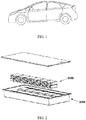
- the battery pack includes a battery module 1000 and a box body 2000, and the battery module 1000 is accommodated in the box body 2000.
- the box body 2000 includes a lower box body and an upper box cover, the lower box body and the upper box cover are connected in a sealed manner, and an accommodation cavity is formed between the lower box body and the upper box cover.
- the lower box body and the upper box cover are made of aluminum, an aluminum alloy, or other metals.
- the battery module 1000 is accommodated in the accommodation cavity of the box body 2000. There may be one or more battery modules 1000. When a plurality of battery modules 1000 are provided, the battery modules 1000 may be arranged in the length direction X or the width direction Y.
- the battery module 1000 includes a plurality of secondary batteries, and the secondary batteries are lead-acid batteries, nickel-cadmium batteries, nickel-hydrogen batteries, or lithium-ion batteries.
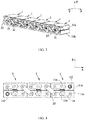
- the battery module includes a plurality of battery units 1 arranged in a horizontal direction, and each battery unit 1 includes a plurality of batteries 11 stacked in a vertical direction Z. Referring to FIG. 3 , in some embodiments, the plurality of battery units 1 of the battery module are arranged in a length direction X.
- each battery 11 of the battery module includes a first electrode terminal 111, a second electrode terminal 112, an explosion-proof piece 113, a housing 114, and an electrode assembly 115.
- the electrode assembly 115 is a core member of the battery 11 that is configured to implement charge and discharge functions.
- an electrode assembly 2 includes a first electrode plate 115a, a second electrode plate 115b, and a separator 115c separating the first electrode plate 115a from the second electrode plate 115b.
- the first electrode terminal 111 and the second electrode terminal 112 are electrically connected to the first electrode plate 115a and the second electrode plate 115b respectively.
- the first electrode plate 115a includes a first current collector and a first active substance layer coated on a surface of the first current collector.
- the second electrode plate 115b includes a second current collector and a second active substance layer coated on a surface of the second current collector.
- the first electrode plate 115a is a positive electrode plate
- the first current collector is aluminum foil
- the first active substance layer includes lithium manganate oxide, lithium iron phosphate, or a ternary material.
- the second electrode plate 115b is a negative electrode plate
- the first current collector is copper foil
- the second active material layer includes graphite or silicon.
- the housing 114 has an inner cavity to accommodate the electrode assembly 115 and an electrolyte.
- the housing 114 includes a casing 114a and a top cover 114b connected to the casing 114a.
- the casing 114a is in a hexahedral shape or another shape.
- the casing 114a has an opening, and the electrode assembly 115 may be placed into the casing 114a through the opening.
- a size of the top cover 114b fits a size of the opening of the casing 114a.
- the top cover 114b is connected to the casing 114a through welding and covers the opening of the casing 114a.
- the first electrode terminal 111 and the second electrode terminal 112 are disposed at the housing 114 and exposed out of the housing 114. In some embodiments, the first electrode terminal 111 and the second electrode terminal 112 protrude from the top cover 114b.
- the explosion-proof piece 113 is disposed at the housing 114 and located between the first electrode terminal 111 and the second electrode terminal 112.
- the top cover 114b is provided with a through vent hole, and the explosion-proof piece 113 is fixed to the top cover 114b and covers the vent hole.
- the battery module further includes a busbar assembly 2, and the busbar assembly 2 electrically connects a plurality of battery units 1 of the battery module.
- the busbar assembly 2 includes a plurality of busbars, and each busbar is connected to the electrode terminal in a manner such as welding or riveting.
- the plurality of busbars connect the plurality of batteries 11 in the battery module in series, in parallel, or in a serial and parallel connection manner to form a group.
- the plurality of batteries 11 in the battery module includes a first battery 11a and a second battery 11b stacked in the vertical direction Z.
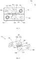
- the busbar assembly 2 includes a first busbar 21 connected to the first electrode terminal 111 of the first battery 11a and the second electrode terminal 112 of the second battery 11b.
- the first busbar 21 includes a first weak zone 211 that at least partially overlaps with the explosion-proof piece 113 of the first battery 11a.
- the plurality of battery units 1 of the battery module are arranged in a length direction X.
- the first direction is parallel to the width direction Y shown in the figure.
- a projection of the explosion-proof piece 113 of the first battery 11a at least partially overlaps with a projection of the first weak zone 211.
- the first weak zone 211 is configured to fracture when the explosion-proof piece 113 is burst, to cause an open circuit between the first battery 11a and the second battery 11b.
- the electrode assembly 115 of the first battery 11a When the electrode assembly 115 of the first battery 11a generates a large amount of gas due to overcharging, a short circuit, or the like, air pressure inside the housing 114 increases, and the explosion-proof piece 113 is burst. Because the first weak zone 211 overlaps with at least a portion of the explosion-proof piece 113, a gas at high temperature and high pressure directly strikes the first weak zone 211; and the first weak zone 211 is less strong and fractures under the impact of the gas, thereby disconnecting the electrical connection between the first battery 11a and the second battery 11b. At this point, charging and discharging of the second battery 11b has been stopped. Even if heat of the first battery 11a is transferred to the second battery 11b, the second battery 11b is not prone to thermal runaway, thereby reducing a risk of safety incidents such as a fire or an explosion and improving safety performance of the battery module.
- the explosion-proof piece 113 of the first battery 11a has an exposed zone, and the exposed zone is not covered by the first busbar 21 in the first direction. In a plane perpendicular to the first direction, a projection of the exposed zone does not overlap with a projection of the first busbar 21.
- the exposed zone is provided, so that blocking of the gas flow by the first busbar 21 can be reduced when the explosion-proof piece 113 is burst, to ensure that the gas inside the first battery 11a is smoothly expelled, thereby reducing the risk of explosion of the first battery 11a.
- the first busbar 21 further has a first through hole 212
- the first weak zone 211 includes a first portion 211a and a second portion 211b
- the first portion 211a and the second portion 211b are respectively located on two sides of the first through hole 212.
- the first through hole 212 is provided, to reduce a cross-sectional area of the first portion 211a and a cross-sectional area of the second portion 211b and reduce the strength of the first weak zone 211, thereby ensuring that the first weak zone 113 can fracture when the explosion-proof piece 113 is burst.
- the first portion 211a at least partially overlaps with the explosion-proof piece 113
- the second portion 211b at least partially overlaps with the explosion-proof piece 113.
- the explosion-proof piece 113 is burst
- the first portion 211a and the second portion 211b can fracture under the impact of the gas at the high temperature.
- the exposed zone includes a first exposed portion 113a facing toward the first through hole 212.
- the explosion-proof piece 113 When the explosion-proof piece 113 is burst, some gas can be expelled through the first through hole 212, thereby increasing a gas expulsion rate and reducing the risk of explosion of the first battery 11a.
- the exposed zone further includes a second exposed portion 113b, and the second exposed portion 113b is spaced apart from the first exposed portion 113a.
- the second exposed portion 113b is provided, so that an area of a portion of the explosion-proof piece 113 that is covered by the first busbar 21 can be reduced and the gas discharging speed is increased when the explosion-proof piece 113 is burst, thereby reducing the risk of explosion of the first battery 11a.
- the first busbar 21 is provided with a first groove.
- the first groove is provided, so that thickness of the first weak zone 211 can be decreased in this application to reduce the strength of the first weak zone 211, thereby ensuring that the first weak zone 113 can fracture when the explosion-proof piece 113 is burst.
- the first busbar 21 is provided with two first notches, and the two first notches are respectively located on two sides of the first weak zone 211. The first notches are provided, so that a thickness of the first weak zone 211 can be decreased in this application to reduce the strength of the first weak zone 211, thereby ensuring that the first weak zone 113 can fracture when the explosion-proof piece 113 is burst.
- the first busbar 21 is formed by composing a plurality of conductive materials, and the strength of the first weak zone 211 is less than strength of a portion of the first busbar 21 that is connected to the first weak zone 211, thereby ensuring that the first weak zone 113 can fracture when the explosion-proof piece 113 is burst.
- the first busbar 21 is formed by composing a plurality of conductive materials, a melting point of the first weak zone 211 is less than that of a portion of the first busbar 21 that is connected to the first weak zone 211.
- the first busbar 21 further includes a first connection portion 213 and a transition portion 215.
- the first connection portion 213 is connected to the first electrode terminal 111 of the first battery 11a, and the first weak zone 211 is connected to the first connection portion 213 and the transition portion 215.
- the first connection portion 213 is welded to the first electrode terminal 111 of the first battery 11a.
- the first connection portion 213 according to some embodiments is provided with a positioning hole, and the positioning hole helps position the first connection portion 213 during welding.
- the transition portion 215 has a buffer zone 215a; and the buffer zone 215a is configured to: flexibly deform when a distance in the horizontal direction between the first electrode terminal 111 of the first battery 11a and the second electrode terminal 112 of the second battery 11b changes; and/or flexibly deform when a distance in the vertical direction between the first electrode terminal 111 of the first battery 11a and the second electrode terminal 112 of the second battery 11b changes.
- the buffer zone 215a can flexibly deform to absorb the change in the distance between the first electrode terminal 111 of the first battery 11a and the second electrode terminal 112 of the second battery 11b, and reduce a force applied to a welding portion between the first electrode terminal 111 and the first connection portion 213, thereby reducing a risk of tearing the welding portion and ensuring the current flow capacity.
- a structure of the buffer zone 215a can be set based on requirements, provided that a force required for the deformation of the buffer zone 215a is less than a connection force between the first electrode terminal 111 and the first connection portion 213.
- the buffer zone 215a includes a plurality of arched structures, and the plurality of arched structures form a continuous waveform structure.
- the plurality of arched structures have good elasticity, and can deform to absorb the change in the distance between the first electrode terminal 111 of the first battery 11a and the second electrode terminal 112 of the second battery 11b.
- the arched structures are formed by stamping the transition portion 215.
- the buffer zone 215a includes a plurality of spaced strip structures, and at least a portion of each strip structure is bent into an arc shape.
- the arc-shaped strip structures have good elasticity, and can deform to absorb the change in the distance between the first electrode terminal 111 of the first battery 11a and the second electrode terminal 112 of the second battery 11b.
- the buffer zone 215a is bent into a waveform structure, and the waveform structure is a sinusoidal waveform, a square waveform, a triangular waveform, or a sawtooth waveform.
- the first busbar 21 is formed by combining a plurality of conductive materials, and elasticity of a material of the buffer zone 215a is better than elasticity of a material of another portion of the first busbar 21.
- the first busbar 21 further includes a second connection portion 214 and a second weak zone 216.
- the second connection portion 214 is connected to the second electrode terminal 112 of the second battery 11b.
- the second weak zone 216 at least partially overlaps with the explosion-proof piece 113 of the second battery 11b in the first direction, and the second weak zone 216 is connected to the transition portion 215 and the second connection portion 214.
- the second connection portion 214 is welded to the second electrode terminal 112 of the second battery 11b.
- the second weak zone 216 is configured to fracture when the explosion-proof piece 113 of the second battery 11b is burst, to cause an open circuit between the first battery 11a and the second battery 11b.
- the first busbar 21 is further provided with a second through hole 217.
- the second through hole 217 is provided, so that strength of the second weak zone 216 can be reduced in this application, thereby ensuring that the second weak zone 216 can fracture when the explosion-proof piece 113 is burst.
- the first busbar 21 is provided with a second groove.
- the second groove is provided, so that thickness of the second weak zone 216 can be decreased in this application to reduce the strength of the second weak zone 216, thereby ensuring that the second weak zone 216 can fracture when the explosion-proof piece 113 is burst.
- the first busbar 21 is provided with two second notches, and the two second notches are respectively located on two sides of the second weak zone 216. The second notches are provided, so that thickness of the second weak zone 216 can be decreased in this application to reduce the strength of the second weak zone 216, thereby ensuring that the second weak zone 216 can fracture when the explosion-proof piece 113 is burst.
- the first busbar 21 is formed by composing a plurality of conductive materials, and the strength of the second weak zone 216 is less than that of a portion of the first busbar 21 that is connected to the second weak zone 216, thereby ensuring that the second weak zone 216 can fracture when the explosion-proof piece 113 is burst.
- the first busbar 21 is formed by composing a plurality of conductive materials, a melting point of the second weak zone 216 is less than that of a portion of the first busbar 21 that is connected to the second weak zone 216, and when the gas at the high temperature strikes the second weak zone 216, the second weak zone 216 is heated and softened, thereby ensuring that the second weak zone 216 can fracture when the explosion-proof piece 113 is burst.
- the buffer zone 215a is provided obliquely relative to the vertical direction and the horizontal direction. In a plane perpendicular to the first direction, a projection of an exposed edge of the buffer zone 215a is provided obliquely relative to the vertical direction Z and the length direction X.
- the oblique buffer zone 215a can deform to absorb the change in the distance in the vertical direction Z and the length direction X between the first electrode terminal 111 of the first battery 11a and the second electrode terminal 112 of the second battery 11b.
- the buffer zone 215a is located between the explosion-proof piece 113 of the first battery 11a and the explosion-proof piece 113 of the second battery 11b in the vertical direction Z.
- the first weak zone 211 and the second weak zone 216 are respectively located on two sides of the buffer zone 215a in the vertical direction Z and respectively cover the explosion-proof piece 113 of the first battery 11a and the explosion-proof piece 113 of the second battery 11b.
- the first electrode terminal 111 and the second electrode terminal 112 of the first battery 11a are arranged in the horizontal direction; and the first electrode terminal 111 and the second electrode terminal 112 of the second battery 11b are arranged in the horizontal direction.
- the first electrode terminal 111 of the first battery 11a and the first electrode terminal 111 of the second battery 11b are oppositely provided in the vertical direction, and the second electrode terminal 112 of the first battery 11a and the second electrode terminal 112 of the second battery 11b are oppositely provided in the vertical direction.
- the first battery 11a and the second battery 11b are provided in the same direction, thereby facilitating stacking of the first battery 11a and the second battery 11b.
- the electrode assembly 115 is a winding structure.
- the first electrode plate 115a, the second electrode plate 115b, and the separator 115c are all strip structures.
- the first electrode plate 115a, the separator 115c, and the second electrode plate 115b are sequentially laminated, and wound at least twice to form the electrode assembly 115.
- the electrode assembly 115 is flat-shaped.
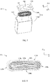
- FIG. 8 is a schematic diagram of an outline of an electrode assembly 115.
- An outer surface of the electrode assembly 115 includes two flat surfaces 115d and two narrow sides 115e, the two flat surfaces 115d are opposite each other in the vertical direction Z, and the two narrow sides 115e are opposite each other in the length direction X.
- the flat surface 115d is roughly parallel to a winding axis of the electrode assembly 115 and is a surface with the largest area.
- the flat surface 115d may be a relatively flat surface, and is not required to be an absolutely flat surface.
- At least a portion of the narrow side 115e is arc-shaped.
- the flat surface 115d is flat relative to the narrow side 115e, and an area of the flat surface 115d is greater than an area of the narrow side 115e.
- the electrode assembly 115 is a laminated structure. Specifically, the electrode assembly 115 includes a plurality of first electrode plates 115a and a plurality of second electrode plates 115b, and the plurality of first electrode plates 115a and the plurality of second electrode plates 115b are alternately laminated in the vertical direction Z.
- the separator 115c is disposed between the first electrode plate 115a and the second electrode plate 115b, and separates the first electrode plate 115a from the second electrode plate 115b.
- the first electrode plate 115a and the second electrode plate 115b are both sheet-shaped and roughly perpendicular to the vertical direction Z.
- the electrode plate In a charge and discharge process of the electrode assembly 115, the electrode plate swells in its thickness direction. In the winding electrode assembly 115, swelling force in a direction perpendicular to the flat surface 115d is the largest; and in the laminated electrode assembly 115, swelling force in a lamination direction of the first electrode plate 115a and the second electrode plate 115b is the largest. It can be seen that regardless of whether the winding structure or the laminated structure is used for the electrode assembly 115, a direction in which the electrode assembly 115 applies the largest swelling force to the casing 114b is toward the vertical direction Z. That is, in the horizontal direction, swelling force applied by the electrode assembly 115 to the housing 114b is relatively small.
- a plurality of battery units 1 are arranged in the length direction X. Therefore, even if swelling force of all electrode assemblies 115 is superimposed in the length direction X, no excessive resultant force is generated, thereby reducing a risk of crushing the battery 11.
- a size of the battery module 1000 in the horizontal direction is greater than a size of the battery module 1000 in the vertical direction Z.
- the size of the battery module 1000 in the length direction X is greater than the size of the battery module 1000 in the vertical direction Z.
- a quantity of batteries 11 of each battery unit 1 is decreased to reduce swelling force of each battery unit 1 in the vertical direction Z.
- the battery module 1000 may have a relatively large size in the length direction X. That is, there may be a relatively large quantity of battery units 11.
- the battery module 1 preferably has a relatively small size in the vertical direction Z.
- the battery module further includes two end plates (not shown in the figure) and a tie (not shown in the figure).
- the two end plates are respectively provided at two ends of the plurality of battery units 1 in the length direction X, and the tie surrounds peripheries of the plurality of battery units 1 and the two end plates, thereby fixing the plurality of battery units 1.
- the end plate may be made of a metal material such as aluminum or an aluminum alloy, or may be made of an insulation material.
- the busbar assembly 2 further includes a second busbar 22, and the second busbar 22 connects a first electrode terminal 111 of a battery 11 of a battery unit 1 and a first electrode terminal 111 of a battery 11 of another battery unit 1.
- the second busbar 22 is provided obliquely relative to the vertical direction Z and the length direction X.
- first busbars 21 and a plurality of second busbars 22 there are a plurality of first busbars 21 and a plurality of second busbars 22, and the plurality of first busbars 21 and the plurality of second busbars 22 electrically connect all batteries 11 of the battery module.
- the busbar assembly 2 further includes two output electrode plates 23, and the two output electrode plates 23 are respectively connected to an electrode terminal serving as a total positive output and an electrode terminal serving as a total negative output in the battery module.
Landscapes
- Chemical & Material Sciences (AREA)
- Chemical Kinetics & Catalysis (AREA)
- Electrochemistry (AREA)
- General Chemical & Material Sciences (AREA)
- Engineering & Computer Science (AREA)
- Manufacturing & Machinery (AREA)
- Battery Mounting, Suspending (AREA)
- Connection Of Batteries Or Terminals (AREA)
- Gas Exhaust Devices For Batteries (AREA)
- Aviation & Aerospace Engineering (AREA)
Priority Applications (1)
| Application Number | Priority Date | Filing Date | Title |
|---|---|---|---|
| HUE20922493A HUE061537T2 (hu) | 2020-04-03 | 2020-04-03 | Akkumulátor modul, akkumulátor csomag, és az akkumulátort tápegységként használó berendezés |
Applications Claiming Priority (1)
| Application Number | Priority Date | Filing Date | Title |
|---|---|---|---|
| PCT/CN2020/083248 WO2021196169A1 (fr) | 2020-04-03 | 2020-04-03 | Module de batterie, bloc-batterie et appareil utilisant une batterie comme source d'alimentation |
Publications (3)
| Publication Number | Publication Date |
|---|---|
| EP3923409A1 true EP3923409A1 (fr) | 2021-12-15 |
| EP3923409A4 EP3923409A4 (fr) | 2022-04-27 |
| EP3923409B1 EP3923409B1 (fr) | 2023-03-15 |
Family
ID=77927339
Family Applications (1)
| Application Number | Title | Priority Date | Filing Date |
|---|---|---|---|
| EP20922493.0A Active EP3923409B1 (fr) | 2020-04-03 | 2020-04-03 | Module de batterie, bloc-batterie et appareil utilisant une batterie comme source d'alimentation |
Country Status (7)
| Country | Link |
|---|---|
| US (1) | US12002994B2 (fr) |
| EP (1) | EP3923409B1 (fr) |
| JP (1) | JP7186926B2 (fr) |
| KR (1) | KR102519837B1 (fr) |
| CN (1) | CN114467225B (fr) |
| HU (1) | HUE061537T2 (fr) |
| WO (1) | WO2021196169A1 (fr) |
Families Citing this family (10)
| Publication number | Priority date | Publication date | Assignee | Title |
|---|---|---|---|---|
| KR102545057B1 (ko) * | 2020-11-12 | 2023-06-20 | 주식회사 성우하이텍 | 배터리의 단자 연결 유닛 |
| JP7548050B2 (ja) * | 2021-02-19 | 2024-09-10 | トヨタ自動車株式会社 | 組電池 |
| KR102953335B1 (ko) * | 2022-10-26 | 2026-04-15 | 주식회사 엘지에너지솔루션 | 열폭주 전이를 지연시킬 수 있는 인터 모듈 버스바 및 이를 포함하는 전지 팩 |
| CN218939947U (zh) * | 2022-11-21 | 2023-04-28 | 宁德时代新能源科技股份有限公司 | 电池及用电设备 |
| CN115764176A (zh) * | 2022-11-30 | 2023-03-07 | 厦门海辰储能科技股份有限公司 | 汇流单元、电池模组及用电设备 |
| KR20240148594A (ko) * | 2023-04-04 | 2024-10-11 | 삼성에스디아이 주식회사 | 배터리 모듈 |
| US12597683B2 (en) | 2023-06-16 | 2026-04-07 | Lg Energy Solution, Ltd. | Current collector, battery cell, battery pack, and vehicle including the same |
| DE102023121341A1 (de) * | 2023-08-10 | 2025-02-13 | Bayerische Motoren Werke Aktiengesellschaft | Entgasungsstutzen für eine Entgasungsvorrichtung aufweisende Batteriezelle einer Energiespeichervorrichtung eines Kraftfahrzeugs, Entgasungsstutzenverbund, Energiespeichervorrichtung und Kraftfahrzeugs |
| KR20250036473A (ko) * | 2023-09-07 | 2025-03-14 | 에스케이온 주식회사 | 버스바 및 이를 포함하는 배터리 모듈 |
| WO2025236466A1 (fr) * | 2024-05-14 | 2025-11-20 | 惠州亿纬锂能股份有限公司 | Barre omnibus, module de batterie et bloc-batterie |
Family Cites Families (20)
| Publication number | Priority date | Publication date | Assignee | Title |
|---|---|---|---|---|
| JPH0794166A (ja) * | 1993-09-28 | 1995-04-07 | Matsushita Electric Ind Co Ltd | 鉛蓄電池 |
| JP2009087720A (ja) | 2007-09-28 | 2009-04-23 | Toshiba Corp | 電池パック |
| WO2011047067A2 (fr) | 2009-10-14 | 2011-04-21 | Johnson Controls - Saft Advanced Power Solutions Llc | Système de cellules prismatiques à éléments de gestion thermique |
| JP5454364B2 (ja) | 2010-06-02 | 2014-03-26 | トヨタ自動車株式会社 | 組電池及び車両 |
| KR101433199B1 (ko) * | 2011-11-28 | 2014-08-26 | 주식회사 엘지화학 | 배터리 모듈 및 배터리 모듈에 적용되는 버스 바 |
| CN204706600U (zh) * | 2015-05-27 | 2015-10-14 | 山东梅拉德能源动力科技有限公司 | 一种电池成组用连接片 |
| CN204793019U (zh) * | 2015-06-26 | 2015-11-18 | 广东新凌嘉新能源股份有限公司 | 锂电池模组 |
| JP6636775B2 (ja) * | 2015-11-04 | 2020-01-29 | 株式会社エンビジョンAescジャパン | 電池パック |
| CN205882057U (zh) * | 2016-04-08 | 2017-01-11 | 深圳市沃特玛电池有限公司 | 一种二次电池结构 |
| JP6814389B2 (ja) * | 2017-04-10 | 2021-01-20 | トヨタ自動車株式会社 | 組電池 |
| KR102096983B1 (ko) * | 2017-09-08 | 2020-04-03 | 주식회사 엘지화학 | 벤팅 가스를 이용하여 커넥터를 파단시키는 구조를 갖는 배터리 모듈 |
| CN109728208B (zh) * | 2017-10-27 | 2021-09-14 | 宁德时代新能源科技股份有限公司 | 二次电池的顶盖组件、二次电池以及电池模组 |
| JP2019220433A (ja) | 2018-06-22 | 2019-12-26 | 株式会社豊田自動織機 | 蓄電装置 |
| EP3817087B1 (fr) | 2018-06-26 | 2024-07-03 | SANYO Electric Co., Ltd. | Système de batterie, et véhicule électrique et dispositif de stockage électrique comprenant un système de batterie |
| KR102598669B1 (ko) | 2018-09-11 | 2023-11-06 | 에스케이온 주식회사 | 버스 바 및 이를 구비하는 배터리 팩 |
| CN209104250U (zh) | 2018-11-19 | 2019-07-12 | 宁德时代新能源科技股份有限公司 | 电池模组 |
| CN209447876U (zh) * | 2018-12-30 | 2019-09-27 | 宁德时代新能源科技股份有限公司 | 一种电池模组 |
| CN209730034U (zh) * | 2019-01-18 | 2019-12-03 | 宁德时代新能源科技股份有限公司 | 一种电池模块 |
| CN209709060U (zh) * | 2019-05-29 | 2019-11-29 | 宁德时代新能源科技股份有限公司 | 电池模块和电池包 |
| JP7548050B2 (ja) * | 2021-02-19 | 2024-09-10 | トヨタ自動車株式会社 | 組電池 |
-
2020
- 2020-04-03 WO PCT/CN2020/083248 patent/WO2021196169A1/fr not_active Ceased
- 2020-04-03 KR KR1020227016761A patent/KR102519837B1/ko active Active
- 2020-04-03 EP EP20922493.0A patent/EP3923409B1/fr active Active
- 2020-04-03 JP JP2022530274A patent/JP7186926B2/ja active Active
- 2020-04-03 CN CN202080068519.7A patent/CN114467225B/zh active Active
- 2020-04-03 HU HUE20922493A patent/HUE061537T2/hu unknown
-
2021
- 2021-09-29 US US17/488,437 patent/US12002994B2/en active Active
Also Published As
| Publication number | Publication date |
|---|---|
| CN114467225A (zh) | 2022-05-10 |
| JP2022549025A (ja) | 2022-11-22 |
| WO2021196169A1 (fr) | 2021-10-07 |
| US12002994B2 (en) | 2024-06-04 |
| HUE061537T2 (hu) | 2023-07-28 |
| EP3923409A4 (fr) | 2022-04-27 |
| CN114467225B (zh) | 2023-12-15 |
| KR20220083799A (ko) | 2022-06-20 |
| EP3923409B1 (fr) | 2023-03-15 |
| JP7186926B2 (ja) | 2022-12-09 |
| KR102519837B1 (ko) | 2023-04-10 |
| US20220021082A1 (en) | 2022-01-20 |
Similar Documents
| Publication | Publication Date | Title |
|---|---|---|
| US12002994B2 (en) | Battery module, battery pack, and battery-powered apparatus | |
| EP3678208B1 (fr) | Module de batterie, bloc batterie et véhicule | |
| US11936024B2 (en) | Battery pack, method for producing battery pack and vehicle | |
| US12136694B2 (en) | Battery, electric apparatus, and cell installation method | |
| EP4485655B1 (fr) | Batterie et dispositif électrique | |
| CN217788566U (zh) | 电池单体、电池及用电装置 | |
| US11862776B2 (en) | Battery, power consumption device, and method and device for producing battery | |
| EP4266464A1 (fr) | Batterie, dispositif électrique, procédé et dispositif de préparation de batterie | |
| EP4258445A1 (fr) | Batterie, dispositif électrique, et procédé et dispositif de préparation de batterie | |
| WO2023133748A1 (fr) | Module de batterie, batterie, dispositif électrique, et procédé et dispositif de préparation de batterie | |
| JP4348492B2 (ja) | 非水系二次電池 | |
| WO2024114131A1 (fr) | Batterie et appareil électrique | |
| CN219144431U (zh) | 电极组件、电池单体、电池及用电装置 | |
| EP4261997A1 (fr) | Batterie, dispositif électrique et procédé et dispositif de préparation de batterie | |
| EP4354574A1 (fr) | Batterie, dispositif électrique, et procédé et dispositif de préparation de batterie | |
| US20240243366A1 (en) | Electrode assembly and preparation method therefor, battery cell, battery, and power consuming apparatus | |
| EP4258437B1 (fr) | Batterie et dispositif électrique | |
| CN217768426U (zh) | 电极组件、电池单体、电池以及用电装置 | |
| EP4421890A1 (fr) | Feuille d'électrode, ensemble électrode, élément de batterie, batterie et dispositif électrique | |
| EP4037087A1 (fr) | Dispositif équipotentiel, structure équipotentielle, batterie et appareil consommateur d'énergie | |
| CN223487094U (zh) | 电池单体、电池装置及用电装置 | |
| CN224123495U (zh) | 电池单体、电池装置及用电设备 | |
| CN121416637A (zh) | 一种电池单体、电池及用电装置 |
Legal Events
| Date | Code | Title | Description |
|---|---|---|---|
| STAA | Information on the status of an ep patent application or granted ep patent |
Free format text: STATUS: UNKNOWN |
|
| STAA | Information on the status of an ep patent application or granted ep patent |
Free format text: STATUS: THE INTERNATIONAL PUBLICATION HAS BEEN MADE |
|
| PUAI | Public reference made under article 153(3) epc to a published international application that has entered the european phase |
Free format text: ORIGINAL CODE: 0009012 |
|
| STAA | Information on the status of an ep patent application or granted ep patent |
Free format text: STATUS: REQUEST FOR EXAMINATION WAS MADE |
|
| 17P | Request for examination filed |
Effective date: 20210909 |
|
| AK | Designated contracting states |
Kind code of ref document: A1 Designated state(s): AL AT BE BG CH CY CZ DE DK EE ES FI FR GB GR HR HU IE IS IT LI LT LU LV MC MK MT NL NO PL PT RO RS SE SI SK SM TR |
|
| A4 | Supplementary search report drawn up and despatched |
Effective date: 20220324 |
|
| RIC1 | Information provided on ipc code assigned before grant |
Ipc: H01M 50/50 20210101ALI20220319BHEP Ipc: H01M 50/572 20210101AFI20220319BHEP |
|
| STAA | Information on the status of an ep patent application or granted ep patent |
Free format text: STATUS: EXAMINATION IS IN PROGRESS |
|
| 17Q | First examination report despatched |
Effective date: 20220919 |
|
| GRAP | Despatch of communication of intention to grant a patent |
Free format text: ORIGINAL CODE: EPIDOSNIGR1 |
|
| STAA | Information on the status of an ep patent application or granted ep patent |
Free format text: STATUS: GRANT OF PATENT IS INTENDED |
|
| GRAS | Grant fee paid |
Free format text: ORIGINAL CODE: EPIDOSNIGR3 |
|
| DAV | Request for validation of the european patent (deleted) | ||
| DAX | Request for extension of the european patent (deleted) | ||
| INTG | Intention to grant announced |
Effective date: 20230112 |
|
| GRAA | (expected) grant |
Free format text: ORIGINAL CODE: 0009210 |
|
| STAA | Information on the status of an ep patent application or granted ep patent |
Free format text: STATUS: THE PATENT HAS BEEN GRANTED |
|
| AK | Designated contracting states |
Kind code of ref document: B1 Designated state(s): AL AT BE BG CH CY CZ DE DK EE ES FI FR GB GR HR HU IE IS IT LI LT LU LV MC MK MT NL NO PL PT RO RS SE SI SK SM TR |
|
| REG | Reference to a national code |
Ref country code: CH Ref legal event code: EP Ref country code: GB Ref legal event code: FG4D |
|
| REG | Reference to a national code |
Ref country code: DE Ref legal event code: R096 Ref document number: 602020008933 Country of ref document: DE |
|
| REG | Reference to a national code |
Ref country code: IE Ref legal event code: FG4D |
|
| REG | Reference to a national code |
Ref country code: AT Ref legal event code: REF Ref document number: 1554522 Country of ref document: AT Kind code of ref document: T Effective date: 20230415 |
|
| REG | Reference to a national code |
Ref country code: SE Ref legal event code: TRGR |
|
| P01 | Opt-out of the competence of the unified patent court (upc) registered |
Effective date: 20230516 |
|
| REG | Reference to a national code |
Ref country code: LT Ref legal event code: MG9D |
|
| REG | Reference to a national code |
Ref country code: NL Ref legal event code: MP Effective date: 20230315 |
|
| REG | Reference to a national code |
Ref country code: HU Ref legal event code: AG4A Ref document number: E061537 Country of ref document: HU |
|
| PG25 | Lapsed in a contracting state [announced via postgrant information from national office to epo] |
Ref country code: RS Free format text: LAPSE BECAUSE OF FAILURE TO SUBMIT A TRANSLATION OF THE DESCRIPTION OR TO PAY THE FEE WITHIN THE PRESCRIBED TIME-LIMIT Effective date: 20230315 Ref country code: NO Free format text: LAPSE BECAUSE OF FAILURE TO SUBMIT A TRANSLATION OF THE DESCRIPTION OR TO PAY THE FEE WITHIN THE PRESCRIBED TIME-LIMIT Effective date: 20230615 Ref country code: LV Free format text: LAPSE BECAUSE OF FAILURE TO SUBMIT A TRANSLATION OF THE DESCRIPTION OR TO PAY THE FEE WITHIN THE PRESCRIBED TIME-LIMIT Effective date: 20230315 Ref country code: LT Free format text: LAPSE BECAUSE OF FAILURE TO SUBMIT A TRANSLATION OF THE DESCRIPTION OR TO PAY THE FEE WITHIN THE PRESCRIBED TIME-LIMIT Effective date: 20230315 Ref country code: HR Free format text: LAPSE BECAUSE OF FAILURE TO SUBMIT A TRANSLATION OF THE DESCRIPTION OR TO PAY THE FEE WITHIN THE PRESCRIBED TIME-LIMIT Effective date: 20230315 |
|
| REG | Reference to a national code |
Ref country code: AT Ref legal event code: MK05 Ref document number: 1554522 Country of ref document: AT Kind code of ref document: T Effective date: 20230315 |
|
| PG25 | Lapsed in a contracting state [announced via postgrant information from national office to epo] |
Ref country code: NL Free format text: LAPSE BECAUSE OF FAILURE TO SUBMIT A TRANSLATION OF THE DESCRIPTION OR TO PAY THE FEE WITHIN THE PRESCRIBED TIME-LIMIT Effective date: 20230315 Ref country code: GR Free format text: LAPSE BECAUSE OF FAILURE TO SUBMIT A TRANSLATION OF THE DESCRIPTION OR TO PAY THE FEE WITHIN THE PRESCRIBED TIME-LIMIT Effective date: 20230616 Ref country code: FI Free format text: LAPSE BECAUSE OF FAILURE TO SUBMIT A TRANSLATION OF THE DESCRIPTION OR TO PAY THE FEE WITHIN THE PRESCRIBED TIME-LIMIT Effective date: 20230315 |
|
| PG25 | Lapsed in a contracting state [announced via postgrant information from national office to epo] |
Ref country code: SM Free format text: LAPSE BECAUSE OF FAILURE TO SUBMIT A TRANSLATION OF THE DESCRIPTION OR TO PAY THE FEE WITHIN THE PRESCRIBED TIME-LIMIT Effective date: 20230315 Ref country code: RO Free format text: LAPSE BECAUSE OF FAILURE TO SUBMIT A TRANSLATION OF THE DESCRIPTION OR TO PAY THE FEE WITHIN THE PRESCRIBED TIME-LIMIT Effective date: 20230315 Ref country code: PT Free format text: LAPSE BECAUSE OF FAILURE TO SUBMIT A TRANSLATION OF THE DESCRIPTION OR TO PAY THE FEE WITHIN THE PRESCRIBED TIME-LIMIT Effective date: 20230717 Ref country code: ES Free format text: LAPSE BECAUSE OF FAILURE TO SUBMIT A TRANSLATION OF THE DESCRIPTION OR TO PAY THE FEE WITHIN THE PRESCRIBED TIME-LIMIT Effective date: 20230315 Ref country code: EE Free format text: LAPSE BECAUSE OF FAILURE TO SUBMIT A TRANSLATION OF THE DESCRIPTION OR TO PAY THE FEE WITHIN THE PRESCRIBED TIME-LIMIT Effective date: 20230315 Ref country code: CZ Free format text: LAPSE BECAUSE OF FAILURE TO SUBMIT A TRANSLATION OF THE DESCRIPTION OR TO PAY THE FEE WITHIN THE PRESCRIBED TIME-LIMIT Effective date: 20230315 Ref country code: AT Free format text: LAPSE BECAUSE OF FAILURE TO SUBMIT A TRANSLATION OF THE DESCRIPTION OR TO PAY THE FEE WITHIN THE PRESCRIBED TIME-LIMIT Effective date: 20230315 |
|
| PG25 | Lapsed in a contracting state [announced via postgrant information from national office to epo] |
Ref country code: SK Free format text: LAPSE BECAUSE OF FAILURE TO SUBMIT A TRANSLATION OF THE DESCRIPTION OR TO PAY THE FEE WITHIN THE PRESCRIBED TIME-LIMIT Effective date: 20230315 Ref country code: PL Free format text: LAPSE BECAUSE OF FAILURE TO SUBMIT A TRANSLATION OF THE DESCRIPTION OR TO PAY THE FEE WITHIN THE PRESCRIBED TIME-LIMIT Effective date: 20230315 Ref country code: IS Free format text: LAPSE BECAUSE OF FAILURE TO SUBMIT A TRANSLATION OF THE DESCRIPTION OR TO PAY THE FEE WITHIN THE PRESCRIBED TIME-LIMIT Effective date: 20230715 |
|
| REG | Reference to a national code |
Ref country code: CH Ref legal event code: PL |
|
| REG | Reference to a national code |
Ref country code: DE Ref legal event code: R097 Ref document number: 602020008933 Country of ref document: DE |
|
| PG25 | Lapsed in a contracting state [announced via postgrant information from national office to epo] |
Ref country code: LU Free format text: LAPSE BECAUSE OF NON-PAYMENT OF DUE FEES Effective date: 20230403 |
|
| REG | Reference to a national code |
Ref country code: BE Ref legal event code: MM Effective date: 20230430 |
|
| PG25 | Lapsed in a contracting state [announced via postgrant information from national office to epo] |
Ref country code: MC Free format text: LAPSE BECAUSE OF FAILURE TO SUBMIT A TRANSLATION OF THE DESCRIPTION OR TO PAY THE FEE WITHIN THE PRESCRIBED TIME-LIMIT Effective date: 20230315 |
|
| PLBE | No opposition filed within time limit |
Free format text: ORIGINAL CODE: 0009261 |
|
| STAA | Information on the status of an ep patent application or granted ep patent |
Free format text: STATUS: NO OPPOSITION FILED WITHIN TIME LIMIT |
|
| PG25 | Lapsed in a contracting state [announced via postgrant information from national office to epo] |
Ref country code: SI Free format text: LAPSE BECAUSE OF FAILURE TO SUBMIT A TRANSLATION OF THE DESCRIPTION OR TO PAY THE FEE WITHIN THE PRESCRIBED TIME-LIMIT Effective date: 20230315 Ref country code: MC Free format text: LAPSE BECAUSE OF FAILURE TO SUBMIT A TRANSLATION OF THE DESCRIPTION OR TO PAY THE FEE WITHIN THE PRESCRIBED TIME-LIMIT Effective date: 20230315 Ref country code: LI Free format text: LAPSE BECAUSE OF NON-PAYMENT OF DUE FEES Effective date: 20230430 Ref country code: DK Free format text: LAPSE BECAUSE OF FAILURE TO SUBMIT A TRANSLATION OF THE DESCRIPTION OR TO PAY THE FEE WITHIN THE PRESCRIBED TIME-LIMIT Effective date: 20230315 Ref country code: CH Free format text: LAPSE BECAUSE OF NON-PAYMENT OF DUE FEES Effective date: 20230430 |
|
| REG | Reference to a national code |
Ref country code: IE Ref legal event code: MM4A |
|
| 26N | No opposition filed |
Effective date: 20231218 |
|
| PG25 | Lapsed in a contracting state [announced via postgrant information from national office to epo] |
Ref country code: BE Free format text: LAPSE BECAUSE OF NON-PAYMENT OF DUE FEES Effective date: 20230430 |
|
| PG25 | Lapsed in a contracting state [announced via postgrant information from national office to epo] |
Ref country code: IE Free format text: LAPSE BECAUSE OF NON-PAYMENT OF DUE FEES Effective date: 20230403 |
|
| PG25 | Lapsed in a contracting state [announced via postgrant information from national office to epo] |
Ref country code: IE Free format text: LAPSE BECAUSE OF NON-PAYMENT OF DUE FEES Effective date: 20230403 |
|
| PG25 | Lapsed in a contracting state [announced via postgrant information from national office to epo] |
Ref country code: IT Free format text: LAPSE BECAUSE OF FAILURE TO SUBMIT A TRANSLATION OF THE DESCRIPTION OR TO PAY THE FEE WITHIN THE PRESCRIBED TIME-LIMIT Effective date: 20230315 |
|
| REG | Reference to a national code |
Ref country code: DE Ref legal event code: R081 Ref document number: 602020008933 Country of ref document: DE Owner name: CONTEMPORARY AMPEREX TECHNOLOGY (HONG KONG) LI, HK Free format text: FORMER OWNER: CONTEMPORARY AMPEREX TECHNOLOGY CO., LIMITED, NINGDE, FUJIAN, CN |
|
| REG | Reference to a national code |
Ref country code: GB Ref legal event code: 732E Free format text: REGISTERED BETWEEN 20240822 AND 20240828 |
|
| REG | Reference to a national code |
Ref country code: HU Ref legal event code: GB9C Owner name: CONTEMPORARY AMPEREX TECHNOLOGY (HONG KONG) LIMITED, HK Free format text: FORMER OWNER(S): CONTEMPORARY AMPEREX TECHNOLOGY CO., LIMITED, CN Ref country code: HU Ref legal event code: FH1C Free format text: FORMER REPRESENTATIVE(S): SBGK SZABADALMI UEGYVIVOEI IRODA, HU Representative=s name: DANUBIA SZABADALMI ES JOGI IRODA KFT., HU |
|
| PG25 | Lapsed in a contracting state [announced via postgrant information from national office to epo] |
Ref country code: BG Free format text: LAPSE BECAUSE OF FAILURE TO SUBMIT A TRANSLATION OF THE DESCRIPTION OR TO PAY THE FEE WITHIN THE PRESCRIBED TIME-LIMIT Effective date: 20230315 |
|
| PG25 | Lapsed in a contracting state [announced via postgrant information from national office to epo] |
Ref country code: BG Free format text: LAPSE BECAUSE OF FAILURE TO SUBMIT A TRANSLATION OF THE DESCRIPTION OR TO PAY THE FEE WITHIN THE PRESCRIBED TIME-LIMIT Effective date: 20230315 |
|
| PGFP | Annual fee paid to national office [announced via postgrant information from national office to epo] |
Ref country code: DE Payment date: 20250204 Year of fee payment: 6 |
|
| PGFP | Annual fee paid to national office [announced via postgrant information from national office to epo] |
Ref country code: HU Payment date: 20250224 Year of fee payment: 6 |
|
| PG25 | Lapsed in a contracting state [announced via postgrant information from national office to epo] |
Ref country code: CY Free format text: LAPSE BECAUSE OF FAILURE TO SUBMIT A TRANSLATION OF THE DESCRIPTION OR TO PAY THE FEE WITHIN THE PRESCRIBED TIME-LIMIT; INVALID AB INITIO Effective date: 20200403 |
|
| PG25 | Lapsed in a contracting state [announced via postgrant information from national office to epo] |
Ref country code: TR Free format text: LAPSE BECAUSE OF FAILURE TO SUBMIT A TRANSLATION OF THE DESCRIPTION OR TO PAY THE FEE WITHIN THE PRESCRIBED TIME-LIMIT Effective date: 20230315 |
|
| PGFP | Annual fee paid to national office [announced via postgrant information from national office to epo] |
Ref country code: SE Payment date: 20260227 Year of fee payment: 7 |
|
| PGFP | Annual fee paid to national office [announced via postgrant information from national office to epo] |
Ref country code: GB Payment date: 20260223 Year of fee payment: 7 |
|
| PGFP | Annual fee paid to national office [announced via postgrant information from national office to epo] |
Ref country code: FR Payment date: 20260223 Year of fee payment: 7 |