EP3923478A1 - Capteur de proximité et procédé d'utilisation - Google Patents
Capteur de proximité et procédé d'utilisation Download PDFInfo
- Publication number
- EP3923478A1 EP3923478A1 EP21178874.0A EP21178874A EP3923478A1 EP 3923478 A1 EP3923478 A1 EP 3923478A1 EP 21178874 A EP21178874 A EP 21178874A EP 3923478 A1 EP3923478 A1 EP 3923478A1
- Authority
- EP
- European Patent Office
- Prior art keywords
- instance
- sensor
- voltage
- reference resistor
- inductor
- Prior art date
- Legal status (The legal status is an assumption and is not a legal conclusion. Google has not performed a legal analysis and makes no representation as to the accuracy of the status listed.)
- Pending
Links
Images

Classifications
-
- H—ELECTRICITY
- H03—ELECTRONIC CIRCUITRY
- H03K—PULSE TECHNIQUE
- H03K17/00—Electronic switching or gating, i.e. not by contact-making and –breaking
- H03K17/94—Electronic switching or gating, i.e. not by contact-making and –breaking characterised by the way in which the control signals are generated
- H03K17/945—Proximity switches
- H03K17/95—Proximity switches using a magnetic detector
- H03K17/952—Proximity switches using a magnetic detector using inductive coils
-
- G—PHYSICS
- G01—MEASURING; TESTING
- G01D—MEASURING NOT SPECIALLY ADAPTED FOR A SPECIFIC VARIABLE; ARRANGEMENTS FOR MEASURING TWO OR MORE VARIABLES NOT COVERED IN A SINGLE OTHER SUBCLASS; TARIFF METERING APPARATUS; MEASURING OR TESTING NOT OTHERWISE PROVIDED FOR
- G01D5/00—Mechanical means for transferring the output of a sensing member; Means for converting the output of a sensing member to another variable where the form or nature of the sensing member does not constrain the means for converting; Transducers not specially adapted for a specific variable
- G01D5/12—Mechanical means for transferring the output of a sensing member; Means for converting the output of a sensing member to another variable where the form or nature of the sensing member does not constrain the means for converting; Transducers not specially adapted for a specific variable using electric or magnetic means
- G01D5/14—Mechanical means for transferring the output of a sensing member; Means for converting the output of a sensing member to another variable where the form or nature of the sensing member does not constrain the means for converting; Transducers not specially adapted for a specific variable using electric or magnetic means influencing the magnitude of a current or voltage
- G01D5/20—Mechanical means for transferring the output of a sensing member; Means for converting the output of a sensing member to another variable where the form or nature of the sensing member does not constrain the means for converting; Transducers not specially adapted for a specific variable using electric or magnetic means influencing the magnitude of a current or voltage by varying inductance, e.g. by a movable armature
-
- H—ELECTRICITY
- H03—ELECTRONIC CIRCUITRY
- H03K—PULSE TECHNIQUE
- H03K17/00—Electronic switching or gating, i.e. not by contact-making and –breaking
- H03K17/94—Electronic switching or gating, i.e. not by contact-making and –breaking characterised by the way in which the control signals are generated
- H03K17/945—Proximity switches
- H03K17/95—Proximity switches using a magnetic detector
- H03K17/9502—Measures for increasing reliability
-
- H—ELECTRICITY
- H03—ELECTRONIC CIRCUITRY
- H03K—PULSE TECHNIQUE
- H03K2217/00—Indexing scheme related to electronic switching or gating, i.e. not by contact-making or -breaking covered by H03K17/00
- H03K2217/94—Indexing scheme related to electronic switching or gating, i.e. not by contact-making or -breaking covered by H03K17/00 characterised by the way in which the control signal is generated
- H03K2217/945—Proximity switches
- H03K2217/95—Proximity switches using a magnetic detector
- H03K2217/952—Detection of ferromagnetic and non-magnetic conductive targets
Definitions
- the present disclosure relates to a proximity sensor, and more particularly to a proximity sensor configured to sense the position of a ferromagnetic target.
- Proximity sensing devices are devices that produce an output based upon a distance between two or more sensors or objects.
- Proximity sensors typically contain electrical circuits having an electrical, mechanical, or optical distance sensing portion.
- Electromechanical sensors are often used to establish contact between two objects, such as an end switch, and electrical sensors are frequently used when a distance measurement is desired.
- Electrical proximity sensors commonly include inductance sensors, which rely on unique electrical properties of inductance circuits to detect the proximity of a target object.
- Proximity sensors are prevalent in several industries, such as process management, automotive, and aviation. Their applications span a large range from traffic control to linkage actuation control.
- proximity sensing devices are an integral and indispensable component of a modem aircraft. Knowledge that a moving surface has reached a particular location in its travel can promote proper and safe operation of various aircraft systems.
- a variety of proximity sensors are known, but as the needs of modern aircraft develop the sizes, weights, and speeds of the typical proximity are not enough.
- the conventional proximity methods and systems have generally been considered satisfactory for their intended purpose. However, there is still a need in the art for proximity sensors having improved speeds and reliability. There also remains a need in the art for such systems and components that are economically viable.
- the present disclosure may provide a solution for at least one of these remaining challenges.
- a method of measuring target proximity includes transmitting a magnetic field signal by a controller of a proximity sensor at a target, measuring impedance of an inductor of a proximity sensor, calculating a relative position of the target in relation to a sensor face, and providing a near/far output status of the target at a predetermined rate of below 4 milliseconds.
- the voltage can be measured through a reference resistor, where calculating a relative position includes a ratio of a change in DC voltage across the inductor at two distinct times and a change in DC voltage across the reference resistor.
- Calculating the inductance of the sensor which is then used to infer the target position can be based on the equation Rref[(Vsensor,tl *t2) - (Vsensor,t2 *t1)]/( Vref,t2 - Vref,t1) where Rref is the resistance of the reference resistor, Vsensor,t1 is voltage across the inductor at a first instance, Vsensor,t2 is voltage across the inductor at a second instance, t1 is a first instance, t2 is a second instance, Vref,t2 is a voltage across the reference resistor at a second instance, and Vref,t1 is a voltage across the reference resistor at a first instance.
- the first instance of the sensor and the second instance of the inductor can be the same as the
- the current sent through the reference resistor can include trapezoidal amperage, wherein the current sent through the reference resistor is increased from a first instance to a second instance and decreased thereafter.
- a proximity sensor configured to produce the method described above includes a sensor face, sensor electronics within the sensor face configured to transmit a magnetic field signal at a target, wherein the sensor electronics include at least one reference resistor and at least one inductor sensor, and a controller configured to control the magnetic field signal.
- the controller can be configured to calculate a relative position of a target using a ratio of a change in DC voltage across the inductor at two distinct times and a change in DC voltage across the reference resistor.
- Fig. 1 a partial view of an exemplary embodiment of a proximity sensor in accordance with the invention is shown in Fig. 1 and is designated generally by reference character 100.
- the methods and systems of the invention can be used to decrease the size of typical proximity sensor and to increase reliability.
- a method of measuring target 10 proximity includes transmitting a magnetic field signal by a controller 103 of a proximity sensor at a target 10, measuring impedance of an inductor 104 of a proximity sensor 105, calculating a relative position of the target 10 in relation to a sensor face 107, and providing a near/far output status of the target at a predetermined rate of below 4 milliseconds.
- the methods described below are used to remotely sense the position of a ferromagnetic target by the utilizing the inductance measurement of a proximity sensor located in the region of the target.
- Measurement Electronics are co-located within the proximity sensor to eliminate the need to pass analog sensor measurements over long cable lengths.
- Fig. 1 shows the electronics of a proximity sensor 100 configured to transmit a magnetic field signal at a target 10.
- the sensor includes at least one reference resistor 102 placed in parallel with at least one inductor sensor 104.
- the controller 103 is also configured to calculate a relative position of a target using a ratio of a change in DC voltage across the inductor 104 at two distinct times and a change in DC voltage across the reference resistor 102.
- the inductor 104 and the reference resistor 102 are toggled by the switch system 109 also located within the proximity sensor 100.
- Measuring target proximity includes transmitting a current signal by the controller 103, measuring impedance of the inductor 104, calculating a relative position of the target in relation to a sensor face, and providing a near/far output status of the target at a predetermined rate. Voltage is then measured through the reference resistor 102.
- the reference resistor 102 is a separate precision resistor that is switched in by the switch system 109 or multiplexer and receives the same trapezoidal current that is used to drive the inductor 104.
- calculating a relative position includes a ratio of a change in DC voltage across the inductor 104 at two distinct times and a change in DC voltage across the reference resistor 102.
- Calculating the inductance of the sensor which is then used to infer the target position is based on the equation Rref[(Vsensor,tl *t2) - (Vsensor,t2 *t1)]/( Vref,t2 - Vref,t1)
- Rref is the resistance of the reference resistor 102
- Vsensor,t1 is voltage across the inductor 104 at a first instance
- Vsensor,t2 is voltage across the inductor 104 at a second instance
- t1 is a first instance
- t2 is a second instance
- Vref,t2 is a voltage across the reference resistor 102 at a second instance
- Vref,t1 is a voltage across the reference resistor 102 at a first instance.
- the first instance of the sensor and the second instance of the inductor 104 can be the same as the first instance of the resistor 102 and the second instance of the resistor 102.
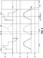
- the current sent through the reference resistor 102 includes trapezoidal amperage as shown in Fig. 2 , wherein the current sent through the reference resistor 102 is increased from a first instance to a second instance and decreased thereafter.
- the trapezoidal current allows the signal conditioning to eliminate the series resistance term in the inductor 104 and obtain only the inductive portion which is the desired term since it is proportional to the target distance.
- the first trapezoidal waveform 202 in the figure is the voltage across the inductor 104 when the trapezoidal drive current is sent through it.
- the second trapezoidal waveform 204 is the voltage across the reference resistor 102 when the trapezoidal current is switched to be sent therethrough.
- the bottom graph 206 shows the drive current waveform which is the same for both the inductor 104 and the reference resistor 102.
Landscapes
- Physics & Mathematics (AREA)
- General Physics & Mathematics (AREA)
- Measurement Of Length, Angles, Or The Like Using Electric Or Magnetic Means (AREA)
Applications Claiming Priority (1)
| Application Number | Priority Date | Filing Date | Title |
|---|---|---|---|
| US202063037468P | 2020-06-10 | 2020-06-10 |
Publications (1)
| Publication Number | Publication Date |
|---|---|
| EP3923478A1 true EP3923478A1 (fr) | 2021-12-15 |
Family
ID=76392204
Family Applications (1)
| Application Number | Title | Priority Date | Filing Date |
|---|---|---|---|
| EP21178874.0A Pending EP3923478A1 (fr) | 2020-06-10 | 2021-06-10 | Capteur de proximité et procédé d'utilisation |
Country Status (2)
| Country | Link |
|---|---|
| US (1) | US11713982B2 (fr) |
| EP (1) | EP3923478A1 (fr) |
Citations (3)
| Publication number | Priority date | Publication date | Assignee | Title |
|---|---|---|---|---|
| US7358720B1 (en) * | 2006-01-25 | 2008-04-15 | Simmonds Precision Products, Inc. | Proximity sensor interface |
| EP2885610A1 (fr) * | 2012-08-17 | 2015-06-24 | Ultra Electronics Limited | Dispositif de surveillance de capteur de proximité |
| EP2633623B1 (fr) * | 2010-10-27 | 2018-09-26 | IFM Electronic GmbH | Commutateur de proximité inductif |
Family Cites Families (5)
| Publication number | Priority date | Publication date | Assignee | Title |
|---|---|---|---|---|
| JPH02503235A (ja) | 1988-02-11 | 1990-10-04 | ガーシェリス、イヴァン ジェイ | 磁気位置検出器 |
| ATE380411T1 (de) | 2004-03-26 | 2007-12-15 | Senstronic S A | Induktiver annäherungssensor |
| US7173411B1 (en) * | 2004-09-30 | 2007-02-06 | Rockwell Automation Technologies, Inc. | Inductive proximity sensor using coil time constant for temperature compensation |
| DE102016115015C5 (de) | 2016-08-12 | 2023-01-26 | Sick Ag | Induktiver Näherungssensor |
| US11054284B2 (en) * | 2019-08-06 | 2021-07-06 | The Boeing Company | Method of ratiometric proximity sensing |
-
2021
- 2021-06-10 EP EP21178874.0A patent/EP3923478A1/fr active Pending
- 2021-06-10 US US17/344,657 patent/US11713982B2/en active Active
Patent Citations (4)
| Publication number | Priority date | Publication date | Assignee | Title |
|---|---|---|---|---|
| US7358720B1 (en) * | 2006-01-25 | 2008-04-15 | Simmonds Precision Products, Inc. | Proximity sensor interface |
| EP2633623B1 (fr) * | 2010-10-27 | 2018-09-26 | IFM Electronic GmbH | Commutateur de proximité inductif |
| EP2885610A1 (fr) * | 2012-08-17 | 2015-06-24 | Ultra Electronics Limited | Dispositif de surveillance de capteur de proximité |
| EP2885610B1 (fr) * | 2012-08-17 | 2020-10-14 | Ultra Electronics Limited | Dispositif de surveillance de capteur de proximité |
Also Published As
| Publication number | Publication date |
|---|---|
| US11713982B2 (en) | 2023-08-01 |
| US20210389161A1 (en) | 2021-12-16 |
Similar Documents
| Publication | Publication Date | Title |
|---|---|---|
| US7046018B2 (en) | Position sensor | |
| US9151591B2 (en) | Position measuring system and associated measuring method for detecting an indicated position of a linearly movable guide element | |
| EP2338032B1 (fr) | Détecteur de position | |
| US6541961B1 (en) | Method and apparatus for reduced temperature dependent position detection | |
| US9945695B2 (en) | Proximity sensor | |
| US9304107B2 (en) | Detection of a metal or magnetic object | |
| JPWO2016051484A1 (ja) | 非接触給電装置 | |
| US12163810B2 (en) | Voltage-current phase-based method for linear and rotary transformer systems, and associated systems and methods | |
| US20210180936A1 (en) | Inductive analysis of metal objects | |
| EP0166521B1 (fr) | Transducteur inductif | |
| EP3923478A1 (fr) | Capteur de proximité et procédé d'utilisation | |
| WO1996030862A2 (fr) | Manette a induction et son circuit de traitement de signaux | |
| CN107110668B (zh) | 感应式定位确定 | |
| CN103293331B (zh) | 用于测量索道的牵引线缆速度的装置和方法 | |
| WO2016157900A1 (fr) | Capteur de position | |
| US20210225572A1 (en) | Actuator Device And Method For Compensating For A Stray Magnetic Field In The Case Of An Actuator Device | |
| US20150241249A1 (en) | Sensor system for detecting position of target member | |
| JP7563915B2 (ja) | レシオメトリックな近接検知の方法 | |
| CN111283573B (zh) | 具有感应式询问单元的夹紧装置 | |
| CN105928548B (zh) | 具有校准器件的位置测量系统 | |
| CN223941004U (zh) | 基于双线电路的电流采样装置及设备 | |
| WO2003095960A1 (fr) | Procede et dispositif de mesure de temperature | |
| US12484150B2 (en) | Systems and assemblies associated with a flexible printed circuit board with coils printed thereon for indicating position of a movable member | |
| EP1502082B1 (fr) | Procede et dispositif pour le diagnostic de detecteurs | |
| JP2016125940A (ja) | 位置検出装置 |
Legal Events
| Date | Code | Title | Description |
|---|---|---|---|
| PUAI | Public reference made under article 153(3) epc to a published international application that has entered the european phase |
Free format text: ORIGINAL CODE: 0009012 |
|
| STAA | Information on the status of an ep patent application or granted ep patent |
Free format text: STATUS: THE APPLICATION HAS BEEN PUBLISHED |
|
| AK | Designated contracting states |
Kind code of ref document: A1 Designated state(s): AL AT BE BG CH CY CZ DE DK EE ES FI FR GB GR HR HU IE IS IT LI LT LU LV MC MK MT NL NO PL PT RO RS SE SI SK SM TR |
|
| B565 | Issuance of search results under rule 164(2) epc |
Effective date: 20211109 |
|
| STAA | Information on the status of an ep patent application or granted ep patent |
Free format text: STATUS: REQUEST FOR EXAMINATION WAS MADE |
|
| 17P | Request for examination filed |
Effective date: 20220615 |
|
| RBV | Designated contracting states (corrected) |
Designated state(s): AL AT BE BG CH CY CZ DE DK EE ES FI FR GB GR HR HU IE IS IT LI LT LU LV MC MK MT NL NO PL PT RO RS SE SI SK SM TR |
|
| STAA | Information on the status of an ep patent application or granted ep patent |
Free format text: STATUS: EXAMINATION IS IN PROGRESS |
|
| 17Q | First examination report despatched |
Effective date: 20250625 |