EP3923620A1 - Verfahren zur messung eines signals und kommunikationsgerät - Google Patents
Verfahren zur messung eines signals und kommunikationsgerät Download PDFInfo
- Publication number
- EP3923620A1 EP3923620A1 EP20756270.3A EP20756270A EP3923620A1 EP 3923620 A1 EP3923620 A1 EP 3923620A1 EP 20756270 A EP20756270 A EP 20756270A EP 3923620 A1 EP3923620 A1 EP 3923620A1
- Authority
- EP
- European Patent Office
- Prior art keywords
- reference signals
- path
- reference signal
- paths
- received powers
- Prior art date
- Legal status (The legal status is an assumption and is not a legal conclusion. Google has not performed a legal analysis and makes no representation as to the accuracy of the status listed.)
- Granted
Links
Images



Classifications
-
- H—ELECTRICITY
- H04—ELECTRIC COMMUNICATION TECHNIQUE
- H04W—WIRELESS COMMUNICATION NETWORKS
- H04W24/00—Supervisory, monitoring or testing arrangements
- H04W24/08—Testing, supervising or monitoring using real traffic
-
- G—PHYSICS
- G01—MEASURING; TESTING
- G01S—RADIO DIRECTION-FINDING; RADIO NAVIGATION; DETERMINING DISTANCE OR VELOCITY BY USE OF RADIO WAVES; LOCATING OR PRESENCE-DETECTING BY USE OF THE REFLECTION OR RERADIATION OF RADIO WAVES; ANALOGOUS ARRANGEMENTS USING OTHER WAVES
- G01S5/00—Position-fixing by co-ordinating two or more direction or position line determinations; Position-fixing by co-ordinating two or more distance determinations
- G01S5/02—Position-fixing by co-ordinating two or more direction or position line determinations; Position-fixing by co-ordinating two or more distance determinations using radio waves
- G01S5/0205—Details
- G01S5/0236—Assistance data, e.g. base station almanac
-
- H—ELECTRICITY
- H04—ELECTRIC COMMUNICATION TECHNIQUE
- H04B—TRANSMISSION
- H04B17/00—Monitoring; Testing
- H04B17/20—Monitoring; Testing of receivers
- H04B17/27—Monitoring; Testing of receivers for locating or positioning the transmitter
-
- G—PHYSICS
- G01—MEASURING; TESTING
- G01S—RADIO DIRECTION-FINDING; RADIO NAVIGATION; DETERMINING DISTANCE OR VELOCITY BY USE OF RADIO WAVES; LOCATING OR PRESENCE-DETECTING BY USE OF THE REFLECTION OR RERADIATION OF RADIO WAVES; ANALOGOUS ARRANGEMENTS USING OTHER WAVES
- G01S1/00—Beacons or beacon systems transmitting signals having a characteristic or characteristics capable of being detected by non-directional receivers and defining directions, positions, or position lines fixed relatively to the beacon transmitters; Receivers co-operating therewith
- G01S1/02—Beacons or beacon systems transmitting signals having a characteristic or characteristics capable of being detected by non-directional receivers and defining directions, positions, or position lines fixed relatively to the beacon transmitters; Receivers co-operating therewith using radio waves
- G01S1/08—Systems for determining direction or position line
-
- G—PHYSICS
- G01—MEASURING; TESTING
- G01S—RADIO DIRECTION-FINDING; RADIO NAVIGATION; DETERMINING DISTANCE OR VELOCITY BY USE OF RADIO WAVES; LOCATING OR PRESENCE-DETECTING BY USE OF THE REFLECTION OR RERADIATION OF RADIO WAVES; ANALOGOUS ARRANGEMENTS USING OTHER WAVES
- G01S5/00—Position-fixing by co-ordinating two or more direction or position line determinations; Position-fixing by co-ordinating two or more distance determinations
- G01S5/0009—Transmission of position information to remote stations
- G01S5/0018—Transmission from mobile station to base station
- G01S5/0036—Transmission from mobile station to base station of measured values, i.e. measurement on mobile and position calculation on base station
-
- G—PHYSICS
- G01—MEASURING; TESTING
- G01S—RADIO DIRECTION-FINDING; RADIO NAVIGATION; DETERMINING DISTANCE OR VELOCITY BY USE OF RADIO WAVES; LOCATING OR PRESENCE-DETECTING BY USE OF THE REFLECTION OR RERADIATION OF RADIO WAVES; ANALOGOUS ARRANGEMENTS USING OTHER WAVES
- G01S5/00—Position-fixing by co-ordinating two or more direction or position line determinations; Position-fixing by co-ordinating two or more distance determinations
- G01S5/02—Position-fixing by co-ordinating two or more direction or position line determinations; Position-fixing by co-ordinating two or more distance determinations using radio waves
- G01S5/0273—Position-fixing by co-ordinating two or more direction or position line determinations; Position-fixing by co-ordinating two or more distance determinations using radio waves using multipath or indirect path propagation signals in position determination
-
- H—ELECTRICITY
- H04—ELECTRIC COMMUNICATION TECHNIQUE
- H04B—TRANSMISSION
- H04B17/00—Monitoring; Testing
- H04B17/30—Monitoring; Testing of propagation channels
- H04B17/309—Measuring or estimating channel quality parameters
- H04B17/318—Received signal strength
- H04B17/327—Received signal code power [RSCP]
-
- H—ELECTRICITY
- H04—ELECTRIC COMMUNICATION TECHNIQUE
- H04B—TRANSMISSION
- H04B7/00—Radio transmission systems, i.e. using radiation field
- H04B7/02—Diversity systems; Multi-antenna system, i.e. transmission or reception using multiple antennas
- H04B7/04—Diversity systems; Multi-antenna system, i.e. transmission or reception using multiple antennas using two or more spaced independent antennas
- H04B7/0413—MIMO systems
- H04B7/0426—Power distribution
-
- H—ELECTRICITY
- H04—ELECTRIC COMMUNICATION TECHNIQUE
- H04B—TRANSMISSION
- H04B7/00—Radio transmission systems, i.e. using radiation field
- H04B7/02—Diversity systems; Multi-antenna system, i.e. transmission or reception using multiple antennas
- H04B7/04—Diversity systems; Multi-antenna system, i.e. transmission or reception using multiple antennas using two or more spaced independent antennas
- H04B7/06—Diversity systems; Multi-antenna system, i.e. transmission or reception using multiple antennas using two or more spaced independent antennas at the transmitting station
- H04B7/0686—Hybrid systems, i.e. switching and simultaneous transmission
- H04B7/0695—Hybrid systems, i.e. switching and simultaneous transmission using beam selection
- H04B7/06952—Selecting one or more beams from a plurality of beams, e.g. beam training, management or sweeping
- H04B7/06966—Selecting one or more beams from a plurality of beams, e.g. beam training, management or sweeping using beam correspondence; using channel reciprocity, e.g. downlink beam training based on uplink sounding reference signal [SRS]
-
- H—ELECTRICITY
- H04—ELECTRIC COMMUNICATION TECHNIQUE
- H04L—TRANSMISSION OF DIGITAL INFORMATION, e.g. TELEGRAPHIC COMMUNICATION
- H04L5/00—Arrangements affording multiple use of the transmission path
- H04L5/003—Arrangements for allocating sub-channels of the transmission path
- H04L5/0048—Allocation of pilot signals, i.e. of signals known to the receiver
-
- H—ELECTRICITY
- H04—ELECTRIC COMMUNICATION TECHNIQUE
- H04L—TRANSMISSION OF DIGITAL INFORMATION, e.g. TELEGRAPHIC COMMUNICATION
- H04L5/00—Arrangements affording multiple use of the transmission path
- H04L5/0091—Signalling for the administration of the divided path, e.g. signalling of configuration information
- H04L5/0094—Indication of how sub-channels of the path are allocated
-
- H—ELECTRICITY
- H04—ELECTRIC COMMUNICATION TECHNIQUE
- H04W—WIRELESS COMMUNICATION NETWORKS
- H04W24/00—Supervisory, monitoring or testing arrangements
- H04W24/10—Scheduling measurement reports ; Arrangements for measurement reports
-
- H—ELECTRICITY
- H04—ELECTRIC COMMUNICATION TECHNIQUE
- H04W—WIRELESS COMMUNICATION NETWORKS
- H04W64/00—Locating users or terminals or network equipment for network management purposes, e.g. mobility management
- H04W64/003—Locating users or terminals or network equipment for network management purposes, e.g. mobility management locating network equipment
-
- H—ELECTRICITY
- H04—ELECTRIC COMMUNICATION TECHNIQUE
- H04W—WIRELESS COMMUNICATION NETWORKS
- H04W64/00—Locating users or terminals or network equipment for network management purposes, e.g. mobility management
- H04W64/006—Locating users or terminals or network equipment for network management purposes, e.g. mobility management with additional information processing, e.g. for direction or speed determination
-
- H—ELECTRICITY
- H04—ELECTRIC COMMUNICATION TECHNIQUE
- H04W—WIRELESS COMMUNICATION NETWORKS
- H04W72/00—Local resource management
- H04W72/20—Control channels or signalling for resource management
- H04W72/23—Control channels or signalling for resource management in the downlink direction of a wireless link, i.e. towards a terminal
-
- G—PHYSICS
- G01—MEASURING; TESTING
- G01S—RADIO DIRECTION-FINDING; RADIO NAVIGATION; DETERMINING DISTANCE OR VELOCITY BY USE OF RADIO WAVES; LOCATING OR PRESENCE-DETECTING BY USE OF THE REFLECTION OR RERADIATION OF RADIO WAVES; ANALOGOUS ARRANGEMENTS USING OTHER WAVES
- G01S5/00—Position-fixing by co-ordinating two or more direction or position line determinations; Position-fixing by co-ordinating two or more distance determinations
- G01S5/02—Position-fixing by co-ordinating two or more direction or position line determinations; Position-fixing by co-ordinating two or more distance determinations using radio waves
- G01S5/0205—Details
- G01S5/0218—Multipath in signal reception
-
- H—ELECTRICITY
- H04—ELECTRIC COMMUNICATION TECHNIQUE
- H04L—TRANSMISSION OF DIGITAL INFORMATION, e.g. TELEGRAPHIC COMMUNICATION
- H04L25/00—Baseband systems
- H04L25/02—Details ; arrangements for supplying electrical power along data transmission lines
- H04L25/0202—Channel estimation
- H04L25/0224—Channel estimation using sounding signals
-
- H—ELECTRICITY
- H04—ELECTRIC COMMUNICATION TECHNIQUE
- H04W—WIRELESS COMMUNICATION NETWORKS
- H04W64/00—Locating users or terminals or network equipment for network management purposes, e.g. mobility management
Definitions
- This application relates to the communications field, and more specifically, to a signal measurement method and a communication apparatus.
- a downlink angle of departure (downlink angle of departure, DAOD) is defined as a direction of departure of an electromagnetic wave observed from an access network device during downlink electromagnetic wave transmission between the access network device and a terminal device.
- the access network device sends a plurality of signals in different beam directions to the terminal device.
- the terminal device receives and measures received powers of the plurality of signals in the different beam directions, and may determine a DAOD of a channel between the access network device and the terminal device by using a beam direction corresponding to each signal and a proportion relationship between the received powers of the signals in the different beam directions.
- the measured received powers include received powers of a plurality of paths
- the measured DAOD may be inaccurate. How to measure the DAOD more accurately is a problem that needs to be solved.
- This application provides a signal measurement method and a communication apparatus, to measure a DAOD more accurately.
- a signal measurement method is provided.
- the method may be implemented by a terminal device, or may be implemented by a chip disposed in the terminal device. This is not limited in this application.
- the following mainly describes the method by using an example in which the method is implemented by the terminal device.
- the method includes: receiving resource configuration information, where the resource configuration information includes configuration information of a first reference signal set, the first reference signal set includes M reference signals, N reference signals in the M reference signals are reference reference signals, M is an integer greater than 1, and N is an integer greater than or equal to 1; receiving the M reference signals; determining N first paths corresponding to the N reference reference signals, and determining M*N received powers of the M reference signals on the N first paths; and reporting a measurement result, where the measurement result includes K*N received powers in M*N received powers, and K ⁇ M.
- the received power included in the measurement result may be an absolute received power, or may be a relative received power.
- the absolute received power is a received power actually measured
- the relative received power is a received power of another reference signal relative to a reference signal determined to be a reference reference signal whose received power is used as a reference.
- P 1,1 ′ may not be reported, but this is not limited in this application.
- the terminal device reports received powers on a same path, so that a positioning device can obtain a more accurate DAOD based on the received powers on the same path.
- the positioning device may match the received powers on the same path that are reported by the terminal device, with received powers that correspond to a plurality of beams at different exit angles and that are measured in advance by an access network device under a relatively ideal condition. Because under the relatively ideal condition, multipath generally does not exist, a matching result is more accurate, so that the positioning device can obtain a more accurate DAOD.
- the N reference reference signals are configured by the positioning device, or selected by the terminal device from the M reference signals.
- the terminal device may select, based on a reference signal received power (reference signal received power, RSRP) corresponding to each reference signal in the first reference signal set, one or more reference signals with a largest RSRP as the reference reference signals.
- RSRP reference signal received power
- the terminal device may select one or more reference signals with a shortest delay as the reference reference signals.
- the terminal device may select the reference reference signals according to another criterion. This is not limited in this application.
- a quantity or a maximum quantity of reference reference signals in one reference signal set may be configured by the positioning device, for example, configured by using the resource configuration information, or may be specified by a protocol or preconfigured.
- the positioning device may flexibly configure the reference reference signals, or the terminal device may flexibly select the reference reference signals.
- the N reference reference signals correspond to N spatial receive filters; and M received powers of the M reference signals on any first path j in the N first paths are M received powers, on the first path j, of the M reference signals received by using a spatial receive filter corresponding to a reference reference signal corresponding to the first path j.
- Received powers of reference signals received based on a same spatial receive filter on the first path are reported, so that the positioning device can more accurately estimate the DAOD.
- each of the spatial receive filters is a spatial receive filter that is in a plurality of spatial receive filters and that maximizes a received power of a reference reference signal corresponding to the spatial receive filter.
- a spatial receive filter corresponding to one reference reference signal is a spatial receive filter that is in a plurality of spatial receive filters and that maximizes a received power corresponding to the reference reference signal.
- the reference reference signal is received by using the spatial receive filter that maximizes the received power corresponding to the reference reference signal, so that a path determined based on the reference reference signal is more accurate, and correspondingly, a received power on the path is also more accurate.
- the measurement result may further include identification information of the N spatial receive filters corresponding to the N reference reference signals.
- the K*N received powers include K largest received powers in M received powers on each first path in the N first paths, and K ⁇ M.
- the measurement result further includes identification information of K*N reference signals corresponding to the K*N received powers.
- the K largest received powers in the M received powers on each first path in the N first paths are reported, so that signaling overheads can be reduced without loss of DAOD estimation precision.
- the resource configuration information further includes configuration information of a second reference signal set, the second reference signal set includes P reference signals, Q reference signals in the P reference signals are reference reference signals, P is an integer greater than 1, and Q is an integer greater than or equal to 1;
- the first reference signal set and the second reference signal set may correspond to different cells. This is not limited in this embodiment of this application.
- the terminal device not only reports received powers of the reference signals in the first reference signal set on a same path, but also reports received powers of the reference signals in the second reference signal set on a same path.
- the positioning device may obtain DAODs of more access network devices. Further, a location of the terminal device can be determined based on DAODs of a plurality of access network devices.
- each first path is a path with a largest received power in a plurality of paths that correspond to a reference reference signal corresponding to the first path.
- Selecting the first path according to the above criteria helps estimate a DAOD of a reflection path. If the path with the largest received power is not selected but the 1 st path is selected, the DAOD of the reflection path can never be selected. Therefore, the largest path is selected.
- the measurement result further includes delays of N-1 first paths, in the N first paths except a reference first path, relative to the reference first path, where N is greater than 1.
- the terminal device reports a delay difference between a plurality of paths, so that the positioning device can locate the terminal device based on the DAOD, received powers corresponding to the plurality of paths, and the delay difference.
- a signal measurement method is provided.
- the method may be implemented by a positioning device, or may be implemented by a chip disposed in the positioning device. This is not limited in this application.
- the following mainly describes the method by using an example in which the method is implemented by the positioning device.
- the method includes: sending resource configuration information, where the resource configuration information includes configuration information of a first reference signal set, the first reference signal set includes M reference signals, N reference signals in the M reference signals are reference reference signals, M is an integer greater than 1, and N is an integer greater than or equal to 1;
- the received power included in the measurement result may be an absolute received power, or may be a relative received power.
- the absolute received power is a received power actually measured
- the relative received power is a received power of another reference signal relative to a reference signal determined to be a reference reference signal whose received power is used as a reference.
- P 1,1 ′ may not be reported, but this is not limited in this application.
- a terminal device reports received powers on a same path, so that the positioning device can obtain a more accurate DAOD based on the received powers on the same path.
- the positioning device may match the received powers on the same path that are reported by the terminal device, with received powers that correspond to a plurality of beams at different exit angles and that are measured in advance by an access network device under a relatively ideal condition. Because under the relatively ideal condition, multipath generally does not exist, a matching result is more accurate, so that the positioning device can obtain a more accurate DAOD.
- the N reference reference signals are configured by the positioning device, or selected by the terminal device from the M reference signals.
- the terminal device may select, based on an RSRP corresponding to each reference signal in the first reference signal set, one or more reference signals with a largest RSRP as the reference reference signals. Alternatively, the terminal device may select one or more reference signals with a shortest delay as the reference reference signals. Alternatively, the terminal device may select the reference reference signals according to another criterion. This is not limited in this application.
- a quantity or a maximum quantity of reference reference signals in one reference signal set may be configured by the positioning device, for example, configured by using the resource configuration information, or may be specified by a protocol or preconfigured.
- the positioning device may flexibly configure the reference reference signals, or the terminal device may flexibly select the reference reference signals.
- the N reference reference signals correspond to N spatial receive filters
- M received powers of the M reference signals on any first path j in the N first paths are M received powers, on the first path j, of the M reference signals received by using a spatial receive filter corresponding to a reference reference signal corresponding to the first path j.
- the positioning device performs DAOD estimation based on the received powers of the reference signals received based on the same spatial receive filter on the first path, so that a more accurate DAOD may be obtained.
- each of the spatial receive filters is a spatial receive filter that is in a plurality of spatial receive filters and that maximizes a received power of a reference reference signal corresponding to the spatial receive filter.
- a spatial receive filter corresponding to one reference reference signal is a spatial receive filter that is in a plurality of spatial receive filters and that maximizes a received power corresponding to the reference reference signal.
- the reference reference signal is received by using the spatial receive filter that maximizes the received power corresponding to the reference reference signal, so that a path determined based on the reference reference signal is more accurate, and correspondingly, a received power on the path is also more accurate.
- the measurement result may further include identification information of the N spatial receive filters corresponding to the N reference reference signals.
- the K*N received powers include K largest received powers in M received powers on each first path in the N first paths, and K ⁇ M.
- the measurement result further includes identification information of K*N reference signals corresponding to the K*N received powers.
- the K largest received powers in the M received powers on each first path in the N first paths are reported, so that signaling overheads can be reduced without loss of DAOD estimation precision.
- the resource configuration information further includes configuration information of a second reference signal set, the second reference signal set includes P reference signals, Q reference signals in the P reference signals are reference reference signals, P is an integer greater than 1, and Q is an integer greater than or equal to 1; and the measurement result further includes some or all of P*Q received powers of the P reference signals on Q first paths, and the Q first paths correspond to the Q reference reference signals.
- the first reference signal set and the second reference signal set may correspond to different cells. This is not limited in this embodiment of this application.
- the terminal device not only reports received powers of the reference signals in the first reference signal set on a same path, but also reports received powers of the reference signals in the second reference signal set on a same path.
- the positioning device may obtain DAODs of more access network devices. Further, a location of the terminal device can be determined based on DAODs of a plurality of access network devices.
- each first path is a path with a largest received power in a plurality of paths that correspond to a reference reference signal corresponding to the first path.
- Selecting the first path according to the above criteria helps estimate a DAOD of a reflection path. If the path with the largest received power is not selected but the 1 st path is selected, a DAOD of the reflection path can never be selected. Therefore, the largest path is selected.
- the measurement result further includes delays of N-1 first paths, in the N first paths except a reference first path, relative to the reference first path, where N is greater than 1.
- the positioning device may locate the terminal device based on the DAOD, received powers corresponding to the plurality of paths, and the delay difference.
- a signal measurement method is provided.
- the method may be implemented by a positioning access network device, or may be implemented by a chip disposed in the access network device. This is not limited in this application.
- the following mainly describes the method by using an example in which the method is implemented by the access network device.
- the method includes: sending configuration information of a first reference signal set, where the first reference signal set includes M reference signals, N reference signals in the M reference signals are reference reference signals, M is an integer greater than 1, and N is an integer greater than or equal to 1; and sending the M reference signals.
- the access network device configures the first reference signal set, so that a terminal device can report received powers on a same path by measuring the reference signals in the first reference signal set, and a positioning device can obtain a more accurate DAOD based on the received powers on the same path.
- the method further includes: receiving a request message, where the sending configuration information of a first reference signal set includes: sending the configuration information of the first reference signal set based on the request message.
- the access network device may configure the first reference signal set based on a request of the positioning device.
- the method further includes:
- the access network device can obtain a more accurate DAOD based on the received powers on the same path sent by the positioning device or the terminal device.
- the access network device may match the received powers on the same path that are sent by the positioning device or the terminal device, with received powers that correspond to a plurality of beams at different exit angles and that are measured in advance by an access network device under a relatively ideal condition. Because under the relatively ideal condition, multipath generally does not exist, a matching result is more accurate, so that a more accurate DAOD is obtained.
- the method further includes: sending information for indicating the DAOD.
- the access network device sends, to the positioning device, the information indicating the DAOD, so that the positioning device may determine the DAOD between the terminal device and the access network device.
- a communication apparatus includes each module or unit configured to perform the method in any one of the first aspect and the possible implementations of the first aspect.
- a communication apparatus includes a processor.
- the processor is coupled to a memory, and may be configured to execute instructions in the memory, to implement the method in any one of the first aspect and the possible implementations of the first aspect.
- the communication apparatus further includes the memory.
- the communication apparatus further includes a communication interface, and the processor is coupled to the communication interface.
- the communication apparatus is a terminal device.
- the communication interface may be a transceiver or an input/output interface.
- the communication apparatus is a chip disposed in a terminal device.
- the communication interface may be an input/output interface.
- the transceiver may be a transceiver circuit.
- the input/output interface may be an input/output circuit.
- a communication apparatus includes each module or unit configured to perform the method in any one of the second aspect and the possible implementations of the second aspect.
- a communication apparatus includes a processor.
- the processor is coupled to a memory, and may be configured to execute instructions in the memory, to implement the method in any one of the second aspect and the possible implementations of the second aspect.
- the communication apparatus further includes the memory.
- the communication apparatus further includes a communication interface, and the processor is coupled to the communication interface.
- the communication apparatus is a positioning device.
- the communication interface may be a transceiver or an input/output interface.
- the communication apparatus is a chip disposed in a positioning device.
- the communication interface may be an input/output interface.
- the transceiver may be a transceiver circuit.
- the input/output interface may be an input/output circuit.
- a communication apparatus includes each module or unit configured to perform the method in any one of the third aspect and the possible implementations of the third aspect.
- a communication apparatus includes a processor.
- the processor is coupled to a memory, and may be configured to execute instructions in the memory, to implement the method in any one of the third aspect and the possible implementations of the third aspect.
- the communication apparatus further includes the memory.
- the communication apparatus further includes a communication interface, and the processor is coupled to the communication interface.
- the communication apparatus is a positioning device.
- the communication interface may be a transceiver or an input/output interface.
- the communication apparatus is a chip disposed in a positioning device.
- the communication interface may be an input/output interface.
- the transceiver may be a transceiver circuit.
- the input/output interface may be an input/output circuit.
- a processor includes an input circuit, an output circuit, and a processing circuit.
- the processing circuit is configured to: receive a signal by using the input circuit, and transmit a signal by using the output circuit, so that the processor performs the method in any one of the first aspect to the third aspect and the possible implementations of the first aspect to the third aspect.
- the processor may be a chip
- the input circuit may be an input pin
- the output circuit may be an output pin
- the processing circuit may be a transistor, a gate circuit, a trigger, various logic circuits, or the like.
- An input signal received by the input circuit may be received and input by, for example, but not limited to, a receiver
- a signal output by the output circuit may be output to, for example, but not limited to, a transmitter and transmitted by the transmitter
- the input circuit and the output circuit may be a same circuit, where the circuit is used as the input circuit and the output circuit at different moments.
- Specific implementations of the processor and the circuits are not limited in this embodiment of this application.
- a computer program product includes a computer program (also referred to as code or instructions).
- a computer program also referred to as code or instructions.
- a computer is enabled to perform the method according to any one of the first aspect to the third aspect and the possible implementations of the first aspect to the third aspect.
- a computer-readable medium stores a computer program (also referred to as code or instructions).
- a computer program also referred to as code or instructions.
- the computer program When the computer program is run on a computer, the computer is enabled to perform the method according to any one of the first aspect to the third aspect and the possible implementations of the first aspect to the third aspect.
- a communication system includes the foregoing positioning device, the foregoing terminal device and the foregoing access network device.
- GSM Global System for Mobile communications
- CDMA code division multiple access
- WCDMA wideband code division multiple access
- GPRS General Packet Radio Service
- LTE Long Term Evolution
- FDD Frequency Division Duplex
- TDD Time Division Duplex
- Universal Mobile Telecommunication System Universal Mobile Telecommunication System, UMTS
- a worldwide interoperability for microwave access Worldwide Interoperability for Microwave Access, WiMAX
- 5G future 5th generation
- 5G new radio access technology
- a positioning device in this application may be an apparatus or a component that provides a positioning function for a terminal device.
- the positioning device may be a location management function (location management function, LMF) or a location management component (location management component, LMC).
- LMF location management function
- LMC location management component
- the LMC may be integrated into an access network device on a next-generation radio access network (next-generation radio access network, NG-RAN) side. Therefore, the positioning device may be an access network device integrated with the LMC.
- an access network device is an apparatus that is deployed in a radio access network to provide a wireless communication function for a terminal device.
- the access network device includes but is not limited to an evolved NodeB (evolved Node B, eNB), a radio network controller (Radio Network Controller, RNC), a NodeB (Node B, NB), a base station controller (Base Station Controller, BSC), a base transceiver station (Base Transceiver Station, BTS), a home base station (for example, a home evolved NodeB, or a home Node B, HNB), a baseband unit (BaseBand Unit, BBU), an access point (Access Point, AP) in a wireless fidelity (Wireless Fidelity, Wi-Fi) system, a wireless relay node, a wireless backhaul node, a transmission point (transmission point, TP), a transmission reception point (transmission and reception point, TRP), or the like.
- eNB evolved NodeB
- RNC Radio Network Controller
- NodeB NodeB
- BSC Base Station Controller
- BTS Base Transceiver Station
- BTS
- the device may be a gNB or a transmission point (TRP or TP) in a 5G system such as an NR system, one antenna panel or a group of antenna panels (including a plurality of antenna panels) of a gNodeB in a 5G system, or a network node, such as a baseband unit (BBU) or a distributed unit (distributed unit, DU), that constitutes a gNB or a transmission point.
- the access network device may be a radio controller in a cloud radio access network (cloud radio access network, CRAN) scenario.
- the access network device may alternatively be a wearable device, a vehicle-mounted device, or the like.
- the gNB may include a centralized unit (centralized unit, CU) and a DU.
- the gNB may further include a radio frequency unit (radio unit, RU).
- the CU implements some functions of the gNB
- the DU implements some functions of the gNB.
- the CU implements functions of a radio resource control (radio resource control, RRC) layer and a packet data convergence protocol (packet data convergence protocol, PDCP) layer
- the DU implements functions of a radio link control (radio link control, RLC) layer, a media access control (media access control, MAC) layer, and a physical (physical, PHY) layer.
- RRC radio resource control
- PDCP packet data convergence protocol
- the DU implements functions of a radio link control (radio link control, RLC) layer, a media access control (media access control, MAC) layer, and a physical (physical, PHY) layer.
- the access network device may be a CU node, a DU node, or a device including a CU node and a DU node.
- a terminal device in this application may also be referred to as user equipment (user equipment, UE), an access terminal, a subscriber unit, a subscriber station, a mobile station, a mobile console, a remote station, a remote terminal, a mobile device, a user terminal, a terminal, a wireless communication device, a user agent, or a user apparatus.
- user equipment user equipment
- UE user equipment
- an access terminal a subscriber unit, a subscriber station, a mobile station, a mobile console, a remote station, a remote terminal, a mobile device, a user terminal, a terminal, a wireless communication device, a user agent, or a user apparatus.
- the terminal device in the embodiments of this application may be a mobile phone (mobile phone), a tablet computer (pad), a computer having wireless sending and receiving functions, a virtual reality (virtual reality, VR) terminal device, an augmented reality (augmented reality, AR) terminal device, a wireless terminal in industrial control (industrial control), a wireless terminal in self driving (self driving), a wireless terminal in telemedicine (remote medical), a wireless terminal in a smart grid (smart grid), a wireless terminal in transportation safety (transportation safety), a wireless terminal in a smart city (smart city), a wireless terminal in a smart home (smart home), or the like.
- An application scenario is not limited in the embodiments of this application.
- FIG. 1 is a schematic architectural diagram of a communication system applied to an embodiment of this application.
- terminal devices UE is used as an example
- a radio access network through an LTE-Uu interface and/or an NR-Uu interface via a next-generation eNodeB (next-generation eNodeB, ng-eNB) and a gNB.
- the radio access network is connected to a core network through an NG-C interface via an access and mobility management function (access and mobility management function, AMF).
- a next-generation radio access network includes one or more ng-eNBs.
- the NG-RAN may also include one or more gNBs.
- the NG-RAN may alternatively include one or more ng-eNBs and gNBs.
- the ng-eNB is an LTE base station that accesses a 5G core network
- the gNB is a 5G base station that accesses a 5G core network.
- the core network includes functions such as the AMF and a location management function (location management function, LMF).
- the AMF is configured to implement functions such as access management
- the LMF is configured to implement functions such as positioning.
- the AMF and the LMF are connected through an NLs interface.
- the LMF is an apparatus or a component deployed in the core network to provide the positioning function for the UE.
- FIG. 2 is a schematic architectural diagram of another communication system for signal transmission applied to an embodiment of this application.
- a location management function apparatus or component for example, an LMF
- a location management function apparatus or component in FIG. 2 for example, a location management component (location management component, LMC)
- LMC location management component
- the gNB includes the LMC.
- the LMC is a functional component of the LMF and may be integrated into a gNB on an NG-RAN side.
- the system in FIG. 1 or FIG. 2 may include one or more gNBs, and a single or a plurality of terminal devices.
- a single gNB may transmit data or control signaling to a single terminal device or a plurality of terminal devices.
- a plurality of gNBs may simultaneously transmit data or control signaling to one terminal device.
- the device or the function node included in the system in FIG. 1 or FIG. 2 is merely described as an example, and does not constitute a limitation on the embodiments of this application.
- the system in FIG. 1 or FIG. 2 may further include another network element, device or function node that has an interaction relationship with the device or function node shown in the figure. This is not specifically limited herein.
- a direction of departure of an electromagnetic wave observed from an access network device during downlink electromagnetic wave transmission between an access network device and a terminal device is defined as a downlink angle of departure (downlink angle of departure, DAOD).
- a technology for determining a DAOD by measuring reference signal received powers (reference signal received power, RSRP) of a plurality of signals in different beam directions is known.
- the access network device sends the plurality of reference signals to the terminal device, where each reference signal corresponds to one transmit beam, and the terminal device measures and reports the RSRPs corresponding to the plurality of reference signals.
- the DAOD may be determined based on a direction of a transmit beam corresponding to each reference signal and a proportion relationship between the plurality of RSRPs corresponding to the plurality of reference signals. It should be understood that the RSRP corresponding to the reference signal may also be referred to as an RSRP of a beam corresponding to the reference signal.
- transmit beams corresponding to the three reference signals sent by the access network device are a beam #1, a beam #2, and a beam #3.
- the terminal device measures RSRPs of the three beams, and feeds back a measurement result to the access network device or the positioning device. Because the beam #1 is not aimed at the terminal device, the measured RSRP of the beam #1 is the lowest.
- the beam #2 is aimed at the terminal device to some extent, and therefore the measured RSRP of the beam #2 is higher.
- the beam #3 is aimed at the terminal device to the largest extent among the three beams, and therefore the measured RSRP is the highest.
- the access network device or the positioning device After obtaining the measurement result, matches the measurement result with RSRPs that correspond to a plurality of beams at different exit angles and that are measured in advance under a relatively ideal condition, and finds that a proportion relationship between the RSRPs corresponding to the beam #1, the beam #2, and the beam #3 better matches a pre-measured proportion relationship between three beams when the terminal device is in a direction of 30 degrees, and determines that the terminal device is in the direction of 30 degrees.
- the RSRP includes a power of an entire channel, that is, the RSRP is a sum of received powers on a plurality of paths of the channel.
- RSRPs that correspond to a plurality of beams at different exit angles and that are measured under an ideal condition are obtained based on a single path. Therefore, during RSRP matching, a result may be inaccurate, and an obtained DAOD may be inaccurate.
- this application provides a signal measurement method, where a terminal device reports received powers on a same path, so that a positioning device can obtain a more accurate DAOD based on the received powers on the same path.
- the beam may be a spatial domain filter (spatial domain filter) that is also referred to as a spatial filter (spatial filter) or a spatial parameter (spatial parameter).
- a beam used to send a signal may be referred to as a transmission beam (transmission beam, Tx beam), or may be referred to as a spatial domain transmission filter (spatial domain transmission filter) or a spatial domain transmission parameter (spatial domain transmission parameter).
- a beam used to receive a signal may be referred to as a reception beam (reception beam, Rx beam), or may be referred to as a spatial domain receive filter (spatial domain receive filter) or a spatial reception parameter (spatial RX parameter).
- the transmission beam may refer to distribution of signal strength formed in different directions in space after a signal is transmitted by using an antenna
- the reception beam may refer to distribution of signal strength that is of a radio signal received from an antenna and that is in different directions in space.
- the beam may be a wide beam, a narrow beam, or a beam of another type.
- a technology for forming the beam may be a beamforming technology or another technology.
- the beamforming technology may be specifically a digital beamforming technology, an analog beamforming technology, a hybrid digital/analog beamforming technology, or the like
- a plurality of beams having a same or similar communication feature may be considered as one beam.
- One beam may include one or more antenna ports, configured to transmit a data channel, a control channel, a sounding signal, and the like.
- the one or more antenna ports forming the beam may also be considered as one antenna port set.
- the reference signal may be used for beam measurement, to be specific, beam quality information is obtained by measuring the reference signal.
- a parameter used to measure beam quality includes, but is not limited to, an RSRP.
- beam quality may also be measured by using parameters such as reference signal received quality (reference signal receiving quality, RSRQ), a signal-to-noise ratio (signal-noise ratio, SNR), and signal to interference plus noise ratio (signal to interference plus noise ratio, SINR, signal to interference plus noise ratio for short).
- a resource of the reference signal may be used to configure transmission attributes, for example, a time-frequency resource position, a port mapping relationship, a power factor, and a scrambling code, of the reference signal. For details, refer to a current technology.
- the access network device may send the reference signal based on the reference signal resource, and the terminal device may receive the reference signal based on the reference signal resource.
- the reference signal in the embodiments of this application may include, for example, a channel state information reference signal (channel state information reference signal, CSI-RS), a synchronization signal block (synchronization signal block, SSB), and a sounding reference signal (sounding reference signal, SRS).
- the resource of the reference signal may include a CSI-RS resource (CSI-RS resource), an SSB resource, or an SRS resource (SRS resource).
- the SSB may also be referred to as a synchronization signal/physical broadcast channel block (synchronization signal/physical broadcast channel block, SS/PBCH block), and the corresponding SSB resource may also be referred to as a synchronization signal/physical broadcast channel block resource (SS/PBCH block resource) that may be briefly referred to as an SSB resource.
- the SSB may also refer to the SSB resource.
- the SSB may be considered as the SS/PBCH block, and the SSB resource may be considered as the SS/PBCH block resource.
- each reference signal resource may correspond to one reference signal resource identifier, for example, a CSI-RS resource identifier (CSI-RS resource indicator, CRI), an SSB resource identifier (SSB resource indicator, SSBRI), or an SRS resource index (SRS resource index, SRI).
- CSI-RS resource indicator CRI
- SSB resource indicator SSB resource indicator
- SRS resource index SRI
- the SSB resource identifier may also be referred to as an SSB index (SSB index).
- configuring a reference signal by the positioning device in this application may be understood as configuring a reference signal resource by the positioning device.
- the "protocol" in the embodiments of this application may be a standard protocol in the communications field, and for example, may include an LTE protocol, an NR protocol, and a related protocol used in a future communication system. This is not limited in this application.
- a and/or B may represent the following three cases: Only A exists, both A and B exist, and only B exists.
- the character “/” generally indicates an “or” relationship between the associated objects.
- at least one means one or more.
- at least one of A and B similar to the term "A and/or B" describes an association relationship between associated objects and represents that three relationships may exist. For example, at least one of A and B may represent the following three cases: Only A exists, both A and B exist, and only B exists.
- the technical solutions in this application may be used in a wireless communication system, for example, the communication system shown in FIG. 1 or the communication system shown in FIG. 2 .
- the positioning device in this application may be the LMF in the system shown in FIG. 1
- the access network device may be an ng-eNB or gNB
- the terminal device may be UE.
- the positioning device in this application may be the LMC or a gNB integrated with the LMC in the system shown in FIG. 2
- the access network device may be an ng-eNB or gNB
- the terminal device may be UE.
- FIG. 5 is a schematic flowchart of a signal measurement method 500 shown from a perspective of device interaction.
- the method 500 shown in FIG. 5 may include step S510 to step S570.
- the positioning device may alternatively be replaced with a chip disposed in the positioning device.
- the access network device may alternatively be replaced with a chip disposed in the access network device, and the terminal device may alternatively be replaced with a chip disposed in the terminal device.
- the access network device sends a request message to the positioning device.
- the positioning device receives the request message sent by the access network device.
- the request message is used to request reference signal set configuration information.
- the access network device sends the reference signal set configuration information to the positioning device.
- the positioning device receives the reference signal set configuration information.
- a first access network device may send configuration information of a first reference signal set to the positioning device.
- the configuration information of the first reference signal set is used to configure the first reference signal set.
- the first reference signal set includes M reference signals, N reference signals in the M reference signals are reference reference signals, M>1, N ⁇ 1, and both M and N are integers.
- a second access network device may send configuration information of a second reference signal set to the positioning device.
- the configuration information of the second reference signal set is used to configure the second reference signal set.
- the second reference signal set includes P reference signals, Q reference signals in the P reference signals are reference reference signals, P>1, Q ⁇ 1, and both P and Q are integers.
- the access network device may send the reference signal set configuration information to the positioning device autonomously, or may send the reference signal set configuration information based on a request of the positioning device.
- S510 is an optional step.
- the positioning device sends resource configuration information to the terminal device.
- the terminal device receives the resource configuration information sent by the positioning device.
- the resource configuration information may include one or more pieces of reference signal set configuration information, and each piece of reference signal set configuration information is used to configure a corresponding reference signal set.
- the resource configuration information is used to configure one or more reference signal sets.
- Each reference signal set may include a plurality of reference signals.
- the resource configuration information may include the configuration information of the first reference signal set.
- the resource configuration information may further include the configuration information of the second reference signal set.
- the reference reference signals may be determined by the access network device, may be determined by the positioning device, or may be determined or selected by the terminal device itself.
- the N reference reference signals may be determined by the first access device, may be determined by the positioning device, or may be determined or selected by the terminal device itself.
- the Q reference reference signals may be determined by the second access device, may be determined by the positioning device, or may be determined or selected by the terminal device itself.
- the terminal device may select, based on an RSRP corresponding to each reference signal in the reference signal set, one or more reference signals with a largest RSRP as the reference reference signals. Alternatively, the terminal device may select one or more reference signals with a shortest delay as the reference reference signals. Alternatively, the terminal device may select the reference reference signals according to another criterion. This is not limited in this application.
- a quantity or a maximum quantity of reference reference signals in one reference signal set may be configured by the positioning device, for example, configured by using the resource configuration information, or may be specified by a protocol or preconfigured.
- the resource configuration information may further include configuration information of another reference signal set.
- a quantity of reference signal sets configured in the resource configuration information is not limited in this application. It should be further understood that a quantity of reference signals included in each reference signal set may be or may not be equal, and a quantity of reference reference signals in each reference signal set may be or may not be equal. These are not limited in this application. For example, in the foregoing descriptions, P and M may be or may not be equal, and N and Q may be or may not be equal.
- the resource configuration information includes a plurality of pieces of reference signal set configuration information
- the plurality of pieces of reference signal set configuration information may correspond to different cells.
- one cell may correspond to one piece of reference signal set configuration information, or may correspond to a plurality of pieces of reference signal set configuration information.
- the cell may be a serving cell or a neighboring cell. This is not limited in this application.
- the access network device sends a reference signal to the terminal device.
- the terminal device receives the reference signal.
- an access network device corresponding to a cell corresponding to each of one or more pieces of reference signal set configuration information included in the resource configuration information sends a corresponding reference signal to the terminal device, and the terminal device receives the reference signal based on the corresponding reference signal set configuration information. For example, if the configuration information of the first reference signal set corresponds to a first cell, the first access network device corresponding to the first cell sends the M reference signals to the terminal device. Correspondingly, the terminal device receives the M reference signals. If the configuration information of the second reference signal set corresponds to a second cell, the second access network device corresponding to the second cell sends the P reference signals to the terminal device. Correspondingly, the terminal device receives the P reference signals.
- the terminal device determines a first path corresponding to each reference reference signal, and determines a received power, on the corresponding first path, of each reference signal in a reference signal set to which each reference reference signal belongs.
- the terminal device determines N first paths corresponding to the N reference reference signals in the first reference signal set, and determines M*N received powers of the M reference signals in the first reference signal set on the N first paths.
- the terminal device may further determine Q first paths corresponding to the Q reference reference signals in the second reference signal set, and determine P*Q received powers of the P reference signals in the second reference signal set on the Q first paths.
- first paths corresponding to a plurality of reference reference signals in a same reference signal set may be different. However, this is not limited in this application.
- the N first paths corresponding to the N reference reference signals in the first reference signal set may be different.
- First paths corresponding to two or more reference reference signals in different reference signal sets may be the same or may be different. This is not limited in this application.
- each reference reference signal may correspond to one spatial receive filter.
- a received power that is of each reference signal in a reference signal set to which any reference reference signal j belongs, that is on a first path j corresponding to a reference reference signal j, and that is determined by the terminal device is: a received power, on the first path j, of each reference signal that is in the reference signal set to which the reference reference signal j belongs and that is received by using a spatial receive filter corresponding to the reference reference signal j.
- the M*N received powers that are of the M reference signals in the first reference signal set on the N first paths and that are determined by the terminal device include: M received powers, on a first path corresponding to each reference reference signal, of the M reference signals received by the terminal device by using a spatial receive filter corresponding to each reference reference signal of the N reference reference signals.
- M received powers of the M reference signals on any first path j in the N first paths are M received powers, on the first path j, of the M reference signals received by using a spatial receive filter corresponding to a reference reference signal corresponding to the first path j.
- the N reference reference signals include a reference reference signal #1 and a reference reference signal #2
- the reference reference signal #1 corresponds to a spatial receive filter #1 and a first path #1
- the reference reference signal #2 corresponds to a spatial receive filter #2 and a first path #2
- the M*N received powers of the M reference signals in the first reference signal set on the N first paths include: M received powers, on the first path #1, of the M reference signals received by the terminal device by using the spatial receive filter #1 and M received powers, on the first path #2, of the M reference signals received by the terminal device by using the spatial receive filter #2.
- each of the spatial receive filters is a spatial receive filter that is in a plurality of spatial receive filters and that maximizes a received power of a reference reference signal corresponding to the spatial receive filter. That is, a spatial receive filter corresponding to one reference reference signal is a spatial receive filter that maximizes an RSRP corresponding to the reference reference signal.
- the terminal device has a plurality of spatial receive filters, each spatial receive filter corresponds to a different received power when receiving the reference reference signal #1, and the spatial receive filter #1 corresponds to a largest received power when receiving the reference reference signal #1.
- the spatial receive filter #1 may be used as a spatial receive filter corresponding to the reference reference signal #1. That is, the spatial receive filter #1 is a spatial receive filter that maximizes an RSRP corresponding to the reference reference signal #1.
- each spatial receive filter corresponds to a different received power when receiving the reference reference signal #2, and the spatial receive filter #2 corresponds to a largest received power when receiving the reference reference signal #2.
- the spatial receive filter #2 may be used as a spatial receive filter corresponding to the reference reference signal #2. That is, the spatial receive filter #2 is a spatial receive filter that maximizes an RSRP corresponding to the reference reference signal #2.
- each first path is a path with a largest received power in a plurality of paths that correspond to a reference reference signal corresponding to the first path. That is, a first path corresponding to one reference reference signal is a path with a largest received power in RSRPs corresponding to the reference reference signal.
- the terminal device receives a reference reference signal by using a spatial receive filter corresponding to the reference reference signal. If the reference reference signal includes a plurality of paths, the terminal device determines a received power corresponding to each path. A path corresponding to a largest received power may be determined as a first path corresponding to the reference reference signal.
- the reference reference signal #1 includes a line of sight path and a reflection path.
- the terminal device receives the reference reference signal #1 by using the spatial receive filter #1 corresponding to the reference reference signal #1. If a received power corresponding to the line of sight path is greater than a received power corresponding to the reflection path, the line of sight path may be considered as the first path #1 corresponding to the reference reference signal #1.
- the received power in this application may be an RSRP, but this is not limited in this application.
- the terminal device reports a measurement result.
- the positioning device receives the measurement result.
- the measurement result includes some or all of the received powers determined in S550. That is, the measurement result includes received powers, on corresponding first paths, of some or all reference signals in some or all of reference signal sets to which the reference reference signals belong.
- the measurement result may include only received powers corresponding to some or all reference signals in some reference signal sets in the three reference signal sets.
- the measurement result may include received powers corresponding to some or all reference signals in the three reference signal sets.
- the measurement result may include K*N received powers in the M*N received powers of the M reference signals on the N first paths, where K ⁇ M.
- the measurement result may further include some or all of the P*Q received powers of the P reference signals on the Q first paths.
- the terminal device may report a relatively large received power in a plurality of received powers that are on a corresponding first path and that are in the reference signal set.
- the K*N received powers include K largest received powers in the M received powers on each first path in the N first paths.
- the first reference signal set includes eight reference signals, a reference signal #1 to a reference signal #8, where the reference signal #1 in the eight reference signals is a reference reference signal, and the reference signal #1 corresponds to a first path #1.
- the terminal device may report only received powers of the reference signal #1 to the reference signal #4 on the first path #1.
- the terminal device may report an absolute received power or a relative received power.
- the absolute received power is a received power actually measured
- the relative received power is a received power of another reference signal relative to a reference signal determined to be a reference reference signal whose received power is used as a reference.
- the first reference signal set is used as an example.
- P 1,1 ′ may not be reported, but this is not limited in this application.
- the received power in this application may be an absolute received power. It should be further understood that the received power of the reference signal in this application may be an RSRP of the reference signal.
- the terminal device may further report identifiers of the reference signals.
- the terminal device may further report a delay difference between the plurality of first paths. For example, the terminal device may select a smallest delay in delays corresponding to the plurality of first paths as a reference value, and report a value of another delay relative to the value. For another example, the terminal device may alternatively select a delay on a first path corresponding to a specific reference reference signal as a reference, and report a value of another delay relative to the value.
- the measurement result may further include identification information of a spatial receive filter corresponding to each reference reference signal.
- the positioning device determines a DAOD based on the measurement result.
- the positioning device obtains in advance RSRPs that correspond to a plurality of beams at different exit angles and that are measured by each access network device in advance under a relatively ideal condition.
- the DAOD may be determined by matching the measurement result reported by the terminal device with the RSRPs that correspond to the plurality of beams at the different exit angles and that are measured under the relatively ideal condition.
- the positioning device may send a corresponding measurement result to each access network device.
- the positioning device may send the K*N received powers to the first access network device, and the first access network device may determine the DAOD based on the K*N received powers.
- the first access network device may determine the DAOD based on the K*N received powers and the RSRPs that correspond to the plurality of beams at the different exit angles and that are measured in advance under the relatively ideal condition.
- the access network device may further send, to the positioning device, information indicating the DAOD.
- the first access network device may send, to the positioning device, information indicating the DAOD determined by the first access network device, so that the positioning device may determine the DAOD.
- the terminal device reports received powers on a same path, so that the positioning device can obtain a more accurate DAOD based on the received powers on the same path.
- the positioning device may match the received powers on the same path that are reported by the terminal device, with RSRPs that correspond to a plurality of beams at different exit angles and that are measured in advance by an access network device under a relatively ideal condition. Because under the relatively ideal condition, multipath generally does not exist, a matching result is more accurate, so that the positioning device can obtain a more accurate DAOD.
- the terminal device may further report the delay difference between the plurality of paths, so that the positioning device can locate the terminal device based on the DAOD, received powers corresponding to the plurality of paths, and the delay difference.
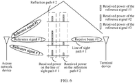
- FIG. 6 is a schematic diagram of received powers on different paths corresponding to different reference signals.
- the access network device sends three reference signals: a reference signal #1, a reference signal #2, and a reference signal #3, where the reference signal #2 is a reference reference signal.
- the reference signal #1, the reference signal #2, and the reference signal #3 may be a plurality of reference signals in a same reference signal set, for example, may be three reference signals in the first reference signal set.
- the first reference signal set corresponds to the access network device.
- a plurality of paths corresponding to the reference signals include a line of sight path #1 and a reflection path #2 shown in the figure. It should be understood that the reference signals may further include more paths.
- the terminal device receives the reference signal #1, the reference signal #2, and the reference signal #3 by using a receive beam #1.
- the receive beam #1 may be a receive beam that maximizes a received power of the reference signal #2 in a plurality of receive beams of the terminal device. It can be learned that, in received powers corresponding to the line of sight path #1 and the reflection path #2, the received power of the reference signal #2 on the line of sight path #1 is greater than received power on the reflection path #2. Therefore, the terminal device may report the received powers of the reference signal #1, the reference signal #2, and the reference signal #3 on the line of sight path #1.
- the received powers of the reference signal #1, the reference signal #2, and the reference signal #3 on the line of sight path #1 are used to determine a DAOD between the access network device and the terminal device.
- a DAOD DAOD between the access network device and the terminal device.
- FIG. 7 is a schematic diagram of received powers on different paths corresponding to different reference signals.
- a reference signal #1 and a reference signal #2 are used as reference reference signals.
- the upper figure in FIG. 7 is the same as FIG. 6 .
- the lower figure in FIG. 7 is a schematic diagram in which the terminal device receives reference signals by using a reference signal #1 as a reference reference signal. Referring to the lower figure in FIG. 7 , the terminal device receives the reference signal #1, a reference signal #2, and a reference signal #3 by using a receive beam #2.
- the receive beam #2 may be a receive beam that maximizes a received power of the reference signal #1 in a plurality of receive beams of the terminal device. It can be learned that, in received powers corresponding to the line of sight path #1 and the reflection path #2, the received power of the reference signal #1 on the reflection path #2 is greater than the received power on the line of sight path # 1. Therefore, in addition to reporting the received powers of the reference signal #1, the reference signal #2, and the reference signal #3 on the line of sight path #1, the terminal device may further report the received powers of the reference signal # 1, the reference signal #2, and the reference signal #3 on the reflection path #2. In addition, the terminal device may further report a delay difference between the line of sight path #1 and the reflection path #2.
- the received powers of the reference signal #1, the reference signal #2, and the reference signal #3 on the line of sight path #1 and the received power of the reference signal #1, the reference signal #2, and the reference signal #3 on the reflection path #2 may be used to determine a DAOD between the access network device and the terminal device.
- DAOD-based terminal device positioning may be further performed.
- the received powers of the reference signal #1, the reference signal #2, and the reference signal #3 on the line of sight path #1 are obtained by measuring the reference signals received by the receive beam #1.
- the received powers of the reference signal #1, the reference signal #2, and the reference signal #3 on the reflection path #2 are obtained by measuring the reference signals received by using the receive beam #2.
- each network element such as the positioning device or the terminal device, includes a corresponding hardware structure and/or software module for performing each function.
- a person skilled in the art may be aware that units and algorithm steps in the examples described with reference to the embodiments disclosed in this specification may be implemented by hardware or a combination of computer software and hardware. Whether a function is performed by hardware or hardware driven by computer software depends on particular applications and design constraints of the technical solutions. A person skilled in the art may use different methods to implement the described functions for each particular application, but it should not be considered that the implementation goes beyond the scope of this application.
- the positioning device or the terminal device may be divided into function modules based on the foregoing method examples.
- function modules may be obtained through division based on corresponding functions, or two or more functions may be integrated into one processing module.
- the foregoing integrated module may be implemented in a form of hardware, or may be implemented in a form of a software function module. It should be noted that, in the embodiments of this application, division into the modules is an example, and is merely logical function division. In actual implementation, another division manner may be used. An example in which functional modules are obtained through division based on functions is used below for description.
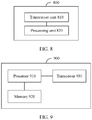
- FIG. 8 is a schematic block diagram of a communication apparatus 800 according to an embodiment of this application.
- the communication apparatus 800 includes a transceiver unit 810 and a processing unit 820.
- the transceiver unit 810 may communicate with the outside, and the processing unit 810 is configured to process data.
- the transceiver unit 810 may also be referred to as a communication interface or a communication unit.
- the communication apparatus 800 may be configured to perform an action performed by the terminal device in the foregoing method embodiments, or the communication apparatus 800 may be configured to perform an action performed by the positioning device in the foregoing method embodiments.
- the communication apparatus 800 may be configured to perform an action performed by the terminal device in the foregoing method embodiments.
- the communication apparatus 800 may be referred to as the terminal device.
- the transceiver unit 810 is configured to perform a sending/receiving-related operation on the terminal device side in the foregoing method embodiments
- the processing unit 820 is configured to perform a processing-related operation of the terminal device in the foregoing method embodiments.
- the transceiver unit 410 is configured to: receive resource configuration information, where the resource configuration information includes configuration information of a first reference signal set, the first reference signal set includes M reference signals, N reference signals in the M reference signals are reference reference signals, M is an integer greater than 1, and N is an integer greater than or equal to 1; and receive the M reference signals.
- the processing unit 820 is configured to: determine N first paths corresponding to the N reference reference signals, and determine M*N received powers of the M reference signals on the N first paths.
- the transceiver unit 810 is further configured to report a measurement result, where the measurement result includes K*N received powers in the M*N received powers, and K ⁇ M.
- the positioning device may match the received powers on the same path that are reported by the terminal device, with RSRPs that correspond to a plurality of beams at different exit angles and that are measured in advance by an access network device under a relatively ideal condition. Because under the relatively ideal condition, multipath generally does not exist, a matching result is more accurate, so that the positioning device can obtain a more accurate DAOD.
- the N reference reference signals correspond to N spatial receive filters.
- M received powers of the M reference signals on any first path j in the N first paths are M received powers, on the first path j, of the M reference signals received by using a spatial receive filter corresponding to a reference reference signal corresponding to the first path j.
- the K*N received powers include K largest received powers in M received powers on each first path in the N first paths, and K ⁇ M.
- the measurement result further includes identification information of K*N reference signals corresponding to the K*N received powers.
- the resource configuration information further includes configuration information of a second reference signal set, the second reference signal set includes P reference signals, Q reference signals in the P reference signals are reference reference signals, P is an integer greater than 1, and Q is an integer greater than or equal to 1;
- each of the spatial receive filters is a spatial receive filter that is in a plurality of spatial receive filters and that maximizes a received power of a reference reference signal corresponding to the spatial receive filter.
- each first path is a path with a largest received power in a plurality of paths that correspond to a reference reference signal corresponding to the first path.
- the measurement result further includes delays of N-1 first paths, in the N first paths except a reference first path, relative to the reference first path, where N is greater than 1.
- the measurement result further includes identification information of the N spatial receive filters.
- the communication apparatus 800 may be configured to perform an action performed by the positioning device in the foregoing method embodiments.
- the communication apparatus 800 may be referred to as the positioning device.
- the transceiver unit 810 is configured to perform a sending/receiving-related operation on the positioning device side in the foregoing method embodiments
- the processing unit 820 is configured to perform a processing-related operation of the positioning device in the foregoing method embodiments.
- the transceiver unit 810 is configured to: receive resource configuration information, where the resource configuration information includes configuration information of a first reference signal set, the first reference signal set includes M reference signals, N reference signals in the M reference signals are reference reference signals, M is an integer greater than 1, and N is an integer greater than or equal to 1; and receive the measurement result, where the measurement result includes K*N received powers in M*N received powers of the M reference signals on N first paths, the N first paths correspond to the N reference reference signals, and K ⁇ M.
- the processing unit 820 is configured to determine a downlink angle of departure DAOD based on the measurement result.
- the terminal device reports received powers on a same path
- the positioning device can obtain a more accurate DAOD based on the received powers on the same path.
- the positioning device may match the received powers on the same path that are reported by the terminal device, with RSRPs that correspond to a plurality of beams at different exit angles and that are measured in advance by an access network device under a relatively ideal condition. Because under the relatively ideal condition, multipath generally does not exist, a matching result is more accurate, so that the positioning device can obtain a more accurate DAOD.
- the N reference reference signals correspond to N spatial receive filters.
- M received powers of the M reference signals on any first path j in the N first paths are M received powers, on the first path j, of the M reference signals received by using a spatial receive filter corresponding to a reference reference signal corresponding to the first path j.
- the K*N received powers include K largest received powers in M received powers on each first path in the N first paths, and K ⁇ M.
- the measurement result further includes identification information of K reference signals corresponding to the K*N received powers.
- the resource configuration information further includes configuration information of a second reference signal set, the second reference signal set includes P reference signals, Q reference signals in the P reference signals are reference reference signals, P is an integer greater than 1, and Q is an integer greater than or equal to 1; and the measurement result further includes some or all of P*Q received powers of the P reference signals on Q first paths, and the Q first paths correspond to the Q reference reference signals.
- each of the spatial receive filters is a spatial receive filter that is in a plurality of spatial receive filters and that maximizes a received power of a reference reference signal corresponding to the spatial receive filter.
- each first path is a path with a largest received power in a plurality of paths that correspond to a reference reference signal corresponding to the first path.
- the measurement result further includes delays of N-1 first paths, in the N first paths except a reference first path, relative to the reference first path, where N is greater than 1.
- the measurement result further includes identification information of the N spatial receive filters.
- the communication apparatus 800 may be configured to perform an action performed by the access network device in the foregoing method embodiments.
- the communication apparatus 800 may be referred to as the access network device.
- the transceiver unit 810 is configured to perform a sending/receiving-related operation on the access network device side in the foregoing method embodiments
- the processing unit 820 is configured to perform a processing-related operation of the access network device in the foregoing method embodiments.
- the transceiver unit 810 is configured to send configuration information of a first reference signal set, where the first reference signal set includes M reference signals, N reference signals in the M reference signals are reference reference signals, M is an integer greater than 1, and N is an integer greater than or equal to 1; and the transceiver unit 810 is further configured to send the M reference signals.
- the transceiver unit 810 is further configured to receive a request message.
- the transceiver unit 810 is specifically configured to send the configuration information of the first reference signal set based on the request message.
- the transceiver unit 810 is further configured to receive K*N received powers in M*N received powers of the M reference signals on N first paths, where the N first paths correspond to the N reference reference signals, and K ⁇ M; and the processing unit 820 is configured to determine a downlink angle of departure DAOD based on the K*N received powers.
- the transceiver unit 810 is further configured to send information for indicating the DAOD.
- the processing unit 820 in the foregoing embodiment may be implemented by a processor or a processor-related circuit, and the transceiver unit 810 may be implemented by a transceiver or a transceiver-related circuit.
- an embodiment of this application further provides a communication apparatus 900.
- the communication apparatus 900 includes a processor 910, a memory 920, and a transceiver 930.
- the memory 920 stores a program.
- the processor 910 is configured to execute the program stored in the memory 920.
- the program stored in the memory 920 is executed, so that the processor 910 is configured to perform related processing steps in the foregoing method embodiment, and the program stored in the memory 920 is executed, so that the processor 910 controls the transceiver 930 to perform related sending and receiving steps in the foregoing method embodiment.
- the communication apparatus 900 is configured to perform an action performed by the terminal device in the foregoing method embodiments.
- the execution of the program stored in the memory 920 enables the processor 910 to perform processing steps on a terminal device side in the foregoing method embodiments, and enables the processor 910 to control the transceiver 930 to perform receiving and sending steps on the terminal device side in the foregoing method embodiments.
- the communication apparatus 900 is configured to perform an action performed by the positioning device in the foregoing method embodiments.
- the execution of the program stored in the memory 920 enables the processor 910 to perform processing steps on a positioning device side in the foregoing method embodiments, and enables the processor 910 to control the transceiver 930 to perform receiving and sending steps on the positioning device side in the foregoing method embodiments.
- An embodiment of this application further provides a communication apparatus 1000.
- the communication apparatus 1000 may be a terminal device or a chip.
- the communication apparatus 1000 may be configured to perform an action performed by the terminal device in the foregoing method embodiments.
- FIG. 10 is a simplified schematic structural diagram of the terminal device.
- the terminal device includes a processor, a memory, a radio frequency circuit, an antenna, and an input/output apparatus.
- the processor is mainly configured to: process a communication protocol and communication data, control the terminal device, execute a software program, process data of the software program, and so on.
- the memory is mainly configured to store the software program and data.
- the radio frequency circuit is mainly configured to: perform conversion between a baseband signal and a radio frequency signal, and process the radio frequency signal.
- the antenna is mainly configured to receive and transmit a radio frequency signal in an electromagnetic wave form.
- the input/output apparatus such as a touchscreen, a display screen, or a keyboard, is mainly configured to: receive data entered by a user, and output data to the user. It should be noted that some types of terminal devices may have no input/output apparatus.
- the processor When data needs to be sent, after performing baseband processing on the to-be-sent data, the processor outputs a baseband signal to the radio frequency circuit; and the radio frequency circuit performs radio frequency processing on the baseband signal and then sends a radio frequency signal to the outside in a form of an electromagnetic wave by using the antenna.
- the radio frequency circuit receives a radio frequency signal through the antenna, converts the radio frequency signal into a baseband signal, and outputs the baseband signal to the processor.
- the processor converts the baseband signal into data, and processes the data.
- FIG. 10 shows only one memory and one processor. In an actual terminal device product, there may be one or more processors and one or more memories.
- the memory may also be referred to as a storage medium, a storage device, or the like.
- the memory may be disposed independent of the processor, or may be integrated with the processor. This is not limited in the embodiments of this application.
- the antenna and the radio frequency circuit that have receiving and sending functions may be considered as a transceiver unit of the terminal device, and the processor that has a processing function may be considered as a processing unit of the terminal device.
- the terminal device includes a transceiver unit 1010 and a processing unit 1020.
- the transceiver unit 1010 may also be referred to as a transceiver, a transceiver machine, a transceiver apparatus, or the like.
- the processing unit 1020 may also be referred to as a processor, a processing board, a processing module, a processing apparatus, or the like.
- a component for implementing a receiving function in the transceiver unit 1010 may be considered as a receiving unit
- a component for implementing a sending function in the transceiver unit 1010 may be considered as a sending unit.
- the transceiver unit 1010 includes the receiving unit and the sending unit.
- the transceiver unit may also be sometimes referred to as a transceiver machine, a transceiver, a transceiver circuit, or the like.
- the receiving unit may also be sometimes referred to as a receiver machine, a receiver, a receiver circuit, or the like.
- the sending unit may also be sometimes referred to as a transmitter machine, a transmitter, a transmitter circuit, or the like.
- the processing unit 1020 is configured to perform S550 in FIG. 5 , and/or the processing unit 1020 is further configured to perform another processing step on the terminal device side in this embodiment of this application.
- the transceiver unit 1010 is further configured to perform S530, S540, and S550 shown in FIG. 5 , and/or the transceiver unit 1010 is further configured to perform another transceiver step on the terminal device side.
- FIG. 10 is merely an example instead of a limitation.
- the terminal device including the transceiver unit and the processing unit may not depend on the structure shown in FIG. 10 .
- the chip When the communication apparatus 1000 is a chip, the chip includes a transceiver unit and a processing unit.
- the transceiver unit may be an input/output circuit or a communication interface.
- the processing unit may be a processor, a microprocessor, or an integrated circuit integrated on the chip.
- An embodiment of this application further provides a communication apparatus 1100.
- the communication apparatus 1100 may be a positioning device or a chip.
- the communication apparatus 1100 may be configured to perform an action performed by the positioning device in the foregoing method embodiments.
- FIG. 11 is a simplified schematic structural diagram of the base station.
- the base station includes a part 1110 and a part 1120.
- the part 1110 is mainly configured to: send and receive a radio frequency signal, and perform conversion between the radio frequency signal and a baseband signal.
- the part 1120 is mainly configured to: perform baseband processing, control the base station, and so on.
- the part 1110 may be usually referred to as a transceiver unit, a transceiver machine, a transceiver circuit, a transceiver, or the like.
- the part 1120 is usually a control center of the base station, and may usually be referred to as a processing unit, and is configured to control the base station to perform a processing operation on a positioning device side in the foregoing method embodiments.
- the transceiver unit in the part 1110 may also be referred to as a transceiver machine, a transceiver, or the like.
- the transceiver unit includes an antenna and a radio frequency unit.
- the radio frequency unit is mainly configured to perform radio frequency processing.
- a component for implementing a receiving function in the part 1110 may be considered as a receiving unit, and a component for implementing a sending function may be considered as a sending unit. That is, the part 1110 includes the receiving unit and the sending unit.
- the receiving unit may also be referred to as a receiver machine, a receiver, a receiver circuit, or the like.
- the sending unit may be referred to as a transmitter machine, a transmitter, a transmitter circuit, or the like.
- the part 1120 may include one or more boards, and each board may include one or more processors and one or more memories.
- the processor is configured to read and execute a program in the memory to implement a baseband processing function and control the base station. If there are a plurality of boards, the boards may be interconnected to enhance a processing capability. In an optional implementation, alternatively, the plurality of boards may share one or more processors, or the plurality of boards share one or more memories, or the plurality of boards simultaneously share one or more processors.
- the transceiver unit in part 1110 is configured to perform the sending operation on the positioning device side in S530 in FIG. 5 , and the receiving operation on the network positioning device side in S560; and/or the transceiver unit in part 1110 is further configured to perform another transceiver step on the positioning device side in the embodiments of this application.
- the processing unit in part 1120 is configured to perform the processing operation in S570 in FIG. 5 ; and/or the processing unit in part 1120 is further configured to perform a processing step on a positioning device side in the embodiments of this application.
- FIG. 11 is merely an example instead of a limitation.
- the positioning device including the transceiver unit and the processing unit may not depend on the structure shown in FIG. 11 .
- the chip When the communication apparatus 1100 is a chip, the chip includes a transceiver unit and a processing unit.
- the transceiver unit may be an input/output circuit or a communication interface.
- the processing unit is a processor, a microprocessor, or an integrated circuit integrated on the chip.
- the communication apparatus 1100 may alternatively be an access network device, or a chip corresponding to the access network device.
- the communication apparatus 1100 may be configured to perform an action performed by the access network device in the foregoing method embodiments.
- the transceiver unit in part 1110 is configured to perform the sending operation on the access network device side in S520 in FIG. 5 .
- This embodiment of this application further provides a computer-readable storage medium.
- the computer-readable storage medium stores a computer program.
- the computer program When the computer program is executed by a computer, the computer is enabled to implement the method on a terminal device side or the method on the positioning device side in the foregoing method embodiments.
- This embodiment of this application further provides a computer program product including instructions.
- the instructions When the instructions are executed by a computer, the computer is enabled to implement the method on a terminal device side or the method on the positioning device side in the foregoing method embodiment.
- the terminal device or the positioning device includes a hardware layer, an operating system layer running above the hardware layer, and an application layer running above the operating system layer.
- the hardware layer includes hardware such as a central processing unit (central processing unit, CPU), a memory management unit (memory management unit, MMU), and a memory (also referred to as a main memory).
- the operating system may be any one or more of computer operating systems, for example, a Linux operating system, a Unix operating system, an Android operating system, an iOS operating system, or a Windows operating system, that implement service processing by using a process (process).
- the application layer includes applications such as a browser, an address book, word processing software, and instant communication software.
- a specific structure of an execution body of a method provided in the embodiments of this application is not specifically limited in the embodiments of this application, provided that a program that records code of the method provided in the embodiments of this application can be run to perform communication according to the method provided in the embodiments of this application.
- the execution body of the method provided in the embodiments of this application may be the terminal device or the positioning device, or a function module that can invoke and execute the program and that is in the terminal device or the positioning device.
- each aspect or feature of this application may be implemented as a method, an apparatus or a product that uses standard programming and/or engineering technologies.
- product used in this application covers a computer program that can be accessed from any computer-readable component, carrier, or medium.
- the computer-readable medium may include but is not limited to: a magnetic storage component (for example, a hard disk, a floppy disk, or a magnetic tape), an optical disc (for example, a compact disc (compact disc, CD) or a digital versatile disc (digital versatile disc, DVD)), a smart card, and a flash memory component (for example, an erasable programmable read-only memory (erasable programmable read-only memory, EPROM), a card, a stick, or a key drive).
- various storage media described in this specification may indicate one or more devices and/or other machine-readable media that are configured to store information.
- the term "machine-readable media” may include but is not limited to a wireless channel, and various other media that can store, include, and/or carry instructions and/or data.
- the processor mentioned in this embodiment of this application may be a central processing unit (Central Processing Unit, CPU), or another general-purpose processor, a digital signal processor (Digital Signal Processor, DSP), an application-specific integrated circuit (Application Specific Integrated Circuit, ASIC), a field programmable gate array (Field Programmable Gate Array, FPGA) or another programmable logic device, a discrete gate or a transistor logic device, a discrete hardware component, or the like.
- the general-purpose processor may be a microprocessor, or the processor may be any conventional processor or the like.
- the memory mentioned in this embodiment of this application may be a volatile memory or a nonvolatile memory, or may include a volatile memory and a nonvolatile memory.
- the nonvolatile memory may be a read-only memory (Read-Only Memory, ROM), a programmable read-only memory (Programmable ROM, PROM), an erasable programmable read-only memory (Erasable PROM, EPROM), an electrically erasable programmable read-only memory (Electrically EPROM, EEPROM), or a flash memory.
- the volatile memory may be a random access memory (Random Access Memory, RAM), used as an external cache.
- RAMs may be used, for example, a static random access memory (Static RAM, SRAM), a dynamic random access memory (Dynamic RAM, DRAM), a synchronous dynamic random access memory (Synchronous DRAM, SDRAM), a double data rate synchronous dynamic random access memory (Double Data Rate SDRAM, DDR SDRAM), an enhanced synchronous dynamic random access memory (Enhanced SDRAM, ESDRAM), a synchlink dynamic random access memory (Synchlink DRAM, SLDRAM), and a direct rambus random access memory (Direct Rambus RAM, DR RAM).
- Static RAM static random access memory
- DRAM dynamic random access memory
- DRAM synchronous dynamic random access memory
- SDRAM synchronous dynamic random access memory
- DDR SDRAM double data rate synchronous dynamic random access memory
- Enhanced SDRAM, ESDRAM enhanced synchronous dynamic random access memory
- Synchlink dynamic random access memory Synchlink dynamic random access memory
- SLDRAM direct rambus random access memory
- Direct Rambus RAM Direct Rambus RAM
- the processor is a general-purpose processor, a DSP, an ASIC, an FPGA or another programmable logic device, a discrete gate or a transistor logic device, or a discrete hardware component
- the memory is integrated into the processor.
- the memory described in this specification aims to include but is not limited to these memories and any memory of another proper type.
- an "embodiment” in the entire specification means that particular characteristics, structures, or features related to the embodiment are included in at least one embodiment of this application. Therefore, the embodiments in the entire specification do not necessarily refer to a same embodiment. In addition, these particular features, structures, or characteristics may be combined in one or more embodiments in any appropriate manner. It should be understood that sequence numbers of the foregoing processes do not mean execution sequences in various embodiments of this application. The execution sequences of the processes should be determined based on functions and internal logic of the processes, and should not be construed as any limitation on the implementation processes of the embodiments of this application.
- system and “network” may be used interchangeably in this specification.
- network may be used interchangeably in this specification.
- the term “and/or” in this specification describes only an association relationship for describing associated objects and represents that there may be three relationships. For example, A and/or B may represent the following three cases: Only A exists, both A and B exist, and only B exists.
- At least one of in this specification represents all or any combination of the listed items.
- “at least one of A, B, and C” may represent the following six cases: A exists alone, B exists alone, C exists alone, A and B coexist, B and C coexist, and A, B, and C coexist.
- B corresponding to A represents that B is associated with A, and B may be determined based on A.
- determining B based on A does not mean that B is determined based on only A.
- B may alternatively be determined based on A and/or other information.
- the disclosed system, apparatus, and method may be implemented in other manners.
- the described apparatus embodiments are merely examples.
- the unit division is merely logical function division and may be other division in actual implementation.
- a plurality of units or components may be combined or integrated into another system, or some features may be ignored or not performed.
- the displayed or discussed mutual couplings or direct couplings or communication connections may be implemented through some interfaces.
- the indirect couplings or communication connections between the apparatuses or units may be implemented in electrical, mechanical, or other forms.
- the units described as separate parts may or may not be physically separate, and parts displayed as units may or may not be physical units, may be located in one position, or may be distributed on a plurality of network units. Some or all of the units may be selected based on actual requirements to achieve the objectives of the solutions of the embodiments.
- function units in the embodiments of this application may be integrated into one processing unit, or each of the units may exist alone physically, or two or more units may be integrated into one unit.
- the functions When functions are implemented in a form of a software function unit and sold or used as an independent product, the functions may be stored in a computer-readable storage medium. Based on such an understanding, the technical solutions of this application essentially, or the part contributing to the conventional technology, or some of the technical solutions may be implemented in a form of a software product.
- the computer software product is stored in a storage medium, and includes several instructions for instructing a computer device (which may be a personal computer, a server, a network device, or the like) to perform all or some of the steps of the methods described in the embodiments of this application.
- the foregoing storage medium includes: any medium that can store program code, such as a USB flash drive, a removable hard disk, a read-only memory (read-only memory, ROM), a random access memory (random access memory, RAM), a magnetic disk, or an optical disc.
- program code such as a USB flash drive, a removable hard disk, a read-only memory (read-only memory, ROM), a random access memory (random access memory, RAM), a magnetic disk, or an optical disc.
Landscapes
- Engineering & Computer Science (AREA)
- Signal Processing (AREA)
- Computer Networks & Wireless Communication (AREA)
- Physics & Mathematics (AREA)
- General Physics & Mathematics (AREA)
- Radar, Positioning & Navigation (AREA)
- Remote Sensing (AREA)
- Electromagnetism (AREA)
- Quality & Reliability (AREA)
- Power Engineering (AREA)
- Mobile Radio Communication Systems (AREA)
- Position Fixing By Use Of Radio Waves (AREA)
Applications Claiming Priority (2)
| Application Number | Priority Date | Filing Date | Title |
|---|---|---|---|
| CN201910118107.9A CN111586736B (zh) | 2019-02-15 | 2019-02-15 | 用于测量信号的方法和通信装置 |
| PCT/CN2020/074889 WO2020164517A1 (zh) | 2019-02-15 | 2020-02-12 | 用于测量信号的方法和通信装置 |
Publications (3)
| Publication Number | Publication Date |
|---|---|
| EP3923620A1 true EP3923620A1 (de) | 2021-12-15 |
| EP3923620A4 EP3923620A4 (de) | 2022-04-27 |
| EP3923620B1 EP3923620B1 (de) | 2024-11-27 |
Family
ID=72044584
Family Applications (1)
| Application Number | Title | Priority Date | Filing Date |
|---|---|---|---|
| EP20756270.3A Active EP3923620B1 (de) | 2019-02-15 | 2020-02-12 | Verfahren zur messung eines signals und kommunikationsgerät |
Country Status (5)
| Country | Link |
|---|---|
| US (2) | US11658753B2 (de) |
| EP (1) | EP3923620B1 (de) |
| CN (2) | CN114501524A (de) |
| BR (1) | BR112021016021A2 (de) |
| WO (1) | WO2020164517A1 (de) |
Cited By (1)
| Publication number | Priority date | Publication date | Assignee | Title |
|---|---|---|---|---|
| EP4412290A4 (de) * | 2021-09-30 | 2025-02-05 | Datang Mobile Communications Equipment Co., Ltd. | Informationsübertragungsverfahren, messendgerät, ortsauflösendes endgerät, vorrichtung und speichermedium |
Families Citing this family (14)
| Publication number | Priority date | Publication date | Assignee | Title |
|---|---|---|---|---|
| CN114501524A (zh) * | 2019-02-15 | 2022-05-13 | 华为技术有限公司 | 用于测量信号的方法和通信装置 |
| US20200351814A1 (en) | 2019-05-02 | 2020-11-05 | Qualcomm Incorporated | Group delay timing accuracy for positioning in new radio |
| CN114765852A (zh) * | 2021-01-15 | 2022-07-19 | 大唐移动通信设备有限公司 | 定位角度校准方法及装置 |
| CN114828205A (zh) | 2021-01-18 | 2022-07-29 | 大唐移动通信设备有限公司 | 终端定位方法及设备 |
| EP4315705A4 (de) * | 2021-03-29 | 2025-05-21 | Nokia Technologies Oy | Sendebeaformer zur positionierung |
| CN115529661B (zh) * | 2021-06-25 | 2025-09-23 | 维沃移动通信有限公司 | 定位处理方法、定位参考信号发送方法、装置及设备 |
| CN115696365A (zh) * | 2021-07-23 | 2023-02-03 | 维沃移动通信有限公司 | 感知信号测量方法、装置、网络设备及终端 |
| CN115884249A (zh) * | 2021-09-29 | 2023-03-31 | 华为技术有限公司 | 一种通信方法及通信装置 |
| CN116614875B (zh) * | 2022-02-08 | 2026-04-03 | 维沃移动通信有限公司 | 组定位方法、装置、用户设备及存储介质 |
| CN116420372A (zh) * | 2023-02-06 | 2023-07-11 | 北京小米移动软件有限公司 | 一种反馈方法、装置、设备及存储介质 |
| CN119485138A (zh) * | 2023-08-11 | 2025-02-18 | 华为技术有限公司 | 一种定位方法、装置、芯片系统及存储介质 |
| CN120120999A (zh) * | 2023-12-08 | 2025-06-10 | 华为技术有限公司 | 发送测量信息的方法和通信装置 |
| CN121888365A (zh) * | 2024-10-17 | 2026-04-17 | 华为技术有限公司 | 测量上报方法及相关装置 |
| CN119788126B (zh) * | 2025-03-12 | 2025-08-12 | 蔚来汽车科技(安徽)有限公司 | 基于超宽带的通信环境识别方法和装置、智能设备和介质 |
Family Cites Families (17)
| Publication number | Priority date | Publication date | Assignee | Title |
|---|---|---|---|---|
| CN102045838B (zh) * | 2009-10-14 | 2013-06-12 | 电信科学技术研究院 | 一种观察到达时间差测量定位方法及设备 |
| JP6027988B2 (ja) * | 2012-01-25 | 2016-11-16 | パナソニック インテレクチュアル プロパティ コーポレーション オブ アメリカPanasonic Intellectual Property Corporation of America | 端末、基地局、送信方法及び受信方法 |
| WO2014201638A1 (zh) * | 2013-06-19 | 2014-12-24 | 华为技术有限公司 | 一种通信质量测量的方法和装置 |
| US10306597B2 (en) * | 2015-07-21 | 2019-05-28 | Samsung Electronics Co., Ltd. | Method and apparatus for beam-level radio resource management and mobility in cellular network |
| CN105589506B (zh) | 2016-02-29 | 2017-10-17 | 华为技术有限公司 | 功率跟踪方法、装置及光伏发电系统 |
| WO2017164220A1 (ja) * | 2016-03-25 | 2017-09-28 | 株式会社Nttドコモ | ユーザ端末、無線基地局及び無線通信方法 |
| EP4340251A3 (de) * | 2016-11-02 | 2024-05-22 | InterDigital Patent Holdings, Inc. | Gruppenbasierte strahlverwaltung |
| CN108023631B (zh) * | 2016-11-04 | 2023-08-22 | 华为技术有限公司 | 传输信息的方法和设备 |
| CN108064056B (zh) * | 2016-11-08 | 2020-12-29 | 上海朗帛通信技术有限公司 | 一种ue、基站和服务中心的用于定位的方法和设备 |
| US10924175B2 (en) * | 2017-03-31 | 2021-02-16 | Apple Inc. | Beam management procedure triggering and signaling delivery in fall-back mode |
| CN108111286B (zh) * | 2017-11-17 | 2022-04-19 | 中兴通讯股份有限公司 | 信息发送、接收方法及装置、存储介质、处理器 |
| WO2019202366A1 (en) * | 2018-04-18 | 2019-10-24 | Telefonaktiebolaget Lm Ericsson (Publ) | Beamforming in cellular systems using the same feedback information for different physical channels |
| US11681010B2 (en) * | 2018-08-01 | 2023-06-20 | Apple Inc. | Measurements and reporting for user equipment (UE) positioning in wireless networks |
| US11963150B2 (en) * | 2018-11-01 | 2024-04-16 | Qualcomm Incorporated | Positioning enhancements for locating a mobile device in a wireless network |
| US11881905B2 (en) * | 2019-01-03 | 2024-01-23 | Samsung Electronics Co., Ltd. | Method and apparatus for interference measurement |
| US20200267684A1 (en) * | 2019-02-15 | 2020-08-20 | Mediatek Inc. | RSRP Reporting Methods for NR High Resolution Angle-based Downlink Positioning |
| CN114501524A (zh) * | 2019-02-15 | 2022-05-13 | 华为技术有限公司 | 用于测量信号的方法和通信装置 |
-
2019
- 2019-02-15 CN CN202210046612.9A patent/CN114501524A/zh active Pending
- 2019-02-15 CN CN201910118107.9A patent/CN111586736B/zh active Active
-
2020
- 2020-02-12 WO PCT/CN2020/074889 patent/WO2020164517A1/zh not_active Ceased
- 2020-02-12 BR BR112021016021-3A patent/BR112021016021A2/pt unknown
- 2020-02-12 EP EP20756270.3A patent/EP3923620B1/de active Active
-
2021
- 2021-08-13 US US17/401,593 patent/US11658753B2/en active Active
-
2023
- 2023-04-17 US US18/301,442 patent/US12255693B2/en active Active
Cited By (1)
| Publication number | Priority date | Publication date | Assignee | Title |
|---|---|---|---|---|
| EP4412290A4 (de) * | 2021-09-30 | 2025-02-05 | Datang Mobile Communications Equipment Co., Ltd. | Informationsübertragungsverfahren, messendgerät, ortsauflösendes endgerät, vorrichtung und speichermedium |
Also Published As
| Publication number | Publication date |
|---|---|
| US20230327785A1 (en) | 2023-10-12 |
| EP3923620B1 (de) | 2024-11-27 |
| US12255693B2 (en) | 2025-03-18 |
| CN111586736B (zh) | 2022-01-14 |
| US11658753B2 (en) | 2023-05-23 |
| BR112021016021A2 (pt) | 2021-10-05 |
| US20210376940A1 (en) | 2021-12-02 |
| WO2020164517A1 (zh) | 2020-08-20 |
| EP3923620A4 (de) | 2022-04-27 |
| CN111586736A (zh) | 2020-08-25 |
| CN114501524A (zh) | 2022-05-13 |
Similar Documents
| Publication | Publication Date | Title |
|---|---|---|
| US12255693B2 (en) | Signal measurement method and communication apparatus | |
| US11647411B2 (en) | Beam measurement method, terminal and network device | |
| US11350425B2 (en) | Antenna panel training method and apparatus | |
| US11134406B2 (en) | Measurement reporting method and apparatus | |
| US12224812B2 (en) | Method for channel and interference measurement and device | |
| EP3606137A1 (de) | Verfahren und vorrichtung zur übermittlung von kanalqualitätsinformationen | |
| US12382328B2 (en) | Measurement reporting method and apparatus | |
| EP3813416B1 (de) | Kommunikationsverfahren und -vorrichtungen | |
| EP4185008A1 (de) | Verfahren und vorrichtung zur bestimmung von strahlinformationen und elektronische vorrichtung | |
| EP4120719A1 (de) | Kommunikationsverfahren und -vorrichtung | |
| EP4030644A1 (de) | Verfahren zur meldung von interferenzmessungen und kommunikationsvorrichtung | |
| EP4391411A1 (de) | Antennenerkennungsverfahren und -vorrichtung, vorrichtung und speichermedium | |
| CN113973369A (zh) | 获取、指示通信资源的方法、装置及电子设备 | |
| US20230042335A1 (en) | Quasi co-located relationship management method and apparatus | |
| US11218936B2 (en) | Method and device for handover | |
| EP3618298B1 (de) | Verfahren zur downlink-signalübertragung, endgerät und netzwerkvorrichtung | |
| CN115550954A (zh) | 资源测量方法和通信装置 | |
| EP3910848B1 (de) | Objektempfangsverfahren und -vorrichtung | |
| WO2025113062A1 (zh) | 一种波束管理方法及装置 | |
| CN118524534A (zh) | 一种信号传输的方法和通信装置 | |
| CN121175933A (zh) | 利用多接收链接收的基于l1的测量 |
Legal Events
| Date | Code | Title | Description |
|---|---|---|---|
| STAA | Information on the status of an ep patent application or granted ep patent |
Free format text: STATUS: THE INTERNATIONAL PUBLICATION HAS BEEN MADE |
|
| PUAI | Public reference made under article 153(3) epc to a published international application that has entered the european phase |
Free format text: ORIGINAL CODE: 0009012 |
|
| STAA | Information on the status of an ep patent application or granted ep patent |
Free format text: STATUS: REQUEST FOR EXAMINATION WAS MADE |
|
| 17P | Request for examination filed |
Effective date: 20210908 |
|
| AK | Designated contracting states |
Kind code of ref document: A1 Designated state(s): AL AT BE BG CH CY CZ DE DK EE ES FI FR GB GR HR HU IE IS IT LI LT LU LV MC MK MT NL NO PL PT RO RS SE SI SK SM TR |
|
| A4 | Supplementary search report drawn up and despatched |
Effective date: 20220325 |
|
| RIC1 | Information provided on ipc code assigned before grant |
Ipc: H04B 7/06 20060101ALN20220321BHEP Ipc: H04L 5/00 20060101ALN20220321BHEP Ipc: H04W 64/00 20090101ALI20220321BHEP Ipc: G01S 5/00 20060101ALI20220321BHEP Ipc: G01S 5/02 20100101AFI20220321BHEP |
|
| DAV | Request for validation of the european patent (deleted) | ||
| DAX | Request for extension of the european patent (deleted) | ||
| REG | Reference to a national code |
Ref country code: DE Free format text: PREVIOUS MAIN CLASS: H04W0024080000 Ref legal event code: R079 Ref document number: 602020042071 Country of ref document: DE Ipc: G01S0005020000 |
|
| GRAP | Despatch of communication of intention to grant a patent |
Free format text: ORIGINAL CODE: EPIDOSNIGR1 |
|
| STAA | Information on the status of an ep patent application or granted ep patent |
Free format text: STATUS: GRANT OF PATENT IS INTENDED |
|
| RIC1 | Information provided on ipc code assigned before grant |
Ipc: H04B 7/06 20060101ALN20240523BHEP Ipc: H04L 5/00 20060101ALN20240523BHEP Ipc: H04W 64/00 20090101ALI20240523BHEP Ipc: G01S 5/00 20060101ALI20240523BHEP Ipc: G01S 5/02 20100101AFI20240523BHEP |
|
| INTG | Intention to grant announced |
Effective date: 20240620 |
|
| GRAS | Grant fee paid |
Free format text: ORIGINAL CODE: EPIDOSNIGR3 |
|
| GRAA | (expected) grant |
Free format text: ORIGINAL CODE: 0009210 |
|
| STAA | Information on the status of an ep patent application or granted ep patent |
Free format text: STATUS: THE PATENT HAS BEEN GRANTED |
|
| AK | Designated contracting states |
Kind code of ref document: B1 Designated state(s): AL AT BE BG CH CY CZ DE DK EE ES FI FR GB GR HR HU IE IS IT LI LT LU LV MC MK MT NL NO PL PT RO RS SE SI SK SM TR |
|
| REG | Reference to a national code |
Ref country code: GB Ref legal event code: FG4D |
|
| REG | Reference to a national code |
Ref country code: CH Ref legal event code: EP |
|
| REG | Reference to a national code |
Ref country code: IE Ref legal event code: FG4D |
|
| REG | Reference to a national code |
Ref country code: DE Ref legal event code: R096 Ref document number: 602020042071 Country of ref document: DE |
|
| REG | Reference to a national code |
Ref country code: LT Ref legal event code: MG9D |
|
| REG | Reference to a national code |
Ref country code: NL Ref legal event code: MP Effective date: 20241127 |
|
| PG25 | Lapsed in a contracting state [announced via postgrant information from national office to epo] |
Ref country code: HR Free format text: LAPSE BECAUSE OF FAILURE TO SUBMIT A TRANSLATION OF THE DESCRIPTION OR TO PAY THE FEE WITHIN THE PRESCRIBED TIME-LIMIT Effective date: 20241127 Ref country code: IS Free format text: LAPSE BECAUSE OF FAILURE TO SUBMIT A TRANSLATION OF THE DESCRIPTION OR TO PAY THE FEE WITHIN THE PRESCRIBED TIME-LIMIT Effective date: 20250327 Ref country code: PT Free format text: LAPSE BECAUSE OF FAILURE TO SUBMIT A TRANSLATION OF THE DESCRIPTION OR TO PAY THE FEE WITHIN THE PRESCRIBED TIME-LIMIT Effective date: 20250327 |
|
| PG25 | Lapsed in a contracting state [announced via postgrant information from national office to epo] |
Ref country code: NL Free format text: LAPSE BECAUSE OF FAILURE TO SUBMIT A TRANSLATION OF THE DESCRIPTION OR TO PAY THE FEE WITHIN THE PRESCRIBED TIME-LIMIT Effective date: 20241127 Ref country code: FI Free format text: LAPSE BECAUSE OF FAILURE TO SUBMIT A TRANSLATION OF THE DESCRIPTION OR TO PAY THE FEE WITHIN THE PRESCRIBED TIME-LIMIT Effective date: 20241127 |
|
| REG | Reference to a national code |
Ref country code: AT Ref legal event code: MK05 Ref document number: 1746173 Country of ref document: AT Kind code of ref document: T Effective date: 20241127 |
|
| PG25 | Lapsed in a contracting state [announced via postgrant information from national office to epo] |
Ref country code: BG Free format text: LAPSE BECAUSE OF FAILURE TO SUBMIT A TRANSLATION OF THE DESCRIPTION OR TO PAY THE FEE WITHIN THE PRESCRIBED TIME-LIMIT Effective date: 20241127 |
|
| PG25 | Lapsed in a contracting state [announced via postgrant information from national office to epo] |
Ref country code: ES Free format text: LAPSE BECAUSE OF FAILURE TO SUBMIT A TRANSLATION OF THE DESCRIPTION OR TO PAY THE FEE WITHIN THE PRESCRIBED TIME-LIMIT Effective date: 20241127 |
|
| PG25 | Lapsed in a contracting state [announced via postgrant information from national office to epo] |
Ref country code: NO Free format text: LAPSE BECAUSE OF FAILURE TO SUBMIT A TRANSLATION OF THE DESCRIPTION OR TO PAY THE FEE WITHIN THE PRESCRIBED TIME-LIMIT Effective date: 20250227 |
|
| PG25 | Lapsed in a contracting state [announced via postgrant information from national office to epo] |
Ref country code: LV Free format text: LAPSE BECAUSE OF FAILURE TO SUBMIT A TRANSLATION OF THE DESCRIPTION OR TO PAY THE FEE WITHIN THE PRESCRIBED TIME-LIMIT Effective date: 20241127 Ref country code: GR Free format text: LAPSE BECAUSE OF FAILURE TO SUBMIT A TRANSLATION OF THE DESCRIPTION OR TO PAY THE FEE WITHIN THE PRESCRIBED TIME-LIMIT Effective date: 20250228 Ref country code: AT Free format text: LAPSE BECAUSE OF FAILURE TO SUBMIT A TRANSLATION OF THE DESCRIPTION OR TO PAY THE FEE WITHIN THE PRESCRIBED TIME-LIMIT Effective date: 20241127 |
|
| PG25 | Lapsed in a contracting state [announced via postgrant information from national office to epo] |
Ref country code: PL Free format text: LAPSE BECAUSE OF FAILURE TO SUBMIT A TRANSLATION OF THE DESCRIPTION OR TO PAY THE FEE WITHIN THE PRESCRIBED TIME-LIMIT Effective date: 20241127 |
|
| PG25 | Lapsed in a contracting state [announced via postgrant information from national office to epo] |
Ref country code: RS Free format text: LAPSE BECAUSE OF FAILURE TO SUBMIT A TRANSLATION OF THE DESCRIPTION OR TO PAY THE FEE WITHIN THE PRESCRIBED TIME-LIMIT Effective date: 20250227 |
|
| PG25 | Lapsed in a contracting state [announced via postgrant information from national office to epo] |
Ref country code: SM Free format text: LAPSE BECAUSE OF FAILURE TO SUBMIT A TRANSLATION OF THE DESCRIPTION OR TO PAY THE FEE WITHIN THE PRESCRIBED TIME-LIMIT Effective date: 20241127 |
|
| PG25 | Lapsed in a contracting state [announced via postgrant information from national office to epo] |
Ref country code: DK Free format text: LAPSE BECAUSE OF FAILURE TO SUBMIT A TRANSLATION OF THE DESCRIPTION OR TO PAY THE FEE WITHIN THE PRESCRIBED TIME-LIMIT Effective date: 20241127 |
|
| PG25 | Lapsed in a contracting state [announced via postgrant information from national office to epo] |
Ref country code: EE Free format text: LAPSE BECAUSE OF FAILURE TO SUBMIT A TRANSLATION OF THE DESCRIPTION OR TO PAY THE FEE WITHIN THE PRESCRIBED TIME-LIMIT Effective date: 20241127 |
|
| PG25 | Lapsed in a contracting state [announced via postgrant information from national office to epo] |
Ref country code: RO Free format text: LAPSE BECAUSE OF FAILURE TO SUBMIT A TRANSLATION OF THE DESCRIPTION OR TO PAY THE FEE WITHIN THE PRESCRIBED TIME-LIMIT Effective date: 20241127 |
|
| PG25 | Lapsed in a contracting state [announced via postgrant information from national office to epo] |
Ref country code: SK Free format text: LAPSE BECAUSE OF FAILURE TO SUBMIT A TRANSLATION OF THE DESCRIPTION OR TO PAY THE FEE WITHIN THE PRESCRIBED TIME-LIMIT Effective date: 20241127 |
|
| PG25 | Lapsed in a contracting state [announced via postgrant information from national office to epo] |
Ref country code: CZ Free format text: LAPSE BECAUSE OF FAILURE TO SUBMIT A TRANSLATION OF THE DESCRIPTION OR TO PAY THE FEE WITHIN THE PRESCRIBED TIME-LIMIT Effective date: 20241127 |
|
| PG25 | Lapsed in a contracting state [announced via postgrant information from national office to epo] |
Ref country code: IT Free format text: LAPSE BECAUSE OF FAILURE TO SUBMIT A TRANSLATION OF THE DESCRIPTION OR TO PAY THE FEE WITHIN THE PRESCRIBED TIME-LIMIT Effective date: 20241127 |
|
| REG | Reference to a national code |
Ref country code: DE Ref legal event code: R097 Ref document number: 602020042071 Country of ref document: DE |
|
| PG25 | Lapsed in a contracting state [announced via postgrant information from national office to epo] |
Ref country code: SE Free format text: LAPSE BECAUSE OF FAILURE TO SUBMIT A TRANSLATION OF THE DESCRIPTION OR TO PAY THE FEE WITHIN THE PRESCRIBED TIME-LIMIT Effective date: 20241127 |
|
| PG25 | Lapsed in a contracting state [announced via postgrant information from national office to epo] |
Ref country code: MC Free format text: LAPSE BECAUSE OF FAILURE TO SUBMIT A TRANSLATION OF THE DESCRIPTION OR TO PAY THE FEE WITHIN THE PRESCRIBED TIME-LIMIT Effective date: 20241127 |
|
| REG | Reference to a national code |
Ref country code: CH Ref legal event code: PL |
|
| PLBE | No opposition filed within time limit |
Free format text: ORIGINAL CODE: 0009261 |
|
| STAA | Information on the status of an ep patent application or granted ep patent |
Free format text: STATUS: NO OPPOSITION FILED WITHIN TIME LIMIT |
|
| PG25 | Lapsed in a contracting state [announced via postgrant information from national office to epo] |
Ref country code: LU Free format text: LAPSE BECAUSE OF NON-PAYMENT OF DUE FEES Effective date: 20250212 |
|
| PG25 | Lapsed in a contracting state [announced via postgrant information from national office to epo] |
Ref country code: CH Free format text: LAPSE BECAUSE OF NON-PAYMENT OF DUE FEES Effective date: 20250228 |
|
| 26N | No opposition filed |
Effective date: 20250828 |
|
| REG | Reference to a national code |
Ref country code: BE Ref legal event code: MM Effective date: 20250228 |
|
| PG25 | Lapsed in a contracting state [announced via postgrant information from national office to epo] |
Ref country code: FR Free format text: LAPSE BECAUSE OF NON-PAYMENT OF DUE FEES Effective date: 20250228 |
|
| PG25 | Lapsed in a contracting state [announced via postgrant information from national office to epo] |
Ref country code: BE Free format text: LAPSE BECAUSE OF NON-PAYMENT OF DUE FEES Effective date: 20250228 |
|
| PG25 | Lapsed in a contracting state [announced via postgrant information from national office to epo] |
Ref country code: IE Free format text: LAPSE BECAUSE OF NON-PAYMENT OF DUE FEES Effective date: 20250212 |
|
| PGFP | Annual fee paid to national office [announced via postgrant information from national office to epo] |
Ref country code: GB Payment date: 20260106 Year of fee payment: 7 |
|
| PGFP | Annual fee paid to national office [announced via postgrant information from national office to epo] |
Ref country code: DE Payment date: 20251230 Year of fee payment: 7 |