EP3924128B1 - Rotationsschneidkörper mit einsatztasche mit sitzfläche mit einer vielzahl von anschlagelementen, drehschneidwerkzeug und einsatz - Google Patents
Rotationsschneidkörper mit einsatztasche mit sitzfläche mit einer vielzahl von anschlagelementen, drehschneidwerkzeug und einsatz Download PDFInfo
- Publication number
- EP3924128B1 EP3924128B1 EP20706839.6A EP20706839A EP3924128B1 EP 3924128 B1 EP3924128 B1 EP 3924128B1 EP 20706839 A EP20706839 A EP 20706839A EP 3924128 B1 EP3924128 B1 EP 3924128B1
- Authority
- EP
- European Patent Office
- Prior art keywords
- insert
- abutment
- axial
- radial
- rotary cutting
- Prior art date
- Legal status (The legal status is an assumption and is not a legal conclusion. Google has not performed a legal analysis and makes no representation as to the accuracy of the status listed.)
- Active
Links
Images


Classifications
-
- B—PERFORMING OPERATIONS; TRANSPORTING
- B23—MACHINE TOOLS; METAL-WORKING NOT OTHERWISE PROVIDED FOR
- B23C—MILLING
- B23C5/00—Milling-cutters
- B23C5/02—Milling-cutters characterised by the shape of the cutter
- B23C5/06—Face-milling cutters, i.e. having only or primarily a substantially flat cutting surface
-
- B—PERFORMING OPERATIONS; TRANSPORTING
- B23—MACHINE TOOLS; METAL-WORKING NOT OTHERWISE PROVIDED FOR
- B23C—MILLING
- B23C5/00—Milling-cutters
- B23C5/02—Milling-cutters characterised by the shape of the cutter
- B23C5/10—Shank-type cutters, i.e. with an integral shaft
- B23C5/109—Shank-type cutters, i.e. with an integral shaft with removable cutting inserts
-
- B—PERFORMING OPERATIONS; TRANSPORTING
- B23—MACHINE TOOLS; METAL-WORKING NOT OTHERWISE PROVIDED FOR
- B23C—MILLING
- B23C5/00—Milling-cutters
- B23C5/16—Milling-cutters characterised by physical features other than shape
- B23C5/20—Milling-cutters characterised by physical features other than shape with removable cutter bits or teeth or cutting inserts
- B23C5/22—Securing arrangements for bits or teeth or cutting inserts
- B23C5/2204—Securing arrangements for bits or teeth or cutting inserts with cutting inserts clamped against the walls of the recess in the cutter body by a clamping member acting upon the wall of a hole in the insert
- B23C5/2208—Securing arrangements for bits or teeth or cutting inserts with cutting inserts clamped against the walls of the recess in the cutter body by a clamping member acting upon the wall of a hole in the insert for plate-like cutting inserts
- B23C5/2213—Securing arrangements for bits or teeth or cutting inserts with cutting inserts clamped against the walls of the recess in the cutter body by a clamping member acting upon the wall of a hole in the insert for plate-like cutting inserts having a special shape
-
- B—PERFORMING OPERATIONS; TRANSPORTING
- B23—MACHINE TOOLS; METAL-WORKING NOT OTHERWISE PROVIDED FOR
- B23C—MILLING
- B23C2200/00—Details of milling cutting inserts
- B23C2200/04—Overall shape
- B23C2200/0433—Parallelogram
- B23C2200/0438—Parallelogram rounded
-
- B—PERFORMING OPERATIONS; TRANSPORTING
- B23—MACHINE TOOLS; METAL-WORKING NOT OTHERWISE PROVIDED FOR
- B23C—MILLING
- B23C2200/00—Details of milling cutting inserts
- B23C2200/16—Supporting or bottom surfaces
- B23C2200/161—Supporting or bottom surfaces with projections
-
- B—PERFORMING OPERATIONS; TRANSPORTING
- B23—MACHINE TOOLS; METAL-WORKING NOT OTHERWISE PROVIDED FOR
- B23C—MILLING
- B23C2200/00—Details of milling cutting inserts
- B23C2200/16—Supporting or bottom surfaces
- B23C2200/164—Supporting or bottom surfaces discontinuous
-
- B—PERFORMING OPERATIONS; TRANSPORTING
- B23—MACHINE TOOLS; METAL-WORKING NOT OTHERWISE PROVIDED FOR
- B23C—MILLING
- B23C2200/00—Details of milling cutting inserts
- B23C2200/16—Supporting or bottom surfaces
- B23C2200/165—Supporting or bottom surfaces with one or more grooves
-
- B—PERFORMING OPERATIONS; TRANSPORTING
- B23—MACHINE TOOLS; METAL-WORKING NOT OTHERWISE PROVIDED FOR
- B23C—MILLING
- B23C2200/00—Details of milling cutting inserts
- B23C2200/16—Supporting or bottom surfaces
- B23C2200/168—Supporting or bottom surfaces with features related to indexing
-
- B—PERFORMING OPERATIONS; TRANSPORTING
- B23—MACHINE TOOLS; METAL-WORKING NOT OTHERWISE PROVIDED FOR
- B23C—MILLING
- B23C2200/00—Details of milling cutting inserts
- B23C2200/36—Other features of the milling insert not covered by B23C2200/04 - B23C2200/32
- B23C2200/361—Fixation holes
-
- B—PERFORMING OPERATIONS; TRANSPORTING
- B23—MACHINE TOOLS; METAL-WORKING NOT OTHERWISE PROVIDED FOR
- B23C—MILLING
- B23C2210/00—Details of milling cutters
- B23C2210/16—Fixation of inserts or cutting bits in the tool
- B23C2210/165—Fixation bolts
-
- B—PERFORMING OPERATIONS; TRANSPORTING
- B23—MACHINE TOOLS; METAL-WORKING NOT OTHERWISE PROVIDED FOR
- B23C—MILLING
- B23C2210/00—Details of milling cutters
- B23C2210/16—Fixation of inserts or cutting bits in the tool
- B23C2210/168—Seats for cutting inserts, supports for replacable cutting bits
-
- B—PERFORMING OPERATIONS; TRANSPORTING
- B23—MACHINE TOOLS; METAL-WORKING NOT OTHERWISE PROVIDED FOR
- B23C—MILLING
- B23C2210/00—Details of milling cutters
- B23C2210/20—Number of cutting edges
- B23C2210/202—Number of cutting edges three
-
- B—PERFORMING OPERATIONS; TRANSPORTING
- B23—MACHINE TOOLS; METAL-WORKING NOT OTHERWISE PROVIDED FOR
- B23C—MILLING
- B23C2210/00—Details of milling cutters
- B23C2210/40—Flutes, i.e. chip conveying grooves
- B23C2210/402—Flutes, i.e. chip conveying grooves of variable depth
- B23C2210/405—Flutes, i.e. chip conveying grooves of variable depth having decreasing depth in the direction of the shank from the tip of the tool
-
- B—PERFORMING OPERATIONS; TRANSPORTING
- B23—MACHINE TOOLS; METAL-WORKING NOT OTHERWISE PROVIDED FOR
- B23C—MILLING
- B23C2250/00—Compensating adverse effects during milling
- B23C2250/08—Compensating adverse effects during milling compensating centrifugal force
Definitions
- the present invention relates to a rotary cutting body having a plurality of abutment elements associated with a seat surface of an insert receiving pocket, and a rotary cutting tool having such cutting body, for use in metal cutting processes in general, and for ramp down milling operations and high speed milling operations in particular.
- a cutting body having at least one abutment element on a seat surface of an insert receiving pocket.
- US 5,542,795 discloses a milling cutter for performing plunge and face cutting operations on a workpiece with cutting inserts having different side and transverse cutting edges.
- a cutter body has a plurality of recessed insert seats for securably receiving the inserts, including a top shoulder spaced apart from the transverse cutting edges of the inserts for allowing the insert seat to receive inserts having transverse edges of different shapes, and a support structure for preventing relative movement between the cutting inserts and their respective seats along the side and transverse insert edges.
- the support structure includes a rail-like projection extending out of the back face of the cutting inserts that is substantially parallel to the side cutting edges of the insert, and a complementarily-shaped slot in the bottom wall of the seat, in combination with a shoulder formed in the insert seat near but spaced apart from the top shoulder of the seat, and a complementary recess in the insert substantially parallel to its transverse cutting edges.
- US 6,840,716 discloses a milling tool having an insert holder provided with an insert receiving pocket and at least one cutting insert mounted therein.
- the insert receiving pocket has a longitudinally extending inner wall, a rear wall adjacent the inner wall and a lower wall adjacent the inner wall and the rear wall.
- a front end of the lower wall protrudes forwardly with respect to a central portion of the insert holder.
- a front protrusion rises upwardly from the lower wall and extends inwardly and rearwardly from a periphery of the insert holder.
- the front protrusion has a front surface perpendicular to the lower wall.
- a groove formed in the bottom surface of the cutting insert has a distal side wall perpendicular to the bottom surface.
- a radial abutment surface of the cutting insert abuts a radial abutment surface of the insert receiving pocket
- the front surface of the front protrusion abuts the front distal side wall of the groove and a rear portion of the one cutting insert is spaced from the rear wall of the insert receiving pocket.
- a rotary cutting body as per the preamble of claim 1 and a rotary cutting tool as per the preamble of claim 9 are known from EP1952925A2 .
- a milling insert as per the preamble of claim 15 is known from EP1702703A1 .
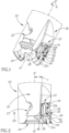
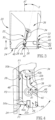
- one aspect of the present invention relates to a rotary cutting body 20 rotatable in a direction of rotation R about a tool axis AT, and having at least one insert receiving pocket 22 at an axial forward end 24 thereof.
- the insert receiving pocket 22 has a seat surface 26 facing in the direction of rotation R, a radially outward facing pocket wall 28 transverse to the seat surface 26, and a plurality of male and/or female abutment elements 30; 32a, 32b associated with the seat surface 26.
- the radially outward facing pocket wall 28 has an upper wall edge 48 spaced apart from the seat surface 26.
- the insert receiving pocket 22 may have an axially forward facing pocket wall 34 transverse to the seat surface 26 and spaced apart from the radially outward facing pocket wall 28.
- the axially forward facing pocket wall 34 may be entirely located axially rearward of the plurality of male and/or female abutment elements 30; 32a, 32b.
- the rotary cutting body 20 may be cylindrical shaped, having a circumferential wall 36 extending in an axial rearward direction DR from the axial forward end 24.
- the seat surface 26 includes a threaded bore 38 having a bore axis A1.
- the seat surface 26 may be planar.
- the bore axis A1 may be perpendicular to the seat surface 26.
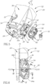
- the plurality of abutment elements 30; 32a, 32b include an axial abutment element 30 having an axially forward facing abutment surface 40 and at least one radial abutment element 32a, 32b having a radially inward facing abutment surface 42a, 42b.
- the plurality of abutment elements 30; 32a, 32b is elongated, wherein the axial abutment element 30 is transverse to the at least one radial abutment element 32a, 32b.
- the plurality of abutment elements 30; 32a, 32b may be male-type elements, for example, in the form of ribs or ridges.
- the plurality of abutment elements 30; 32a, 32b may include two spaced apart radial abutment elements 32a, 32b, a forward radial abutment element 32a and a rearward radial abutment element 32b.
- Each radial abutment element 32a, 32b may have a respective forward or rearward radially inward facing abutment surface 42a, 42b.
- the axially forward facing abutment surface 40 may intersect the circumferential wall 36.
- the plurality of abutment elements 30; 32a, 32b may only include a single axial abutment element 30.
- the seat surface 26 may include a knob 44 protruding therefrom.
- the knob 44 is spaced apart from all of the plurality of abutment elements 30; 32a, 32b.
- the knob 44 may be contiguous with the circumferential wall 36.
- an axial abutment edge 46 of the axially forward facing abutment surface 40 forms an external acute clamping angle ⁇ with a first plane P1 tangential to the wall edge 48 of the radially outward facing pocket wall 28 and intersecting the axial forward end 24.
- the axial abutment edge 46 may extend linearly along the axial abutment element 30.
- the wall edge 48 in the top view of the insert receiving pocket 22, may be linear, and the first plane P1 may contain the wall edge 48.
- the top view of the insert receiving pocket 22 may be taken perpendicular to the seat surface 26, and the first plane P1 may be perpendicular to the seat surface 26.
- the clamping angle ⁇ may be at least 45 degrees and at most 75 degrees.
- the bore axis A1 is located in the area of the seat surface 26 subtended by the clamping angle ⁇ .
- the bore axis A1 may not be perpendicular to the seat surface 26 (not shown), in the top view of the insert receiving pocket 22, the bore axis A1 may be considered to be located at the point of intersection of the bore axis A1 and an imaginary plane defined by the seat surface 26.
- the knob 44 may be located in the area of the seat surface 26 subtended by the clamping angle ⁇ .
- the axially forward facing abutment surface 40 may be entirely located further from the first plane P1 than the bore axis A1.
- the axially forward facing abutment surface 40 may intersect the threaded bore 38.
- the at least one radially inward facing abutment surface 42a, 42b may be entirely located closer to the first plane P1 than the bore axis A1.
- At least one radial abutment edge 50a, 50b of the at least one radially inward facing abutment surface 42a, 42b may be parallel to the first plane P1.
- the at least one radial abutment edge 50a, 50b may extend linearly along its respective radial abutment element 32a, 32b.
- the wall edge 48 of the radially outward facing pocket wall 28 may form a zero or acute first pocket angle ⁇ 1 with the tool axis AT, and the first pocket angle ⁇ 1 may be less than 15 degrees.
- the seat surface 26 may form a zero or acute second pocket angle ⁇ 2 with the tool axis AT, and the second pocket angle ⁇ 2 may be less than 30 degrees.
- the plurality of abutment elements 30; 32a, 32b include two spaced apart radial abutment elements 32a, 32b, in the top view of the insert receiving pocket 22, as shown in Fig. 4 , the two radial abutment elements 32a, 32b and their respective radially inward facing abutment surfaces 42a, 42b may be entirely located on opposite sides of a second plane P2 perpendicular to the first plane P1 and intersecting the threaded bore 38.
- the second plane P2 may contain the bore axis A1.
- the forward radial abutment element 32a may intersect the axial forward end 24, and the rearward radial abutment element 32b may intersect the axial abutment element 30.
- the elongated axial abutment element 30 and the elongated rearward radial abutment element 32b intersect at an obtuse angle to form a continuous boomerang-shaped rib 33 on which are formed both the axially forward facing abutment surface 40 and the rearward radially inward facing abutment surface 42b.
- the axially forward facing abutment surface 40 also forms an external acute clamping angle ⁇ with the rearward radially inward facing abutment surface 42b.
- the insert receiving pocket 22 seen in Figs. 4 and 5 has male-type abutment elements 30, 32a, 32b. It is understood, however, that in other embodiments a female axial abutment element and a female rearward radial abutment element may intersect to form a continuous boomerang-shaped groove.
- FIG. 5 and 6 another aspect of the present invention relates to a rotary cutting tool 52 having least one cutting insert 54 removably secured in the at least one insert receiving pocket 22 of the rotary cutter body 20.
- a plurality of cutting inserts 54 may be removably secured in an equal number of insert receiving pockets 22.
- the rotary cutting tool 52 may be a milling tool.
- the cutting insert 54 has opposing upper and lower surfaces 56, 58 with a peripheral side surface 60 extending therebetween, and a through bore 62 intersecting the upper and lower surfaces 56, 58 having an insert axis A2.
- the peripheral side surface 60 may comprise a pair of opposite end surfaces 75 connected to one another by a pair of opposite side surfaces 77.
- the cutting insert 54 may preferably be manufactured by form pressing and sintering a cemented carbide, such as tungsten carbide, and may be coated or uncoated.
- the upper and lower surfaces 56, 58 may differ from one another.
- the cutting insert 54 has two spaced apart cutting edges 64a, 64b formed at the intersection of the upper surface 56 and the peripheral side surface 60, and the cutting insert 54 is indexable about the insert axis A2.
- the cutting insert 54 may exhibit 2-fold rotational symmetry about the insert axis A2.
- the cutting insert 54 may be termed as 'single-sided' or 'non-reversible' .
- the lower surface 58 may have a base surface 66 and a plurality of male and/or female abutting elements 68a, 68b; 70a, 70b associated with the base surface 66.
- the base surface 66 may be planar.
- the plurality of abutting elements 68a, 68b; 70a, 70b may include at least one axial abutting element 68a, 68b and at least one radial abutting element 70a, 70b.
- the plurality of abutting elements 68a, 68b; 70a, 70b may be elongated, and the at least one axial abutting element 68a, 68b may be transverse to the at least one radial abutting element 70a, 70b.
- the plurality of abutting elements 68a, 68b; 70a, 70b may be female-type elements, for example, in the form of grooves or channels.
- the provision of the plurality of female-type abutting elements 68a, 68b; 70a, 70b contributes in reducing the overall weight of the cutting insert 54, which is very important in high speed milling operations, in which the cutting insert 54 is subjected to high centrifugal forces.
- the axial abutting surface 74a, 74b in contact with the axially forward facing abutment surface 40 may be described as an operative axial abutting surface 74a, 74b.
- clamping screw 72 may participate with the mounting of the cutting insert 54 in its respective insert receiving pocket 22.
- the plurality of abutting elements 68a, 68b; 70a, 70b may include two spaced apart axial abutting elements 68a, 68b.
- the axial abutting surface 74a, 74b of the axial abutting element 68a, 68b not in contact the axially forward facing abutment surface 40 may be described as a non-operative axial abutting surface 74a, 74b.
- the non-operative axial abutting surface 74a, 74b may not be in contact with any surface of the insert receiving pocket 22.
- a single male-type axial abutment element 30 may occupy a first of the two axial abutting elements 68a, 68b, and the knob 44 may occupy a second of the two axial abutting elements 68a, 68b.
- the cutting insert 54 has two spaced cutting edges 64a, 64b, and the cutting insert 54 is indexable about the insert axis A2, in the assembled position of the rotary cutting tool 52, wherein only one of the two spaced cutting edges 64a, 64b may be described as an operative cutting edge 64a, 64b.
- the plurality of abutting elements 68a, 68b; 70a, 70b may include two spaced apart radial abutting elements 70a, 70b.
- two spaced apart male-type radial abutment elements 32a, 32b may occupy the two radial abutting elements 70a, 70b.
- the plurality of abutting elements 68a, 68b; 70a, 70b are female-type.
- the insert's lower surface 58 has a single longitudinal groove 71 recessed into the base surface 66, opening to the opposite end surfaces 75, passing through the through bore 62, and comprising the two spaced apart radial abutting elements 70a, 70b.
- the insert's base surface 66 has a pair of parallel transverse grooves 69a, 69b recessed into the base surface 66, each transverse groove 69a, 69b opening out to the opposite side surfaces 77, avoiding the through bore 62, and comprising a respective one of the radial abutting elements 68a, 68b.
- the single longitudinal groove 71 intersects, and forms an acute groove angle ⁇ with, each of the transverse grooves 69a, 69b.
- the acute groove angle ⁇ is at least 45 degrees and at most 75 degrees.
- the bore axis A1 may be non-coaxial with the insert axis A2.
- the through bore 62 may be eccentric in relation to the threaded bore 38.
- the eccentric relationship of the through bore 62 in relation to the threaded bore 38 promotes contact between the axially forward facing abutment surface 40 of the axial abutment element 30 and the axial abutting surface 74a, 74b of the one of the at least one axial abutting element 68a, 68b on tightening of the clamping screw 72.
- the cutting insert 54 can be advantageously clamped in its respective insert receiving pocket 22 with a high level of stability.
- the clamping angle ⁇ is at least 45 degrees and at most 75 degrees
- the cutting insert 54 can be advantageously clamped in its respective insert receiving pocket 22 with a high level of stability.
- the cutting insert 54 can be advantageously clamped in its respective insert receiving pocket 22 with reduced level of rotational displacement about the bore axis A1 during milling operations, and particularly during ramp down milling operations.
- the radially outward facing pocket wall 28 may be in contact with the insert's peripheral side surface 60.
- the third plane P3 may be coincident with the second plane P2.
- the at least one radially inward facing abutment surface 42a, 42b may not be in contact with the cutting insert 54.
- the at least one radially inward facing abutment surface 42a, 42b may be perpendicular to the seat surface 26.
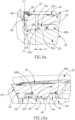
- the minimum first gap G1 may have a range of between 0.05 to 0.20 mm.
- Fig. 9a shows the minimum first gap G1 to an exaggerated scale to facilitate understanding of the invention.
- the at least one radial abutment element 32a, 32b may not be in contact with the cutting insert 54.
- no portion of the insert receiving pocket 22 may be in contact with the insert's peripheral side surface 60.
- the axially forward facing pocket wall 34 may be spaced apart from the insert's peripheral side surface 60.
- no portion of the knob 44 may be in contact with the axial abutting element 68a, 68b occupied thereby.
- the axially forward facing abutment surface 40 may be in contact with its corresponding axial abutting surface 74a, 74b.
- the axially forward facing abutment surface 40 may form an external obtuse abutment angle ⁇ with the bore surface 26.
- the abutment angle ⁇ may be greater than 100 degrees.
- the axial abutment element 30, and the axial abutting element 68a, 68b in contact therewith may be advantageously robust.
- the cutting insert 54 may undergo repositioning until each of the at least one radially inward facing abutment surface 42a, 42b may be in contact with a corresponding radial abutting surface 76a, 76b of the at least one radial abutting element 70a, 70b.
- the cutting insert 54 can be advantageously clamped in its respective insert receiving pocket 22 with a low level of radial displacement, and a magnitude comparable to the minimum first gap G1.
- the radially outward facing pocket wall 28 may not be in contact with the insert's peripheral side surface 60.
- the minimum second gap G2 may have a range of between 0.05 to 0.20 mm.
- Fig. 9b shows the minimum second gap G2 to an exaggerated scale to facilitate understanding of the invention.
- the axially forward facing abutment surface 40 may maintain contact with its corresponding axial abutting surface 74a, 74b.
- the radially outward facing pocket wall 28 in the presence of a sufficiently large radially outward force FR on the cutting insert 54, and in a cross-section taken in any plane perpendicular to the first plane P1 and intersecting the radially outward facing pocket wall 28, the radially outward facing pocket wall 28 may not be in contact with the insert's peripheral side surface 60.
- no portion of the insert receiving pocket 22 may be in contact with the insert's peripheral side surface 60.
- the axially forward facing pocket wall 34 may be spaced apart from the insert's peripheral side surface 60.
- the plurality of abutment elements 30; 32a, 32b include two spaced apart radial abutment elements 32a, 32b, and the plurality of abutting elements 68a, 68b; 70a, 70b include two spaced apart radial abutting elements 70a, 70b
- two radially inward facing abutment surfaces 42a, 42b of the two radial abutment elements 32a, 32b may be in contact with two corresponding radial abutting surfaces 76a, 76b of the two radial abutting elements 70a, 70b.
- no portion of the knob 44 may be in contact with its respective axial abutting element 68a, 68b.
- knob 44 may not participate with the mounting or positioning of the cutting insert 54 in its respective insert receiving pocket 22, but rather obstruct the entry of cutting chips into the respective axial abutting element 68a, 68b during machining operations, in order to protect the associated non-operative axial abutting surface 74a, 74b.
- the peripheral side surface 60 may be advantageously configured without constraints relating to axial abutment of the cutting insert 54 in its respective insert receiving pocket 22, thus allowing a wider range of insert shapes compatible with the insert receiving pocket 22, as well as minimal peripheral grinding of these inserts.
Landscapes
- Engineering & Computer Science (AREA)
- Mechanical Engineering (AREA)
- Milling Processes (AREA)
Claims (15)
- Rotierender Schneidkörper (20) mit einer Werkzeugachse (AT), um die der Schneidkörper in einer Drehrichtung (R) drehbar ist, mit:mindestens einer an einem axialen vorderen Ende (24) des Schneidkörpers (20) vorgesehenen Einsatzaufnahmetasche (22), wobei die Einsatzaufnahmetasche (22) aufweist:eine Sitzfläche (26), die in die Drehrichtung (R) weist und ein Gewindeloch (38) mit einer Lochachse (A1) aufweist;eine radial nach außen weisende Taschenwand (28) quer zur Sitzfläche (26), wobei die Taschenwand (28) einen von der Sitzfläche (26) beabstandeten Wandrand (48) aufweist;eine erste Ebene (P1), die sich tangential zum Wandrand (48) und senkrecht zur Sitzfläche (26) erstreckt und das axiale vordere Ende (24) des Schneidkörpers (20) schneidet; undeine Vielzahl von länglichen männlichen und/oder weiblichen Anliegeelementen (30; 32a, 32b), die der Sitzfläche (26) zugeordnet sind und aufweisen:ein axiales Anliegeelement (30) mit einer axial nach vorne gewandten Anliegefläche (40), wobei die axial nach vorne gewandte Anliegefläche (40) einen axialen Anliegerand (46) aufweist; undmindestens ein radiales Anliegeelement (32a, 32b) mit einer radial nach innen gewandten Anliegefläche (42a, 42b), wobei:
das axiale Anliegeelement (30) sich quer zu dem mindestens einen radialen Anliegeelement (32a, 32b) erstreckt, und wobei:
der axiale Anliegerand (46) in einer Draufsicht auf die Einsatzaufnahmetasche (22) einen äußeren spitzen Klemmwinkel (α) mit der ersten Ebene (P1) bildet,dadurch gekennzeichnet, dassdie Lochachse (A1) im Bereich der Sitzfläche (26) angeordnet ist, den der Klemmwinkel (α) überstreicht. - Rotierender Schneidkörper (20) nach Anspruch 1, wobei in der Draufsicht auf die Einsatzaufnahmetasche (22):
die axial nach vorne gewandte Anliegefläche (40) insgesamt weiter von der ersten Ebene (P1) entfernt ist als die Lochachse (A1). - Rotierender Schneidkörper (20) nach Anspruch 1 oder 2, wobei in der Draufsicht auf die Einsatzaufnahmetasche (22):
die axial nach vorne gewandte Anliegefläche (40) das Gewindeloch (38) schneidet. - Rotierender Schneidkörper (20) nach einem der vorangehenden Ansprüche, wobei in der Draufsicht auf die Einsatzaufnahmetasche (22):
die mindestens eine radial nach innen gewandte Anliegefläche (42a, 42b) vollständig näher an der ersten Ebene (P1) als an der Lochachse (A1) angeordnet ist. - Rotierender Schneidkörper (20) nach einem der vorangehenden Ansprüche, wobei in der Draufsicht auf die Einsatzaufnahmetasche (22):
mindestens ein radialer Anliegerand (50a, 50b) der mindestens einen radial nach innen gewandten Anliegefläche (42a, 42b) sich parallel zur ersten Ebene (P1) erstreckt. - Rotierender Schneidkörper (20) nach einem der vorhergehenden Ansprüche, wobeidie Vielzahl von Anliegeelementen (30; 32a, 32b) zwei voneinander beabstandete radiale Anliegeelemente (32a, 32b) aufweisen, wobei jedes radiale Anliegeelement (32a, 32b) eine radial nach innen gewandte Anliegefläche (42a, 42b) aufweist, undwobei in der Draufsicht auf die Einsatzaufnahmetasche (22):
die beiden radialen Anliegeelemente (32a, 32b) und ihre jeweiligen radial nach innen gewandten Anliegeflächen (42a, 42b) vollständig auf gegenüberliegenden Seiten einer zweiten Ebene (P2) angeordnet sind, die das Gewindeloch (38) schneidet und sich senkrecht zur ersten Ebene (P1) erstreckt. - Rotierender Schneidkörper (20) nach einem der vorangehenden Ansprüche, wobei:
der Klemmwinkel (α) mindestens 45 Grad und höchstens 75 Grad beträgt. - Rotierender Schneidkörper (20) nach einem der vorangehenden Ansprüche, wobei:die axial nach vorne gewandte Anliegefläche (40) einen äußeren stumpfen Anliegewinkel (β) mit der Sitzfläche (26) bildet, undder Anliegewinkel (β) größer als 100 Grad ist.
- Rotierendes Schneidwerkzeug (52), mit:
einem rotierenden Schneidkörper (20) mit einer Werkzeugachse (AT), um die der Schneidkörper in einer Drehrichtung (R) drehbar ist, mit:mindestens einer Einsatzaufnahmetasche (22), die an einem axialen vorderen Ende (24) des Schneidkörpers (20) vorgesehen ist, wobei die Einsatzaufnahmetasche (22) aufweist:eine Sitzfläche (26), die der Drehrichtung (R) zugewandt ist und ein Gewindeloch (38) mit einer Lochachse (A1) aufweist;eine radial nach außen gewandte Taschenwand (28) quer zur Sitzfläche (26), wobei die Taschenwand (28) einen von der Sitzfläche (26) beabstandeten Wandrand (48) aufweist;eine erste Ebene (P1), die sich tangential zum Wandrand (48) und senkrecht zur Sitzfläche (26) erstreckt und das axial vordere Ende (24) des Schneidkörpers (20) schneidet, undeine Vielzahl von männlichen und/oder weiblichen Anliegeelementen (30; 32a, 32b), die der Sitzfläche (26) zugeordnet sind und aufweisen:ein axiales Anliegeelement (30) mit einer axial nach vorne gewandten Anliegefläche (40), wobei die axial nach vorne gewandte Anliegefläche (40) einen axialen Anliegerand (46) aufweist; undmindestens ein radiales Anliegeelement (32a, 32b) mit einer radial nach innen gewandten Anliegefläche (42a, 42b),wobei in einer Draufsicht auf die Einsatzaufnahmetasche (22) der axiale Anliegerand (46) einen äußeren spitzen Klemmwinkel (α) mit der ersten Ebene (P1) bildet; undmindestens einem Schneideinsatz (54), der abnehmbar in der mindestens einen Einsatzaufnahmetasche (22) befestigt ist, wobei der Schneideinsatz (54) aufweist:eine obere und eine untere Fläche (56, 58), die einander gegenüberliegen und eine sich dazwischen erstreckende Umfangsseitenfläche (60) und ein die obere und die untere Fläche (56, 58) schneidendes Durchgangsloch (62) mit einer Einsatzachse (A2) aufweisen, um die der Schneideinsatz (54) wendbar ist;zwei voneinander beabstandete Schneidkanten (64a, 64b), die an der Schnittlinie der oberen Fläche (56) mit der Umfangsseitenfläche (60) ausgebildet sind, undwobei die untere Fläche (58) eine Basisfläche (66) und eine Vielzahl von männlichen und/oder weiblichen Anliegeelementen (68a, 68b; 70a, 70b) aufweist, die der Basisfläche (66) zugeordnet sind, wobeidie Vielzahl von Anliegeelementen (68a, 68b; 70a, 70b) mindestens ein axiales Anliegeelement (68a, 68b) und mindestens ein radiales Anliegeelement (70a, 70b) aufweisen,wobei eine Klemmschraube (72) sich durch das Durchgangsloch (62) erstreckt und mit dem Gewindeloch (38) in Gewindeeingriff steht, wobei:das mindestens eine radiale Anliegeelement (32a, 32b) das mindestens eine radiale Anliegeelement (70a, 70b) überdeckt oder von diesem überdeckt wird, unddie axial nach vorne gewandte Anliegefläche (40) mit einer entsprechenden axialen Anliegefläche (74a, 74b) eines unter dem mindestens einen axialen Anliegeelement (68a, 68b) in Kontakt steht,dadurch gekennzeichnet, dass die Basisfläche (66) des Einsatzes mit der Sitzfläche (26) in Kontakt steht. - Rotierendes Schneidwerkzeug (52) nach Anspruch 9, wobei:
die Lochachse (A1) sich nicht koaxial zur Einsatzachse (A2) erstreckt. - Rotierendes Schneidwerkzeug (52) nach Anspruch 9 oder 10, wobei:
eine Vielzahl von Schneideinsätzen (54) in einer gleichen Anzahl von Einsatzaufnahmetaschen (22) lösbar befestigt sind. - Rotierendes Schneidwerkzeug (52) nach einem der Ansprüche 9 bis 11, wobei:bei Abwesenheit einer radial nach außen gerichteten Kraft (FR) auf den Schneideinsatz (54) die mindestens eine radial nach innen gewandte Anliegefläche (42a, 42b) nicht mit dem Schneideinsatz (54) in Kontakt steht, und in einem Querschnitt, der in einer dritten Ebene (P3) senkrecht zur ersten Ebene (P1) genommen wird und den Wandrand (48) der radial nach außen gewandten Taschenwand (28) schneidet, die radial nach außen gewandte Taschenwand (28) mit der Umfangsseitenfläche (60) des Einsatzes in Kontakt steht, undbei Vorhandensein einer ausreichend großen radial nach außen gerichteten Kraft (FR) auf den Schneideinsatz (54) jede der mindestens einen radial nach innen gewandten Anliegefläche (42a, 42b) mit einer entsprechenden radialen Anliegefläche (76a, 76b) des mindestens einen radialen Anliegeelements (70a, 70b) in Kontakt steht, und im Querschnitt, der in der dritten Ebene (P3) genommen wird, die radial nach außen gewandte Taschenwand (28) nicht mit der Umfangsseitenfläche (60) des Einsatzes in Kontakt steht.
- Rotierendes Schneidwerkzeug (52) nach einem der Ansprüche 9 bis 12, wobei:
bei Vorhandensein einer ausreichend großen, radial nach außen gerichteten Kraft (FR) auf den Schneideinsatz (54) und in einem Querschnitt, der in einer beliebigen Ebene senkrecht zur ersten Ebene (P1) genommen wird und die radial nach außen gewandte Taschenwand (28) schneidet, die radial nach außen gewandte Taschenwand (28) nicht mit der Umfangsseitenfläche (60) des Einsatzes in Kontakt steht. - Rotierendes Schneidwerkzeug (52) nach einem der Ansprüche 9 bis 13, wobei.
bei Vorhandensein einer ausreichend großen, radial nach außen gerichteten Kraft (FR) auf den Schneideinsatz (54) kein Abschnitt der Einsatzaufnahmetasche (22) mit der Umfangsseitenfläche (60) des Einsatzes in Kontakt steht. - Einseitiger Fräseinsatz (54), mit:einer oberen und einer unteren Fläche (56, 58), die einander gegenüberliegen und eine sich dazwischen erstreckende Umfangsseitenfläche (60) aufweisen, wobei die untere Fläche (58) eine Basisfläche (66) aufweist,wobei die Umfangsseitenfläche (60) ein Paar gegenüberliegende Endflächen (75) aufweist, die durch ein Paar gegenüberliegende Seitenflächen (77) miteinander verbunden sind;zwei beabstandeten Schneidkanten (64a, 64b), die an der Schnittlinie der oberen Fläche (56) mit der Umfangsseitenfläche (60) ausgebildet sind; undeinem Durchgangsloch (62), das die obere und die untere Fläche (56, 58) schneidet und eine Einsatzachse (A2) aufweist, um die der Schneideinsatz wendbar ist;einer Vielzahl von weiblichen Anliegeelementen (68a, 68b; 70a, 70b), die der Basisfläche (66) zugeordnet sind und zwei voneinander beabstandete axiale Anliegeelemente (68a, 68b) und zwei voneinander beabstandete radiale Anliegeelemente (70a, 70b) aufweisen,wobei die untere Fläche (58) des Einsatzes aufweist:eine einzelne Längsnut (71), die in die Basisfläche (66) eingelassen ist, sich zu den gegenüberliegenden Endflächen (75) hin öffnet, sich durch das Durchgangsloch (62) erstreckt und die beiden beabstandeten radialen Anliegeelemente (70a, 70b) aufweist;ein Paar parallele Quernuten (69a, 69b), die in die Basisfläche (66) eingelassen sind, wobei jede Quernut (69a, 69b) sich zu den gegenüberliegenden Seitenflächen (77) hin öffnet, dem Durchgangsloch (62) ausweicht und ein jeweiliges der beiden radialen Anliegeelemente (70a, 70b) aufweist,wobei die einzelne Längsnut (71) jede der Quernuten (69a, 69b) schneidet und mit diesen einen spitzen Nutenwinkel (γ) bildet,dadurch gekennzeichnet, dass der spitze Nutenwinkel (γ) mindestens 45 Grad und höchstens 75 Grad beträgt.
Applications Claiming Priority (2)
| Application Number | Priority Date | Filing Date | Title |
|---|---|---|---|
| US16/273,775 US11090740B2 (en) | 2019-02-12 | 2019-02-12 | Rotary cutting body having insert pocket with seat surface provided with a plurality of abutment elements and rotary cutting tool |
| PCT/IL2020/050081 WO2020165890A1 (en) | 2019-02-12 | 2020-01-20 | Rotary cutting body having insert pocket with seat surface provided with a plurality of abutment elements, rotary cutting tool and insert |
Publications (3)
| Publication Number | Publication Date |
|---|---|
| EP3924128A1 EP3924128A1 (de) | 2021-12-22 |
| EP3924128B1 true EP3924128B1 (de) | 2024-10-23 |
| EP3924128C0 EP3924128C0 (de) | 2024-10-23 |
Family
ID=69650670
Family Applications (1)
| Application Number | Title | Priority Date | Filing Date |
|---|---|---|---|
| EP20706839.6A Active EP3924128B1 (de) | 2019-02-12 | 2020-01-20 | Rotationsschneidkörper mit einsatztasche mit sitzfläche mit einer vielzahl von anschlagelementen, drehschneidwerkzeug und einsatz |
Country Status (11)
| Country | Link |
|---|---|
| US (1) | US11090740B2 (de) |
| EP (1) | EP3924128B1 (de) |
| JP (1) | JP7518078B2 (de) |
| KR (1) | KR102720912B1 (de) |
| CN (1) | CN113396027B (de) |
| BR (1) | BR112021015635A2 (de) |
| CA (1) | CA3126221A1 (de) |
| IL (1) | IL284774B2 (de) |
| PL (1) | PL3924128T3 (de) |
| TW (1) | TWI814943B (de) |
| WO (1) | WO2020165890A1 (de) |
Families Citing this family (4)
| Publication number | Priority date | Publication date | Assignee | Title |
|---|---|---|---|---|
| JP7242997B2 (ja) * | 2019-02-18 | 2023-03-22 | 三菱マテリアル株式会社 | 刃先交換式エンドミルのエンドミル本体 |
| CN112108697B (zh) * | 2019-06-20 | 2024-08-06 | 肯纳金属印度有限公司 | 具有容纳间隙角不同的切割插入件的凹穴的工具固持器 |
| AT526451B1 (de) * | 2022-08-30 | 2024-04-15 | Mate Gmbh | Schneidwerkzeug mit einem Schneideinsatz |
| EP4670882A1 (de) * | 2024-06-28 | 2025-12-31 | AB Sandvik Coromant | Rotierendes schneidwerkzeug mit doppelseitigem wendeschneideinsatz |
Family Cites Families (43)
| Publication number | Priority date | Publication date | Assignee | Title |
|---|---|---|---|---|
| US3629919A (en) * | 1969-09-17 | 1971-12-28 | David J Trevarrow Jr | Tool and tool holder assembly |
| US4209047A (en) | 1978-06-28 | 1980-06-24 | Weill Theodore C | Debarker toe assembly |
| JP2539892Y2 (ja) * | 1991-11-07 | 1997-07-02 | 三菱マテリアル株式会社 | 切削工具 |
| US5924826A (en) | 1994-04-27 | 1999-07-20 | Sandvik Ab | Cutting insert mounted on holder by rib-and-groove coupling |
| US5542795A (en) | 1995-01-30 | 1996-08-06 | Kennametal Inc. | Plunge and face milling cutter with universal insert seats |
| IL112818A (en) | 1995-02-28 | 1999-10-28 | Iscar Ltd | Tool holder having a grooved seat |
| DK0830229T3 (da) * | 1995-06-06 | 2001-01-08 | Kennametal Inc | Højhastighedsfræser med kassetter |
| SE509363C2 (sv) * | 1995-09-25 | 1999-01-18 | Sandvik Ab | Fastspänningsanordning fjör skärplattor samt skärplatta avsedd för dylik anordning |
| SE511390C2 (sv) * | 1997-03-05 | 1999-09-20 | Sandvik Ab | Anordning vid fastspänning av skärplattor för skärande metallbearbetning |
| US5944456A (en) | 1997-12-04 | 1999-08-31 | Kennametal Inc. | Three dimensional mill and milling inserts |
| AT3955U1 (de) * | 1999-09-09 | 2000-11-27 | Plansee Tizit Aktiengesellscha | Rotierendes zerspanungswerkzeug |
| IL144154A0 (en) * | 2001-07-05 | 2002-05-23 | Iscar Ltd | Cutting tool and cutting insert therefor |
| CA2396919C (en) * | 2002-08-07 | 2006-01-31 | Lindsay Forest Products, Inc. | Log debarking tip |
| SE526109C2 (sv) | 2003-03-17 | 2005-07-05 | Seco Tools Ab | Fräsverktyg och indexerbart skär med samverkande utsprång och urtagningar |
| SE527851C2 (sv) * | 2004-02-11 | 2006-06-20 | Sandvik Intellectual Property | Skärverktyg, skär samt del till skärverktyg med serrationskopplingsytor |
| IL164023A (en) * | 2004-09-12 | 2009-07-20 | Gil Hecht | Cutting placement and cutting tools |
| SE527613C2 (sv) * | 2004-10-15 | 2006-04-25 | Seco Tools Ab | Verktyg för skärande bearbetning med en underläggsplatta med urtagningar |
| IL166007A (en) * | 2004-12-27 | 2009-02-11 | Iscar Ltd | Deburring tool and cutting insert therefor |
| SE528811C2 (sv) * | 2005-03-16 | 2007-02-20 | Sandvik Intellectual Property | Skär och verktyg för spånavskiljande bearbetning med vinklade ingreppsmedel, samt tillsats för dylika verktyg |
| SE0600876L (sv) * | 2006-04-20 | 2007-10-21 | Sandvik Intellectual Property | Verktyg och skär för spånavskiljande bearbetning med primära och sekundära ingreppsmedel med rotationssymmetrisk form |
| SE530629C2 (sv) * | 2006-12-12 | 2008-07-22 | Sandvik Intellectual Property | Verktyg och grundkropp för spånavskiljande bearbetning innefattande en elastiskt deformerbar fjäder i skärläget |
| SE530631C2 (sv) * | 2006-12-12 | 2008-07-22 | Sandvik Intellectual Property | Verktyg och skär för spånavskiljande bearbetning |
| SE530808C2 (sv) | 2007-01-31 | 2008-09-16 | Sandvik Intellectual Property | Verktyg för spånavskiljande bearbetning, samt skär och grundkropp härför |
| SE531502C2 (sv) * | 2007-06-05 | 2009-04-28 | Sandvik Intellectual Property | Verktyg för spånavskiljande bearbetning samt grundkropp och indexerbart skär härför |
| IL188502A (en) * | 2007-12-30 | 2012-05-31 | Iscar Ltd | Cutting insert and cutting tool therefor |
| SE532649C2 (sv) * | 2008-07-07 | 2010-03-09 | Sandvik Intellectual Property | Indexerbart frässkär |
| WO2010067910A1 (en) * | 2008-12-11 | 2010-06-17 | Taegutec Ltd. | Cutting tool |
| IL195984A0 (en) * | 2008-12-16 | 2009-09-01 | Iscar Ltd | Cutting tool and cutting insert therefor |
| US7922427B2 (en) * | 2008-12-18 | 2011-04-12 | Kennametal Inc. | Toolholder and toolholder assembly with elongated seating pads |
| KR101130466B1 (ko) * | 2009-01-23 | 2012-04-12 | 대구텍 유한회사 | 절삭 인서트, 공구 홀더 및 이들의 조립체 |
| US8573904B2 (en) * | 2011-06-14 | 2013-11-05 | Kennametal Inc. | Grooving insert |
| SE536345C2 (sv) * | 2012-01-20 | 2013-09-03 | Sandvik Intellectual Property | Håltagningsverktyg med bytbart skär innefattande han- och honartade säkringsmedel |
| AT512452A1 (de) * | 2012-02-01 | 2013-08-15 | Boehlerit Gmbh & Co Kg | Schneidplatte |
| US20130330136A1 (en) | 2012-06-06 | 2013-12-12 | Iscar, Ltd. | Cutting Insert and Tool Having an Anti-Slip Arrangement |
| US9339873B2 (en) | 2013-12-11 | 2016-05-17 | Iscar, Ltd. | Cutting insert having a dovetail anti-slip arrangement |
| US9481038B2 (en) | 2013-12-11 | 2016-11-01 | Iscar, Ltd. | Cutting insert having a dovetail anti-slip arrangement |
| CN203843259U (zh) * | 2014-04-29 | 2014-09-24 | 成都邦普合金材料有限公司 | 一种球头铣刀 |
| EP2992991A1 (de) * | 2014-09-05 | 2016-03-09 | Sandvik Intellectual Property AB | Schneideinsatz und Fräswerkzeug |
| EP3045246B1 (de) * | 2015-01-14 | 2021-07-14 | Sandvik Intellectual Property AB | Schneideinsatz und Fräswerkzeug |
| KR101677716B1 (ko) * | 2016-01-12 | 2016-11-18 | 한국야금 주식회사 | 절삭 인서트 및 이를 장착한 절삭 공구 |
| US10279400B2 (en) | 2017-01-30 | 2019-05-07 | Iscar, Ltd. | Indexable, single-sided cutting insert having two clamping bores and cutting tool therefor |
| DE102017000784A1 (de) | 2017-01-30 | 2018-08-02 | Iscar Ltd. | Einseitiger Wendeschneideinsatz mit zwei Klemmbohrungen und Schneidwerkzeug dafür |
| US10137510B1 (en) * | 2017-05-04 | 2018-11-27 | Ingersoll Cutting Tool Company | Rotary cutting tool having axially supported lead cutting insert and a continuous cutting edge |
-
2019
- 2019-02-12 US US16/273,775 patent/US11090740B2/en active Active
- 2019-11-15 TW TW108141517A patent/TWI814943B/zh not_active IP Right Cessation
-
2020
- 2020-01-20 EP EP20706839.6A patent/EP3924128B1/de active Active
- 2020-01-20 WO PCT/IL2020/050081 patent/WO2020165890A1/en not_active Ceased
- 2020-01-20 BR BR112021015635-6A patent/BR112021015635A2/pt not_active Application Discontinuation
- 2020-01-20 JP JP2021536718A patent/JP7518078B2/ja active Active
- 2020-01-20 KR KR1020217027141A patent/KR102720912B1/ko active Active
- 2020-01-20 IL IL284774A patent/IL284774B2/en unknown
- 2020-01-20 CA CA3126221A patent/CA3126221A1/en active Pending
- 2020-01-20 PL PL20706839.6T patent/PL3924128T3/pl unknown
- 2020-01-20 CN CN202080012414.XA patent/CN113396027B/zh active Active
Also Published As
| Publication number | Publication date |
|---|---|
| IL284774B2 (en) | 2024-11-01 |
| CN113396027A (zh) | 2021-09-14 |
| EP3924128C0 (de) | 2024-10-23 |
| TWI814943B (zh) | 2023-09-11 |
| BR112021015635A2 (pt) | 2021-10-05 |
| IL284774A (en) | 2021-08-31 |
| JP2022519440A (ja) | 2022-03-24 |
| JP7518078B2 (ja) | 2024-07-17 |
| KR20210125508A (ko) | 2021-10-18 |
| CA3126221A1 (en) | 2020-08-20 |
| WO2020165890A1 (en) | 2020-08-20 |
| US11090740B2 (en) | 2021-08-17 |
| KR102720912B1 (ko) | 2024-10-25 |
| CN113396027B (zh) | 2024-10-11 |
| US20200254540A1 (en) | 2020-08-13 |
| IL284774B1 (en) | 2024-07-01 |
| EP3924128A1 (de) | 2021-12-22 |
| PL3924128T3 (pl) | 2025-02-24 |
| TW202031440A (zh) | 2020-09-01 |
Similar Documents
| Publication | Publication Date | Title |
|---|---|---|
| EP2229253B1 (de) | Schneidwerkzeug | |
| EP3924128B1 (de) | Rotationsschneidkörper mit einsatztasche mit sitzfläche mit einer vielzahl von anschlagelementen, drehschneidwerkzeug und einsatz | |
| US9358622B2 (en) | Single sided indexable ramping milling insert and ramping milling tool | |
| EP2361166B1 (de) | Schneidwerkzeug und schneideinsatz dafür | |
| EP1401602B1 (de) | Schneidwerkzeug und dessen schneideinsatz | |
| EP2101947B1 (de) | Schneideinsatz und schneidwerkzeug | |
| US20100119313A1 (en) | Eight-Edged Cutting Insert, and Tool Holder for Same | |
| CN110497006B (zh) | 切削刀片以及切削工具 | |
| EP3266547B1 (de) | Schneideinsatz und schneidwerkzeug mit ersetzbarer schneidkante | |
| KR102622643B1 (ko) | 내측을 향하여 오프셋된 인서트 수용 슬롯을 갖는 슬로팅 공구 몸체, 이를 갖는 회전식 슬롯 절삭 공구 및 절삭 인서트 | |
| WO2016120099A1 (en) | A milling insert and a milling tool | |
| US8708613B2 (en) | Left-handed and right-handed cutting tool | |
| US10384278B2 (en) | Square-shaped cutting insert having curved secondary and corner cutting edges, and rotary cutting tool | |
| RU2770126C2 (ru) | Шлицевая фреза и инструментальный ключ в сочетании с ней | |
| KR102588549B1 (ko) | 편심 장착을 위한 상보적인 결합 특징부를 갖는 절삭 공구 및 절삭 인서트 | |
| RU2818240C2 (ru) | Вращаемое режущее тело, содержащее гнездо для вставки с посадочной поверхностью, снабженной множеством упорных элементов, вращаемый режущий инструмент и вставка | |
| HK40051491A (en) | Rotary cutting body having insert pocket with seat surface provided with a plurality of abutment elements, rotary cutting tool and insert |
Legal Events
| Date | Code | Title | Description |
|---|---|---|---|
| STAA | Information on the status of an ep patent application or granted ep patent |
Free format text: STATUS: UNKNOWN |
|
| STAA | Information on the status of an ep patent application or granted ep patent |
Free format text: STATUS: THE INTERNATIONAL PUBLICATION HAS BEEN MADE |
|
| PUAI | Public reference made under article 153(3) epc to a published international application that has entered the european phase |
Free format text: ORIGINAL CODE: 0009012 |
|
| STAA | Information on the status of an ep patent application or granted ep patent |
Free format text: STATUS: REQUEST FOR EXAMINATION WAS MADE |
|
| 17P | Request for examination filed |
Effective date: 20210910 |
|
| AK | Designated contracting states |
Kind code of ref document: A1 Designated state(s): AL AT BE BG CH CY CZ DE DK EE ES FI FR GB GR HR HU IE IS IT LI LT LU LV MC MK MT NL NO PL PT RO RS SE SI SK SM TR |
|
| DAV | Request for validation of the european patent (deleted) | ||
| DAX | Request for extension of the european patent (deleted) | ||
| GRAP | Despatch of communication of intention to grant a patent |
Free format text: ORIGINAL CODE: EPIDOSNIGR1 |
|
| STAA | Information on the status of an ep patent application or granted ep patent |
Free format text: STATUS: GRANT OF PATENT IS INTENDED |
|
| INTG | Intention to grant announced |
Effective date: 20240517 |
|
| RIN1 | Information on inventor provided before grant (corrected) |
Inventor name: ELKAYAM, SAGI |
|
| GRAS | Grant fee paid |
Free format text: ORIGINAL CODE: EPIDOSNIGR3 |
|
| GRAA | (expected) grant |
Free format text: ORIGINAL CODE: 0009210 |
|
| STAA | Information on the status of an ep patent application or granted ep patent |
Free format text: STATUS: THE PATENT HAS BEEN GRANTED |
|
| AK | Designated contracting states |
Kind code of ref document: B1 Designated state(s): AL AT BE BG CH CY CZ DE DK EE ES FI FR GB GR HR HU IE IS IT LI LT LU LV MC MK MT NL NO PL PT RO RS SE SI SK SM TR |
|
| REG | Reference to a national code |
Ref country code: GB Ref legal event code: FG4D |
|
| REG | Reference to a national code |
Ref country code: CH Ref legal event code: EP |
|
| REG | Reference to a national code |
Ref country code: DE Ref legal event code: R096 Ref document number: 602020039839 Country of ref document: DE |
|
| REG | Reference to a national code |
Ref country code: IE Ref legal event code: FG4D |
|
| U01 | Request for unitary effect filed |
Effective date: 20241121 |
|
| U07 | Unitary effect registered |
Designated state(s): AT BE BG DE DK EE FI FR IT LT LU LV MT NL PT RO SE SI Effective date: 20241127 |
|
| U20 | Renewal fee for the european patent with unitary effect paid |
Year of fee payment: 6 Effective date: 20241211 |
|
| PGFP | Annual fee paid to national office [announced via postgrant information from national office to epo] |
Ref country code: GB Payment date: 20241213 Year of fee payment: 6 |
|
| PG25 | Lapsed in a contracting state [announced via postgrant information from national office to epo] |
Ref country code: IS Free format text: LAPSE BECAUSE OF FAILURE TO SUBMIT A TRANSLATION OF THE DESCRIPTION OR TO PAY THE FEE WITHIN THE PRESCRIBED TIME-LIMIT Effective date: 20250223 Ref country code: HR Free format text: LAPSE BECAUSE OF FAILURE TO SUBMIT A TRANSLATION OF THE DESCRIPTION OR TO PAY THE FEE WITHIN THE PRESCRIBED TIME-LIMIT Effective date: 20241023 |
|
| PG25 | Lapsed in a contracting state [announced via postgrant information from national office to epo] |
Ref country code: ES Free format text: LAPSE BECAUSE OF FAILURE TO SUBMIT A TRANSLATION OF THE DESCRIPTION OR TO PAY THE FEE WITHIN THE PRESCRIBED TIME-LIMIT Effective date: 20241023 |
|
| PG25 | Lapsed in a contracting state [announced via postgrant information from national office to epo] |
Ref country code: NO Free format text: LAPSE BECAUSE OF FAILURE TO SUBMIT A TRANSLATION OF THE DESCRIPTION OR TO PAY THE FEE WITHIN THE PRESCRIBED TIME-LIMIT Effective date: 20250123 |
|
| PG25 | Lapsed in a contracting state [announced via postgrant information from national office to epo] |
Ref country code: GR Free format text: LAPSE BECAUSE OF FAILURE TO SUBMIT A TRANSLATION OF THE DESCRIPTION OR TO PAY THE FEE WITHIN THE PRESCRIBED TIME-LIMIT Effective date: 20250124 |
|
| PGFP | Annual fee paid to national office [announced via postgrant information from national office to epo] |
Ref country code: PL Payment date: 20241205 Year of fee payment: 6 |
|
| PG25 | Lapsed in a contracting state [announced via postgrant information from national office to epo] |
Ref country code: RS Free format text: LAPSE BECAUSE OF FAILURE TO SUBMIT A TRANSLATION OF THE DESCRIPTION OR TO PAY THE FEE WITHIN THE PRESCRIBED TIME-LIMIT Effective date: 20250123 |
|
| PG25 | Lapsed in a contracting state [announced via postgrant information from national office to epo] |
Ref country code: SM Free format text: LAPSE BECAUSE OF FAILURE TO SUBMIT A TRANSLATION OF THE DESCRIPTION OR TO PAY THE FEE WITHIN THE PRESCRIBED TIME-LIMIT Effective date: 20241023 |
|
| PG25 | Lapsed in a contracting state [announced via postgrant information from national office to epo] |
Ref country code: SK Free format text: LAPSE BECAUSE OF FAILURE TO SUBMIT A TRANSLATION OF THE DESCRIPTION OR TO PAY THE FEE WITHIN THE PRESCRIBED TIME-LIMIT Effective date: 20241023 |
|
| PG25 | Lapsed in a contracting state [announced via postgrant information from national office to epo] |
Ref country code: CZ Free format text: LAPSE BECAUSE OF FAILURE TO SUBMIT A TRANSLATION OF THE DESCRIPTION OR TO PAY THE FEE WITHIN THE PRESCRIBED TIME-LIMIT Effective date: 20241023 |
|
| PLBE | No opposition filed within time limit |
Free format text: ORIGINAL CODE: 0009261 |
|
| REG | Reference to a national code |
Ref country code: CH Ref legal event code: PL |
|
| STAA | Information on the status of an ep patent application or granted ep patent |
Free format text: STATUS: NO OPPOSITION FILED WITHIN TIME LIMIT |
|
| PG25 | Lapsed in a contracting state [announced via postgrant information from national office to epo] |
Ref country code: MC Free format text: LAPSE BECAUSE OF FAILURE TO SUBMIT A TRANSLATION OF THE DESCRIPTION OR TO PAY THE FEE WITHIN THE PRESCRIBED TIME-LIMIT Effective date: 20241023 |
|
| 26N | No opposition filed |
Effective date: 20250724 |
|
| PG25 | Lapsed in a contracting state [announced via postgrant information from national office to epo] |
Ref country code: CH Free format text: LAPSE BECAUSE OF NON-PAYMENT OF DUE FEES Effective date: 20250131 |
|
| PG25 | Lapsed in a contracting state [announced via postgrant information from national office to epo] |
Ref country code: IE Free format text: LAPSE BECAUSE OF NON-PAYMENT OF DUE FEES Effective date: 20250120 |