EP3924652B1 - Soupape pour corps encastré de robinetterie sanitaire munie d'un élément de régulation de débit et d'un élément de régulation de température - Google Patents
Soupape pour corps encastré de robinetterie sanitaire munie d'un élément de régulation de débit et d'un élément de régulation de température Download PDFInfo
- Publication number
- EP3924652B1 EP3924652B1 EP20704486.8A EP20704486A EP3924652B1 EP 3924652 B1 EP3924652 B1 EP 3924652B1 EP 20704486 A EP20704486 A EP 20704486A EP 3924652 B1 EP3924652 B1 EP 3924652B1
- Authority
- EP
- European Patent Office
- Prior art keywords
- valve
- regulating part
- liquid
- spindle
- temperature
- Prior art date
- Legal status (The legal status is an assumption and is not a legal conclusion. Google has not performed a legal analysis and makes no representation as to the accuracy of the status listed.)
- Active
Links
Images

Classifications
-
- F—MECHANICAL ENGINEERING; LIGHTING; HEATING; WEAPONS; BLASTING
- F16—ENGINEERING ELEMENTS AND UNITS; GENERAL MEASURES FOR PRODUCING AND MAINTAINING EFFECTIVE FUNCTIONING OF MACHINES OR INSTALLATIONS; THERMAL INSULATION IN GENERAL
- F16K—VALVES; TAPS; COCKS; ACTUATING-FLOATS; DEVICES FOR VENTING OR AERATING
- F16K19/00—Arrangements of valves and flow lines specially adapted for mixing fluids
- F16K19/006—Specially adapted for faucets
-
- F—MECHANICAL ENGINEERING; LIGHTING; HEATING; WEAPONS; BLASTING
- F16—ENGINEERING ELEMENTS AND UNITS; GENERAL MEASURES FOR PRODUCING AND MAINTAINING EFFECTIVE FUNCTIONING OF MACHINES OR INSTALLATIONS; THERMAL INSULATION IN GENERAL
- F16K—VALVES; TAPS; COCKS; ACTUATING-FLOATS; DEVICES FOR VENTING OR AERATING
- F16K11/00—Multiple-way valves, e.g. mixing valves; Pipe fittings incorporating such valves
- F16K11/02—Multiple-way valves, e.g. mixing valves; Pipe fittings incorporating such valves with all movable sealing faces moving as one unit
- F16K11/06—Multiple-way valves, e.g. mixing valves; Pipe fittings incorporating such valves with all movable sealing faces moving as one unit comprising only sliding valves, i.e. sliding closure elements
- F16K11/072—Multiple-way valves, e.g. mixing valves; Pipe fittings incorporating such valves with all movable sealing faces moving as one unit comprising only sliding valves, i.e. sliding closure elements with pivoted closure members
- F16K11/076—Multiple-way valves, e.g. mixing valves; Pipe fittings incorporating such valves with all movable sealing faces moving as one unit comprising only sliding valves, i.e. sliding closure elements with pivoted closure members with sealing faces shaped as surfaces of solids of revolution
-
- F—MECHANICAL ENGINEERING; LIGHTING; HEATING; WEAPONS; BLASTING
- F16—ENGINEERING ELEMENTS AND UNITS; GENERAL MEASURES FOR PRODUCING AND MAINTAINING EFFECTIVE FUNCTIONING OF MACHINES OR INSTALLATIONS; THERMAL INSULATION IN GENERAL
- F16K—VALVES; TAPS; COCKS; ACTUATING-FLOATS; DEVICES FOR VENTING OR AERATING
- F16K11/00—Multiple-way valves, e.g. mixing valves; Pipe fittings incorporating such valves
- F16K11/02—Multiple-way valves, e.g. mixing valves; Pipe fittings incorporating such valves with all movable sealing faces moving as one unit
- F16K11/08—Multiple-way valves, e.g. mixing valves; Pipe fittings incorporating such valves with all movable sealing faces moving as one unit comprising only taps or cocks
- F16K11/085—Multiple-way valves, e.g. mixing valves; Pipe fittings incorporating such valves with all movable sealing faces moving as one unit comprising only taps or cocks with cylindrical plug
-
- F—MECHANICAL ENGINEERING; LIGHTING; HEATING; WEAPONS; BLASTING
- F16—ENGINEERING ELEMENTS AND UNITS; GENERAL MEASURES FOR PRODUCING AND MAINTAINING EFFECTIVE FUNCTIONING OF MACHINES OR INSTALLATIONS; THERMAL INSULATION IN GENERAL
- F16K—VALVES; TAPS; COCKS; ACTUATING-FLOATS; DEVICES FOR VENTING OR AERATING
- F16K31/00—Actuating devices; Operating means; Releasing devices
- F16K31/12—Actuating devices; Operating means; Releasing devices actuated by fluid
- F16K31/36—Actuating devices; Operating means; Releasing devices actuated by fluid in which fluid from the circuit is constantly supplied to the fluid motor
- F16K31/38—Actuating devices; Operating means; Releasing devices actuated by fluid in which fluid from the circuit is constantly supplied to the fluid motor in which the fluid works directly on both sides of the fluid motor, one side being connected by means of a restricted passage and the motor being actuated by operating a discharge from that side
- F16K31/385—Actuating devices; Operating means; Releasing devices actuated by fluid in which fluid from the circuit is constantly supplied to the fluid motor in which the fluid works directly on both sides of the fluid motor, one side being connected by means of a restricted passage and the motor being actuated by operating a discharge from that side the fluid acting on a diaphragm
- F16K31/3855—Actuating devices; Operating means; Releasing devices actuated by fluid in which fluid from the circuit is constantly supplied to the fluid motor in which the fluid works directly on both sides of the fluid motor, one side being connected by means of a restricted passage and the motor being actuated by operating a discharge from that side the fluid acting on a diaphragm the discharge being effected through the diaphragm and being blockable by a mechanically-actuated member making contact with the diaphragm
-
- F—MECHANICAL ENGINEERING; LIGHTING; HEATING; WEAPONS; BLASTING
- F16—ENGINEERING ELEMENTS AND UNITS; GENERAL MEASURES FOR PRODUCING AND MAINTAINING EFFECTIVE FUNCTIONING OF MACHINES OR INSTALLATIONS; THERMAL INSULATION IN GENERAL
- F16K—VALVES; TAPS; COCKS; ACTUATING-FLOATS; DEVICES FOR VENTING OR AERATING
- F16K31/00—Actuating devices; Operating means; Releasing devices
- F16K31/44—Mechanical actuating means
- F16K31/52—Mechanical actuating means with crank, eccentric, or cam
- F16K31/524—Mechanical actuating means with crank, eccentric, or cam with a cam
- F16K31/52491—Mechanical actuating means with crank, eccentric, or cam with a cam comprising a diaphragm cut-off apparatus
Definitions
- the present invention relates to a valve for a concealed installation body of a sanitary fitting.
- Such concealed installation bodies can be attached within a wall opening, a recess in a wall or another support.
- Such concealed installation bodies have proven particularly useful in built-in walls and pre-wall systems.
- Concealed installation units are used to attach a functional unit to a wall, a wall or a support.
- the functional unit has previously comprised a thermostat cartridge and a valve.
- the thermostat cartridge can be used to mix cold water and hot water to form mixed water with a desired mixed water temperature, with the amount of mixed water drawn being controllable using the valve.
- a cold water connection of the concealed installation unit can be connected to a cold water house connection and a hot water connection of the concealed installation unit can be connected to a hot water house connection using appropriate pipes.
- At least one mixed water pipe can be connected to the concealed installation unit, via which the mixed water can be fed to the sanitary fitting, such as a hand shower, overhead shower, nozzle, spout and/or the like on a shower and/or bathtub.
- the mixed water can be fed from the thermostat cartridge to at least one valve via appropriate pipes in the functional unit, by means of which the flow rate of the liquid through the sanitary fitting can be controlled.
- Known valves for concealed installations have an actuating button for opening and closing the valve, which is located inside a rotating knob for adjusting a flow rate of the liquid through the valve.
- the division of the functional unit into a thermostat cartridge and a valve requires, on the one hand, more effort during assembly and, on the other hand, a larger installation space.
- valve knob, quantity control part and temperature control part now form the functional unit consisting of thermostat cartridge and valve in a common valve housing.
- the valve is intended for a concealed installation body that can be used in particular for sanitary fittings that are used in conjunction with showers and/or bathtubs.
- the sanitary fittings can in particular be water outlets, hand showers, overhead showers, nozzles and/or the like.
- the concealed installation body serves in particular to attach the valve.
- the valve now also comprises a temperature control part as a thermostat cartridge.
- a cold liquid hereinafter also referred to as cold water
- a warm liquid hereinafter also referred to as hot water
- the cold water can have a cold water temperature that is in particular a maximum of 25 °C (Celsius), preferably 1 °C to 25 °C, particularly preferably 5 °C to 20 °C.
- the hot water can have a hot water temperature that is in particular a maximum of 90 °C, preferably 25 °C to 90 °C, particularly preferably 55 °C to 65 °C.
- the valve is in particular at least partially arranged in a receiving space of a housing of the flush-mounted installation body and/or is essentially cylindrical. Such flush-mounted installation bodies are regularly attached within a wall opening, a recess in a wall or another support.
- the mixed water mixed by the temperature regulating part can be controlled in the valve by the quantity regulating part with regard to the withdrawal quantity of the mixed water via the sanitary fitting.
- the valve has a valve housing with a longitudinal axis.
- the valve housing can be used to attach the valve in particular to or in the flush-mounted installation body.
- the valve housing is at least partially tubular.
- the quantity control part can be operated in particular via a first rotary knob.
- the external thread spindle is rotationally fixed relative to the valve housing and can be adjusted (only) parallel to the longitudinal axis by means of the actuating button for opening and closing the valve.
- the external thread spindle is in particular cylindrical and has an external thread.
- the external thread is in particular not formed completely around the entire circumference of the external thread spindle, but preferably has at least two thread areas on its circumferential surface, which are spaced apart from one another in a circumferential direction by thread-free areas.
- the external thread can be used to adjust the (axial) relative position of the external thread spindle to neighboring components or to specify it during assembly.
- a toothing can be formed between the internal thread spindle and the valve button or (also) the quantity regulating part.
- the internal thread spindle can thus be rotated by rotating the first rotary knob or the quantity regulating part.
- the internal thread spindle can be adjusted parallel to the longitudinal axis by the valve button when the actuation button is pressed by a user.
- the internally threaded spindle can have at least one connecting nose that engages in the valve button.
- the second rotary knob can be arranged adjacent to the first rotary knob in the axial direction.
- the second rotary knob can be arranged at least partially (preferably completely) within the first rotary knob and covered by the first rotary knob along the axial direction, so that the second rotary knob cannot then be actuated by a user.
- an actuation can only take place when the actuation button has been actuated and the valve is activated to pass a flow rate to the extraction line.
- the mixing shaft can only be rotated in the circumferential direction but cannot be displaced in the axial direction by the spindle.
- the mixing shaft has an outer peripheral surface with at least one first passage for the warm liquid and at least one second passage for the cold liquid, wherein the mixing zone is arranged between the outer peripheral surface and the hub.
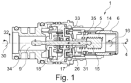
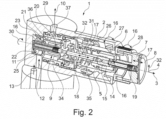
- the valve 1 has a flow rate adjustment zone 9, which is intended for adjusting the flow rate of a tempered liquid 10.
- the flow control part 5 interacts with an external thread spindle 15 via the valve button 6 and an internal thread spindle 14, so that a rotation 16 of the quantity regulating part 5 causes a rotation 16 of the valve knob 6 and the internal thread spindle 14 and a displacement of the external thread spindle 15 for adjusting the flow rate of the liquid along the axial direction 3.
- the external thread spindle 15 is rotationally fixed relative to the valve housing and can only be adjusted parallel to the longitudinal axis 4 by means of the actuating button 8 to open and close the valve 1.
- the external thread spindle 15 is cylindrical and has an external thread.
- the external thread is not formed completely around the entire circumference of the external thread spindle 15, but has at least two thread areas on its circumferential surface, which are spaced apart from one another in a circumferential direction 30 by thread-free areas.
- the external thread can be used to adjust the (axial) relative position of the external thread spindle 15 to adjacent components or to specify it firmly during assembly.
- the external thread spindle 15 is guided in at least one groove 35 of a guide 31.
- the guide 31 can neither be rotated relative to the valve housing 2 nor displaced parallel to the longitudinal axis 4.
- the external thread spindle 15 can be guided in the groove 35 parallel to the longitudinal axis 4 of the valve housing 1.
- the guide 31 has a plate-shaped base 33 which extends in a radial direction 32 of the valve housing 1.
- the at least one groove 35 extends from the plate-shaped base 33 parallel to the longitudinal axis 4.
- the external thread of the externally threaded spindle 15 extends through the at least one groove 35 in the radial direction 32 and thus interacts with the internal thread of the internally threaded spindle 14.
- a spindle 18 extends through the external thread spindle 15 along the longitudinal axis 4 and is connected to the external thread spindle 15 in such a way that the spindle 18 can be displaced along the axial direction 3 by the external thread spindle 15.
- a regulating body 34 can be actuated via the spindle 18 to adjust the flow rate of the liquid or the mixed water.
- the regulating body 34 can be displaced along the axial direction 3 with the spindle 18 by a displacement 17 to adjust the flow rate.
- the flow rate is adjusted exclusively as a function of the rotation 16 of the internal thread spindle 14.
- valve 1 additionally has a rotatable temperature regulating part 7 for setting a temperature of the liquid, wherein the valve button 6 is arranged coaxially to the quantity regulating part 5 and the temperature regulating part 7.
- the valve button 6, quantity regulating part 5 and temperature regulating part 7 form the functional unit consisting of the thermostat cartridge and the valve 1 in a common valve housing 2.
- the quantity regulating part 5 is connected in a rotationally fixed manner to the first rotary knob 27, via which a user can operate the quantity regulating part 5 to adjust the flow rate of the liquid.
- the flow rate of a tempered liquid 10 through the valve 1 to a withdrawal line 29 is controlled via the quantity regulating part 5.
- a spindle 18 extends through the external thread spindle 15 along the longitudinal axis 4 and is connected to the external thread spindle 15 such that the spindle 18 can be displaced along the axial direction 3 by the external thread spindle 15, with the spindle 18 being arranged so as to be rotatable relative to the external thread spindle 15.
- a regulating body 34 can be actuated via the spindle 18 to adjust the flow rate of the liquid or the mixed water. The regulating body 34 can be displaced along the axial direction 3 with the spindle 18 to adjust the flow rate.
- the flow rate is adjusted exclusively as a function of the rotation 16 of the first rotary knob 27 or the rotation of the internal thread spindle 14 (and not as a function of the displacement 17 of the internal thread spindle 14 along the axial direction 3 by the actuating knob 8).
- the spindle 18 is connected in a rotationally fixed manner to the rotatable temperature regulating part 7 at a first end 19.
- the temperature regulating part 7 is connected in a rotationally fixed manner to a second rotary knob 28 which can be operated by a user.
- the second rotary knob 28 is arranged adjacent to the first rotary knob 27 in the axial direction 3.
- the actuating knob 8 and the second rotary knob 28 are connected in a rotationally fixed manner to one another, wherein the actuating knob 8 is displaceable along the axial direction 3 relative to the second rotary knob 28 for opening and closing the valve 1 (by the actuating knob 8 actuating the valve knob 6).
- the first end 19 of the spindle 18 is connected in a rotationally fixed manner to the temperature regulating part 7 via an actuating button 8 that can be moved along the axial direction 3 relative to the valve housing 2 and the quantity regulating part 5 and actuates the valve button 6.
- the spindle 18 is also connected in a rotationally fixed manner to a rotatable mixing shaft 21 for adjusting the temperature of the liquid via a second end 20 (arranged along the axial direction 3 opposite the first end 19).
- the spindle 18 extends from the first end 19 through the regulating body 34 for adjusting the flow rate along the axial direction 3 to the second end 20.
- the mixing shaft 21 forms a mixing zone 11 for mixing a cold liquid 12 and a warm liquid 13 to form the tempered liquid 10 with a set temperature, the mixing shaft 21 having a hub 22 to which the second end 20 is connected in a rotationally fixed manner, the second end 20 being displaceable relative to the hub 22 along the axial direction 3.
- the mixing shaft 21 is thus only rotatable in the circumferential direction 30 but not displaceable in the axial direction 3 by the spindle 18.
- the mixing shaft 21 has an outer circumferential surface 23 with a first passage 24 for the warm liquid 13 and a second passage 25 for the cold liquid 12, the mixing zone 11 being arranged between the outer circumferential surface 23 and the hub 22.
- the tempered liquid 10 can then be the regulating body 34 and through the flow rate adjustment zone 9 to the extraction line 29.
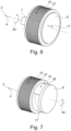
- Fig.6 shows a first rotary knob 27, second rotary knob 28 and actuating button 8 in a first arrangement to one another in a perspective view.
- Fig.7 shows the first rotary knob 27, second rotary knob 28 and operating button 8 after Fig.6 in a second arrangement to each other in perspective view.
- the Fig. 6 and 7 are described together below.
- the second rotary knob 28 is arranged completely within the first rotary knob 27 and is covered by the first rotary knob 27 along the axial direction 3, so that the second rotary knob 28 cannot then be actuated by a user.
- the second rotary knob 28 can only be actuated if the actuation button 8 has been actuated (see Fig.7 ) and the valve 1 is activated to pass a flow rate to the extraction line 29.
- the actuating button 8 can be displaced along the axial direction 3 by a displacement 17.
- the rotary knobs 27, 28 can be rotated in the circumferential direction 30 by a rotation 16.
Landscapes
- Engineering & Computer Science (AREA)
- General Engineering & Computer Science (AREA)
- Mechanical Engineering (AREA)
- Mechanically-Actuated Valves (AREA)
- Multiple-Way Valves (AREA)
- Domestic Plumbing Installations (AREA)
Claims (8)
- Soupape (1), destinée à un élément à encastrer d'une robinetterie sanitaire, comportant au moins :- un corps de soupape (2), comprenant un axe longitudinal (4) s'étendant le long d'une direction axiale (3),- une pièce de régulation du débit (5), destinée à régler un débit d'un liquide à travers la soupape (1),- un bouton de soupape (6), destiné à ouvrir et à fermer la soupape (1), et- une pièce de régulation thermique (7) rotative, destinée à régler une température du liquide ;au moins la pièce de régulation du débit (5) rotative et la pièce de régulation thermique (7) étant placées de manière coaxiale l'une par rapport à l'autre, le bouton de soupape (6) étant déplaçable par l'intermédiaire d'une tête d'actionnement (8) le long de la direction axiale (3) par rapport au corps de soupape (2) et à la pièce de régulation du débit (5), caractérisée en ce que la pièce de régulation du débit (5) coopère par l'intermédiaire du bouton de soupape (6) et d'une broche taraudée (14) avec une broche filetée (15), de telle sorte qu'une rotation (16) de la pièce de régulation du débit (5) provoque une rotation (16) de la broche taraudée (14) et un déplacement (17) le long de la direction axiale (3) de la broche filetée (15), pour le réglage du débit du liquide.
- Soupape (1) selon la revendication 1 du brevet, une zone de réglage (9) du débit, destinée à régler le débit d'un liquide (10) tempéré le long de la direction axiale (3) étant placée entre une zone de mélange (11), destinée au mélange d'un liquide froid (12) et d'un liquide chaud (13) pour obtenir le liquide tempéré (10) à une température de réglage et au moins le bouton de soupape (6).
- Soupape (1) selon l'une quelconque des revendications précédentes du brevet, une broche (18) s'étendant à travers la broche filetée (15) le long de l'axe longitudinal (4) et étant reliée avec la broche filetée (15) de telle sorte que la broche (18) soit déplaçable à travers la broche filetée (15) le long de la direction axiale (3), à cet effet, la broche (18) étant placée de manière rotative par rapport à la broche filetée (15).
- Soupape (1) selon la revendication 3 du brevet, la broche (18) étant reliée de manière solidaire en rotation par une première extrémité (19) avec la pièce de régulation thermique (7) rotative.
- Soupape (1) selon la revendication 4 du brevet, la première extrémité (19) étant reliée de manière solidaire en rotation, par l'intermédiaire d'un bouton d'actionnement (8) déplaçable le long de la direction axiale (3) par rapport au corps de soupape (2) et la pièce de régulation du débit (5) et actionnant le bouton de soupape (6) avec la pièce de régulation thermique (7).
- Soupape (1) selon l'une quelconque des revendications précédentes 3 à 5 du brevet, la broche (18) étant reliée de manière solidaire en rotation par l'intermédiaire d'une deuxième extrémité (20) avec un arbre mélangeur (21) rotatif, pour le réglage de la température du liquide.
- Soupape (1) selon la revendication 6, l'arbre mélangeur (21) formant une zone de mélange (11) pour le mélange d'un liquide froid (12) et d'un liquide chaud (13), pour obtenir le liquide tempéré (14) à une température réglée, l'arbre mélangeur (21) comportant un moyeu (22) avec lequel la deuxième extrémité (20) est reliée de manière solidaire en rotation, la deuxième extrémité (20) étant déplaçable le long de la direction axiale (3) par rapport au moyeu (22).
- Soupape (1) selon la revendication 7, l'arbre mélangeur (21) comportant une surface périphérique (23) extérieure, pourvue d'au moins un premier passage (24) pour le liquide chaud (13) et d'au moins un deuxième passage (25) pour le liquide froid (12), la zone de mélange (11) étant placée entre la surface périphérique (23) extérieure et le moyeu (22).
Applications Claiming Priority (2)
| Application Number | Priority Date | Filing Date | Title |
|---|---|---|---|
| DE102019103610.0A DE102019103610A1 (de) | 2019-02-13 | 2019-02-13 | Ventil für einen Unterputzeinbaukörper einer Sanitärarmatur mit einem Mengenregulierteil und einem Temperaturregulierteil |
| PCT/EP2020/052895 WO2020165002A1 (fr) | 2019-02-13 | 2020-02-05 | Soupape pour corps encastré de robinetterie sanitaire munie d'un élément de régulation de débit et d'un élément de régulation de température |
Publications (2)
| Publication Number | Publication Date |
|---|---|
| EP3924652A1 EP3924652A1 (fr) | 2021-12-22 |
| EP3924652B1 true EP3924652B1 (fr) | 2024-07-03 |
Family
ID=69528818
Family Applications (1)
| Application Number | Title | Priority Date | Filing Date |
|---|---|---|---|
| EP20704486.8A Active EP3924652B1 (fr) | 2019-02-13 | 2020-02-05 | Soupape pour corps encastré de robinetterie sanitaire munie d'un élément de régulation de débit et d'un élément de régulation de température |
Country Status (5)
| Country | Link |
|---|---|
| EP (1) | EP3924652B1 (fr) |
| DE (1) | DE102019103610A1 (fr) |
| ES (1) | ES2983666T3 (fr) |
| PL (1) | PL3924652T3 (fr) |
| WO (1) | WO2020165002A1 (fr) |
Families Citing this family (3)
| Publication number | Priority date | Publication date | Assignee | Title |
|---|---|---|---|---|
| CN110280412B (zh) * | 2019-06-05 | 2024-03-19 | 路达(厦门)工业有限公司 | 浴缸龙头 |
| EP4141303B1 (fr) * | 2021-08-26 | 2025-11-26 | Fabrizio Nobili | Dispositif d'actionnement de soupape |
| IT202200017823A1 (it) * | 2022-08-30 | 2024-03-01 | Fabrizio Nobili | Dispositivo di erogazione per unità di erogazione-acqua |
Citations (3)
| Publication number | Priority date | Publication date | Assignee | Title |
|---|---|---|---|---|
| US3645297A (en) * | 1970-03-30 | 1972-02-29 | A C Boultinghouse | Multiple adjustment valve |
| WO1992001883A1 (fr) * | 1990-07-23 | 1992-02-06 | Lin Zhixie | Robinet melangeur a bouton-poussoir |
| CN107990020A (zh) * | 2017-12-29 | 2018-05-04 | 厦门松霖科技股份有限公司 | 多功能阀 |
Family Cites Families (9)
| Publication number | Priority date | Publication date | Assignee | Title |
|---|---|---|---|---|
| US7134451B1 (en) * | 2004-01-09 | 2006-11-14 | Geberit Technik Ag | Metering faucet assembly including temperature control |
| US20090146090A1 (en) * | 2005-07-12 | 2009-06-11 | Inax Corporation | Pilot Type Water Discharging/Stopping and Flow Regulating Valve Device |
| JP6103198B2 (ja) * | 2013-02-12 | 2017-03-29 | パナソニックIpマネジメント株式会社 | 弁装置 |
| EP2865929B1 (fr) * | 2013-10-25 | 2017-01-25 | Fabrizio Nobili | Dispositif de réglage de l'eau dans une baignoire ou de douche ou évier de cuisine |
| GB2545473B (en) * | 2015-12-17 | 2021-08-04 | Kohler Mira Ltd | Faucets |
| DE102017100708A1 (de) * | 2017-01-16 | 2018-07-19 | Grohe Ag | Unterputzeinbaukörper für eine Sanitärarmatur mit zumindest einem variabel positionierbaren Druckknopf |
| CN207161776U (zh) * | 2017-09-26 | 2018-03-30 | 江烨 | 带温度调节的开关阀 |
| EP3505800B1 (fr) * | 2017-12-29 | 2020-06-24 | Xiamen Solex High-Tech Industries Co., Ltd. | Soupape multifonction |
| DE202018103768U1 (de) * | 2018-07-02 | 2019-10-09 | Keuco Gmbh & Co. Kg | Armatureneinheit mit axialer Ausrichtung von Bedienelementen |
-
2019
- 2019-02-13 DE DE102019103610.0A patent/DE102019103610A1/de not_active Withdrawn
-
2020
- 2020-02-05 WO PCT/EP2020/052895 patent/WO2020165002A1/fr not_active Ceased
- 2020-02-05 EP EP20704486.8A patent/EP3924652B1/fr active Active
- 2020-02-05 PL PL20704486.8T patent/PL3924652T3/pl unknown
- 2020-02-05 ES ES20704486T patent/ES2983666T3/es active Active
Patent Citations (3)
| Publication number | Priority date | Publication date | Assignee | Title |
|---|---|---|---|---|
| US3645297A (en) * | 1970-03-30 | 1972-02-29 | A C Boultinghouse | Multiple adjustment valve |
| WO1992001883A1 (fr) * | 1990-07-23 | 1992-02-06 | Lin Zhixie | Robinet melangeur a bouton-poussoir |
| CN107990020A (zh) * | 2017-12-29 | 2018-05-04 | 厦门松霖科技股份有限公司 | 多功能阀 |
Also Published As
| Publication number | Publication date |
|---|---|
| WO2020165002A1 (fr) | 2020-08-20 |
| DE102019103610A1 (de) | 2020-08-13 |
| EP3924652A1 (fr) | 2021-12-22 |
| PL3924652T3 (pl) | 2024-09-30 |
| ES2983666T3 (es) | 2024-10-24 |
Similar Documents
| Publication | Publication Date | Title |
|---|---|---|
| EP3568532B1 (fr) | Corps encastré pour raccord sanitaire comportant au moins un bouton-poussoir à position variable | |
| EP3568622B1 (fr) | Soupape pour corps encastré de robinetterie sanitaire munie d'un bouton de manoeuvre fixé rotatif à un bouton de soupape | |
| EP2226697B1 (fr) | Régulateur de débit | |
| WO2020165001A1 (fr) | Soupape pour un corps encastré d'une robinetterie sanitaire | |
| EP3924652B1 (fr) | Soupape pour corps encastré de robinetterie sanitaire munie d'un élément de régulation de débit et d'un élément de régulation de température | |
| EP1853769B1 (fr) | Système de douche | |
| EP0745798A2 (fr) | Poignée pour robinet sanitaire | |
| EP0237473A1 (fr) | Dispositif de commande dans un robinet mélangeur à poignée unique | |
| EP3591128B1 (fr) | Unité de robinetterie à orientation axiale des éléments de commande | |
| EP4036329B1 (fr) | Régulateur de jet pour une armature sanitaire, ainsi qu'armature sanitaire dotée d'un tel régulateur de jet | |
| EP4127332B1 (fr) | Robinetterie sanitaire dotée d'un mélangeur thermostatique non axial et procédé de montage d'une robinetterie sanitaire | |
| DE102020114022A1 (de) | Ventil für einen Unterputzeinbaukörper einer Sanitärarmatur | |
| EP2634317B1 (fr) | Armature sanitaire | |
| EP3614026B1 (fr) | Cartouche de soupape pour au moins une armature sanitaire à fonction réglable | |
| DE4012406C2 (de) | Sanitäre Mischbatterie | |
| DE69805603T2 (de) | Thermostatisches mischventil | |
| DE102021125490A1 (de) | Sanitärarmatur mit einem Betätigungselement | |
| DE102015001025A1 (de) | Sanitärarmatur | |
| DE102013012296B4 (de) | Sanitäre Thermostatarmatur | |
| EP0855635B1 (fr) | Robinetterie sanitaire | |
| EP2492555B1 (fr) | Mitigeur monocommande avec fonction booster | |
| EP1677039A1 (fr) | Passage de fluide articulé autobloquant | |
| DE1963451B2 (de) | Mischbatterie fuer sanitaere anlagen | |
| DE102023101440A1 (de) | Brause für eine Sanitärarmatur | |
| EP4421252A1 (fr) | Dispositif de soupape de commande de fluide et bloc fonctionnel pour boîte de raccordement d'installation |
Legal Events
| Date | Code | Title | Description |
|---|---|---|---|
| STAA | Information on the status of an ep patent application or granted ep patent |
Free format text: STATUS: UNKNOWN |
|
| STAA | Information on the status of an ep patent application or granted ep patent |
Free format text: STATUS: THE INTERNATIONAL PUBLICATION HAS BEEN MADE |
|
| PUAI | Public reference made under article 153(3) epc to a published international application that has entered the european phase |
Free format text: ORIGINAL CODE: 0009012 |
|
| STAA | Information on the status of an ep patent application or granted ep patent |
Free format text: STATUS: REQUEST FOR EXAMINATION WAS MADE |
|
| 17P | Request for examination filed |
Effective date: 20210323 |
|
| AK | Designated contracting states |
Kind code of ref document: A1 Designated state(s): AL AT BE BG CH CY CZ DE DK EE ES FI FR GB GR HR HU IE IS IT LI LT LU LV MC MK MT NL NO PL PT RO RS SE SI SK SM TR |
|
| DAV | Request for validation of the european patent (deleted) | ||
| DAX | Request for extension of the european patent (deleted) | ||
| STAA | Information on the status of an ep patent application or granted ep patent |
Free format text: STATUS: EXAMINATION IS IN PROGRESS |
|
| 17Q | First examination report despatched |
Effective date: 20230329 |
|
| GRAP | Despatch of communication of intention to grant a patent |
Free format text: ORIGINAL CODE: EPIDOSNIGR1 |
|
| STAA | Information on the status of an ep patent application or granted ep patent |
Free format text: STATUS: GRANT OF PATENT IS INTENDED |
|
| INTG | Intention to grant announced |
Effective date: 20240208 |
|
| GRAS | Grant fee paid |
Free format text: ORIGINAL CODE: EPIDOSNIGR3 |
|
| GRAA | (expected) grant |
Free format text: ORIGINAL CODE: 0009210 |
|
| STAA | Information on the status of an ep patent application or granted ep patent |
Free format text: STATUS: THE PATENT HAS BEEN GRANTED |
|
| AK | Designated contracting states |
Kind code of ref document: B1 Designated state(s): AL AT BE BG CH CY CZ DE DK EE ES FI FR GB GR HR HU IE IS IT LI LT LU LV MC MK MT NL NO PL PT RO RS SE SI SK SM TR |
|
| REG | Reference to a national code |
Ref country code: CH Ref legal event code: EP |
|
| REG | Reference to a national code |
Ref country code: DE Ref legal event code: R096 Ref document number: 502020008446 Country of ref document: DE |
|
| REG | Reference to a national code |
Ref country code: NL Ref legal event code: FP |
|
| P01 | Opt-out of the competence of the unified patent court (upc) registered |
Free format text: CASE NUMBER: APP_48803/2024 Effective date: 20240827 |
|
| REG | Reference to a national code |
Ref country code: ES Ref legal event code: FG2A Ref document number: 2983666 Country of ref document: ES Kind code of ref document: T3 Effective date: 20241024 |
|
| REG | Reference to a national code |
Ref country code: LT Ref legal event code: MG9D |
|
| PG25 | Lapsed in a contracting state [announced via postgrant information from national office to epo] |
Ref country code: PT Free format text: LAPSE BECAUSE OF FAILURE TO SUBMIT A TRANSLATION OF THE DESCRIPTION OR TO PAY THE FEE WITHIN THE PRESCRIBED TIME-LIMIT Effective date: 20241104 |
|
| PG25 | Lapsed in a contracting state [announced via postgrant information from national office to epo] |
Ref country code: PT Free format text: LAPSE BECAUSE OF FAILURE TO SUBMIT A TRANSLATION OF THE DESCRIPTION OR TO PAY THE FEE WITHIN THE PRESCRIBED TIME-LIMIT Effective date: 20241104 |
|
| PG25 | Lapsed in a contracting state [announced via postgrant information from national office to epo] |
Ref country code: NO Free format text: LAPSE BECAUSE OF FAILURE TO SUBMIT A TRANSLATION OF THE DESCRIPTION OR TO PAY THE FEE WITHIN THE PRESCRIBED TIME-LIMIT Effective date: 20241003 |
|
| PG25 | Lapsed in a contracting state [announced via postgrant information from national office to epo] |
Ref country code: FI Free format text: LAPSE BECAUSE OF FAILURE TO SUBMIT A TRANSLATION OF THE DESCRIPTION OR TO PAY THE FEE WITHIN THE PRESCRIBED TIME-LIMIT Effective date: 20240703 Ref country code: GR Free format text: LAPSE BECAUSE OF FAILURE TO SUBMIT A TRANSLATION OF THE DESCRIPTION OR TO PAY THE FEE WITHIN THE PRESCRIBED TIME-LIMIT Effective date: 20241004 |
|
| PGFP | Annual fee paid to national office [announced via postgrant information from national office to epo] |
Ref country code: PL Payment date: 20241218 Year of fee payment: 6 |
|
| PG25 | Lapsed in a contracting state [announced via postgrant information from national office to epo] |
Ref country code: BG Free format text: LAPSE BECAUSE OF FAILURE TO SUBMIT A TRANSLATION OF THE DESCRIPTION OR TO PAY THE FEE WITHIN THE PRESCRIBED TIME-LIMIT Effective date: 20240703 |
|
| PG25 | Lapsed in a contracting state [announced via postgrant information from national office to epo] |
Ref country code: LV Free format text: LAPSE BECAUSE OF FAILURE TO SUBMIT A TRANSLATION OF THE DESCRIPTION OR TO PAY THE FEE WITHIN THE PRESCRIBED TIME-LIMIT Effective date: 20240703 |
|
| PG25 | Lapsed in a contracting state [announced via postgrant information from national office to epo] |
Ref country code: IS Free format text: LAPSE BECAUSE OF FAILURE TO SUBMIT A TRANSLATION OF THE DESCRIPTION OR TO PAY THE FEE WITHIN THE PRESCRIBED TIME-LIMIT Effective date: 20241103 |
|
| PG25 | Lapsed in a contracting state [announced via postgrant information from national office to epo] |
Ref country code: HR Free format text: LAPSE BECAUSE OF FAILURE TO SUBMIT A TRANSLATION OF THE DESCRIPTION OR TO PAY THE FEE WITHIN THE PRESCRIBED TIME-LIMIT Effective date: 20240703 Ref country code: CZ Free format text: LAPSE BECAUSE OF FAILURE TO SUBMIT A TRANSLATION OF THE DESCRIPTION OR TO PAY THE FEE WITHIN THE PRESCRIBED TIME-LIMIT Effective date: 20240703 |
|
| PG25 | Lapsed in a contracting state [announced via postgrant information from national office to epo] |
Ref country code: RS Free format text: LAPSE BECAUSE OF FAILURE TO SUBMIT A TRANSLATION OF THE DESCRIPTION OR TO PAY THE FEE WITHIN THE PRESCRIBED TIME-LIMIT Effective date: 20241003 |
|
| PG25 | Lapsed in a contracting state [announced via postgrant information from national office to epo] |
Ref country code: RS Free format text: LAPSE BECAUSE OF FAILURE TO SUBMIT A TRANSLATION OF THE DESCRIPTION OR TO PAY THE FEE WITHIN THE PRESCRIBED TIME-LIMIT Effective date: 20241003 Ref country code: NO Free format text: LAPSE BECAUSE OF FAILURE TO SUBMIT A TRANSLATION OF THE DESCRIPTION OR TO PAY THE FEE WITHIN THE PRESCRIBED TIME-LIMIT Effective date: 20241003 Ref country code: LV Free format text: LAPSE BECAUSE OF FAILURE TO SUBMIT A TRANSLATION OF THE DESCRIPTION OR TO PAY THE FEE WITHIN THE PRESCRIBED TIME-LIMIT Effective date: 20240703 Ref country code: IS Free format text: LAPSE BECAUSE OF FAILURE TO SUBMIT A TRANSLATION OF THE DESCRIPTION OR TO PAY THE FEE WITHIN THE PRESCRIBED TIME-LIMIT Effective date: 20241103 Ref country code: HR Free format text: LAPSE BECAUSE OF FAILURE TO SUBMIT A TRANSLATION OF THE DESCRIPTION OR TO PAY THE FEE WITHIN THE PRESCRIBED TIME-LIMIT Effective date: 20240703 Ref country code: GR Free format text: LAPSE BECAUSE OF FAILURE TO SUBMIT A TRANSLATION OF THE DESCRIPTION OR TO PAY THE FEE WITHIN THE PRESCRIBED TIME-LIMIT Effective date: 20241004 Ref country code: FI Free format text: LAPSE BECAUSE OF FAILURE TO SUBMIT A TRANSLATION OF THE DESCRIPTION OR TO PAY THE FEE WITHIN THE PRESCRIBED TIME-LIMIT Effective date: 20240703 Ref country code: CZ Free format text: LAPSE BECAUSE OF FAILURE TO SUBMIT A TRANSLATION OF THE DESCRIPTION OR TO PAY THE FEE WITHIN THE PRESCRIBED TIME-LIMIT Effective date: 20240703 Ref country code: BG Free format text: LAPSE BECAUSE OF FAILURE TO SUBMIT A TRANSLATION OF THE DESCRIPTION OR TO PAY THE FEE WITHIN THE PRESCRIBED TIME-LIMIT Effective date: 20240703 |
|
| REG | Reference to a national code |
Ref country code: DE Ref legal event code: R097 Ref document number: 502020008446 Country of ref document: DE |
|
| PG25 | Lapsed in a contracting state [announced via postgrant information from national office to epo] |
Ref country code: DK Free format text: LAPSE BECAUSE OF FAILURE TO SUBMIT A TRANSLATION OF THE DESCRIPTION OR TO PAY THE FEE WITHIN THE PRESCRIBED TIME-LIMIT Effective date: 20240703 Ref country code: SM Free format text: LAPSE BECAUSE OF FAILURE TO SUBMIT A TRANSLATION OF THE DESCRIPTION OR TO PAY THE FEE WITHIN THE PRESCRIBED TIME-LIMIT Effective date: 20240703 Ref country code: RO Free format text: LAPSE BECAUSE OF FAILURE TO SUBMIT A TRANSLATION OF THE DESCRIPTION OR TO PAY THE FEE WITHIN THE PRESCRIBED TIME-LIMIT Effective date: 20240703 |
|
| PG25 | Lapsed in a contracting state [announced via postgrant information from national office to epo] |
Ref country code: EE Free format text: LAPSE BECAUSE OF FAILURE TO SUBMIT A TRANSLATION OF THE DESCRIPTION OR TO PAY THE FEE WITHIN THE PRESCRIBED TIME-LIMIT Effective date: 20240703 |
|
| PG25 | Lapsed in a contracting state [announced via postgrant information from national office to epo] |
Ref country code: SK Free format text: LAPSE BECAUSE OF FAILURE TO SUBMIT A TRANSLATION OF THE DESCRIPTION OR TO PAY THE FEE WITHIN THE PRESCRIBED TIME-LIMIT Effective date: 20240703 |
|
| PLBE | No opposition filed within time limit |
Free format text: ORIGINAL CODE: 0009261 |
|
| STAA | Information on the status of an ep patent application or granted ep patent |
Free format text: STATUS: NO OPPOSITION FILED WITHIN TIME LIMIT |
|
| 26N | No opposition filed |
Effective date: 20250404 |
|
| PG25 | Lapsed in a contracting state [announced via postgrant information from national office to epo] |
Ref country code: SE Free format text: LAPSE BECAUSE OF FAILURE TO SUBMIT A TRANSLATION OF THE DESCRIPTION OR TO PAY THE FEE WITHIN THE PRESCRIBED TIME-LIMIT Effective date: 20240703 |
|
| PG25 | Lapsed in a contracting state [announced via postgrant information from national office to epo] |
Ref country code: MC Free format text: LAPSE BECAUSE OF FAILURE TO SUBMIT A TRANSLATION OF THE DESCRIPTION OR TO PAY THE FEE WITHIN THE PRESCRIBED TIME-LIMIT Effective date: 20240703 |
|
| REG | Reference to a national code |
Ref country code: CH Ref legal event code: PL |
|
| PG25 | Lapsed in a contracting state [announced via postgrant information from national office to epo] |
Ref country code: LU Free format text: LAPSE BECAUSE OF NON-PAYMENT OF DUE FEES Effective date: 20250205 |
|
| PG25 | Lapsed in a contracting state [announced via postgrant information from national office to epo] |
Ref country code: CH Free format text: LAPSE BECAUSE OF NON-PAYMENT OF DUE FEES Effective date: 20250228 |
|
| GBPC | Gb: european patent ceased through non-payment of renewal fee |
Effective date: 20250205 |
|
| REG | Reference to a national code |
Ref country code: BE Ref legal event code: MM Effective date: 20250228 |
|
| PG25 | Lapsed in a contracting state [announced via postgrant information from national office to epo] |
Ref country code: GB Free format text: LAPSE BECAUSE OF NON-PAYMENT OF DUE FEES Effective date: 20250205 |
|
| PG25 | Lapsed in a contracting state [announced via postgrant information from national office to epo] |
Ref country code: BE Free format text: LAPSE BECAUSE OF NON-PAYMENT OF DUE FEES Effective date: 20250228 |
|
| PG25 | Lapsed in a contracting state [announced via postgrant information from national office to epo] |
Ref country code: IE Free format text: LAPSE BECAUSE OF NON-PAYMENT OF DUE FEES Effective date: 20250205 |
|
| PGFP | Annual fee paid to national office [announced via postgrant information from national office to epo] |
Ref country code: NL Payment date: 20260206 Year of fee payment: 7 |
|
| PGFP | Annual fee paid to national office [announced via postgrant information from national office to epo] |
Ref country code: ES Payment date: 20260310 Year of fee payment: 7 |
|
| PGFP | Annual fee paid to national office [announced via postgrant information from national office to epo] |
Ref country code: DE Payment date: 20260202 Year of fee payment: 7 |
|
| PG25 | Lapsed in a contracting state [announced via postgrant information from national office to epo] |
Ref country code: AT Free format text: LAPSE BECAUSE OF NON-PAYMENT OF DUE FEES Effective date: 20250205 |
|
| PGFP | Annual fee paid to national office [announced via postgrant information from national office to epo] |
Ref country code: IT Payment date: 20260210 Year of fee payment: 7 |
|
| REG | Reference to a national code |
Ref country code: AT Ref legal event code: MM01 Ref document number: 1700126 Country of ref document: AT Kind code of ref document: T Effective date: 20250205 |
|
| PGFP | Annual fee paid to national office [announced via postgrant information from national office to epo] |
Ref country code: FR Payment date: 20260206 Year of fee payment: 7 |