EP3924710B1 - Procédé et dispositif de mesure de la force de rupture locale et / ou de la répartition de la force de rupture d'un verre de lunettes - Google Patents
Procédé et dispositif de mesure de la force de rupture locale et / ou de la répartition de la force de rupture d'un verre de lunettes Download PDFInfo
- Publication number
- EP3924710B1 EP3924710B1 EP20719649.4A EP20719649A EP3924710B1 EP 3924710 B1 EP3924710 B1 EP 3924710B1 EP 20719649 A EP20719649 A EP 20719649A EP 3924710 B1 EP3924710 B1 EP 3924710B1
- Authority
- EP
- European Patent Office
- Prior art keywords
- image
- eye
- spectacle
- spectacle lens
- refractive power
- Prior art date
- Legal status (The legal status is an assumption and is not a legal conclusion. Google has not performed a legal analysis and makes no representation as to the accuracy of the status listed.)
- Active
Links
Images


Classifications
-
- G—PHYSICS
- G01—MEASURING; TESTING
- G01M—TESTING STATIC OR DYNAMIC BALANCE OF MACHINES OR STRUCTURES; TESTING OF STRUCTURES OR APPARATUS, NOT OTHERWISE PROVIDED FOR
- G01M11/00—Testing of optical apparatus; Testing structures by optical methods not otherwise provided for
- G01M11/02—Testing optical properties
- G01M11/0228—Testing optical properties by measuring refractive power
- G01M11/0235—Testing optical properties by measuring refractive power by measuring multiple properties of lenses, automatic lens meters
-
- G—PHYSICS
- G02—OPTICS
- G02C—SPECTACLES; SUNGLASSES OR GOGGLES INSOFAR AS THEY HAVE THE SAME FEATURES AS SPECTACLES; CONTACT LENSES
- G02C13/00—Assembling; Repairing; Cleaning
- G02C13/003—Measuring during assembly or fitting of spectacles
- G02C13/005—Measuring geometric parameters required to locate ophtalmic lenses in spectacles frames
-
- G—PHYSICS
- G02—OPTICS
- G02C—SPECTACLES; SUNGLASSES OR GOGGLES INSOFAR AS THEY HAVE THE SAME FEATURES AS SPECTACLES; CONTACT LENSES
- G02C7/00—Optical parts
- G02C7/02—Lenses; Lens systems ; Methods of designing lenses
- G02C7/024—Methods of designing ophthalmic lenses
- G02C7/027—Methods of designing ophthalmic lenses considering wearer's parameters
-
- G—PHYSICS
- G02—OPTICS
- G02C—SPECTACLES; SUNGLASSES OR GOGGLES INSOFAR AS THEY HAVE THE SAME FEATURES AS SPECTACLES; CONTACT LENSES
- G02C7/00—Optical parts
- G02C7/02—Lenses; Lens systems ; Methods of designing lenses
- G02C7/06—Lenses; Lens systems ; Methods of designing lenses bifocal; multifocal ; progressive
- G02C7/061—Spectacle lenses with progressively varying focal power
- G02C7/063—Shape of the progressive surface
Definitions
- the invention relates to a method for measuring the local refractive power and/or the refractive power distribution of a left and/or a right spectacle lens, preferably in a spectacle frame, in the wearing position on the head, preferably on the face, of a spectacle wearer.
- the invention relates to a computer program product with a computer program with program code, a computer-readable storage medium, a computer-readable data carrier, a data carrier signal and a device for carrying out the method.
- the spectacle lenses in the spectacle frame must be correctly positioned and aligned with the eyes of the spectacle wearer. Correct alignment and positioning is essential for all spectacle lenses. The correct alignment and positioning of the lenses is particularly important for individualized optical lens designs, for toric lens designs, for lenses with a high dioptric power and for varifocal lenses. Varifocal lenses enable spectacle wearers to see clearly in different usage situations, e.g. B. at different distances, just by changing the line of sight, without the need for greater accommodation success of the eyes. According to DIN EN ISO 13666:2013-10, paragraph 8.3.5, progressive lenses are lenses with at least one progressive surface and an increasing (positive) dioptric power when the wearer looks down.
- Customized lenses and/or varifocal lenses have one or more reference points, e.g. B. a far-perspective point and / or a near-perspective point, the position, depending on the use situation at the location of the pupils Eyes of a spectacle wearer must be adjusted.
- the far visual point is the assumed position of the visual point on a spectacle lens for distance vision under certain conditions.
- the near visual point is the assumed position of the visual point on a spectacle lens for near vision under certain conditions.
- a device and a method of the type mentioned are known.
- the measurement of the local refractive power of a left and/or right spectacle lens in a spectacle frame is described using a measuring device in which the spectacle frame is arranged.
- This measuring device contains an image acquisition device and a display for showing a test structure whose position relative to the image acquisition device is known.
- the test structure displayed on the display is captured by the image capturing device with an imaging beam path that passes through the left and/or the right spectacle lens in the spectacle frame.
- a section of the spectacle frame that defines a coordinate system of the spectacle frame is recorded by means of the display.
- the local refractive power of a left and/or right spectacle lens is then determined by image processing from the detected section of the spectacle frame and the detected image of the test structure and from the coordinates of the test structure and the detected image of the test structure in a coordinate system referenced to the coordinate system of the spectacle frame definitely.
- the EP 2 608 109 A1 discloses a method for determining a refractive power of a spectacle lens in the wearing position.
- a recording of the spectacle wearer without a spectacle frame and a recording of the spectacle wearer with a spectacle frame are recorded and the size of the iris is determined in both recordings. From the The difference in size and the focal length of the camera is used to determine the refractive power of the lens.
- the object of the invention is to measure the focusing or the dioptric effect of a left and/or a right lens in a spectacle frame in the wearing position on the head of the spectacle wearer in a simple manner and without great expenditure on equipment, e.g. B. for the distance and / or for the near.
- the invention is based on the idea that, in particular with a mobile terminal device having at least one image acquisition device, such as e.g. B. a smartphone or a camera that a spectacle wearer holds in his hand, images of the head, preferably of the face, of the spectacle wearer can be captured, which show images taken for different viewing directions through a left or right spectacle lens through at least their eyes, the images can be used to measure or determine the local refractive power of the left and/or right spectacle lens and/or to specify a refractive power distribution for the left and/or right spectacle lens if the shape or size of an anterior eye segment of the left and/or or right eye of the spectacle wearer and the position of the spectacles worn by the spectacle wearer on his head, preferably on his face, is known, these do not slip when the different images are captured, and the captured images close the left and/or right lens with a a respective recording position pointing Magnoliarichtu show ng.
- the viewing direction pointing to a respective recording position is preferably to be understood as the fix
- Any image of the head, preferably of the face, of the spectacle wearer, which shows an image of at least their eyes taken through a left and/or right spectacle lens for a viewing direction, can if the shape or size of a front eye segment of the left and/or right eye of the spectacle wearer and the position of the spectacles worn by the spectacle wearer on his head, preferably on his face, is known, this does not slip when the different images are captured, and the captured image shows the left and/or right lens with one to one shows the viewing direction pointing to the respective recording position, be used to determine the local refractive power of the left and/or right spectacle lens for this viewing direction.
- At least two images of the head preferably of the face of the spectacle wearer, which show at least two images of at least their eyes taken for one viewing direction through a left and/or right spectacle lens, if the shape or size of a front eye segment of the left and /or the right eye of the spectacle wearer and the position of the spectacles worn by the spectacle wearer on his head, preferably on his face, is known, these do not slip when the different images are captured, and the captured at least two images are the left and/or right lens each with a viewing direction pointing to a respective recording position, can be used to determine the refractive power distribution of the left and/or right spectacle lens as a function of the respective viewing direction.
- This invention understands refractive power to mean the focusing effect or the dioptric effect of a spectacle lens.
- the focussing effect is understood by this invention as the collective term for the spherical and astigmatic effect of a spectacle lens.
- the dioptric power of a spectacle lens is understood by this invention to mean the collective term for the focusing and the prismatic power of the spectacle lens.
- the invention understands the prismatic effect of a spectacle lens to be the collective term for prismatic deflection and base position.
- This invention understands local refractive power to mean the local focusing effect or the local dioptric effect of a spectacle lens.
- This invention understands refractive power distribution to mean the spatially resolved focusing effect or the spatially resolved dioptric effect of a spectacle lens.
- a mobile terminal is preferably to be understood as a device which has at least one programmable processor and at least one image acquisition device, e.g. at least one camera, and at least one acceleration sensor, and which is preferably designed to be worn, i. H. is designed in terms of dimensions and weight such that it can be carried by one person.
- Additional components can be present in the mobile end device, such as at least one screen, at least one light source for, for example, visible light in a wavelength range from 380 nm to 780 nm and/or infrared light in a wavelength range from 780 nm to 1 mm and/or at least one light receiver with a sensitivity for, for example, visible light in a wavelength range from 380 nm to 780 nm and/or infrared light in a wavelength range from >780 nm to 1 mm.
- Typical examples of such mobile terminals are smartphones or tablet PCs, which have at least one screen, for example a touch screen, at least one image acquisition device, e.g. B. at least one camera, at least one acceleration sensor, at least one light source, at least one light receiver and other components such as wireless interfaces for mobile communications or WLAN (wireless LAN) can have.
- At least two first images are produced in a first step recorded from different recording positions relative to the head.
- these at least two first images each contain an image of at least i) a front eye section of a left eye or ii) a front eye section of a left eye and a part of the face, each with two structure points spaced apart from one another and with at least a section of the spectacle frame in the wearing position therein, wherein the left eye has a viewing direction pointing to the recording position and wherein an imaging beam path imaging the at least two structural points passes through the left spectacle lens; and/or alternatively an image of an i) anterior eye section of a right eye or ii) an anterior eye section of a right eye and a part of the face each with at least two structure points spaced apart from one another and at least one section of the spectacle frame in the wearing position therein, the right eye in each case has a viewing direction pointing to the recording position and wherein an imaging beam path imaging the at least two structure points passes through the right spectacle lens.
- At least two second images are captured from recordings that are different relative to the head, the at least two second images each containing: an image of the at least two spaced apart structural points of i) the anterior segment of the left eye or ii) the anterior segment of the left eye and the part of the face without the spectacle frame, containing the left spectacle lens, and/or alternatively an image of the at least two structural points of i) anterior segment of the right eye or ii) anterior segment of the right eye and part of the face without the spectacle frame containing the right spectacle lens.
- the coordinates of the at least two structural points of i) the front eye section of the left eye or ii) the front eye section of the left eye and the part of the face and/or the at least two structure points of i) the front eye section of the right eye or ii) the front eye section of the right eye and the part of the face from the at least two second images in a coordinate system by means of image evaluation with triangulation, which is fixed to the head of the spectacle wearer coordinate system is referenced.
- the method includes a step of determining the visual point through the left spectacle lens from at least one first image, each from a center of an image structure from the group of pupil image, iris image and spectacle frame information data determined from the image of a front eye segment of the left eye by means of image evaluation and/or determining the Perspective point through the right spectacle lens from at least one first image, each from a center of an image structure from the group of pupil image, iris image and spectacle frame information data determined from the image of a front eye segment of the right eye by means of image evaluation, the spectacle frame information data with information from the group of position, position, shape and coordinates of the spectacle frame from at least two images containing an identical section of the spectacle frame from the group of the at least two first images in a coordinate system by means of Bil dauswert be calculated with triangulation, which is referenced to a fixed to the head of the spectacle wearer coordinate system.
- the method also includes a step of determining a local dioptric power of the left spectacle lens at the visual point at which, from the coordinates calculated from the at least two second images, of the at least two structural points of the i) anterior eye segment of the left eye or ii) anterior eye segment of the left eye and part of the face as well as from the at least two first images with images of the at least two structural points, the local refractive power k(x,y) of the left spectacle lens at the viewing point from a ratio of a size of a structure in at least one of the at least two first images, determined using the at least two structure points, to the size of this structure in at least one of the at least two second images; and/or a local dioptric power of the right spectacle lens at the visual point at which the coordinates of the at least two structural points of the anterior segment of the right eye or of the ii) anterior segment of the right eye and the part of the face calculated from the at least two second images and from at least two first images with images of the at least two structure points,
- the invention understands a spectacle frame in a wearing position on the head, preferably on the face, of a spectacle wearer as the position adjusted, for example by an optician, and/or the correct fit of the spectacle frame on the face.
- the spectacle frame does not slip in the wearing position on the head, preferably on the face, of a spectacle wearer.
- the anterior portion of an eye specifically includes the conjunctiva, cornea, sclera, iris, ciliary body, epithelium of the iris and ciliary body, anterior and posterior chambers, lens and pupil.
- the images ie both the at least two first images and the at least two second images, do not necessarily have to include all of the above-mentioned components of the anterior segment of the eye.
- the additional imaging of at least part of the face and/or at least part of the face with the spectacle frame in the wearing position shows the position of the eyes on the face and the viewing direction detected.
- the images of the anterior segment of the eye preferably include at least the pupil, more preferably at least the pupil and the iris.
- a structure point i) of a front section of the eye or ii) of a front section of the eye and a part of the face or iii) of a front section of the eye and a part of the face with the spectacle frame in the wearing position is understood to mean a geometric point of a structure whose image is shown in at least one image or Recording the object, preferably the head, more preferably the face, of a spectacle wearer by capturing the scene, preferably i) an anterior segment of the eye or ii) an anterior segment of the eye and a part of the face or iii) an anterior segment of the eye and a part of the face with a spectacle frame in the wearing position, in each case with at least one image capturing device, in particular due to a brightness and/or color that differs from the structural environment.
- a structural point of an i) front eye section or ii) a front eye section and a part of the face or iii) a front eye section and a part of the face with the spectacle frame in the wearing position can e.g. B. a point on a corner or edge or on the edge of a structure or within the structure itself in the form of a fine structure of the iris, sclera or lens.
- the invention understands at least two structure points spaced apart from one another as a plurality of structure points, of which two each have a spatial distance from one another.
- the invention understands at least two structure points spaced apart from one another in particular at least two structure points which are at a spatial distance from one another.
- an imaging beam path for a structural point or an imaging beam path imaging a structural point is understood to mean the course of the light rays that form an optical image the structure point from the scene, preferably a front eye section, or ii) a front eye section and a part of the face or iii) a front eye section and a part of the face with the spectacle frame in the wearing position, each as a structure point image in the image of the scene, preferably i ) an anterior segment of the eye or ii) an anterior segment of the eye and a part of the face or iii) an anterior segment of the eye and a part of the face with the spectacle frame in the wearing position, in each case in at least one image capturing device.
- its optical axis which forms an axis of symmetry, is referred to as the chief ray of the imaging beam path for a structure point.
- the invention understands the viewing direction of an eye as the direction of a vector passing through the center of the pupil, which begins at the eye rotation point forming the center of the eyeball, about which the eye can rotate for viewing objects that are arranged in different directions without that the position of the head has to be changed for this.
- first and second in relation to the images only refer to whether the at least two structural points of the respective image are captured with or without a spectacle lens, not necessarily to the order in which the images are captured.
- the at least two structural points are recorded in every first image with a spectacle lens and in every second image without a spectacle lens.
- the at least two structure points are preferably identical in the first and in the second image.
- the first lensed image can be captured before or after the second lensless image.
- the invention understands the coordinates of a point to mean a three-dimensional vector which specifies the position of the point in space in relation to the origin of a coordinate system with three spatial axes.
- the coordinate system that is stationary relative to the spectacle frame designates a coordinate system that is always located at the same place relative to the spectacle frame.
- the coordinate system can e.g. B. be defined based on a section of the spectacle frame, based on a point and / or an axis of the head, based on extrinsic parameters of at least one image acquisition device in space or based on any other way selected coordinate system in space.
- Two mutually referenced coordinate systems are understood to be coordinate systems for which it is known what the coordinates of a point or vector are from one coordinate system in the other coordinate system.
- this image evaluation can be carried out in a computer unit in particular, but that it is fundamentally possible for this image evaluation to be carried out by a person who is familiar with the method for measuring the local refractive power and/or the refractive power distribution of a left and/or a right spectacle lens applies.
- the determination of coordinates for a structure point in a coordinate system that is referenced to a coordinate system that is stationary with respect to the head, preferably the face, of the spectacle wearer requires the acquisition of at least two images of the structure point from different recording positions , whereby the imaging beam paths for the structural point must not pass through either the right or the left lens.
- each first and second image preferably includes image processing technologies such as classification, segmentation and triangulation.
- image processing technologies such as classification, segmentation and triangulation.
- object recognition such as segmentation and classification
- each first and each second image is preferred according to objects of the classes head, face, spectacle frame and/or anterior segment of the eye, especially eye, iris and pupil examined.
- the methods for object recognition can be of a classical nature, such as e.g. B. thresholding, edge- or region-based segmentation, optical flow as well as learning nature. If the methods for object recognition and/or segmentation are of a learning nature, such as when using learning algorithms, it is necessary to train a neural network with augmented training data in advance.
- each of these methods for object recognition and/or segmentation is the position, orientation and delimitation of the objects, in this case the classes head, face, spectacle frame, front section of the eye, in particular eye, iris and pupil. Additional information is the existence of the respective objects in the respective images. In this way, for example, it can be recognized whether a spectacle frame and/or a spectacle lens is/are present in the image or not. Thus, the assignment as to whether it is a first or a second image can also take place after it has been recorded. The assignment as to whether it is a first or a second image can continue to be made without knowing whether it was a first or a second recording.
- the more first images and/or the more second images are recorded the more precisely the local refractive power can be determined at each visual point of the spectacle lens or the more precisely the refractive power distribution of the spectacle lens can be determined.
- the local refractive power of the left and/or right spectacle lens is determined at a visual point of the left and/or right spectacle lens, through which the left eye or the right eye of the spectacle wearer with a pointing to the respective recording position Viewing direction when capturing a first image, preferably at least one first image, more preferably when capturing at least two first images.
- the visual point through the left eyeglass lens of at least one first image is in each case obtained from one of the images i) of a front eye section of the left eye or ii) of a front eye section of the left eye and a part of the face or iii) a front eye section of the left eye and a part of the face with the spectacle frame in the wearing position, in each case determined by means of image analysis, preferably by means of triangulation, determined center of an image structure from the group pupil image, iris image and the spectacle frame information data.
- the point of vision through the right eyeglass lens is calculated accordingly from at least one first image, preferably at least two first images, each from one of the image i) of a front eye segment of the right eye or ii) of a front eye segment of the right eye and a part of the face or iii ) a front eye section of the right eye and a part of the face with the spectacle frame in the wearing position by means of image analysis, preferably by means of triangulation, determined the center of an image structure from the group of pupil image, iris image and the spectacle frame information data.
- the image structure can z. B. be a pupil image that is an image of the pupil of the left or right eye.
- the image structure can also be an iris image, i. H. be an image of the iris of the left or right eye.
- the center of this image structure is then obtained from the corresponding image of i) an anterior segment of the left or right eye or ii) an anterior segment of the left or right eye and part of the face or iii) anterior segment of the left or right eye and of a part of the face with the spectacle frame in the wearing position, determined in each case by means of image analysis, preferably by means of triangulation.
- the visual point of a left or right spectacle lens can then be calculated in particular as follows: First, the center of the image structure, e.g. B. the center of the pupil, in the at least one first image, preferably in the at least two first images, using an algorithm or determined by a user by annotation by hand in the respective first image. The principal ray of the imaging ray belonging to this point is then calculated for the pupil center on the image plane using intrinsic and extrinsic parameters of the at least one image acquisition device. Using the spectacle frame information data, the location at which the main ray is refracted at the left or right spectacle lens can then be calculated as the point of intersection of the main ray with the left or right spectacle lens. This point of intersection then corresponds to the visual point on the left or right spectacle lens.
- the center of the image structure e.g. B. the center of the pupil
- the principal ray of the imaging ray belonging to this point is then calculated for the pupil center on the image plane using intrinsic and extrinsic parameters of the at least one image acquisition device.
- the at least two structure points of the at least one first image, preferably the at least two first images, and the at least two second images are preferably identical.
- One idea of the invention is to determine the local refractive power and/or the refractive power distribution of the left and/or right spectacle lens from a comparison of the sizes of structures, e.g. the iris, in i) the anterior segment of the left or right eye, or in ii) the anterior segment of the left or right eye and part of the face, or iii) the anterior segment of the left or right eye and part of the face to be determined with the spectacle frame in the wearing position.
- the invention takes advantage of the fact that the real Sizes of corresponding structures are determined by the distances between the structure points calculated from the at least two second images.
- the local refractive power of the left and/or right spectacle lens is determined at the respective visual point through the left and/or right spectacle lens.
- the refractive power distribution of the left and/or right spectacle lens is obtained from the totality of the local refractive powers at the respective visual points.
- the apparent sizes of the structures when observing through the left or right spectacle lens can be determined as follows: first, the at least two structure points of the i) front eye segment of the left or right eye or of the ii ) front eye section of the left or right eye and a part of the face or iii) front eye section of the left or right eye and a part of the face with the spectacle frame in the wearing position, in each case the associated images of the at least two structure points in the at least one first image , preferably the at least two first images are detected.
- the principal rays for these images are calculated from the intrinsic and extrinsic parameters of the at least one image acquisition device.
- the points of intersection of the principal rays with the left and right spectacle lenses are then determined using the spectacle frame information data.
- the respective distance of the corneal apex of the left and/or right eye to the respective rear surface of the left and/or right spectacle lens at the respective visual point can also be determined from these points of intersection.
- the rear surface of the spectacle lens is the surface of a spectacle lens that is intended to face the eye in the spectacles. The distances between these points of intersection then result in the apparent sizes of the structures when observing through the left or right lens.
- the local refractive power and/or the refractive power distribution of the left or right spectacle lens can then be inferred.
- the local prismatic power and thus the local dioptric power are determined. This is determined using the coordinates of an eye rotation point of the left and/or right eye in a coordinate system that is referenced to a coordinate system that is stationary with respect to the head, preferably to a coordinate system that is stationary with respect to the face of the spectacle wearer.
- the prismatic effect of the left or right spectacle lens from the deflection of the main ray to the pupil of the left or right eye in a first image, preferably at least one first image, more preferably at least two first images, on the left or right Glasses can be determined.
- This principal ray runs along an assumed viewing direction from the eye rotation point of the left or right eye through the center of the pupil of the left or right eye to the visual point of the left or right spectacle lens and from there to the image plane of the at least one image capturing device.
- This principal ray is then calculated from the coordinates of the eye rotation point of the left or right eye and the visual point at the left or right spectacle lens, as well as the intrinsic and extrinsic parameters of the at least one image acquisition device.
- the intrinsic parameters define in particular how the head, preferably the face, of the spectacle wearer is imaged in the at least one image acquisition device. This preferably includes the magnification, the distortion and/or the distortion. Define the intrinsic parameters preferably furthermore how a structure point, which is located in the internal coordinate system of the at least one image acquisition device, is mapped onto the coordinates of the pixels of the image.
- the extrinsic parameters define in particular the location and position of the at least one image acquisition device.
- the extrinsic parameters of the at least one image capturing device include the location and position of the coordinate system of the at least one image capturing device relative to the coordinate system of the head, preferably the face, of the spectacle wearer.
- the coordinates of the eye rotation point of the left eye and/or the eye rotation point of the right eye are calculated from an eye diameter D L assumed for the left eye and/or from an eye diameter DR assumed for the right eye and from coordinates of at least one structural point of the head, preferably of the face, calculated.
- the coordinates of the at least one structure point of the head, preferably of the face, e.g. B. the tip of the nose are determined from at least two images from the group of at least one first image, preferably the two first images and the at least two second images.
- the coordinates of the at least one structure point of the head, preferably of the face are preferably only determined from at least two images from the group of at least two second images.
- the eye diameter D L or D R depends on the sex and age of the subject and is preferably assumed to be a value in the range of 22 mm-23 mm.
- the local prismatic power can in principle also be determined using an offset of the front eye segment in the image of the left eye. The same also applies to the determination of a local dioptric power of the right spectacle lens at the visual point (x,y).
- the distance between the corneal vertex of the respective eye and the respective visual point of a viewing direction through the respective spectacle lens can also be determined using the method described here.
- the distance between the apex of the cornea of the respective eye and the back surface of the respective spectacle lens can be determined for each visual point.
- the edge curve is preferably the shape-determining boundary of the spectacle lens lying in the front surface of the spectacle frame facing away from the face, which partially or completely coincides with the front inner edge of the spectacle frame in half-rimmed or full-rimmed spectacles.
- the edge curve on the front surface of the frame facing away from the face is equal to the outer edge of the lens on the front or the inner edge of the frame on the front.
- the edge curve is in the front surface of the glasses frame facing away from the face equal to the outer edge of the lens on the front or the inner edge of the frame on the front, insofar as there is a structure given by the frame.
- edge curve on the front surface of the glasses frame facing away from the face is the same as the outer edge of the glass on the front side.
- edge curve here always refers to the front outer edge of the glass on the front surface of the glasses frame facing away from the face.
- the spectacle wearer is able to position himself his spectacles, preferably his spectacle frame containing at least one, preferably both of his spectacle lenses, in the wearing position on the head, preferably on the face, both in terms of the local refractive power and /or to determine the refractive power distribution of at least one of his spectacle lenses as well as in relation to the above-mentioned centering parameters of his spectacle frame in the wearing position on his head, preferably in his face.
- the centering parameters in particular from knowledge of the distance between the corneal vertex and the back surface of the respective spectacle lens at each visual point, it is possible to convert the local refractive power and/or the refractive power distribution of the respective spectacle lens into a refraction value of the left and/or right eye (e.g. B. for the spherical correction, the cylindrical correction, the axial position, each for the distance and / or for the near).
- a refraction value of the right and/or left eye of the spectacle wearer is also determined indirectly.
- Prismatic corrections can also be determined.
- a further advantage of the method is that a combination of radii of curvature, surface topography and refractive index corresponding to the local refractive power and/or the refractive power distribution of the left and/or right spectacle lens can be obtained.
- the edge curve of the respective spectacle lens can also be determined.
- the spectacle wearer When capturing the at least two second images from different recording positions relative to the head, preferably the face, of the spectacle wearer, it is advantageous if the spectacle wearer does not change the viewing direction, so that the coordinates of the at least two structural points of the i) left and/or right anterior segment of the eye or ii) left and/or right anterior segment and part of the face or iii) left and/or right anterior segment and part of the face with the spectacle frame in the wearing position can each be reliably determined. In addition, in this way the line of sight of the spectacle wearer is then identical for all second recordings, which simplifies the method.
- the at least two structure points of the at least two second images are preferably the identical at least two structure points from the at least one first image or from the at least two first images.
- the line of sight can also point to the respective recording position.
- the line of sight of the left or right eye to every second image can be determined from the eye rotation point of the left or right eye, the center of the pupil in the image and the intrinsic and extrinsic parameters of the image acquisition device and this information can be used to determine the movement of the at least two structural points of i) the anterior segment of the left or right eye, or ii) the anterior segment of the left or right eye and part of the face, or iii) the anterior segment of the left or right eye and part of the face with spectacle frame in Carrying position can be corrected in each case.
- the at least two second images are preferably recorded in any viewing direction. So it doesn't matter where the spectacle wearer looks when capturing the at least two second images. Even with any viewing direction of the at least two second images, it is possible to determine the shape of the head and the eye rotation points.
- the spectacle frame does not change its position and location on the head, preferably on the face, of the spectacle wearer, ie it does not slip during recording or capturing the respective image.
- coordinates of the spectacle frame can be determined from the recordings with the spectacle frame using a 3D reconstruction method or a depth estimation method.
- the spectacle frame can contain spectacle lenses or be present without spectacle lenses. If the spectacle frame does not contain any spectacle lenses, the spectacle lenses within the spectacle frame can be approximated using simplified assumptions, e.g. B. as planes or surfaces of higher order. It can also be a model of the spectacle frame, e.g. B. a CAD model available. This model can be adapted to the previously z. B. by means of a 3D reconstruction or depth estimation method specific coordinates of the spectacle frame can be adjusted in order to be able to determine the shape, position and location of the spectacle frame with greater accuracy.
- 3D reconstruction methods and depth estimation methods are e.g. B. in the book “ Multiple View Geometry” by R. Hartley and A. Zisserman, Cambridge University Press 2004, in Chapter 10 "3D reconstruction of cameras and structure” and in Chapter 18 “N-view computational methods "Shown, to which reference is hereby made in its entirety and the disclosure of which is included in the description of this invention.
- the spectacle frame is previously segmented in the at least one first image, preferably the at least two first images and in the at least two second images, which contain a spectacle frame.
- This enables a more precise calculation of the coordinates of the spectacle frame as well as their position and location in space and also saves computing time.
- the invention refers to segmentation as the generation of one or more content-related regions by combining adjacent pixels according to a specific homogeneity criterion, e.g. B. according to semantic criteria. In this case, all pixels of the respective image that belong to an image of the spectacle frame are determined.
- At least one first image and at least two second images of the head, preferably the face, of the spectacle wearer are preferably recorded, particularly at least two first images and at least two second images of the head, preferably the face, of the spectacle wearer.
- the multiplicity of structure points of the at least one first image, preferably of the at least two first images are preferably identical to the multiplicity of structure points of the at least two second images.
- Structural points are understood here to be at least three, preferably at least 10, more preferably at least 100, particularly preferably at least 1000 and very particularly preferably at least 10000 structural points.
- a multiplicity of structure points ⁇ 100 structure points and ⁇ 1000 structure points is favorable because a good compromise is thus formed between the accuracy of measured local refractive powers and the required calculation outlay.
- a local refractive power By measuring the local refractive power at a large number of different points on the left and/or right spectacle lens, not only a local refractive power but also a refractive power distribution of a left and/or a right spectacle lens can be measured or specified.
- An advantageous embodiment of the invention provides that for the calculation of the coordinates of the at least one structure point, preferably the at least two structure points, in each case of i) the front eye section of the left eye or ii) the front eye section of the left eye and a part of the face or of the iii) anterior segment of the left eye and part of the face with spectacle frame in wearing position and/or for calculating the coordinates of the at least one structure point of i) anterior segment of the right eye or ii) anterior segment of the right eye and part of the face or iii) the anterior segment of the right eye and part of the face with the spectacle frame in the wearing position and/or for calculating the local refractive power and/or the refractive power distribution from the structure points of the first images, feature detection methods for detecting the images of suitable structure points and Feature Mat ching method for detecting the image corresponding structure points in the first and the second images are used, preferably the at least one first image and the at least two second images, particularly preferably the at least two first images and
- Feature detection methods can be used to detect the images of suitable structure points. These detect features in images that are distinctive due to their local environment and are therefore easy to recognize. So-called features - feature vectors or descriptors - are calculated for a feature, which describe the feature as briefly and concisely as possible. Examples of such methods are e.g. B. gradient-based feature descriptors like SIFT and SURF features or binary feature descriptors like BRIEF, FAST, ORB or BRISK features.
- the use of a feature detection method has the advantage that the images of particularly distinctive structure points for the calculation of the coordinates of the structure points of the i) left and / or right eye section or ii) left and / or right eye section and each part of the face or iii) the left and/or right eye segment and each part of the face with the spectacle frame, thereby increasing the accuracy of the method.
- Feature matching methods are used to find candidates for a feature in other images that are images of the same feature with a high degree of probability. These methods are therefore able to find those images of structure points that belong to the same structure point in space from among the images of structure points detected in the various first and further images. Similarity measures are defined for this, which state how similar two features are to each other. If e.g. For example, if a specific similarity threshold is exceeded, the associated features are classified as candidates for "matching", ie for an image of the same feature. Since a large number of features are usually detected in images, an efficient implementation of the similarity measures, e.g. B. using tree structures makes sense to reduce the runtime.
- the use of a feature matching method has the advantage that the features detected in the various recordings can be assigned to one another particularly efficiently and with high accuracy, which increases the accuracy of the method and saves computing time.
- Feature detection methods and feature matching methods are e.g. B. in the book “Visual Object Recognition” by K. Graumann and B. Laibe, Morgan & Claypool Publishers, 2011, pages 11 to 40, to which reference is hereby made in full and the disclosure of which is included in the description of this invention.
- the search area for suitable structure points can be limited to the segmented region of the i) anterior segment of the left and/or right eye or ii) anterior segment of the left and/or right eye and a part of the face or iii) anterior segment of the eye of the left and/or right eye and part of the face with the spectacle frame in the wearing position.
- This measure increases the accuracy of the method by eliminating false detections outside of the i) anterior segment of the eye or ii) anterior segment of the eye and a part of the face or iii) anterior segment of the eye and a part of the face with the spectacle frame in the wearing position can each be avoided, and additionally saves computing time since only the segmented region has to be searched .
- the at least one first image, preferably the at least two first images, and the at least two second images can be captured by means of at least one image capturing device that is displaced relative to the head, preferably to the face, of the spectacle wearer by Image acquisition device and / or the head, preferably the face of the spectacle wearer is moved.
- the recordings are preferably recorded with a single displaceable image recording device which is moved along a trajectory in front of the head, preferably the face, of the spectacle wearer.
- This has two advantages: on the one hand, the recordings can then be recorded at low cost with little operational effort, since a single image recording device is sufficient.
- the glasses wearer can take the recordings at any location without having to go to the optician, which makes the ordering process much easier.
- the at least one image acquisition device can e.g. B. be integrated into a hand-held device, z. B. in a smartphone or in a tablet computer or in a camera. This can e.g. B. be held by the wearer himself or by another person. It is advantageous if the hand-held device has position sensors that provide position signals that can support an alignment of the at least one image capturing device with the head, preferably with the face, of the spectacle wearer. It should be noted that it is also possible to use at least one stationary immobile image capture device, relatively to which the wearer moves his head, preferably his face. This has the advantage that larger fixed measuring devices, e.g. B. for a shop, can be produced with only one or at least one image acquisition device. This saves space, in particular when the at least two image capturing devices capture the head, preferably the face, from very different recording positions, and is cost-effective.
- image capturing devices for the images from different recording positions relative to the head, preferably relative to the face. These can either be fixed in place at different points in space or be moved along trajectories relative to the head, preferably relative to the face, of the spectacle wearer.
- the calculation of coordinates for structural points of the head is thereby made more robust and simpler.
- the use of several, preferably at least two, image acquisition devices also saves computing time, since ideally the intrinsic and/or extrinsic parameters of the image acquisition devices can be calculated in advance of the method and only have to be carried out once.
- an image capture device is a device for the digital capture of images.
- An image acquisition device can e.g. B. be part of a digital camera.
- An image acquisition device according to the invention can, however, e.g. B. also be a part of a mobile terminal, such as a mobile phone, a smartphone or a tablet computer, a stereo camera, a plenoptic camera or a multi-camera.
- An image acquisition device within the meaning of the invention has an image plane and preferably contains an image sensor chip with at least one lens.
- a device according to the invention for measuring the local refractive power and/or the refractive power distribution of a left and/or right spectacle lens can be designed in particular as a mobile terminal device that contains a digital camera or several, at least two, digital cameras.
- a mobile terminal with at least two image capturing devices for measuring the local refractive power and/or the refractive power distribution of a spectacle lens e.g. B. a smartphone with at least two digital cameras, a tablet computer with at least two digital cameras, two digital cameras, each with an image capture device, a stereo camera with two image capture devices, a multi-camera with multiple image capture devices, a camera chip with at least two lenses or a plenoptic camera is used, the following advantages in particular result:
- each image acquisition device to create a single first image of the head, preferably the face, with i) a front eye section of a right eye or with ii) a front eye section of a right eye and a part of the face or with iii) a front eye section of a right eye and a part of the face with the spectacle frame in the wearing position, each with at least one structure point therein, the
- the viewing direction can be identical to or different from the viewing direction when capturing the one single first image.
- the viewing direction is preferably identical.
- a reconstruction of the at least one structure point is also possible with different viewing directions.
- At least two first such images and at least two second such images are preferably created even when using at least two image acquisition devices.
- An advantageous embodiment of the invention provides that a large number, preferably at least three, first images of the head, preferably the face, with i) a left and/or right front eye section or ii) a left and/or right front eye section and one each Part of the face or iii) a left and/or right front eye section and a part of the face with the spectacle frame in the wearing position, each including the left and/or right spectacle lens, whose local refractive power and/or refractive power distribution is to be determined and which is preferably located in a spectacle frame, and that a large number, preferably at least three, second images of the head, preferably of the face, with i) a left and/or right front eye section or ii) a left and/or right front eye section or and in each case a part of the facial or iii) a left and/or right anterior segment of the eye un d each part of the face with the spectacle frame in the wearing position, in each case without the left and/or right spectacle lens.
- the spectacle frame can be removed from the head, preferably from the face.
- the spectacle frame For capturing a large number of preferably at least three, first images of the head of the spectacle wearer and a large number, preferably at least three, second images of the head, preferably the face, of the spectacle wearer, it is advantageous if these span at least part of a hemisphere or one hemisphere around the head or occupy a large number of observation directions or observation distances, preferably at least three observation directions or observation distances.
- At least one image acquisition device By using at least one image acquisition device to capture a large number of images, preferably of at least three images, of the scene, preferably of i) the front eye section or ii) the front eye section and a part of the face or iii) the front eye section and a part of the face with the spectacle frame in Wearing position, by moving the at least one image capturing device or, in the case of a stationary at least one image capturing device, by rotating the head, preferably the face, are detected, with the viewing direction of the left eye and/or the right eye of the spectacle wearer pointing to the respective recording position and from the plurality, at least three through-view beam paths for different viewing directions of the left eye and/or the right eye of the spectacle wearer of the spectacle frame through the left-hand lens and/or the right-hand lens are calculated from the images recorded and for each perspective If a local refractive power k(x, y) of the left spectacle lens and/or the right spectacle lens is determined, it is possible to determine the local refr
- a binocular effect is the assessment of the dioptric or focusing effect of the left and right spectacle lens for a specific viewing direction.
- a binocular effect can also cause aberrations of the spectacle lens that are of a higher order, such as e.g. B. coma or prismatic errors include.
- the measurement of the local refractive power and/or the distribution of the refractive power of a left and a right spectacle lens in a spectacle frame makes it possible to determine whether, in a certain viewing direction, e.g. B. the astigmatic power comprising the difference in the refractive power in the main sections and their direction, of the spectacle lens deviates significantly from the binocular target values.
- the binocular target values are the subjectively determined refraction, including sphere, cylinder with axis and prism with base position, of both eyes.
- a deviation from the binocular target values is not or only slightly noticeable if e.g. B. the deviation of the astigmatic power of the left and right spectacle lens from the binocular target values is the same. However, this deviation from the binocular target values is clearly noticeable for the spectacle wearer if the deviation of the astigmatic power of the left and right spectacle lens is different from the binocular target values.
- An incorrect prismatic effect between the right and left spectacle lens is very uncomfortable for a spectacle wearer.
- An incorrect nasal prismatic action is more likely to be accepted by a spectacle wearer than an incorrect temporal prismatic effect and/or an incorrect elevational prismatic effect.
- the method specified above makes it possible to determine the deviation of the prismatic power of the left and right spectacle lens in the wearing situation from a binocular target value by simultaneously measuring a right and left spectacle lens.
- the invention is based in particular on the idea that recording a large number of images, in particular recording a film or video sequence, with at least one image recording device from different recording positions and/or recording directions, requires the calculation of extrinsic parameters of the image recording device and/or coordinates of Structural points of the head, preferably the face, using image processing, e.g. B. using SLAM algorithms, i.e. algorithms for simultaneous localization and mapping (Simultaneous Localization and Mapping), as described in the publication " A.
- SLAM algorithms i.e. algorithms for simultaneous localization and mapping (Simultaneous Localization and Mapping)
- a SLAM algorithm enables, from images of one and the same scene, here the head, preferably the face, of the glasses wearer, which are captured from different recording positions and which therefore show the scene from different perspectives, both a three-dimensional geometry of the scene and to calculate the positions of the at least one image capturing device that it has assumed when capturing images of the scene.
- a SLAM algorithm includes a feature detection routine that detects features present in the scene, here for each structure point, and a feature matching routine, by means of which for each feature in a recording the corresponding feature is found in the different recording positions captured images is recognized. From the corresponding positions of each feature in A three-dimensional model of the scene is then created from the image recordings using the intrinsic and extrinsic parameters of the at least one image acquisition device.
- the accuracy of such SLAM algorithms is determined by the accuracy of the calibration of the at least one image acquisition device.
- a calibration is capable of associating each pixel coordinate of the at least one image capturing device with a three-dimensional imaging beam path incident on the respective image capturing device.
- the invention understands a calibration of an image acquisition device as determining its intrinsic and/or extrinsic parameters.
- the invention understands the intrinsic parameters of an image acquisition device to be the focal length f, the coordinates of the image center Z x and Z y , the shear parameter s and the scaling parameters m x and m y due to differently scaled coordinate axes of the image plane.
- the intrinsic parameters can also include distortion parameters, which are used to determine image distortions, in particular radial and tangential distortion.
- the intrinsic parameters describe how a coordinate in the coordinate system of an image acquisition device is mapped onto the associated image plane or how from a given point on the image plane, the associated imaging beam path can be calculated in the coordinate system of the image acquisition device.
- the intrinsic parameters of the at least one image capturing device can e.g. B. from at least two images of a special calibration pattern, z. B. a checkerboard pattern or a dot pattern can be determined by means of the at least one image acquisition device.
- the intrinsic camera calibration operator can therefore also be used for calculating intrinsic parameters of the image acquisition device. This has the advantage that no cumbersome calibration procedures have to be carried out before the image acquisition device is used in order to determine these parameters. Instead, these can be estimated directly when executing the SLAM algorithm. This saves effort and computing time.
- the invention understands the extrinsic parameters of an image capturing device to mean the position and position of the image capturing device in space relative to a fixed reference coordinate system.
- the position designates the point in space in relation to the reference coordinate system at which the center of the image acquisition device is located.
- the position designates the rotation of the image capturing device in relation to the reference coordinate system.
- the reference coordinate system can e.g. B. be given by the position and location of an image capture device in one of the recordings or by a point of the head of the spectacle wearer together with an alignment that can be determined by other points of the head, or by a point and a section of the spectacle frame on the Head.
- Coordinates of the at least one structure point of the head, preferably of the face, the spectacle frame and extrinsic parameters of the at least one image acquisition device are then determined for each acquired image from the plurality of, preferably at least three, images of the head, preferably of the face. From this, beam paths through the spectacle lenses are then determined in order to then determine the local refractive power and/or the refractive power distribution of the left and/or right spectacle lens from their deflection by the left and/or right spectacle lens.
- An advantageous development of the invention therefore provides that for the calculation of the coordinates of the structure points of the head, preferably of the face, and/or extrinsic parameters of the at least one image acquisition device including its position and position in space when acquiring the at least one first, preferably two first and/or at least two second mappings a SLAM algorithm is used.
- intrinsic and/or extrinsic parameters of the at least one image acquisition device and/or the coordinates to the structure points of the head, preferably of the face can be determined with higher accuracy and also with savings in computing time.
- the accuracy of the calculations can e.g. B. be increased by the use of "bundle adjustment" method.
- the SLAM algorithm can assign each image of a structure point in the second images to a multiplicity of three-dimensional imaging beam paths which are incident on the respective image capturing device and do not pass through a spectacle lens. From these, the coordinates of the structure points of the i) left and/or right front eye section or ii) left and/or right front eye section and a part of the face in each case or iii) left and/or right front eye section and a part of the face in each case can then be determined with the glasses frame in the wearing position and/or by structural points of the rest of the head.
- the coordinates calculated from the second images can be used determine a multiplicity of imaging beam paths which pass through the right and/or left spectacle lens at a point of refraction.
- the beam model spanned in this way is preferably used to determine the local refractive power or the refractive power distribution of the left and/or right spectacle lens.
- the local refractive power or the refractive power distribution of the spectacle lenses for the spectacle wearer can be described as the derivation of the spatial ray deflections in the ray model.
- a local gradient field can therefore be calculated from the deflection of the beam paths through the spectacle lens.
- an advantageous development of the invention therefore provides that the local refractive power of the left spectacle lens from the derivation of a gradient field from the deflection of the imaging beam path for the image of at least one structural point of i) the front eye section of the left eye or ii) anterior segment of the left eye and a part of the face or iii) anterior segment of the left eye and a part of the face with the spectacle frame in the wearing position is determined by the left spectacle lens of the spectacle frame, is calculated using an optimization method and/or that the local refractive power of the right eyeglass lens is derived from the derivation of a gradient field, which is derived from the deflection of the imaging beam path for the image of at least one structural point of i) the front eye section of the right eye or ii) the front eye section of the right eye and a part of the face in each case or iii ) front eye section of the right eye and each part of the face with the spectacle frame in the wearing position is determined by the right spectacle lens of the spectacle frame, is calculated
- a curvature of the spectacle lens By deriving the gradient field in defined directions, a curvature of the spectacle lens can be determined, which corresponds to the focusing effect of the lens.
- the main axes of a cylindrical effect can be determined.
- the position, shape, location and refractive index of the material of the spectacle lenses can be determined using an optimization process.
- the optimization method can be formulated as an inverse approach.
- a mathematical problem is referred to as an inverse problem if, starting from an observed result of a process, the original underlying cause is to be inferred. Inverse problems are often ill-posed; H. that the process is not invertible and therefore the cause cannot be calculated exactly.
- a typical inverse problem in image processing is e.g. B. the calculation of the original image from a blurred image without knowledge of the mapping operator.
- An inverse approach is a reversal of the so-called forward calculation. Using an inverse approach, the path of light rays through an optical system consisting of known optical interfaces and known refractive indices between the interfaces can be calculated in an optical ray tracing, which is also referred to as ray tracing.
- An advantage of using an inverse approach is that it can achieve higher accuracy.
- Another advantage of using an inverse approach is that it is possible to measure progressive lenses, for example. Furthermore, by reconstructing the surface topographies of the front surface and the rear surface of the spectacle lens and the refractive index, conclusions can be drawn about the refraction values of the spectacle wearer from the local refractive power and/or refractive power distribution.
- a lens can also be modeled as an approximation of the real lens from two surfaces and a refractive index.
- a lens in order to determine the local refractive power and/or refractive power distribution of the left spectacle lens, a lens is modeled which has two surfaces and a lens material refractive index, the radii of curvature of at least one of the surfaces and the lens material refractive index of the lens are calculated in an optimization process and/or that, in order to determine the local refractive power and/or refractive power distribution of the right spectacle lens, a lens is modeled which has two surfaces and a lens material refractive index, with radii of curvature of at least one of the surfaces and the refractive index of the lens in an optimization process be calculated.
- one of the surfaces is toric and the other is spherical.
- This modeling of the lenses has the advantage of increased accuracy, since the parameters of the lenses can be optimized directly.
- An iterative optimization process can be used to determine a best-fitting combination of the parameters describing the surfaces and the refractive indices of the lenses, and from this the local refractive power of the lenses in the local vicinity of the visual point on the spectacle lens can be determined.
- the optimization method can also be designed as an inverse approach.
- the refractive power distribution of a left and/or a right spectacle lens in a spectacle frame is thus determined by measuring a local refractive power of the left and/or right spectacle lens at a large number of different points on the left and/or right spectacle lens using one of the methods described above.
- the procedure must be repeated on other vision zones of the lens. In the simplest case, one shot from a distance and one close up would be sufficient for the reading area. However, it is also conceivable to measure any number of visual points.
- the only mandatory boundary condition is that the spectacle wearer always looks into the image capturing device aligns, as this is the only way to calculate the exact location of the pupil. It is not necessary for the spectacle wearer to see the image acquisition device sharply through the spectacles he is wearing. Consequently, it is also possible to measure the entire spectacle frame by panning the camera in the entire field of view. This makes it possible to make statements about a varifocal design. Values to be determined for a varifocal design are e.g. B. "hard” or "soft” design, progression length or width.
- a computer program product contains a computer program with program code for carrying out the method steps specified above when the computer program is loaded into a computer unit and/or executed in a computer unit.
- a program code is conceivable which can send or receive data to and from at least one further processing unit. It is thus possible to carry out the calculations described in whole or in part on other computer units.
- Such a device can be designed in particular as a smartphone or as a tablet computer or as a digital camera.
- the at least one further method can also be, for example, a method for measuring the refractive power distribution of a left and/or a right spectacle lens in a spectacle frame, preferably a method according to EP19170715.7 , in which in a first step at least one image capturing device is used to capture at least one first image of a scene from at least one first recording position, this at least one first image having at least two structure points and a left and/or a right spectacle lens in a spectacle frame with a one Coordinate system of the spectacle frame contains defining section of the spectacle frame, wherein the at least one imaging beam path for each of these at least two structure points the first and / or the second lens of the spectacle frame each passes at least once and at least once does not happen.
- Each imaging beam path includes the position of the structure point and the main ray incident on the at least one image acquisition device.
- a further step which can be before or after the first step, at least one further image the scene without the first and/or the second spectacle lens of the spectacle frame or without the spectacle frame containing the first and/or the second spectacle lens with the same at least two structure points of the first image of a scene by means of at least one image capturing device from the first recording position or from at least one of the first recording position different further recording position detected.
- the at least one image acquisition device can be identical to or different from the at least one image acquisition device from the first step.
- the at least one image acquisition device in the further step is preferably identical to the at least one image acquisition device from the first step.
- the coordinates of these at least two structure points are calculated in a coordinate system of the image of this scene, referenced to the coordinate system of the spectacle frame, from the respective at least one beam path of these at least two structure points, which has not passed through the left and/or right spectacle lens. and determines the at least one further image of the scene by means of image analysis.
- the refractive power distribution is determined in a step of determining a refractive power distribution for at least one section of the left spectacle lens in the coordinate system of the spectacle frame and/or in a step of determining a refractive power distribution for at least one section of the right spectacle lens in the coordinate system of the spectacle frame the imaging radiation paths that have passed through the respective lens.
- the at least one further method can also be, for example, a method for measuring the refractive power distribution of a left and/or a right spectacle lens in a spectacle frame, preferably a method according to EP19170715.7 , in which in a first step at least one first image of a scene from at least one first recording position is captured by means of at least one image capturing device, this at least one first image having at least two structure points and has a left and/or a right spectacle lens in a spectacle frame with a section of the spectacle frame that defines a coordinate system of the spectacle frame, wherein the at least one imaging beam path for each of these at least two structural points passes through the first and/or the second spectacle lens of the spectacle frame at least once and at least once did not happen.
- a method for measuring the refractive power distribution of a left and/or a right spectacle lens in a spectacle frame preferably a method according to EP19170715.7 , in which in a first step at least one first image of a scene from at least one first recording position
- Each imaging beam path includes the position of the structure point and the main ray incident on the at least one image acquisition device.
- a further step which can be before or after the first step or at the same time as the first step, at least one further image of the scene with the left and/or the right spectacle lens in a spectacle frame and with a coordinate system of the spectacle frame is defined Section of the spectacle frame is captured by means of at least one image capturing device from at least one additional capture position that differs from the first capture position with at least one imaging beam path for the same at least two structural points captured in the first image, with this at least one imaging beam path covering the first and/or the second spectacle lens of the spectacle frame in each case at least happened once and didn't happen at least once.
- the coordinates of the at least two structure points are then calculated in a coordinate system of the scene referenced to the coordinate system of the spectacle frame from the respective at least one beam path of these at least two structure points, which has not passed through the left and/or right spectacle lens and the at least one further depiction of the scene by means of image analysis.
- the refractive power distribution for at least one section of the left spectacle lens is calculated in the coordinate system of the spectacle frame and/or the refractive power distribution for at least one section of the right spectacle lens in the coordinate system of the spectacle frame is determined from the imaging beam paths that have passed the respective spectacle lens .
- a large number of structural points are preferably recorded in the respective first image of a scene from at least one first recording position and the respective subsequent steps are determined on the basis made of this respective plurality of structure points.
- a large number of structure points is understood to mean preferably at least 10, more preferably at least 100, particularly preferably at least 1000 and very particularly preferably at least 10000 structure points.
- a multiplicity of structure points is ⁇ 100 structure points and ⁇ 1000 structure points.
- the various methods described above i. H. the method according to the invention and the at least one further method, can be combined in order, for example, to obtain greater accuracy or a plausibility check of the results obtained in the individual methods from a comparison of the results obtained in each case.
- the various methods described above can be performed sequentially or simultaneously in the parent application. If the various methods occur sequentially, their order may be independent of one another and/or any order. If the various methods are carried out one after the other, it may be preferable to carry out at least one of the methods described above for determining the refractive power distribution last.
- a higher-level application can, for example, be a computer program that includes the various methods.
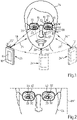
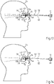
- the device 10 shown is designed as a smartphone, which contains an image capture device 12 with an objective lens system, which has an entrance aperture, and an image sensor.
- the device 10 contains a displaceable image acquisition device and image data is transmitted to a stationary computer unit for executing image processing routines via a cable or radio connection.
- the local refractive power of a left spectacle lens 18 and a right spectacle lens 20 in a spectacle frame 22, which is placed on the head 24 of a spectacle wearer can be measured at a large number of different points 16, 16', 16".
- the device 10 enables thus measuring the refractive power distribution of the left and right spectacle lens 18, 20.
- the device 10 can be designed as an alternative to a smartphone, in particular as a tablet computer with an image acquisition device or as a digital camera with a computer unit.
- the head 24 of the spectacle wearer is in a first step by means of the image acquisition device 12 of the device 10 from different Recording positions 26, 26', 26" are detected in order to obtain different first images 39, 39', 39" with an image of the front eye segment 28 of the left eye 30 with an extended structure 33 having a plurality of structure points 32 in it, the left eye 30 of the spectacle wearer has a viewing direction 34, 34', 34" pointing towards the recording position 26, 26', 26" of the image capturing device, which, if possible, passes through an entrance diaphragm in the image capturing device 12.
- the head 24 of the spectacle wearer is captured by the image capture device 12 of the device 10 from different recording positions 26, 26', 26" in order to also obtain different first images 39, 39 ', 39" with an image of the front eye section 28 of the right eye 36 with a structure 33 having a plurality of structure points 32 in it, with the right eye 36 of the spectacle wearer each having a pointing to the recording position 26, 26', 26" of the image acquisition device 12 line of sight 38, 38', 38" which, if possible, passes through the entrance aperture in the image acquisition device 12.
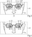
- the 2 shows the first image 39 of a section of the head 24 of the spectacle wearer with the spectacle frame 22 and with an image of a front eye section 28 of the left eye 30 with the structure points 32 of the structure 33, captured by the image acquisition device 12 in the device 10 from the acquisition position 26, the Iris, therein and with an image of a front eye segment 28 of the right eye 36 with a structure 33, the pupil, with several structure points 32.
- the 3 is the first image 39' of the section of the head 24 of the spectacle wearer with the spectacle frame 22 and with an image of the front eye section 28 of the left eye 30 with the structure 33 with structure points 32, captured by the image acquisition device 12 in the device 10 from the acquisition position 26' can be seen therein and with an image of an anterior eye segment 28 of the right eye 36 with the structure points 32 and the structure 33 .
- the 4 shows the image capture device 12 in the device 10 from the recording position 26" captured first image 39" of the section of the head 24 of the spectacle wearer with the spectacle frame 22 and with an image of the front eye section 28 of the left eye 30 with the structure 33 with structure points 32 therein and with an image of the front eye section 28 of the right eye 36 with the structure 33 and structure points 32.
- the first images 39, 39', 39" shown there not only each contain an image of the front eye segment 28 of the left eye 30 with at least one structure point 32 in it and an image of the right eye 36 with a structure point 32 in it at a Viewing direction, which the entrance aperture of the image acquisition device 12 in the in the 1 shown different recording positions 26, 26' and 26" interspersed, but also images of a respective same section 23 of the spectacle frame 22 and an image of the pupil 42 of the left eye 30 and an image of the pupil 44 of the right eye 36.
- a second step which can be before or after the first step, the head 24 of the spectacle wearer, as in FIG figure 5 without seeing the spectacle frame 22 by means of the image acquisition device 12 of the device 10 from other different recording positions 26, 26', 26'', which can be different from the recording positions for recording the head of the spectacle wearer with the spectacle frame, in order to thus have different second Images 41, 41', 41'' with an image of the front eye segment 28 of the left eye 30 with the structure 33 and the structure points 32 therein.
- the line of sight 34 of the left eye 30 of the spectacle wearer is in turn directed towards an entrance aperture of the image capturing device 12 of the device 10 .
- the head 24 of the spectacle wearer is captured by the image acquisition device 12 of the device 10 from different recording positions 26, 26', 26" in order to also use different second images 41, 41', 41" with an image of the front eye section 28 of the right eye 36 with the structure 33 and the structure points 32 therein.
- the viewing direction 38 of the right eye 36 of the spectacle wearer is in turn on an entrance aperture of the image capturing device 12 of the device 10 is directed.
- the 6 shows the second image 41 of a section of the head 24 of the spectacle wearer without the spectacle frame 22 and with an image of a front eye section 28 of the left eye 30 with the structure 33 and the structure points 32 and with an image of a front eye segment 28 of the right eye 36 with the structure 33 and the structure points 32.
- the 8 shows the second image 41" of the section of the head 24 of the spectacle wearer without the spectacle frame 22 and with an image of the front eye section 28 of the left eye 30 with the structure 33 and the structure points 32, captured by the image acquisition device 12 in the device 10 from the acquisition position 26". and with an image of a front eye segment 28 of the right eye 36 with the structure 33 and the structure points 32.
- the 10 shows a by means of the image acquisition device 12 in the device 10 from in FIG 9 marked recording position 26 captured second image 41 of a portion of the head 24 of the spectacle wearer without spectacle frame 22.
- the 11 is a means of the image acquisition device 12 in the device 10 from the in the 9 second image 41 ′ of a section of the head 24 of the spectacle wearer without the spectacle frame 22 can be seen in the recording position 26 ′ that has been identified.
- the 12 shows a by means of the image acquisition device 12 in the device 10 from in FIG 9 second image 41" of a section of the head 24 of the spectacle wearer without the spectacle frame 22 is captured in the recording position 26" that has been identified.
- the second images 41, 41', 41" shown contain not only an image of the front eye section 28 of the left eye 30 with the structure 33 and the structure points 32 and an image of the front eye section 28 of the right eye 36 with the structure 33 and the structure points 32 to those in the figure 5 or the 9 shown different recording positions 26, 26', 26" of the image acquisition device 12, but in addition to an image of the pupil 42 of the left eye 30 and an image of the pupil 44 of the right eye 36 also a structure point 32 of the head 24 of the spectacle wearer in the form of a point on the tip of the nose, whose position in a coordinate system 25 that is stationary relative to the head 24 of the spectacle wearer - unlike the position of the structural points 32 in the front eye section 28 of the left and right eyes 30, 36, which generally depends on the respective viewing direction - basically depends on the viewing direction 34, 34', 34" of the left eye 30 and of the viewing direction 38, 38', 38" of the right eye 36.
- a point whose position in a coordinate system 25 that is stationary relative to the head 24 of the spectacle wearer is generally independent of the line of sight 34, 34', 34", 38, 38', 38" of the left and right eyes 30, 36 can, however, e.g . B. also be a point of a nostril of the nose or a point of an eyebrow.
- the 13 shows the head 24 of the spectacle wearer with the left eye 30 and its eye rotation point 45 and the left spectacle lens 18 and the image acquisition device 12.
- the head 24 of the spectacle wearer with the right eye 36 and its eye rotation point 47 as well as the right spectacle lens 20 and the image capturing device 12 can be seen.
- the left and right eye 30, 36 is acquired through the left and right spectacle lens 18, 20 as the image of an apparent left or right eye 30', 36', which depends on the dioptric properties of the left or right Spectacle lens 18, 20 is larger or smaller than the left or right eye 30, 36 and which is away from this.
- first images 39, 39', 39", as shown in FIG Figures 2 to 4 are shown and contain identical sections of the spectacle frame 22, spectacle frame information data is calculated by means of image analysis, which includes information from the group of position, location, shape and coordinates of the spectacle frame 22 in a coordinate system 25' that is stationary with respect to the spectacle frame.
- the computing unit 14 of the device 10 calculates the coordinates of the structure points 32 of the front eye section 28 of the left eye 30 and the coordinates of the structure points 32 of the front eye section 28 of the right eye 36 by means of image evaluation. Based on the distances between structure points 32, the size of structures, e.g. B. the iris, in the front eye segment 28 of the left and right eye 30, 36 are determined. The local refractive power can be deduced from the ratios of the sizes of the structures observed through the spectacle lens in the first images to the real sizes of the structures calculated from the second images.
- the coordinates of the eye rotation point 45 of the left eye 30 and the eye rotation point 47 of the right eye 36 are calculated in the computer unit 14 from an assumed eye diameter D L for the left eye 30 and from an assumed eye diameter D R for the right eye 36 as well as from the Coordinates to structural points 32 of the head 24 are calculated, the coordinates of which are calculated from at least two images from a group of at least two first images 39, 39', 39", 39′′′, as shown in FIG Figures 2 to 4 are shown, and at least two second images 41, 41', 41", as shown in Figs Figures 6 to 8 and 10 to 12 are shown can be determined.
- the eye rotation point 45 of the left eye 30 and the eye rotation point 47 of the right eye 36 are determined from known information about the position of the left and right eyes 30, 36 in the head 24 of the spectacle wearer using coordinates to structural points 32 of the head 24, e.g. B. the tip of the nose, and an assumed, z. B. standardized value for the eye diameter D L of the left eye 30 and an assumed value for the eye diameter D R of the right eye 36 is determined.
- the eye diameter D L , D R of the left and right eyes 30, 36 of a person is fundamentally dependent on their gender and their age. It turns out that the assumption of an eye diameter DL ,R with 22 mm ⁇ DL ,R ⁇ 23 mm is a good estimate for the actual size of an eye diameter.
- the coordinates of structural points 32 of the front eye segment 28 of the left eye 30 and of the right eye 36 are determined in the computer unit 14 of the device 10 from the recorded second images 41, 41', 41" of the head 24 of the spectacle wearer without the spectacle frame 22, as in the Figures 6 to 8 and 10 to 12 are shown, calculated by detecting the image of one and the same structure point 32 in different images 41, 41', 41" using a feature matching method and then triangulating using known intrinsic and extrinsic parameters of the image acquisition device 12.
- These intrinsic and extrinsic parameters of the image acquisition device 12 are stored in a data memory of the computer unit 14. They can be determined, for example, by means of a camera calibration method or also by means of a SLAM method. It should be noted that so-called depth estimation methods and 3D reconstruction methods are used for this triangulation can come.
- the pupil center 31 of the pupil 42 of the left eye 30 in this image is first determined for the corresponding first image 39, 39', 39" by means of image evaluation. This can be done, for example, in an algorithm based on a segmentation of the front eye segment 28 of the left Eye 30, in which dark ellipses are detected within this front eye section 28, the geometric focus of which is assumed to be the sought-after pupil center 31. It should be noted that this determination of the pupil center does not necessarily have to be carried out in a computer unit, but in principle also manually by a person can take place, which applies the method for measuring the local refractive power or the refractive power distribution of a left and/or a right spectacle lens.
- the associated chief ray 50 of the imaging beam path 52 can be determined, with which the pupil center 31 of the pupil 42 of the left eye 30 through the left spectacle lens 18 into the image plane 48 of the Image acquisition device 12 is imaged.
- This main ray 50 is refracted by the left spectacle lens 18 .
- the visual point 54 at which the main ray 50 passes through the left-hand spectacle lens 18 on the side facing away from the spectacle wearer can then, taking into account the spectacle frame information data determined as described above, i.e.
- the coordinates of the spectacle frame 22 on the head 24 of the spectacle wearer as the point of intersection of the principal ray 50 with the left spectacle lens 18, ie as the visual point (x,y) of the left eye 30 through the left spectacle lens 18, can be calculated. From this, an assumed viewing direction 134 of the left eye 30 of the spectacle wearer can be determined, which corresponds to a vector pointing from the eye rotation point 45 of the left eye 30 in the direction of the visual point 54 on the left spectacle lens 18 . The point of intersection of this vector with a sphere around the eye rotation center 45 of the left eye 30, the diameter of which corresponds to the eye diameter D L , then results in the pupil center 31 of the pupil 42 of the left eye 30.
- the pupil center 37 of the pupil 44 of the right eye 36 in this image is first determined for the corresponding first image 39, 39', 39" by means of image evaluation. This can in turn be done by means of the algorithm specified above or by hand Based on the knowledge of the intrinsic and extrinsic parameters of the image capturing device 12 when capturing an image 39, 39', 39'', it is then also possible here to proceed to that in FIG 3 shown assumed pupillary center 37 of the pupil 44 of the right eye 36 in the image plane 48 of the image capturing device 12, the associated principal ray 50 of the imaging beam path 52 can be determined, with which the pupil center 37 of the pupil 44 of the right eye 36 is imaged through the right spectacle lens 20 into the image plane 48 of the image capturing device 12 .
- This main ray 50 is refracted by the right spectacle lens 20 .
- the location of the refraction of this main ray 50 on the right spectacle lens 20 can then in turn be determined as the intersection of the main ray 50 with the right spectacle lens 20, taking into account the spectacle frame information data determined as described above, i.e. taking into account the coordinates of the spectacle frame 22 on the head 24 of the spectacle wearer , ie as the viewing point (x,y) through the right lens 20 can be calculated.
- an assumed viewing direction 136 of the right eye 36 of the spectacle wearer can be determined, which corresponds to a vector emanating from the eye rotation point 47 of the right eye 36 and pointing in the direction of the visual point 54 on the right spectacle lens 20 .
- the point of intersection of this vector with a sphere around the eye rotation center 47 of the right eye 36, the diameter of which corresponds to the eye diameter D R then results in the Fig.3 shown pupil center 37 of the pupil 44 of the right eye 36.
- the size of the apparent structures 33 observed through the left-hand spectacle lens 18, 20 is determined as follows using a first image 39, 39', 39'': for each structure point 32 in these images, the intrinsic and extrinsic parameters of the image acquisition device are used 12 the associated principal ray 50 is calculated and its point of intersection with the left spectacle lens 18 is determined. From these intersections and their distances from one another can then be used to determine the apparent sizes of the structure 33 when observed through the left-hand spectacle lens 18 .
- the local refractive power at visual point 54 of left-hand spectacle lens 18 can then be specified from the ratio of the real to the apparent sizes.
- sizes of the structures 33 therein are determined using the coordinates of these structure points 32 previously calculated from the second images 41, 41', 41" and their distances from one another, e.g diameter of the iris.
- the size of the apparent structures 33 observed through the right spectacle lens 20 is determined using a first image 39, 39', 39" as follows: for each structure point 32 in these images, the intrinsic and extrinsic parameters of the image acquisition device 12 the associated principal ray 50 is calculated and its point of intersection with the right spectacle lens 20 is determined. The apparent sizes of the structure 33 when observed through the right spectacle lens 20 can then be determined from these points of intersection and their distances from one another.
- the refractive power of the left or right spectacle lens 18, 20 at the points traversed by the assumed viewing direction 134, 136 is obtained by evaluating the imaging equations.
- the local prismatic power can in principle also be determined using an offset of the front eye section in the image of the left eye.
- the 15 explains the calculation of imaging beam paths for structural points 32 of a structure 33 whose images are in images captured by the image capturing device 12 .
- a principal ray 50 of the imaging beam path 52 which passes through a spectacle lens 18, 20 of the spectacles with a known position and location in the coordinate system 25" of the image acquisition device 12, is then calculated from each imaged structure point 32, corresponding to the recording position 26 of the image acquisition device 12. From this and from From the previously determined coordinates of the different structure points 32 of the eye section 28 of the left eye 30 or of the right eye 36, a ray model then results which, for each structure point 32, deflects the associated one at the visual point 54 from the left or right spectacle lens 18, 20
- the imaging beam path 52 contains the prismatic effect of the corresponding left or right spectacle lens 18, 20 can be calculated from this.
- the computer unit 14 can then determine a distribution of the refractive power k(x,y) over the spectacle lens 18, 20.
- the accuracy of the calculation of the local refractive power k(x,y) of the left and right spectacle lens 18, 20 can be increased in particular by using a large number of different structure points 32 in the front eye section 28 of the left and right eye 30, 36 of a spectacle wearer can be detected and evaluated in a plurality of first and second images of the head 24 of the spectacle wearer.
Landscapes
- Physics & Mathematics (AREA)
- Health & Medical Sciences (AREA)
- Ophthalmology & Optometry (AREA)
- General Physics & Mathematics (AREA)
- Optics & Photonics (AREA)
- General Health & Medical Sciences (AREA)
- Chemical & Material Sciences (AREA)
- Analytical Chemistry (AREA)
- Geometry (AREA)
- Eyeglasses (AREA)
- Testing Of Optical Devices Or Fibers (AREA)
- Eye Examination Apparatus (AREA)
Claims (15)
- Procédé de mesure de la vergence locale d'un verre de lunettes gauche et/ou droit (18, 20) situé dans une monture de lunettes (22) en position de port sur une tête (24) d'un porteur de lunettes,
caractérisé par
une étape d'acquisition d'au moins deux premières reproductions depuis différentes positions de capture (26, 26', 26") par rapport à la tête (24), les au moins deux premières reproductions (39, 39', 39") contenant chacune :une image i) d'une portion d'œil avant (28) d'un œil gauche (30) ou ii) d'une portion d'œil avant (28) d'un œil gauche (30) et d'une partie du visage à chaque fois avec au moins deux points de structure (32) espacés l'un de l'autre et au moins une portion de la monture de lunettes (22) en position de port à l'intérieur, l'œil gauche (30) ayant à chaque fois une direction de vision (34, 34', 34") dirigée vers la position de capture (26, 26', 26") et un trajet de faisceau de reproduction (52), qui reproduit les au moins deux points de structure (32), passant à travers le verre de lunettes gauche (18), et/ou en variante une image i) d'une portion d'œil avant (28) d'un œil droit (36) ou ii) d'une portion d'œil avant (28) d'un œil droit (36) et d'une partie du visage à chaque fois avec au moins deux points de structure (32) espacés l'un de l'autre et au moins une portion de la monture de lunettes (22) en position de port à l'intérieur, l'œil droit (36) ayant une direction de vision (38, 38', 38") dirigée vers la position de capture (26, 26', 26") et un trajet de faisceau de reproduction (52), qui reproduit les au moins deux points de structure (32), passant à travers le verre de lunettes droit (20),une étape d'acquisition d'au moins deux deuxièmes reproductions (41, 41', 41") depuis différentes positions de capture (26, 26', 26") par rapport à la tête (24), les au moins deux deuxièmes reproductions (41, 41', 41") contenant chacune :une image des au moins deux points de structure (32) espacés l'un de l'autre i) de la portion d'œil avant (28) de l'œil gauche (30) ou ii) de la portion d'œil avant (28) de l'œil gauche (30) et de la partie du visage sans la monture de lunettes (22), contenant le verre de lunettes gauche (18), et/ou en variante une image des au moins deux points de structure (32) i) de la portion d'œil avant (28) de l'œil droit (36) ou ii) de la portion d'œil avant (28) de l'œil droit (36) et de la partie du visage sans la monture de lunettes (22), contenant le verre de lunettes droit (20) ;une étape de calcul des coordonnées des au moins deux points de structure (32) i) de la portion d'œil avant (28) de l'œil gauche (30) ou ii) de la portion d'œil avant (28) de l'œil gauche et de la partie du visage et/ou des au moins deux points de structure (32) i) de la portion d'œil avant (28) de l'œil droit (36) ou ii) de la portion d'œil avant (28) de l'œil droit (36) et de la partie du visage des au moins deux deuxièmes reproductions (41, 41', 41") dans un système de coordonnées (25"), qui est référencé à un système de coordonnées (25) qui est fixe par rapport à la tête (24) du porteur de lunettes, au moyen d'une évaluation d'image par triangulation ;une étape de détermination du point d'observation (54) à travers le verre de lunettes gauche (18) à partir d'au moins une première reproduction (39, 39', 39"), à chaque fois à partir d'un centre d'une structure d'image (33) du groupe comprenant une image de pupille, une image d'iris et des données d'information de monture de lunettes, ledit centre étant déterminé à partir de l'image d'une portion d'œil avant (28) de l'œil gauche (30) au moyen d'une évaluation d'image et/ou de détermination du point d'observation (54) à travers le verre de lunettes droit (20) à partir d'au moins une première reproduction (39, 39', 39"), à chaque fois à partir d'un centre d'une structure d'image (33) du groupe comprenant une image de pupille, une image d'iris et des données d'information de monture de lunettes, ledit centre étant déterminé à partir de l'image d'une portion d'œil avant (28) de l'œil droit (36) au moyen d'une évaluation d'image ; les données d'informations de monture de lunettes, comprenant des informations du groupe comprenant la position, l'emplacement, la forme et les coordonnées de la monture de lunettes (22) étant calculées à partir d'au moins deux reproductions, contenant une portion identique de la monture de lunettes (22), du groupe des au moins deux premières reproductions (39, 39', 39"), au moyen d'une évaluation d'image par triangulation dans un système de coordonnées (25") qui est référencé par rapport à un système de coordonnées (25) fixe par rapport à la tête (24) du porteur de lunettes ; etune étape de détermination d'une puissance dioptrique locale du verre de lunettes gauche (18) au point d'observation (54), étape dans laquelle à partir des coordonnées des au moins deux points de structure (32) i) de la portion d'œil avant (28) de l'œil gauche (30) ou ii) de la portion d'œil avant (28) de l'œil gauche (30) et de la partie du visage, lesdites coordonnées étant calculées à partir des au moins deux deuxièmes reproductions (41, 41', 41"), ainsi qu'à partir des au moins deux premières reproductions (39, 39', 39") comprenant des images des au moins deux points de structure (32), la vergence locale k(x,y) du verre de lunettes gauche (18) au point d'observation (54) est déterminée à partir d'un rapport d'une dimension d'une structure, déterminée à l'aide des au moins deux points de structure (32), dans au moins une des au moins deux premières reproductions (39, 39', 39") à la dimension de cette structure dans au moins une des au moins deux deuxièmes reproductions (41, 41', 41") ; et/ou une puissance dioptrique locale du verre de lunettes droit (20) au point d'observation (54) auquel, à partir des coordonnées des au moins deux points de structure (32) (i) de la portion d'œil avant (28) de l'œil droit (36) ou ii) de la portion d'œil avant (28) de l'œil droit (36) et de la partie du visage, lesdites coordonnées étant calculées à partir des au moins deux deuxièmes reproductions (41, 41', 41"), ainsi qu'à partir d'au moins deux premières reproductions (39, 39', 39") comprenant des images des au moins deux points de structure (32), la vergence locale k(x,y) du verre de lunettes droit (20) au point d'observation (54) est déterminée à partir d'un rapport d'une dimension d'une structure, déterminée à l'aide des au moins deux points de structure (32) dans au moins une des au moins deux premières reproductions (39, 39', 39") à la dimension de cette structure dans au moins une des au moins deux deuxièmes reproductions (41, 41', 41"). - Procédé selon la revendication 1, caractérisé en ce qu'à l'étape de détermination d'une puissance dioptrique locale du verre de lunettes gauche (18) au point d'observation (54), la puissance prismatique locale est déterminée à l'aide des coordonnées d'un point de rotation d'œil (40) ou à l'aide d'un décalage de la portion d'œil avant (28) dans l'image de l'œil gauche (30) et/ou, à l'étape de détermination d'une puissance dioptrique locale du verre de lunettes droit (20) au point d'observation (54), la puissance prismatique locale est déterminée à l'aide des coordonnées d'un point de rotation d'œil (40) ou d'un décalage de la portion d'œil avant (28) dans l'image de l'œil droit (36), les coordonnées du point de rotation d'œil (45) de l'œil gauche (30) et/ou du point de rotation d'œil (47) de l'œil droit (36) étant déterminées à partir d'un diamètre d'œil DL supposé pour l'œil gauche (30) et/ou à partir d'un diamètre DR supposé pour l'œil droit (36) et à partir de coordonnées d'au moins un point de structure (32) de la tête (24) dans un système de coordonnées (25"), qui est référencé par rapport à un système de coordonnées (25) fixe par rapport à la tête (24) du porteur de lunettes, ces coordonnées étant déterminées à partir d'au moins deux reproductions du groupe des au moins deux premières reproductions (39, 39', 39") et des au moins deux deuxièmes reproductions (41, 41', 41") ;
et/ou
caractérisé en ce que les premières reproductions (39, 39', 39") et les au moins deux deuxièmes reproductions (41, 41', 41") sont acquises au moyen d'au moins une installation d'acquisition d'images (12) qui est déplacée par rapport à la tête (24) du porteur de lunettes par déplacement de l'installation d'acquisition d'images (12) et/ou de la tête (24) du porteur de lunettes. - Procédé selon la revendication 2, caractérisé en ce que l'au moins une installation d'acquisition d'images (12) est tenu à la main et/ou en ce qu'un algorithme SLAM est utilisé pour déterminer des paramètres extrinsèques de l'au moins une installation d'acquisition d'images (12), incluant la position et l'emplacement celui-ci dans l'espace lors de la capture des premières reproductions (39, 39', 39") et/ou des deuxièmes reproductions (41, 41', 41").
- Procédé selon la revendication 2 ou 3, caractérisé en ce qu'un algorithme SLAM est utilisé pour calculer des paramètres intrinsèques de l'installation d'acquisition d'images (12).
- Procédé selon la revendication 4, caractérisé par des paramètres intrinsèques du groupe comprenant la distance focale, le centre d'image, les paramètres de cisaillement, les paramètres d'échelle, les paramètres de distorsion.
- Procédé selon l'une des revendications 1 à 5, caractérisé en ce qu'un procédé de détection de caractéristiques destiné à détecter les images de points de structure appropriés (32) et un procédé de mise en correspondance de caractéristiques destiné à détecter l'image de points de structure correspondants (32) dans les premières reproductions (39, 39', 39") et/ou les au moins deux deuxièmes reproductions (41, 41', 41") sont utilisés pour calculer les coordonnées des au moins deux points de structure (32) et/ou pour calculer la vergence à partir des points de structure (32) des premières reproductions (39, 39', 39").
- Procédé selon la revendication 6, caractérisé en ce que la vergence locale du verre de lunettes gauche (18) est calculée au moyen d'un procédé d'optimisation à partir de la dérivation d'un champ de gradient, qui est déterminé à partir de la déviation du trajet de faisceau de reproduction (52) pour l'image du centre d'une structure d'image (33) du groupe comprenant une image de pupille, une image d'iris de la portion d'œil avant (28) de l'œil gauche (30) à travers le verre de lunettes gauche (18) de la monture de lunettes (22) ; et/ou en ce que la vergence locale du verre de lunettes droit (20) est calculée au moyen d'un procédé d'optimisation à partir de la dérivation d'un champ de gradient, qui est déterminé à partir de la déviation du trajet de faisceau de reproduction (52) pour l'image du centre d'une structure d'image (33) du groupe comprenant une image de pupille, une image d'iris de la portion d'œil avant (28) de l'œil droit (36) à travers le verre de lunettes droit (20) de la monture de lunettes (22).
- Procédé selon l'une des revendications 1 à 7, caractérisé en ce que la puissance dioptrique du verre de lunettes gauche et/ou droit (18, 20) au point d'observation (54) est déterminée à partir d'une différence de forme et/ou d'une différence de dimension d'images des structures (33), comportant les au moins deux points de structure (32), dans les premières reproductions (39, 39', 39") et/ou les au moins deux deuxièmes reproductions (41, 41', 41").
- Procédé de mesure de la distribution de vergence d'un verre de lunettes gauche et/ou droit (18, 20) dans une monture de lunettes (22), procédé dans lequel une vergence locale du verre de lunettes gauche et/ou droit (18, 20) est mesurée dans un grand nombre de positions différentes du verre de lunettes gauche et/ou droit (18, 20) selon l'une des revendications 1 à 8.
- Procédé selon l'une des revendications 1 à 9, caractérisé en ce que les au moins deux points de structure identiques (32) espacés l'un de l'autre sont acquis dans les premières reproductions et dans les au moins deux deuxièmes reproductions.
- Progiciel comprenant un logiciel comprenant un code de programme destiné à réaliser toutes les étapes de procédé qui sont indiquées dans l'une des revendications 1 à 10 lorsque le logiciel est chargé dans une unité informatique (14) et/ou est exécuté dans une unité informatique (14).
- Support de stockage lisible par ordinateur comprenant des instructions qui, lorsqu'elles sont exécutées par un ordinateur, ordonnent à celui-ci d'exécuter toutes les étapes de procédé qui sont indiquées dans l'une des revendications 1 à 10.
- Support de données lisible par ordinateur sur lequel est stocké le logiciel du progiciel selon la revendication 11.
- Signal de support de données qui transmet le logiciel du progiciel selon la revendication 11.
- Dispositif de mesure de la vergence locale d'un verre de lunettes gauche et/ou droit (18, 20) dans une monture de lunettes (22), ledit dispositif comprenant une installation d'acquisition d'images (12) et une unité informatique (14) dans laquelle est chargé un logiciel comprenant un code de programme destiné à exécuter toutes les étapes de procédé qui sont indiquées dans l'une des revendications 1 à 10.
Applications Claiming Priority (2)
| Application Number | Priority Date | Filing Date | Title |
|---|---|---|---|
| EP19170714.0A EP3730918A1 (fr) | 2019-04-23 | 2019-04-23 | Procédé et dispositif de mesure de la force de rupture locale et / ou de la répartition de la force de rupture d'un verre de lunettes |
| PCT/EP2020/061258 WO2020216810A1 (fr) | 2019-04-23 | 2020-04-22 | Procédé et dispositif pour la mesure de la puissance optique locale et/ou de la distribution de puissance optique d'un verre de lunettes |
Publications (2)
| Publication Number | Publication Date |
|---|---|
| EP3924710A1 EP3924710A1 (fr) | 2021-12-22 |
| EP3924710B1 true EP3924710B1 (fr) | 2022-10-05 |
Family
ID=66251605
Family Applications (2)
| Application Number | Title | Priority Date | Filing Date |
|---|---|---|---|
| EP19170714.0A Withdrawn EP3730918A1 (fr) | 2019-04-23 | 2019-04-23 | Procédé et dispositif de mesure de la force de rupture locale et / ou de la répartition de la force de rupture d'un verre de lunettes |
| EP20719649.4A Active EP3924710B1 (fr) | 2019-04-23 | 2020-04-22 | Procédé et dispositif de mesure de la force de rupture locale et / ou de la répartition de la force de rupture d'un verre de lunettes |
Family Applications Before (1)
| Application Number | Title | Priority Date | Filing Date |
|---|---|---|---|
| EP19170714.0A Withdrawn EP3730918A1 (fr) | 2019-04-23 | 2019-04-23 | Procédé et dispositif de mesure de la force de rupture locale et / ou de la répartition de la force de rupture d'un verre de lunettes |
Country Status (5)
| Country | Link |
|---|---|
| US (1) | US11313759B2 (fr) |
| EP (2) | EP3730918A1 (fr) |
| CN (1) | CN113692527B (fr) |
| BR (1) | BR112021019374B1 (fr) |
| WO (1) | WO2020216810A1 (fr) |
Families Citing this family (9)
| Publication number | Priority date | Publication date | Assignee | Title |
|---|---|---|---|---|
| EP3730037A1 (fr) | 2019-04-23 | 2020-10-28 | Carl Zeiss Vision International GmbH | Détermination d'une erreur de réfection d'un il |
| EP3730919A1 (fr) | 2019-04-23 | 2020-10-28 | Carl Zeiss Vision International GmbH | Procédé et dispositif de mesure de la force de rupture locale ou de la distribution de la force de rupture d'un verre de lunettes |
| EP3730998A1 (fr) | 2019-04-23 | 2020-10-28 | Carl Zeiss Vision International GmbH | Détermination d'au moins un paramètre optique d'un verre de lunettes |
| GB202100314D0 (en) * | 2021-01-11 | 2021-02-24 | Cubitts Kx Ltd | Frame adjustment systems |
| EP4300173A1 (fr) | 2022-07-01 | 2024-01-03 | Carl Zeiss Vision International GmbH | Ensemble de données de représentation virtuelle d'un verre de lunettes et procédé et dispositif pour le générer |
| JP2024013947A (ja) * | 2022-07-21 | 2024-02-01 | キヤノン株式会社 | 撮像装置、撮像装置の撮像方法およびプログラム |
| EP4435402A1 (fr) * | 2023-03-23 | 2024-09-25 | Nokia Technologies Oy | Appareil et procédé de rendu de contenu visuel sur un écran d'affichage |
| CN116958885B (zh) * | 2023-09-19 | 2023-12-05 | 四川大学 | 一种基于阅读视野的矫正眼镜佩戴舒适度评价方法和系统 |
| SE2450553A1 (en) * | 2024-05-23 | 2025-11-24 | Tobii Ab | Estimating Prescription Glasses Strength for Head-Mounted Display Users |
Family Cites Families (13)
| Publication number | Priority date | Publication date | Assignee | Title |
|---|---|---|---|---|
| DE102008003906B4 (de) * | 2008-01-10 | 2009-11-26 | Rodenstock Gmbh | Verwendung eines Fixationstargets und Vorrichtung |
| BRPI1007210B1 (pt) * | 2009-01-30 | 2019-12-17 | Hoya Corp | método implementado por computador para projetar lente de óculos, método para fabricar lente de óculos, e, sistema para fabricar lente de óculos |
| FR2984565A1 (fr) * | 2011-12-19 | 2013-06-21 | Thomson Licensing | Procede et dispositif d'estimation de la puissance optique des lentilles de verres correcteurs d'une paire de lunettes portee par un spectateur. |
| JP6307805B2 (ja) | 2013-07-24 | 2018-04-11 | 富士通株式会社 | 画像処理装置、電子機器、眼鏡特性判定方法および眼鏡特性判定プログラム |
| KR101528132B1 (ko) * | 2014-11-13 | 2015-06-12 | 윤철주 | 모바일 디바이스를 이용한 안경렌즈의 도수 측정방법 |
| DE102015211879B4 (de) | 2015-06-25 | 2018-10-18 | Carl Zeiss Ag | Vermessen von individuellen Daten einer Brille |
| WO2017134275A1 (fr) * | 2016-02-05 | 2017-08-10 | Eidgenossische Technische Hochschule Zurich | Procédés et systèmes permettant de déterminer un axe optique et/ou des propriétés physiques d'une lentille, et leur utilisation dans l'imagerie virtuelle et des visiocasques |
| WO2017205903A1 (fr) * | 2016-06-01 | 2017-12-07 | Vidi Pty Ltd | Système optique de mesure et de balayage et procédés d'utilisation |
| US20210231974A1 (en) * | 2016-06-01 | 2021-07-29 | Vidi Pty Ltd | Optical measuring and scanning system and methods of use |
| EP3730998A1 (fr) | 2019-04-23 | 2020-10-28 | Carl Zeiss Vision International GmbH | Détermination d'au moins un paramètre optique d'un verre de lunettes |
| EP3730919A1 (fr) | 2019-04-23 | 2020-10-28 | Carl Zeiss Vision International GmbH | Procédé et dispositif de mesure de la force de rupture locale ou de la distribution de la force de rupture d'un verre de lunettes |
| EP3730037A1 (fr) | 2019-04-23 | 2020-10-28 | Carl Zeiss Vision International GmbH | Détermination d'une erreur de réfection d'un il |
| EP3730036A1 (fr) | 2019-04-23 | 2020-10-28 | Carl Zeiss Vision International GmbH | Détermination d'une erreur de réfection d'un il |
-
2019
- 2019-04-23 EP EP19170714.0A patent/EP3730918A1/fr not_active Withdrawn
-
2020
- 2020-04-22 CN CN202080030594.4A patent/CN113692527B/zh active Active
- 2020-04-22 BR BR112021019374-0A patent/BR112021019374B1/pt active IP Right Grant
- 2020-04-22 EP EP20719649.4A patent/EP3924710B1/fr active Active
- 2020-04-22 WO PCT/EP2020/061258 patent/WO2020216810A1/fr not_active Ceased
-
2021
- 2021-09-23 US US17/482,853 patent/US11313759B2/en active Active
Also Published As
| Publication number | Publication date |
|---|---|
| EP3924710A1 (fr) | 2021-12-22 |
| CN113692527B (zh) | 2022-11-11 |
| US20220003632A1 (en) | 2022-01-06 |
| BR112021019374A2 (fr) | 2021-12-07 |
| BR112021019374B1 (pt) | 2024-01-16 |
| WO2020216810A1 (fr) | 2020-10-29 |
| CN113692527A (zh) | 2021-11-23 |
| EP3730918A1 (fr) | 2020-10-28 |
| US11313759B2 (en) | 2022-04-26 |
Similar Documents
| Publication | Publication Date | Title |
|---|---|---|
| EP3924710B1 (fr) | Procédé et dispositif de mesure de la force de rupture locale et / ou de la répartition de la force de rupture d'un verre de lunettes | |
| EP3956721B1 (fr) | Détermination d'au moins un paramètre optique d'un verre de lunettes | |
| EP3959497B1 (fr) | Procédé et dispositif de mesure de la force de rupture locale ou de la distribution de la force de rupture d'un verre de lunettes | |
| EP3542211B2 (fr) | Procédé et dispositif ainsi que programme informatique destinés à déterminer une représentation d'un bord de verre de lunettes | |
| DE102016106121B4 (de) | Verfahren und Vorrichtung zum Bestimmen von Parametern zur Brillenanpassung | |
| EP3702832B1 (fr) | Procédé, dispositifs et programme informatique de détermination d'un point visuel proche | |
| EP3235422B1 (fr) | Procede et dispositif destines a la determination de la position du point rotatif oqulaire | |
| EP3955800B1 (fr) | Détermination d'une erreur de réfection d'un il | |
| EP3958726B1 (fr) | Détermination d'une erreur de réfection d'un il | |
| DE102011054833A1 (de) | Verfahren zum Messen der binokularen Sehleistung, Programm zum Messen der binokularen Sehleistung, Verfahren zum Entwerfen von Brillengläsern und Verfahren zur Herstellung von Brillengläsern | |
| EP3210071B1 (fr) | Dispositif et procédé de détermination de paramètres optiques | |
| EP3574370B1 (fr) | Procédé assisté par ordinateur destiné à déterminer une représentation d'un bord de monture de lunette ou d'une représentation des bords de verres de lunettes | |
| WO2020182867A1 (fr) | Procédé, dispositif de centrage et produit programme d'ordinateur permettant de mesurer la distance entre un utilisateur et un dispositif de centrage | |
| DE102019212653A1 (de) | Computerimplementiertes Verfahren zum Aufnehmen einer Blickrichtung eines Auges eines Brillenträgers sowie Brille | |
| DE102011009260A1 (de) | Verfahren und Vorrichtungen zur Bestimmung der Rotationsparameter der Augen |
Legal Events
| Date | Code | Title | Description |
|---|---|---|---|
| STAA | Information on the status of an ep patent application or granted ep patent |
Free format text: STATUS: UNKNOWN |
|
| STAA | Information on the status of an ep patent application or granted ep patent |
Free format text: STATUS: THE INTERNATIONAL PUBLICATION HAS BEEN MADE |
|
| PUAI | Public reference made under article 153(3) epc to a published international application that has entered the european phase |
Free format text: ORIGINAL CODE: 0009012 |
|
| STAA | Information on the status of an ep patent application or granted ep patent |
Free format text: STATUS: REQUEST FOR EXAMINATION WAS MADE |
|
| 17P | Request for examination filed |
Effective date: 20210913 |
|
| AK | Designated contracting states |
Kind code of ref document: A1 Designated state(s): AL AT BE BG CH CY CZ DE DK EE ES FI FR GB GR HR HU IE IS IT LI LT LU LV MC MK MT NL NO PL PT RO RS SE SI SK SM TR |
|
| STAA | Information on the status of an ep patent application or granted ep patent |
Free format text: STATUS: EXAMINATION IS IN PROGRESS |
|
| 17Q | First examination report despatched |
Effective date: 20220125 |
|
| GRAP | Despatch of communication of intention to grant a patent |
Free format text: ORIGINAL CODE: EPIDOSNIGR1 |
|
| STAA | Information on the status of an ep patent application or granted ep patent |
Free format text: STATUS: GRANT OF PATENT IS INTENDED |
|
| DAV | Request for validation of the european patent (deleted) | ||
| DAX | Request for extension of the european patent (deleted) | ||
| INTG | Intention to grant announced |
Effective date: 20220715 |
|
| GRAS | Grant fee paid |
Free format text: ORIGINAL CODE: EPIDOSNIGR3 |
|
| GRAA | (expected) grant |
Free format text: ORIGINAL CODE: 0009210 |
|
| STAA | Information on the status of an ep patent application or granted ep patent |
Free format text: STATUS: THE PATENT HAS BEEN GRANTED |
|
| AK | Designated contracting states |
Kind code of ref document: B1 Designated state(s): AL AT BE BG CH CY CZ DE DK EE ES FI FR GB GR HR HU IE IS IT LI LT LU LV MC MK MT NL NO PL PT RO RS SE SI SK SM TR |
|
| REG | Reference to a national code |
Ref country code: GB Ref legal event code: FG4D Free format text: NOT ENGLISH |
|
| REG | Reference to a national code |
Ref country code: CH Ref legal event code: EP |
|
| REG | Reference to a national code |
Ref country code: AT Ref legal event code: REF Ref document number: 1523014 Country of ref document: AT Kind code of ref document: T Effective date: 20221015 |
|
| REG | Reference to a national code |
Ref country code: DE Ref legal event code: R096 Ref document number: 502020001810 Country of ref document: DE |
|
| REG | Reference to a national code |
Ref country code: IE Ref legal event code: FG4D Free format text: LANGUAGE OF EP DOCUMENT: GERMAN |
|
| REG | Reference to a national code |
Ref country code: NL Ref legal event code: FP |
|
| REG | Reference to a national code |
Ref country code: LT Ref legal event code: MG9D |
|
| PG25 | Lapsed in a contracting state [announced via postgrant information from national office to epo] |
Ref country code: SE Free format text: LAPSE BECAUSE OF FAILURE TO SUBMIT A TRANSLATION OF THE DESCRIPTION OR TO PAY THE FEE WITHIN THE PRESCRIBED TIME-LIMIT Effective date: 20221005 Ref country code: PT Free format text: LAPSE BECAUSE OF FAILURE TO SUBMIT A TRANSLATION OF THE DESCRIPTION OR TO PAY THE FEE WITHIN THE PRESCRIBED TIME-LIMIT Effective date: 20230206 Ref country code: NO Free format text: LAPSE BECAUSE OF FAILURE TO SUBMIT A TRANSLATION OF THE DESCRIPTION OR TO PAY THE FEE WITHIN THE PRESCRIBED TIME-LIMIT Effective date: 20230105 Ref country code: LT Free format text: LAPSE BECAUSE OF FAILURE TO SUBMIT A TRANSLATION OF THE DESCRIPTION OR TO PAY THE FEE WITHIN THE PRESCRIBED TIME-LIMIT Effective date: 20221005 Ref country code: FI Free format text: LAPSE BECAUSE OF FAILURE TO SUBMIT A TRANSLATION OF THE DESCRIPTION OR TO PAY THE FEE WITHIN THE PRESCRIBED TIME-LIMIT Effective date: 20221005 Ref country code: ES Free format text: LAPSE BECAUSE OF FAILURE TO SUBMIT A TRANSLATION OF THE DESCRIPTION OR TO PAY THE FEE WITHIN THE PRESCRIBED TIME-LIMIT Effective date: 20221005 |
|
| PG25 | Lapsed in a contracting state [announced via postgrant information from national office to epo] |
Ref country code: RS Free format text: LAPSE BECAUSE OF FAILURE TO SUBMIT A TRANSLATION OF THE DESCRIPTION OR TO PAY THE FEE WITHIN THE PRESCRIBED TIME-LIMIT Effective date: 20221005 Ref country code: PL Free format text: LAPSE BECAUSE OF FAILURE TO SUBMIT A TRANSLATION OF THE DESCRIPTION OR TO PAY THE FEE WITHIN THE PRESCRIBED TIME-LIMIT Effective date: 20221005 Ref country code: LV Free format text: LAPSE BECAUSE OF FAILURE TO SUBMIT A TRANSLATION OF THE DESCRIPTION OR TO PAY THE FEE WITHIN THE PRESCRIBED TIME-LIMIT Effective date: 20221005 Ref country code: IS Free format text: LAPSE BECAUSE OF FAILURE TO SUBMIT A TRANSLATION OF THE DESCRIPTION OR TO PAY THE FEE WITHIN THE PRESCRIBED TIME-LIMIT Effective date: 20230205 Ref country code: HR Free format text: LAPSE BECAUSE OF FAILURE TO SUBMIT A TRANSLATION OF THE DESCRIPTION OR TO PAY THE FEE WITHIN THE PRESCRIBED TIME-LIMIT Effective date: 20221005 Ref country code: GR Free format text: LAPSE BECAUSE OF FAILURE TO SUBMIT A TRANSLATION OF THE DESCRIPTION OR TO PAY THE FEE WITHIN THE PRESCRIBED TIME-LIMIT Effective date: 20230106 |
|
| REG | Reference to a national code |
Ref country code: DE Ref legal event code: R097 Ref document number: 502020001810 Country of ref document: DE |
|
| PG25 | Lapsed in a contracting state [announced via postgrant information from national office to epo] |
Ref country code: SM Free format text: LAPSE BECAUSE OF FAILURE TO SUBMIT A TRANSLATION OF THE DESCRIPTION OR TO PAY THE FEE WITHIN THE PRESCRIBED TIME-LIMIT Effective date: 20221005 Ref country code: RO Free format text: LAPSE BECAUSE OF FAILURE TO SUBMIT A TRANSLATION OF THE DESCRIPTION OR TO PAY THE FEE WITHIN THE PRESCRIBED TIME-LIMIT Effective date: 20221005 Ref country code: EE Free format text: LAPSE BECAUSE OF FAILURE TO SUBMIT A TRANSLATION OF THE DESCRIPTION OR TO PAY THE FEE WITHIN THE PRESCRIBED TIME-LIMIT Effective date: 20221005 Ref country code: DK Free format text: LAPSE BECAUSE OF FAILURE TO SUBMIT A TRANSLATION OF THE DESCRIPTION OR TO PAY THE FEE WITHIN THE PRESCRIBED TIME-LIMIT Effective date: 20221005 Ref country code: CZ Free format text: LAPSE BECAUSE OF FAILURE TO SUBMIT A TRANSLATION OF THE DESCRIPTION OR TO PAY THE FEE WITHIN THE PRESCRIBED TIME-LIMIT Effective date: 20221005 |
|
| PLBE | No opposition filed within time limit |
Free format text: ORIGINAL CODE: 0009261 |
|
| STAA | Information on the status of an ep patent application or granted ep patent |
Free format text: STATUS: NO OPPOSITION FILED WITHIN TIME LIMIT |
|
| PG25 | Lapsed in a contracting state [announced via postgrant information from national office to epo] |
Ref country code: SK Free format text: LAPSE BECAUSE OF FAILURE TO SUBMIT A TRANSLATION OF THE DESCRIPTION OR TO PAY THE FEE WITHIN THE PRESCRIBED TIME-LIMIT Effective date: 20221005 Ref country code: AL Free format text: LAPSE BECAUSE OF FAILURE TO SUBMIT A TRANSLATION OF THE DESCRIPTION OR TO PAY THE FEE WITHIN THE PRESCRIBED TIME-LIMIT Effective date: 20221005 |
|
| 26N | No opposition filed |
Effective date: 20230706 |
|
| PG25 | Lapsed in a contracting state [announced via postgrant information from national office to epo] |
Ref country code: SI Free format text: LAPSE BECAUSE OF FAILURE TO SUBMIT A TRANSLATION OF THE DESCRIPTION OR TO PAY THE FEE WITHIN THE PRESCRIBED TIME-LIMIT Effective date: 20221005 |
|
| REG | Reference to a national code |
Ref country code: CH Ref legal event code: PL |
|
| PG25 | Lapsed in a contracting state [announced via postgrant information from national office to epo] |
Ref country code: LU Free format text: LAPSE BECAUSE OF NON-PAYMENT OF DUE FEES Effective date: 20230422 |
|
| REG | Reference to a national code |
Ref country code: BE Ref legal event code: MM Effective date: 20230430 |
|
| PG25 | Lapsed in a contracting state [announced via postgrant information from national office to epo] |
Ref country code: MC Free format text: LAPSE BECAUSE OF FAILURE TO SUBMIT A TRANSLATION OF THE DESCRIPTION OR TO PAY THE FEE WITHIN THE PRESCRIBED TIME-LIMIT Effective date: 20221005 |
|
| PG25 | Lapsed in a contracting state [announced via postgrant information from national office to epo] |
Ref country code: MC Free format text: LAPSE BECAUSE OF FAILURE TO SUBMIT A TRANSLATION OF THE DESCRIPTION OR TO PAY THE FEE WITHIN THE PRESCRIBED TIME-LIMIT Effective date: 20221005 Ref country code: LI Free format text: LAPSE BECAUSE OF NON-PAYMENT OF DUE FEES Effective date: 20230430 Ref country code: CH Free format text: LAPSE BECAUSE OF NON-PAYMENT OF DUE FEES Effective date: 20230430 |
|
| REG | Reference to a national code |
Ref country code: IE Ref legal event code: MM4A |
|
| PG25 | Lapsed in a contracting state [announced via postgrant information from national office to epo] |
Ref country code: BE Free format text: LAPSE BECAUSE OF NON-PAYMENT OF DUE FEES Effective date: 20230430 |
|
| PG25 | Lapsed in a contracting state [announced via postgrant information from national office to epo] |
Ref country code: IE Free format text: LAPSE BECAUSE OF NON-PAYMENT OF DUE FEES Effective date: 20230422 |
|
| PG25 | Lapsed in a contracting state [announced via postgrant information from national office to epo] |
Ref country code: IE Free format text: LAPSE BECAUSE OF NON-PAYMENT OF DUE FEES Effective date: 20230422 |
|
| PG25 | Lapsed in a contracting state [announced via postgrant information from national office to epo] |
Ref country code: BG Free format text: LAPSE BECAUSE OF FAILURE TO SUBMIT A TRANSLATION OF THE DESCRIPTION OR TO PAY THE FEE WITHIN THE PRESCRIBED TIME-LIMIT Effective date: 20221005 |
|
| PG25 | Lapsed in a contracting state [announced via postgrant information from national office to epo] |
Ref country code: BG Free format text: LAPSE BECAUSE OF FAILURE TO SUBMIT A TRANSLATION OF THE DESCRIPTION OR TO PAY THE FEE WITHIN THE PRESCRIBED TIME-LIMIT Effective date: 20221005 |
|
| GBPC | Gb: european patent ceased through non-payment of renewal fee |
Effective date: 20240422 |
|
| PG25 | Lapsed in a contracting state [announced via postgrant information from national office to epo] |
Ref country code: GB Free format text: LAPSE BECAUSE OF NON-PAYMENT OF DUE FEES Effective date: 20240422 |
|
| PG25 | Lapsed in a contracting state [announced via postgrant information from national office to epo] |
Ref country code: GB Free format text: LAPSE BECAUSE OF NON-PAYMENT OF DUE FEES Effective date: 20240422 |
|
| PGFP | Annual fee paid to national office [announced via postgrant information from national office to epo] |
Ref country code: NL Payment date: 20250418 Year of fee payment: 6 |
|
| PGFP | Annual fee paid to national office [announced via postgrant information from national office to epo] |
Ref country code: DE Payment date: 20250422 Year of fee payment: 6 |
|
| PGFP | Annual fee paid to national office [announced via postgrant information from national office to epo] |
Ref country code: IT Payment date: 20250424 Year of fee payment: 6 |
|
| PGFP | Annual fee paid to national office [announced via postgrant information from national office to epo] |
Ref country code: FR Payment date: 20250425 Year of fee payment: 6 |
|
| PGFP | Annual fee paid to national office [announced via postgrant information from national office to epo] |
Ref country code: AT Payment date: 20250721 Year of fee payment: 5 |
|
| PG25 | Lapsed in a contracting state [announced via postgrant information from national office to epo] |
Ref country code: CY Free format text: LAPSE BECAUSE OF FAILURE TO SUBMIT A TRANSLATION OF THE DESCRIPTION OR TO PAY THE FEE WITHIN THE PRESCRIBED TIME-LIMIT; INVALID AB INITIO Effective date: 20200422 |
|
| PG25 | Lapsed in a contracting state [announced via postgrant information from national office to epo] |
Ref country code: HU Free format text: LAPSE BECAUSE OF FAILURE TO SUBMIT A TRANSLATION OF THE DESCRIPTION OR TO PAY THE FEE WITHIN THE PRESCRIBED TIME-LIMIT; INVALID AB INITIO Effective date: 20200422 |
|
| PG25 | Lapsed in a contracting state [announced via postgrant information from national office to epo] |
Ref country code: TR Free format text: LAPSE BECAUSE OF FAILURE TO SUBMIT A TRANSLATION OF THE DESCRIPTION OR TO PAY THE FEE WITHIN THE PRESCRIBED TIME-LIMIT Effective date: 20221005 |