EP3924712B1 - Appareil médical de prélèvement et de préparation d'échantillons biologiques - Google Patents
Appareil médical de prélèvement et de préparation d'échantillons biologiques Download PDFInfo
- Publication number
- EP3924712B1 EP3924712B1 EP20755649.9A EP20755649A EP3924712B1 EP 3924712 B1 EP3924712 B1 EP 3924712B1 EP 20755649 A EP20755649 A EP 20755649A EP 3924712 B1 EP3924712 B1 EP 3924712B1
- Authority
- EP
- European Patent Office
- Prior art keywords
- elongated body
- medical apparatus
- cell block
- filter assembly
- distal end
- Prior art date
- Legal status (The legal status is an assumption and is not a legal conclusion. Google has not performed a legal analysis and makes no representation as to the accuracy of the status listed.)
- Active
Links
Images




Classifications
-
- G—PHYSICS
- G01—MEASURING; TESTING
- G01N—INVESTIGATING OR ANALYSING MATERIALS BY DETERMINING THEIR CHEMICAL OR PHYSICAL PROPERTIES
- G01N1/00—Sampling; Preparing specimens for investigation
- G01N1/28—Preparing specimens for investigation including physical details of (bio-)chemical methods covered elsewhere, e.g. G01N33/50, C12Q
- G01N1/40—Concentrating samples
- G01N1/4005—Concentrating samples by transferring a selected component through a membrane
-
- B—PERFORMING OPERATIONS; TRANSPORTING
- B01—PHYSICAL OR CHEMICAL PROCESSES OR APPARATUS IN GENERAL
- B01L—CHEMICAL OR PHYSICAL LABORATORY APPARATUS FOR GENERAL USE
- B01L3/00—Containers or dishes for laboratory use, e.g. laboratory glassware; Droppers
- B01L3/50—Containers for the purpose of retaining a material to be analysed, e.g. test tubes
- B01L3/502—Containers for the purpose of retaining a material to be analysed, e.g. test tubes with fluid transport, e.g. in multi-compartment structures
- B01L3/5021—Test tubes specially adapted for centrifugation purposes
-
- G—PHYSICS
- G01—MEASURING; TESTING
- G01N—INVESTIGATING OR ANALYSING MATERIALS BY DETERMINING THEIR CHEMICAL OR PHYSICAL PROPERTIES
- G01N1/00—Sampling; Preparing specimens for investigation
- G01N1/02—Devices for withdrawing samples
- G01N1/04—Devices for withdrawing samples in the solid state, e.g. by cutting
- G01N1/06—Devices for withdrawing samples in the solid state, e.g. by cutting providing a thin slice, e.g. microtome
-
- G—PHYSICS
- G01—MEASURING; TESTING
- G01N—INVESTIGATING OR ANALYSING MATERIALS BY DETERMINING THEIR CHEMICAL OR PHYSICAL PROPERTIES
- G01N1/00—Sampling; Preparing specimens for investigation
- G01N1/28—Preparing specimens for investigation including physical details of (bio-)chemical methods covered elsewhere, e.g. G01N33/50, C12Q
- G01N1/2813—Producing thin layers of samples on a substrate, e.g. smearing, spinning-on
-
- G—PHYSICS
- G01—MEASURING; TESTING
- G01N—INVESTIGATING OR ANALYSING MATERIALS BY DETERMINING THEIR CHEMICAL OR PHYSICAL PROPERTIES
- G01N1/00—Sampling; Preparing specimens for investigation
- G01N1/28—Preparing specimens for investigation including physical details of (bio-)chemical methods covered elsewhere, e.g. G01N33/50, C12Q
- G01N1/286—Preparing specimens for investigation including physical details of (bio-)chemical methods covered elsewhere, e.g. G01N33/50, C12Q involving mechanical work, e.g. chopping, disintegrating, compacting, homogenising
-
- G—PHYSICS
- G01—MEASURING; TESTING
- G01N—INVESTIGATING OR ANALYSING MATERIALS BY DETERMINING THEIR CHEMICAL OR PHYSICAL PROPERTIES
- G01N1/00—Sampling; Preparing specimens for investigation
- G01N1/28—Preparing specimens for investigation including physical details of (bio-)chemical methods covered elsewhere, e.g. G01N33/50, C12Q
- G01N1/30—Staining; Impregnating ; Fixation; Dehydration; Multistep processes for preparing samples of tissue, cell or nucleic acid material and the like for analysis
- G01N1/31—Apparatus therefor
-
- G—PHYSICS
- G01—MEASURING; TESTING
- G01N—INVESTIGATING OR ANALYSING MATERIALS BY DETERMINING THEIR CHEMICAL OR PHYSICAL PROPERTIES
- G01N1/00—Sampling; Preparing specimens for investigation
- G01N1/28—Preparing specimens for investigation including physical details of (bio-)chemical methods covered elsewhere, e.g. G01N33/50, C12Q
- G01N1/40—Concentrating samples
- G01N1/4077—Concentrating samples by other techniques involving separation of suspended solids
-
- A—HUMAN NECESSITIES
- A61—MEDICAL OR VETERINARY SCIENCE; HYGIENE
- A61B—DIAGNOSIS; SURGERY; IDENTIFICATION
- A61B10/00—Instruments for taking body samples for diagnostic purposes; Other methods or instruments for diagnosis, e.g. for vaccination diagnosis, sex determination or ovulation-period determination; Throat striking implements
- A61B10/0096—Casings for storing test samples
-
- B—PERFORMING OPERATIONS; TRANSPORTING
- B01—PHYSICAL OR CHEMICAL PROCESSES OR APPARATUS IN GENERAL
- B01L—CHEMICAL OR PHYSICAL LABORATORY APPARATUS FOR GENERAL USE
- B01L2300/00—Additional constructional details
- B01L2300/04—Closures and closing means
- B01L2300/041—Connecting closures to device or container
- B01L2300/042—Caps; Plugs
-
- B—PERFORMING OPERATIONS; TRANSPORTING
- B01—PHYSICAL OR CHEMICAL PROCESSES OR APPARATUS IN GENERAL
- B01L—CHEMICAL OR PHYSICAL LABORATORY APPARATUS FOR GENERAL USE
- B01L2300/00—Additional constructional details
- B01L2300/04—Closures and closing means
- B01L2300/041—Connecting closures to device or container
- B01L2300/044—Connecting closures to device or container pierceable, e.g. films, membranes
-
- B—PERFORMING OPERATIONS; TRANSPORTING
- B01—PHYSICAL OR CHEMICAL PROCESSES OR APPARATUS IN GENERAL
- B01L—CHEMICAL OR PHYSICAL LABORATORY APPARATUS FOR GENERAL USE
- B01L2300/00—Additional constructional details
- B01L2300/06—Auxiliary integrated devices, integrated components
- B01L2300/0681—Filter
-
- B—PERFORMING OPERATIONS; TRANSPORTING
- B01—PHYSICAL OR CHEMICAL PROCESSES OR APPARATUS IN GENERAL
- B01L—CHEMICAL OR PHYSICAL LABORATORY APPARATUS FOR GENERAL USE
- B01L2300/00—Additional constructional details
- B01L2300/08—Geometry, shape and general structure
- B01L2300/0848—Specific forms of parts of containers
- B01L2300/0851—Bottom walls
-
- C—CHEMISTRY; METALLURGY
- C12—BIOCHEMISTRY; BEER; SPIRITS; WINE; VINEGAR; MICROBIOLOGY; ENZYMOLOGY; MUTATION OR GENETIC ENGINEERING
- C12M—APPARATUS FOR ENZYMOLOGY OR MICROBIOLOGY; APPARATUS FOR CULTURING MICROORGANISMS FOR PRODUCING BIOMASS, FOR GROWING CELLS OR FOR OBTAINING FERMENTATION OR METABOLIC PRODUCTS, i.e. BIOREACTORS OR FERMENTERS
- C12M45/00—Means for pre-treatment of biological substances
- C12M45/22—Means for packing or storing viable microorganisms
-
- G—PHYSICS
- G01—MEASURING; TESTING
- G01N—INVESTIGATING OR ANALYSING MATERIALS BY DETERMINING THEIR CHEMICAL OR PHYSICAL PROPERTIES
- G01N1/00—Sampling; Preparing specimens for investigation
- G01N1/28—Preparing specimens for investigation including physical details of (bio-)chemical methods covered elsewhere, e.g. G01N33/50, C12Q
- G01N1/40—Concentrating samples
- G01N1/4077—Concentrating samples by other techniques involving separation of suspended solids
- G01N2001/4088—Concentrating samples by other techniques involving separation of suspended solids filtration
Definitions
- the disclosed subject matter relates to a system, apparatus and method for preparing cells and small tissue samples for diagnostic/research tests and procedures.
- MIP minimally invasive procedure
- FNA fine needle aspiration
- WO 2019/001228 A1 describes a fixed tube of a nucleic acid extraction component and a nucleic acid extraction component.
- the nucleic acid extraction component comprises a cylindrical membrane tube, which is fitted over the fixed tube;
- the fixed tube comprises a tube body, a tube opening, and a bottom;
- the tube body extends along a first direction;
- the end of the tube opening distal from the tube body is provided with a protrusion which protrudes along a second direction, the first direction being vertical to the second direction;
- the bottom and the tube opening are respectively connected to two opposite sides of the tube body;
- the bottom is provided with a shoulder; and the shoulder of the bottom is connected to the cylindrical membrane tube.
- WO 2013/059526 A1 describes a medical apparatus and method of preparing one or more cell blocks.
- the medical apparatus comprises at least one elongate tubular body having a proximal end and a distal end and a filter membrane disposed between the proximal end and a distal end of the elongate tubular body.
- the filter membrane which can include alignment features and structural features to engage the tubular body, and/or cover, is sectionable.
- a second elongate tubular body is provided which telescopingly receives at least a portion of the first elongate tubular body.
- a support member is provided for engaging the filter membrane and positioning the filter membrane at a midpoint of the elongate tubular body during centrifuging.
- the invention relates to a medical apparatus as defined in claim 1. Further embodiments of the invention are defined in the dependent claims.
- the invention relates to a medical apparatus including an elongated body and defining a loading chamber between a proximal end and a distal end thereof for storing a liquid therein, the elongated body defining an outlet at the distal end thereof; a cell block filter assembly including a cell block body and defining a well portion matingly engageable with the distal end of the elongated body for receiving fluid from the outlet of the elongated body and defining a well opening on a bottom thereof; a filter membrane disposed across the well opening on the bottom of the well portion; and a cover member positionable over the well portion wherein the entire cell block filter assembly is sliceable into slices having a thickness suitable for mounting on a laboratory slide.
- the medical apparatus further includes a base member for securing the cell block filter assembly at the distal end of the elongate portion, and wherein the outer surface of the distal end of the elongate body is configured to engage with the base member, wherein the base member prevents the passage of fluid out of the filter assembly.
- the base member can be secured to the elongate body with threaded engagement or a ratchet engagement.
- the cell block body is fabricated substantially from LLDPE.
- the cover can fabricated substantially from LLDPE.
- the cover defines a cover opening, the cover further comprising a filter membrane disposed across the cover opening.
- the filter membrane is fabricated substantially from ePTFE
- the distal end portion of the elongate body defines a smaller aperture than the proximal portion to define a generally conical portion in some embodiments.
- the outlet can be offset from the longitudinal axis of the elongated body.
- the medical apparatus includes a lid disposed on the proximal end of the elongated body, the lid configured to engage the proximal end of the elongate body to form an airtight seal between the lid and the elongated body.
- the lid is threadedly engaged with the elongated body by threads formed on the outer surface of the lid and by threads formed on the inner surface of the proximal end of the elongated body.
- the outlet is sized to prevent fluid from flowing from the loading chamber when the elongated body is positioned such that the outlet and the fluid are disposed at a bottom portion of the elongated body.
- the medical apparatus can include a cell block filter assembly for preparing a cell block formed at least in part from the condensed biological sample.
- the cell block filter assembly is formed from a material that is sliceable by for example, a blade such as a microtome blade, into slices having a thickness suitable for mounting on a slide for microscopy or other laboratory analyses.
- a cell block filter assembly including a body defining a well for receiving a biological sample, the body fabricated substantially from low-density polyethylene (LLDPE); and a filter membrane disposed across an aperture in the bottom portion of the well and defining pores therethrough, the filter membrane being fabricated substantially from expandable polytetrafluoroethylene (ePTFE) wherein the entire cell block filter assembly is sliceable into slices having a thickness suitable for mounting on a laboratory slide.
- LLDPE low-density polyethylene
- ePTFE expandable polytetrafluoroethylene
- Both the filter membrane and frame components of the cell block filter assembly are designed to both hold a prepared cell block and be sliceable by a blade (such as a microtome blade) to form slices containing both the cell block and the cell block assembly.
- a blade such as a microtome blade
- the cross section of the slice contains cell block and surrounded by the sliced cell block filter assembly because the assembly is designed so that the cell block need not be removed from the cell block assembly for laboratory processing. This advantageously concentrates and confines the sample. Also, this reduces waste and loss of cells, which can occur if the cells were transferred into a paraffin mold from the cell block filter assembly with a forceps-the tool typically used in the laboratory.
- the sectionable slices are suitable for mounting on a slide for microscopy or for other laboratory analyses.
- the slicing of the cell block filter assembly containing a cell block results in a ribbon comprising a plurality of interconnected slices (of cell block and filter assembly) wherein each of the plurality of slices are separatable from each other for mounting on a microscopic slide or other laboratory analyses.
- a medical apparatus including an elongated body and defining a loading chamber between a proximal end and a distal end thereof for storing a liquid therein, the elongated body defining an outlet at the distal end thereof; a cell block filter assembly including a cell block body and defining a well portion matingly engageable with the distal end of the elongated body for receiving fluid from the outlet of the elongated body and defining a well opening on a bottom thereof; a filter membrane disposed across the well opening on the bottom of the well portion; a cover member positionable over the well portion, and a hinge portion connecting the cover and the cell block body, wherein the entire cell block filter assembly is sliceable into slices having a thickness suitable for mounting on a laboratory slide.
- the hinge portion is a "living hinge.”
- the apparatus or select components thereof can be disposable, or designed for repeated use and cleansing.
- an apparatus for collecting and separating a liquid component from a cellular, or solid particle component, of a biological sample While an exemplary embodiment disclosed herein includes fine needle aspiration, the apparatus and method of the disclosed subject matter is not limited to this exemplary embodiment and will be understood by an artisan of ordinary skill to be operable for collection and separation of any bodily fluids or specimens.
- a disposable cell block system and a method for using the system e.g., for tumor diagnosis, benign diagnosis, and other ancillary tests including research and development analyses, is provided.
- cell block refers to a concentration of cells or solid particles from a biological sample, which is embedded in a medium, such as but not limited to paraffin wax. Thin slices from the medium with embedded cells are sliceable together with the cell block assembly in sizes suitable for mounting on a glass slide for analysis on a microscope or for other analyses. For example, visualization of the cells and the extracellular environment can provide information to determine whether the tissue collected is benign or malignant. Alternatively, the slices provide cellular material (DNA, RNA, proteins) for microcellular analysis.
- the cell block system 100 is shown schematically in FIGS. 1-4 .
- Cell block system 100 includes an elongate tubular body 110, a cell block filter assembly 120, and a base member 150.
- the elongate tubular body 110 defines an interior loading chamber 111 (See FIG. 2 ), and has a proximal end 112 and a distal end 114.
- the elongate tubular body 110 has a first diameter (d1) at the proximal end and a second diameter (d2) at the distal end, wherein the second diameter is smaller than the first diameter, as will be discussed in greater detail herein.
- suitable volumes are available for elongate tubular body 110.
- suitable volumes include between about 15 ml to about 50 ml, or any other size that fits into a centrifuge, standard or otherwise.
- the elongate tubular body is sized to fit within a conventional centrifuge.
- the cell block apparatus can receive the biological sample, for example, from a needle housing the biological sample obtained by fine needle aspiration techniques, and is disposed in the centrifuge for stratification/separation of the cells in the biological sample from any liquid to isolate and consolidate the cells into a concentrated pellet by centrifugation.
- the elongate tubular body is suitable for relative centrifugal forces of between about 1,200 to about 16,000 RCF. For example, 12,000 RCF, 1,200 RCF, 16,000 RCF, 2,000 RCF, 9,400 RCF, 7,500 RCF.
- the elongate tubular member has a volume of 15 ml, and is suitable for centrifugation at 1,200 RCF or 12,000 RCF.
- the elongate tubular member has a volume of 50 ml and is suitable for centrifugation at 16,000 RCF or 2,000 RCF or 9,400 RCF.
- the elongate tubular body of the device can be formed of various materials and in particular various polymers, for example, polypropylene and/or polystyrene. Further, the materials used for the elongate tubular body, filter assembly, or compressive cover or cap (the terms are used interchangeably herein), which is described below, can be biodegradable material.
- the elongate tubular body 110 defines an opening 113 having a rim 115 at the proximal end 112 of the body.
- the opening 113 is closed by a lid 130, which provides a substantially airtight seal with the rim 115.
- the lid 130 can be configured with a screw thread or threads on an inner surface (not shown) to engage a thread or threads 116 disposed on the outside surface of a proximal section 112 of the elongate tubular body 110.
- the cover may comprise screw thread or threads disposed on an outside surface to engage thread or threads on the inner surface of the elongate tubular body at the proximal end so that the cover engages the elongate tubular body in the interior space.
- suitable methods and features can be used to engage the lid 130 and elongate tubular body 110, such as a snap fit, ratchet fit, interference fit, vacuum seal or other methods of engagement, as would be appreciated by one of ordinary skill in the art.
- the elongate tubular body 110 is preloaded with a fixative in the loading chamber 111.
- a "fixative” as used herein refers to a compound, such as formalin, ethanol, methanol, RPMI, saline for preservation and/or transportation of the sample.
- the distal outlet 119 is sized such that any liquid, such as the fixative discussed herein, disposed within the loading chamber 111 will be retained therein and prevented from flowing out of the distal outlet 119 when the elongated body 110 is positioned such that the aperture 119 and the fluid are disposed at a bottom portion of the elongated body. This feature is particularly useful when it is desirable to reuse the liquid for further experiments.
- the lid 130 includes a seal 132 on the inner periphery that engages with the rim 115 to provide the airtight seal.
- the distal outlet 119 has a diameter in the range of about 12.5 mm at the maximum to about 1 mm at the minimum. In some embodiments, the distal outlet 119 has a diameter of about 8-9 mm. Distal outlet 119 has a circular shape, although oval or rectangular openings are contemplated.
- lid 130 further comprises a central portion 134 formed from a self-sealing or resealable material that overlays the opening 113.
- the cover can be a stopper formed from a self-sealing or resealable material that can be inserted into the opening 113 at the proximal end 112.
- the central portion 134 is puncturable by a needle allowing transfer of the biological sample from the needle to the interior of the elongate tubular body. After deposit of the biological sample and removal of the needle from the lid 130, the material self-seals the puncture created by the needle entry and maintains an airtight seal.
- the filter assembly 120 defines a border 121 circumscribing an open center well 122 in which a filter membrane 124 is disposed.
- the well 122 is configured with an opening 125 sized to cooperate with an inner flange 160 circumscribing the distal outlet 119 on the distal end 114 of the elongate tubular body 110.
- the filter assembly 120 is matingly engageable with the elgonated tubular body 110, e.g., to allow fluid to flow from the loading chamber 111 into the well 122.
- the periphery of the border 121 of the filter assembly 120 is configured to receive and releasably engage the distal portion 118 of the elongate tubular body 110, e.g., at outer flange 162.
- cells may be collected in the center well 122, such as after filtration, to provide a substantially cylindrical cell block.
- the base member 150 is configured to support the cell block filter assembly 120 at surface 152, and to be attached to the distal section 118 of tubular body 110 to secure the assembly 120 thereto.
- the outer surface of the distal section 118 can be configured with a thread or a plurality of threads 142 to engage with a thread or threads 154 on interior portion of the base member 150 to secure the base member 150 to the distal section 118 of the elongate tubular body 110, thereby stabilizing the cell block filter assembly 120 therein during centrifuging or other similar processes.
- other techniques such as snap fit, ratchet fit, interference fit, vacuum seal or other methods of attachment can be used to secure the base member 150 to the distal section 118 of the tubular body 110.
- FIGS. 6-7 illustrate a side view and a perspective view of cell block system 100, respectively
- FIGS. 8-9 illustrate cross-sectional views of the system 100, in which the base member 150 is engaged to the distal section 118, to enclose the filter assembly 120 in the interior space 156 (see FIG. 5 ) between the base 150 and the distal section 118.
- the inner flange 160 at the distal section 118 cooperates with opening 125 in the filter assembly 120 to allow the biological sample to be received in the well 122. In this configuration, passage of liquid out of the filter assembly 120 through the filter membrane 124 is prevented by the solid nature of the surface 152 of the base member 150.
- the filter assembly 120 is ready to receive a biological sample through distal outlet 119.
- lid 130 can be secured to the tubular body 110 by engaging thread(s) 116.
- the sample can be delivered via a needle such as a hypodermic needle or an aspiration needle through a lid 130 configured with a puncturable, resealable center portion 134 that is already engaged with the tubular body 110.
- the biological sample is securely sealed within the cell block system 100 for storage and/or transport from the locus where it is taken, such as an examination room or an operating room, to the locus where it can be analyzed, such as a pathology lab.
- the sealed cell block apparatus can be subjected to centrifuging process(es) without any of the sample escaping the sample loading chamber and passing through the cell block filter assembly 120. Accordingly, the biological sample is separated or stratified (i.e. fluid content disposed above solid content) during the centrifuging process.
- the filter assembly 120 comprises a body portion 131 defining a well 122.
- the body portion 131 is typically a non-porous member.
- a filter membrane 124 is disposed within the well 122 of the body portion 131.
- the body portion 131 includes a hub portion 132, a plurality of spokes 134 and a border 121.
- the configuration provides a plurality of openings 136 that allow the tissue sample formed within the filter assembly 122 to be secured in the wax or other medium during the slicing process discussed below.
- the body portion is made of linear low-density polyethylene (LLDPE) material.
- LLDPE linear low-density polyethylene
- the body portion can be fabricated by an injection mold process.
- the body portion is fabricated substantially of LLDPE.
- the body portion is fabricated from low-density polyethylene (LDPE), polyvinyl alcohol (PVA), or a blend of LLDPE, LDPE, and/or PVA or other similar materials.
- LDPE low-density polyethylene
- PVA polyvinyl alcohol
- the filter membrane 124 is fabricated from a porous membrane, such as ePTFE or track etched polyethylene terephthalate (PET), for example.
- the membrane is specified so as to be small enough to prevent sample loss, but large enough for sufficient reagent infiltration into the sample.
- the membrane 124 is attached to the base member 131 by heat sealing, such as thermal bonding.
- the membrane is secured by ultrasonic welding, or by an adhesive.
- the filter assembly 120 is further provided with a cover member 138 defining a central aperture 139 in which biological sample can flow into the well 122. (See FIGS. 13-14 ).
- cover member 138 is fabricated from the same materials discussed above for the body portion 131, e.g., LLDPE.
- aperture 139 supports a membrane, significantly as described as above for membrane 124. When installed in the aperture 139, the membrane filters the material before entering the well 122.
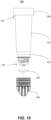
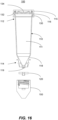
- the base 150 and filter assembly are removed from the apparatus 100, as illustrated in FIGS. 15-16 .
- the airtight seal e.g., provided by the attachment of the lid 130 with the body 110, and by the sizing of the distal outlet 119, retain a substantial portion of the liquid within the loading compartment 111 of the body for subsequent reuse.
- the sample, as well as the filter assembly 120, is then placed in mold and infiltrated with paraffin wax for subsequent sectioning on a microtome, for example.
- a microtome for example.
- the entire filter assembly 120 including filter membrane 124 and the body portion 131 and 138, is sliceable by a microtome to form slices of cell block (and filter assembly) for mounting on a glass slide for analysis on a microscope or for other analyses such as microcellular analysis, e.g., DNA, RNA, and/or protein.
- the materials of the body portion 131 and membrane 124 are particularly selected for their chemical compatibility and sectionability.
- chemical compatibility no significant quantity of material dissolves when exposed to typical tissue processing reagents and temperatures.
- the materials are exposed to ethanol, xylene and formalin, up to about 60°C.
- sectionability the materials, e.g., LLDPE and ePTFE, are sliceable together with the contained cell block such that sufficiently thin slices can be achieved with a microtome for use in microscopy and other laboratory techniques.
- the sectionability characteristics of the materials provide for insignificant wear on the microtome blade, and that subsequent slices are uniform, and mechanically stable, e.g., they do not break apart during slicing and subsequent handling.
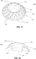
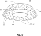
- Cell block filter assembly 220 can be used in connection with cell block system 100 in the same manner as cell block filter assembly 120.
- the filter assembly 220 comprises a body portion 231 defining a well 222.
- the body portion 231 is typically a non-porous member, and is fabricated of the same materials as body portion 131, e.g., LLDPE, LDPE, PVA, or a combination thereof.
- a filter membrane 224 is disposed within the well 222 of the body portion 231, and is fabricated of the same materials as membrane 124, e.g., ePTFE.
- the body portion 231 includes a hub portion 232 that defines the well 222.
- a top wall portion 234 extends peripherally from the hub portion 232 and defines a plurality of holes 238.
- a conical or tapered wall portion 235 extends from the top wall portion 234 and also defines a plurality of holes 236.
- the plurality of partially cut-outs or serrations 237 are formed about the periphery of tapered wall portion 235.
- the openings 236, 237 and 238 allow the filter assembly 220 (and thus the tissue sample formed within) to be secured in the wax or other medium during the slicing process.
- Cell block system 300 includes an elongate tubular body 310, a cell block filter assembly 320, and a base member 350.
- the elongate tubular body 310 defines an interior loading chamber 311, and has a proximal end 312 and a distal end 314.
- the elongate tubular body has a first diameter d3 at the proximal end 312 and a second diameter d4 at the distal end 314, wherein the second diameter d4 is smaller than the first diameter d3, as will be discussed in greater detail herein.
- a section 318 disposed between the proximal end 312 and the distal end 314 of the elongate tubular body 310, has a decreasing diameter along a length thereof to define a generally conical configuration, and further includes structure for receiving the cell block filter assembly as will be described below.
- the tubular body narrows in an offset fashion, such that the distal outlet 319 is offset from the longitudinal axis L of the elongated body 310.
- the elongate tubular body 310 defines an opening 313 at the proximal end 312 of the body (top of the figure).
- the opening 313 is closed by a cover 360, which provides a substantially airtight seal with the rim 315.
- the lid 360 can be configured with external screw thread or threads 317 to engage a thread or threads 316 disposed on the inside surface of a proximal section 312 of the elongate tubular body 310.
- suitable methods and features can be used to engage the cover and elongate tubular body, such as a snap fit, ratchet fit, interference fit, vacuum seal or other methods of engagement, as would be appreciated by one of ordinary skill in the art.
- the elongate tubular body is preloaded with a fixative in the loading chamber.
- a "fixative” as used herein refers to a compound, such as formalin, ethanol, methanol, RPMI, saline for preservation and/or transportation of the sample.
- the filter assembly 320 defines a border 321 circumscribing an open off-center well 322 in which a filter membrane 324 is disposed.
- the well 322 is configured with an opening sized to cooperate with the distal outlet 319 on the distal section 318 of the elongate tubular body 310. (See FIG. 23 ).
- cells may be collected in the center well 322, such as after filtration, to provide a substantially cylindrical cell block.
- the base member 350 is configured to support the cell block filter assembly 320, and to be attached to the distal section 318 of tubular body 310 to secure the assembly 320 thereto.
- the outer surface of the distal section 318 can be configured with a thread or a plurality of threads 348 to engage with a thread or threads 349 on interior portion of the base member 350 to secure the base member 350 to the distal section 318 of the elongate tubular body 310, thereby stabilizing the cell block filter assembly 320 therein during centrifuging or other similar processes.
- the filter assembly 320 is ready to receive a biological sample through distal opening of elongate body 310.
- cap 360 can be secured to the tubular body 310.
- the sample can be delivered via a needle such as a hypodermic needle or an aspiration needle through a cap 360 configured with a puncturable, resealable center portion that is already engaged with the tubular body 310.
- the biological sample is securely sealed within the cell block system 300 for storage and/or transport from the locus where it is taken, such as an examination room or an operating room, to the locus where it can be analyzed, such as a pathology lab.
- the sealed cell block apparatus can be subjected to centrifuging process(es) without any of the sample escaping the sample loading chamber and passing through the cell block filter assembly 320. Accordingly, the biological sample is separated or stratified (i.e. fluid content disposed above solid content) during the centrifuging process.
- the filter assembly 320 includes a body portion 321 typically fabricated from a non-porous material and defines a well 322 that is off-center.
- a filter membrane 324 is disposed within the well 322.
- support member(s) 325 extend from a border 321 to support the well 322.
- the filter assembly 320 further includes a flexible hinge 328 (also referred to as a "living hinge") and a cover portion 330.
- the hinge portion 328 can be fabricated from the same material as the body of the filter assembly, linear low-density polyethylene (LLDPE) material.
- LLDPE linear low-density polyethylene
- the cover includes an aperture that is covered with the filter membrane material.
- the filter membrane 324 is fabricated from a porous membrane, such as ePTFE or track etched polyethylene terephthalate (PET), for example.
- the membrane is specified so as to be small enough to prevent sample loss, but large enough for sufficient reagent infiltration into the sample.
- the membrane 324 is attached by heat sealing, such as thermal bonding, to the lid 330 and the well 322 and covers an opening at the bottom portion of the well 322.
- the membrane is secured by ultrasonic welding, or by an adhesive.
Landscapes
- Health & Medical Sciences (AREA)
- Chemical & Material Sciences (AREA)
- Life Sciences & Earth Sciences (AREA)
- General Health & Medical Sciences (AREA)
- Analytical Chemistry (AREA)
- Immunology (AREA)
- Biochemistry (AREA)
- General Physics & Mathematics (AREA)
- Physics & Mathematics (AREA)
- Pathology (AREA)
- Engineering & Computer Science (AREA)
- Biomedical Technology (AREA)
- Molecular Biology (AREA)
- Hematology (AREA)
- Clinical Laboratory Science (AREA)
- Chemical Kinetics & Catalysis (AREA)
- Sampling And Sample Adjustment (AREA)
Claims (13)
- Appareil médical comprenant :un corps allongé (310) présentant une extrémité proximale (312), une extrémité distale (314), et définissant une chambre de chargement (311) entre l'extrémité proximale et l'extrémité distale pour y stocker un liquide, le corps allongé définissant une sortie (319) au niveau de l'extrémité distale de celui-ci ;un ensemble de filtre de bloc cellulaire (320) comprenant :un corps de bloc cellulaire (321) définissant une partie de puits (322) pouvant venir en prise de manière complémentaire avec l'extrémité distale du corps allongé pour recevoir du fluide provenant de la sortie du corps allongé et définissant une ouverture de puits sur un fond de celui-ci ;une membrane de filtre (324) disposée à travers l'ouverture du puits à l'intérieur de la partie de puits ; etun élément de couvercle (330) pouvant être positionné sur la partie de puits ; etun élément de base (350) pour fixer l'ensemble de filtre de bloc cellulaire (320) au niveau de l'extrémité distale (314) du corps allongé (310), et dans lequel la surface extérieure de l'extrémité distale du corps allongé est conçue pour venir en prise avec l'élément de base ;dans lequel l'ensemble de filtre de bloc cellulaire peut être découpé en tranches présentant une épaisseur adaptée au montage sur une lame de laboratoire ; etdans lequel l'élément de base (350) empêche le passage du fluide hors de l'ensemble de filtre (320).
- Appareil médical selon la revendication 1, dans lequel l'élément de base (350) est fixé au corps allongé (310) avec une prise filetée, un ajustement par friction ou une prise à cliquet.
- Appareil médical selon la revendication 1, dans lequel le corps de bloc cellulaire (321) est fabriqué essentiellement à partir de LLDPE.
- Appareil médical selon la revendication 1, dans lequel l'élément de couvercle (330) est fabriqué essentiellement à partir de LLDPE.
- Appareil médical selon la revendication 1, dans lequel l'élément de couvercle (330) définit une ouverture de couvercle, l'élément de couvercle comprenant en outre une membrane de filtre disposée à travers l'ouverture de couvercle.
- Appareil médical selon la revendication 5, dans lequel l'élément de couvercle (330) comprend une partie de charnière (328) pour relier l'élément de couvercle au corps de bloc cellulaire.
- Appareil médical selon la revendication 6, dans lequel la partie de charnière (328) est une charnière mobile.
- Appareil médical selon la revendication 1, dans lequel la membrane de filtre (324) est fabriquée essentiellement à partir d'ePTFE ou de PET.
- Appareil médical selon la revendication 1, dans lequel l'extrémité distale (314) du corps allongé (310) définit un diamètre plus petit que l'extrémité proximale (312) pour définir une partie généralement conique.
- Appareil médical selon la revendication 1, dans lequel la sortie (319) est décalée par rapport à l'axe longitudinal du corps allongé (310).
- Appareil médical selon la revendication 1, comprenant également un capuchon (360) disposé sur l'extrémité proximale (312) du corps allongé (310), le capuchon étant conçu pour venir en prise avec l'extrémité proximale du corps allongé pour former une fermeture hermétique entre le capuchon et le corps allongé.
- Appareil médical selon la revendication 11, dans lequel le capuchon (360) est en prise fileté avec le corps allongé (310) avec des filetages formés sur la surface extérieure du capuchon et des filetages formés sur la surface intérieure de l'extrémité proximale (312) du corps allongé.
- Appareil médical selon la revendication 11, dans lequel le capuchon (330) est pourvu d'une partie pouvant être perforée et refermée.
Applications Claiming Priority (3)
| Application Number | Priority Date | Filing Date | Title |
|---|---|---|---|
| US201962804875P | 2019-02-13 | 2019-02-13 | |
| US202062966264P | 2020-01-27 | 2020-01-27 | |
| PCT/US2020/018121 WO2020168085A2 (fr) | 2019-02-13 | 2020-02-13 | Appareil médical et procédé de prélèvement et de préparation d'échantillons biologiques |
Publications (3)
| Publication Number | Publication Date |
|---|---|
| EP3924712A2 EP3924712A2 (fr) | 2021-12-22 |
| EP3924712A4 EP3924712A4 (fr) | 2022-11-23 |
| EP3924712B1 true EP3924712B1 (fr) | 2024-10-16 |
Family
ID=72044017
Family Applications (1)
| Application Number | Title | Priority Date | Filing Date |
|---|---|---|---|
| EP20755649.9A Active EP3924712B1 (fr) | 2019-02-13 | 2020-02-13 | Appareil médical de prélèvement et de préparation d'échantillons biologiques |
Country Status (3)
| Country | Link |
|---|---|
| US (1) | US20210372894A1 (fr) |
| EP (1) | EP3924712B1 (fr) |
| WO (1) | WO2020168085A2 (fr) |
Families Citing this family (5)
| Publication number | Priority date | Publication date | Assignee | Title |
|---|---|---|---|---|
| CN113390692B (zh) * | 2021-05-24 | 2023-02-28 | 杭州电子科技大学 | 一种用于自动制备细胞蜡块的离心试管 |
| WO2023192899A2 (fr) * | 2022-03-29 | 2023-10-05 | The Trustees Of Columbia University In The City Of New York | Plate-forme multi-tissu utilisant des micropuits |
| EP4712770A1 (fr) * | 2023-05-19 | 2026-03-25 | The Trustees Of Columbia University In The City Of New York | Dispositif de perfusion rotatif pour la culture de cellules biologiques |
| CN116990082B (zh) * | 2023-06-28 | 2024-03-19 | 辽宁千一测试评价科技发展有限公司 | 一种基于生物体液检测用的取样装置及其取样方法 |
| ES3042308B2 (es) * | 2024-05-17 | 2026-04-13 | Administracion General De La Comunidad Autonoma De Euskadi | Dispositivo de extracción de tejido y empuñadura para dispositivo de extracción de tejido |
Family Cites Families (13)
| Publication number | Priority date | Publication date | Assignee | Title |
|---|---|---|---|---|
| BR0007064A (pt) * | 1999-09-03 | 2001-07-31 | Baxter Int | Câmara de separação de sangue com passagens de escoamento de sangue preformadas e conexão centralizada em tubulação externa |
| US7488297B2 (en) * | 2003-07-30 | 2009-02-10 | Patrice Flaherty | Blood collecting devices |
| GB201004072D0 (en) * | 2010-03-11 | 2010-04-28 | Turzi Antoine | Process, tube and device for the preparation of wound healant composition |
| CN201825948U (zh) * | 2010-09-30 | 2011-05-11 | 何洪敏 | 脱落细胞制备细胞块蜡块用组合式离心管 |
| US8858518B2 (en) * | 2011-02-22 | 2014-10-14 | Mark E. Schafer | Canister for autologous fat transfer |
| JP6076360B2 (ja) * | 2011-10-18 | 2017-02-08 | ザ・トラスティーズ・オブ・コロンビア・ユニバーシティ・イン・ザ・シティ・オブ・ニューヨーク | 生体試料を収集するための医療装置および方法 |
| JPWO2013073558A1 (ja) * | 2011-11-14 | 2015-04-02 | ロート製薬株式会社 | 液体試料検査方法並びに検体抽出ノズル、検体抽出容器及び液体試料検査キット |
| AU2013347980B2 (en) * | 2012-11-20 | 2017-09-28 | The Trustees Of Columbia University In The City Of New York | Medical apparatus and method for collecting biological samples |
| CN203079956U (zh) * | 2013-03-22 | 2013-07-24 | 黑龙江省林业科学研究所 | 一种适用于实验室组织培养容器的一次性无菌透气封口膜 |
| CN106662519B (zh) * | 2014-08-20 | 2021-10-15 | 研究三角协会 | 用于检测颗粒的装置、系统和方法 |
| US10088398B2 (en) * | 2015-02-11 | 2018-10-02 | Emd Millipore Corporation | Stirred cell and method of using same |
| US20170036203A1 (en) * | 2015-08-07 | 2017-02-09 | Nalge Nunc International Corporation | Slow draw transfer pipettes and related methods |
| CN109207340B (zh) | 2017-06-30 | 2022-08-12 | 开启基因股份有限公司 | 核酸萃取组件 |
-
2020
- 2020-02-13 EP EP20755649.9A patent/EP3924712B1/fr active Active
- 2020-02-13 WO PCT/US2020/018121 patent/WO2020168085A2/fr not_active Ceased
-
2021
- 2021-08-13 US US17/402,249 patent/US20210372894A1/en active Pending
Also Published As
| Publication number | Publication date |
|---|---|
| EP3924712A2 (fr) | 2021-12-22 |
| EP3924712A4 (fr) | 2022-11-23 |
| US20210372894A1 (en) | 2021-12-02 |
| WO2020168085A2 (fr) | 2020-08-20 |
| WO2020168085A3 (fr) | 2020-09-24 |
Similar Documents
| Publication | Publication Date | Title |
|---|---|---|
| EP3924712B1 (fr) | Appareil médical de prélèvement et de préparation d'échantillons biologiques | |
| US20260090793A1 (en) | Medical Apparatus And Method For Collecting Biological Samples | |
| EP2768594B1 (fr) | Appareil médical et procédé de prélèvement d'échantillons biologiques | |
| EP0654972B8 (fr) | Procede et appareil permettant d'obtenir des monocouches cytologiques | |
| AU645689B2 (en) | Liquid specimen container and attachable testing modules | |
| EP4065001B1 (fr) | Ensemble porte-tissu biologique et composants associés | |
| WO2004043601A1 (fr) | Tube a essai avec accessoire interieur | |
| US7687032B2 (en) | Filter assembly for molecular testing | |
| US6106483A (en) | Apparatus for obtaining a cytology monolayer | |
| US20040025935A1 (en) | Test tube insert | |
| WO2004014556A9 (fr) | Appareil et procede pour collecter les sediments d'un echantillon de fluide |
Legal Events
| Date | Code | Title | Description |
|---|---|---|---|
| STAA | Information on the status of an ep patent application or granted ep patent |
Free format text: STATUS: THE INTERNATIONAL PUBLICATION HAS BEEN MADE |
|
| PUAI | Public reference made under article 153(3) epc to a published international application that has entered the european phase |
Free format text: ORIGINAL CODE: 0009012 |
|
| STAA | Information on the status of an ep patent application or granted ep patent |
Free format text: STATUS: REQUEST FOR EXAMINATION WAS MADE |
|
| 17P | Request for examination filed |
Effective date: 20210913 |
|
| AK | Designated contracting states |
Kind code of ref document: A2 Designated state(s): AL AT BE BG CH CY CZ DE DK EE ES FI FR GB GR HR HU IE IS IT LI LT LU LV MC MK MT NL NO PL PT RO RS SE SI SK SM TR |
|
| DAV | Request for validation of the european patent (deleted) | ||
| DAX | Request for extension of the european patent (deleted) | ||
| A4 | Supplementary search report drawn up and despatched |
Effective date: 20221021 |
|
| RIC1 | Information provided on ipc code assigned before grant |
Ipc: C12M 1/24 20060101ALI20221017BHEP Ipc: G01N 1/40 20060101ALI20221017BHEP Ipc: G01N 1/31 20060101AFI20221017BHEP |
|
| P01 | Opt-out of the competence of the unified patent court (upc) registered |
Effective date: 20230314 |
|
| STAA | Information on the status of an ep patent application or granted ep patent |
Free format text: STATUS: EXAMINATION IS IN PROGRESS |
|
| 17Q | First examination report despatched |
Effective date: 20230719 |
|
| GRAP | Despatch of communication of intention to grant a patent |
Free format text: ORIGINAL CODE: EPIDOSNIGR1 |
|
| STAA | Information on the status of an ep patent application or granted ep patent |
Free format text: STATUS: GRANT OF PATENT IS INTENDED |
|
| INTG | Intention to grant announced |
Effective date: 20240517 |
|
| GRAS | Grant fee paid |
Free format text: ORIGINAL CODE: EPIDOSNIGR3 |
|
| GRAA | (expected) grant |
Free format text: ORIGINAL CODE: 0009210 |
|
| STAA | Information on the status of an ep patent application or granted ep patent |
Free format text: STATUS: THE PATENT HAS BEEN GRANTED |
|
| AK | Designated contracting states |
Kind code of ref document: B1 Designated state(s): AL AT BE BG CH CY CZ DE DK EE ES FI FR GB GR HR HU IE IS IT LI LT LU LV MC MK MT NL NO PL PT RO RS SE SI SK SM TR |
|
| REG | Reference to a national code |
Ref country code: GB Ref legal event code: FG4D |
|
| REG | Reference to a national code |
Ref country code: CH Ref legal event code: EP |
|
| REG | Reference to a national code |
Ref country code: IE Ref legal event code: FG4D |
|
| REG | Reference to a national code |
Ref country code: DE Ref legal event code: R096 Ref document number: 602020039580 Country of ref document: DE |
|
| REG | Reference to a national code |
Ref country code: LT Ref legal event code: MG9D |
|
| REG | Reference to a national code |
Ref country code: NL Ref legal event code: MP Effective date: 20241016 |
|
| REG | Reference to a national code |
Ref country code: AT Ref legal event code: MK05 Ref document number: 1733274 Country of ref document: AT Kind code of ref document: T Effective date: 20241016 |
|
| PG25 | Lapsed in a contracting state [announced via postgrant information from national office to epo] |
Ref country code: NL Free format text: LAPSE BECAUSE OF FAILURE TO SUBMIT A TRANSLATION OF THE DESCRIPTION OR TO PAY THE FEE WITHIN THE PRESCRIBED TIME-LIMIT Effective date: 20241016 |
|
| PG25 | Lapsed in a contracting state [announced via postgrant information from national office to epo] |
Ref country code: NL Free format text: LAPSE BECAUSE OF FAILURE TO SUBMIT A TRANSLATION OF THE DESCRIPTION OR TO PAY THE FEE WITHIN THE PRESCRIBED TIME-LIMIT Effective date: 20241016 |
|
| PG25 | Lapsed in a contracting state [announced via postgrant information from national office to epo] |
Ref country code: PT Free format text: LAPSE BECAUSE OF FAILURE TO SUBMIT A TRANSLATION OF THE DESCRIPTION OR TO PAY THE FEE WITHIN THE PRESCRIBED TIME-LIMIT Effective date: 20250217 Ref country code: HR Free format text: LAPSE BECAUSE OF FAILURE TO SUBMIT A TRANSLATION OF THE DESCRIPTION OR TO PAY THE FEE WITHIN THE PRESCRIBED TIME-LIMIT Effective date: 20241016 Ref country code: IS Free format text: LAPSE BECAUSE OF FAILURE TO SUBMIT A TRANSLATION OF THE DESCRIPTION OR TO PAY THE FEE WITHIN THE PRESCRIBED TIME-LIMIT Effective date: 20250216 |
|
| PGFP | Annual fee paid to national office [announced via postgrant information from national office to epo] |
Ref country code: DE Payment date: 20250227 Year of fee payment: 6 |
|
| PG25 | Lapsed in a contracting state [announced via postgrant information from national office to epo] |
Ref country code: FI Free format text: LAPSE BECAUSE OF FAILURE TO SUBMIT A TRANSLATION OF THE DESCRIPTION OR TO PAY THE FEE WITHIN THE PRESCRIBED TIME-LIMIT Effective date: 20241016 |
|
| PG25 | Lapsed in a contracting state [announced via postgrant information from national office to epo] |
Ref country code: BG Free format text: LAPSE BECAUSE OF FAILURE TO SUBMIT A TRANSLATION OF THE DESCRIPTION OR TO PAY THE FEE WITHIN THE PRESCRIBED TIME-LIMIT Effective date: 20241016 |
|
| PG25 | Lapsed in a contracting state [announced via postgrant information from national office to epo] |
Ref country code: ES Free format text: LAPSE BECAUSE OF FAILURE TO SUBMIT A TRANSLATION OF THE DESCRIPTION OR TO PAY THE FEE WITHIN THE PRESCRIBED TIME-LIMIT Effective date: 20241016 |
|
| PG25 | Lapsed in a contracting state [announced via postgrant information from national office to epo] |
Ref country code: NO Free format text: LAPSE BECAUSE OF FAILURE TO SUBMIT A TRANSLATION OF THE DESCRIPTION OR TO PAY THE FEE WITHIN THE PRESCRIBED TIME-LIMIT Effective date: 20250116 |
|
| PG25 | Lapsed in a contracting state [announced via postgrant information from national office to epo] |
Ref country code: LV Free format text: LAPSE BECAUSE OF FAILURE TO SUBMIT A TRANSLATION OF THE DESCRIPTION OR TO PAY THE FEE WITHIN THE PRESCRIBED TIME-LIMIT Effective date: 20241016 Ref country code: AT Free format text: LAPSE BECAUSE OF FAILURE TO SUBMIT A TRANSLATION OF THE DESCRIPTION OR TO PAY THE FEE WITHIN THE PRESCRIBED TIME-LIMIT Effective date: 20241016 Ref country code: GR Free format text: LAPSE BECAUSE OF FAILURE TO SUBMIT A TRANSLATION OF THE DESCRIPTION OR TO PAY THE FEE WITHIN THE PRESCRIBED TIME-LIMIT Effective date: 20250117 |
|
| PGFP | Annual fee paid to national office [announced via postgrant information from national office to epo] |
Ref country code: CH Payment date: 20250304 Year of fee payment: 6 |
|
| PG25 | Lapsed in a contracting state [announced via postgrant information from national office to epo] |
Ref country code: PL Free format text: LAPSE BECAUSE OF FAILURE TO SUBMIT A TRANSLATION OF THE DESCRIPTION OR TO PAY THE FEE WITHIN THE PRESCRIBED TIME-LIMIT Effective date: 20241016 |
|
| PGFP | Annual fee paid to national office [announced via postgrant information from national office to epo] |
Ref country code: FR Payment date: 20250225 Year of fee payment: 6 |
|
| PGFP | Annual fee paid to national office [announced via postgrant information from national office to epo] |
Ref country code: GB Payment date: 20250227 Year of fee payment: 6 |
|
| PG25 | Lapsed in a contracting state [announced via postgrant information from national office to epo] |
Ref country code: RS Free format text: LAPSE BECAUSE OF FAILURE TO SUBMIT A TRANSLATION OF THE DESCRIPTION OR TO PAY THE FEE WITHIN THE PRESCRIBED TIME-LIMIT Effective date: 20250116 |
|
| PG25 | Lapsed in a contracting state [announced via postgrant information from national office to epo] |
Ref country code: SM Free format text: LAPSE BECAUSE OF FAILURE TO SUBMIT A TRANSLATION OF THE DESCRIPTION OR TO PAY THE FEE WITHIN THE PRESCRIBED TIME-LIMIT Effective date: 20241016 |
|
| PG25 | Lapsed in a contracting state [announced via postgrant information from national office to epo] |
Ref country code: DK Free format text: LAPSE BECAUSE OF FAILURE TO SUBMIT A TRANSLATION OF THE DESCRIPTION OR TO PAY THE FEE WITHIN THE PRESCRIBED TIME-LIMIT Effective date: 20241016 |
|
| REG | Reference to a national code |
Ref country code: DE Ref legal event code: R097 Ref document number: 602020039580 Country of ref document: DE |
|
| PG25 | Lapsed in a contracting state [announced via postgrant information from national office to epo] |
Ref country code: EE Free format text: LAPSE BECAUSE OF FAILURE TO SUBMIT A TRANSLATION OF THE DESCRIPTION OR TO PAY THE FEE WITHIN THE PRESCRIBED TIME-LIMIT Effective date: 20241016 |
|
| PG25 | Lapsed in a contracting state [announced via postgrant information from national office to epo] |
Ref country code: RO Free format text: LAPSE BECAUSE OF FAILURE TO SUBMIT A TRANSLATION OF THE DESCRIPTION OR TO PAY THE FEE WITHIN THE PRESCRIBED TIME-LIMIT Effective date: 20241016 |
|
| PG25 | Lapsed in a contracting state [announced via postgrant information from national office to epo] |
Ref country code: SK Free format text: LAPSE BECAUSE OF FAILURE TO SUBMIT A TRANSLATION OF THE DESCRIPTION OR TO PAY THE FEE WITHIN THE PRESCRIBED TIME-LIMIT Effective date: 20241016 |
|
| PG25 | Lapsed in a contracting state [announced via postgrant information from national office to epo] |
Ref country code: CZ Free format text: LAPSE BECAUSE OF FAILURE TO SUBMIT A TRANSLATION OF THE DESCRIPTION OR TO PAY THE FEE WITHIN THE PRESCRIBED TIME-LIMIT Effective date: 20241016 |
|
| PG25 | Lapsed in a contracting state [announced via postgrant information from national office to epo] |
Ref country code: IT Free format text: LAPSE BECAUSE OF FAILURE TO SUBMIT A TRANSLATION OF THE DESCRIPTION OR TO PAY THE FEE WITHIN THE PRESCRIBED TIME-LIMIT Effective date: 20241016 |
|
| PLBE | No opposition filed within time limit |
Free format text: ORIGINAL CODE: 0009261 |
|
| STAA | Information on the status of an ep patent application or granted ep patent |
Free format text: STATUS: NO OPPOSITION FILED WITHIN TIME LIMIT |
|
| PG25 | Lapsed in a contracting state [announced via postgrant information from national office to epo] |
Ref country code: SE Free format text: LAPSE BECAUSE OF FAILURE TO SUBMIT A TRANSLATION OF THE DESCRIPTION OR TO PAY THE FEE WITHIN THE PRESCRIBED TIME-LIMIT Effective date: 20241016 |
|
| PG25 | Lapsed in a contracting state [announced via postgrant information from national office to epo] |
Ref country code: MC Free format text: LAPSE BECAUSE OF FAILURE TO SUBMIT A TRANSLATION OF THE DESCRIPTION OR TO PAY THE FEE WITHIN THE PRESCRIBED TIME-LIMIT Effective date: 20241016 |
|
| 26N | No opposition filed |
Effective date: 20250717 |
|
| PG25 | Lapsed in a contracting state [announced via postgrant information from national office to epo] |
Ref country code: LU Free format text: LAPSE BECAUSE OF NON-PAYMENT OF DUE FEES Effective date: 20250213 |
|
| REG | Reference to a national code |
Ref country code: BE Ref legal event code: MM Effective date: 20250228 |
|
| PG25 | Lapsed in a contracting state [announced via postgrant information from national office to epo] |
Ref country code: BE Free format text: LAPSE BECAUSE OF NON-PAYMENT OF DUE FEES Effective date: 20250228 |
|
| PG25 | Lapsed in a contracting state [announced via postgrant information from national office to epo] |
Ref country code: IE Free format text: LAPSE BECAUSE OF NON-PAYMENT OF DUE FEES Effective date: 20250213 |